-
null
Configuring Layer 3 Interfaces
This chapter describes the Layer 3 interfaces on a Catalyst 4500 series switch. It also provides guidelines, procedures, and configuration examples.
This chapter includes the following major sections:
- About Layer 3 Interfaces
- Configuration Guidelines
- Configuring Logical Layer 3 VLAN Interfaces
- Configuring Logical Layer 3 GRE Tunnel Interfaces
- Configuring VLANs as Layer 3 Interfaces
- Configuring Physical Layer 3 Interfaces
- Configuring Multipoint GRE

Note![]() For complete syntax and usage information for the switch commands used in this chapter, see the
For complete syntax and usage information for the switch commands used in this chapter, see the
Cisco IOS Command Reference Guides for the Catalyst 4500 Series Switch.
If a command is not in the Cisco Catalyst 4500 Series Switch Command Reference , you can locate it in the Cisco IOS Master Command List, All Releases.
About Layer 3 Interfaces
The Catalyst 4500 series switch supports Layer 3 interfaces with the Cisco IOS IP and IP routing protocols. Layer 3, the network layer, is primarily responsible for the routing of data in packets across logical internetwork paths.
Layer 2, the data link layer, contains the protocols that control the physical layer (Layer 1) and how data is framed before being transmitted on the medium. The Layer 2 function of filtering and forwarding data in frames between two segments on a LAN is known as bridging.
The Catalyst 4500 series switch supports two types of Layer 3 interfaces. The logical Layer 3 VLAN interfaces integrate the functions of routing and bridging. The physical Layer 3 interfaces allow the Catalyst 4500 series switch to be configured like a traditional router.
Note![]() On a Catalyst 4500 series switch, a physical Layer 3 interface has MAC address learning enabled.
On a Catalyst 4500 series switch, a physical Layer 3 interface has MAC address learning enabled.
This section contains the following subsections:
- Logical Layer 3 VLAN Interfaces
- Physical Layer 3 Interfaces
- Understanding SVI Autostate Exclude
- Understanding Layer 3 Interface Counters
Logical Layer 3 VLAN Interfaces
The logical Layer 3 VLAN interfaces provide logical routing interfaces to VLANs on Layer 2 switches. A traditional network requires a physical interface from a router to a switch to perform inter-VLAN routing. The Catalyst 4500 series switch supports inter-VLAN routing by integrating the routing and bridging functions on a single Catalyst 4500 series switch.
Figure 36-1 shows how the routing and bridging functions in the three physical devices of the traditional network are performed logically on one Catalyst 4500 series switch.
Figure 36-1 Logical Layer 3 VLAN Interfaces for the Catalyst 4500 Series Switch

Physical Layer 3 Interfaces
The physical Layer 3 interfaces support capabilities equivalent to a traditional router. These Layer 3 interfaces provide hosts with physical routing interfaces to a Catalyst 4500 series switch.
Figure 36-2 shows how the Catalyst 4500 series switch functions as a traditional router.
Figure 36-2 Physical Layer 3 Interfaces for the Catalyst 4500 Series Switch

Understanding SVI Autostate Exclude
To be up/up, a router VLAN interface must fulfill the following general conditions:
- The VLAN exists and is active on the VLAN database of the switch.
- The VLAN interface exists on the router and is not administratively down.
- At least one Layer 2 (access port or trunk) port exists, has a link up on this VLAN, and is in spanning-tree forwarding state on the VLAN.
Note![]() The protocol line state for the VLAN interfaces comes up when the first switch port belonging to the corresponding VLAN link comes up and is in spanning-tree forwarding state.
The protocol line state for the VLAN interfaces comes up when the first switch port belonging to the corresponding VLAN link comes up and is in spanning-tree forwarding state.
Ordinarily, when a VLAN interface has multiple ports in the VLAN, the SVI goes down when all the ports in the VLAN go down. The SVI Autostate Exclude feature provides a knob to mark a port so that it is not counted in the SVI up and down calculation and applies to all VLANs that are enabled on that port.
A VLAN interface is brought up after the Layer 2 port has had time to converge (that is, transition from listening-learning to forwarding). This prevents routing protocols and other features from using the VLAN interface as if it were fully operational. It also prevents other problems from occurring, such as routing black holes.
Understanding Layer 3 Interface Counters
Note![]() Supervisor Engine 9-E, 8L-E, 8-E, 7-LE, 7-E, 6L-E, do not support Layer 2 interface counters. However, they do support Layer 3 (SVI) interface counters.
Supervisor Engine 9-E, 8L-E, 8-E, 7-LE, 7-E, 6L-E, do not support Layer 2 interface counters. However, they do support Layer 3 (SVI) interface counters.
When you run IPv4 and IPv6 on Supervisor Engines 9-E, 8L-E, 8-E, 7-LE, 7-E, 6L-E, 6-E, packets are routed in hardware by the forwarding engine. They support the following statistics for counting routed packets with a maximum of 4092 interfaces:
For each counter type, both the number of packets and the total number of bytes received or transmitted are counted. You can collect these statistics uniquely for IPv4 and IPv6 traffic.
Because the total number of supported Layer 3 interfaces exceeds the number of counters supported by hardware, all Layer 3 interfaces might not have counters. You assign counters to Layer 3 interfaces; the default configuration for a Layer 3 interface has no counters.
You can configure collection statistics at an interface level in one of the four ways (see Table 36-1 ). The maximum number of interfaces applied to the configuration depends on the collection mode.
When mixing these configured modes, the rule is as follows:
(number of v4/v6/v4v6combined interfaces) + 2*(number of v4v6separate interfaces) <= 4092
Note![]() To enable Layer 3 interface counters, you need to enter the counter command in interface mode. For instructions, see the “Configuring Layer 3 Interface Counters” section.
To enable Layer 3 interface counters, you need to enter the counter command in interface mode. For instructions, see the “Configuring Layer 3 Interface Counters” section.
The hardware counters are displayed in the output of the show interface command, as shown in the following example. Counter fields that are updated when the counter configuration is present are highlighted.
The output of the previous configuration depends on the counter configuration ( Table 36-2 ).
|
|
|
|---|---|
Configuration Guidelines
The Catalyst 4500 series switch supports AppleTalk routing and IPX routing. For AppleTalk routing and IPX routing information, refer to “Configuring AppleTalk” and “Configuring Novell IPX” in the Cisco IOS AppleTalk and Novell IPX configuration guides at the following URLs:
http://www.cisco.com/en/US/docs/ios/at/configuration/guide/12_4/atk_12_4_book.html
http://www.cisco.com/en/US/docs/ios/novipx/configuration/guide/config_novellipx_ps6350_TSD_Products_Configuration_Guide_Chapter.html
Note![]() Supervisor Engine 9-E, 8L-E, 8-E, 7-LE, 7-E, 6L-E, and 6-E do not support AppleTalk and IPX routing.
Supervisor Engine 9-E, 8L-E, 8-E, 7-LE, 7-E, 6L-E, and 6-E do not support AppleTalk and IPX routing.
- Catalyst 4500 series switches do not support subinterfaces or the encapsulation keyword on
Layer 3 Fast Ethernet, Gigabit Ethernet, 10-Gigabit Ethernet interfaces. - Starting IOS XE 3.11.0, Catalyst 4500 series switches do not support egress Access Controlled Lists (ACLs) on a tunnel interface and on the source interface of the tunnel.
Note![]() As with any Layer 3 interface running Cisco IOS software, the IP address and network assigned to an SVI cannot overlap those assigned to any other Layer 3 interface on the switch.
As with any Layer 3 interface running Cisco IOS software, the IP address and network assigned to an SVI cannot overlap those assigned to any other Layer 3 interface on the switch.
Configuring Logical Layer 3 GRE Tunnel Interfaces
Tunnels are point-to-point dedicated virtual links to transport packets from one endpoint to another. Generic Routing Encapsulation (GRE) is a tunneling protocol used to encapsulate network layer protocols inside virtual point-to-point links. A GRE tunnel only provides encapsulation and not encryption.
With GRE, devices running a given network layer protocol can communicate over a network running a different network layer protocol. A network receives and encapsulates the native packet into another network protocol and sends the encapsulated packet towards its de-encapsulation point. The encapsulation point is the tunnel entry and the de-encapsulation point is the tunnel exit.
Note![]() Beginning in Cisco IOS XE Release 3.7.1E, GRE tunnels are supported on the hardware on Cisco Catalyst 4500 Series switches.
Beginning in Cisco IOS XE Release 3.7.1E, GRE tunnels are supported on the hardware on Cisco Catalyst 4500 Series switches.
When GRE is configured with tunnel options (such as key, checksum, etc.), packets are switched in software. When GRE is configured without tunnel options, packets are hardware-switched.
Restrictions and Limitations for Logical Layer 3 GRE Tunnel Interfaces:
- Multicast routing is not supported on GRE tunnels, so PIM configuration is not supported on a GRE tunnel interface.
- Limitation relating to GRE-encapsulated packets that are switched in hardware (applies only to Catalyst 4500-X Series Switches):
If a GRE tunnel is configured on a Catalyst 4500 switch and the ingress to this device is through a Layer 2 interface which has an SVI configured locally and is running HSRP (and is the current active), GRE encapsulated unicast traffic is not sent across the endpoints of the GRE tunnel, because of which routing adjacencies cannot be established and pings across the GRE tunnel do not work.
To work around this problem, configure the HSRP group to the use the burned-in address (BIA) feature ( standby use-bia interface configuration command). It enables HSRP groups to use an interface's burned-in MAC address (or physical MAC address) instead of a virtual MAC address. Note that configuring the standby use-bia interface configuration command may slow down convergence after an HSRP switchover, since the new active has to send a gratuitous ARP to refresh the ARP entries through the subnet. For more information, see: https://www.cisco.com/c/en/us/support/docs/ip/hot-standby-router-protocol-hsrp/9281-3.html.
To configure a GRE tunnel, perform this task:
This example shows how to configure the logical Layer 3 GRE tunnel interface tunnel 2:
Configuring Logical Layer 3 VLAN Interfaces
Note![]() Before you can configure logical Layer 3 VLAN interfaces, you must create and configure the VLANs on the switch, assign VLAN membership to the Layer 2 interfaces, enable IP routing if IP routing is disabled, and specify an IP routing protocol.
Before you can configure logical Layer 3 VLAN interfaces, you must create and configure the VLANs on the switch, assign VLAN membership to the Layer 2 interfaces, enable IP routing if IP routing is disabled, and specify an IP routing protocol.
To configure logical Layer 3 VLAN interfaces, perform this task:
This example shows how to configure the logical Layer 3 VLAN interface VLAN 2 and assign an IP address:
This example shows how to use the show interfaces command to display the interface IP address configuration and status of Layer 3 VLAN interface VLAN 2:
This example shows how to use the show running-config command to display the interface IP address configuration of Layer 3 VLAN interface VLAN 2:
Configuring VLANs as Layer 3 Interfaces
This section consists of the following subsections:
Configuring SVI Autostate Exclude
Note![]() The SVI Autostate Exclude feature is enabled by default and is synchronized with the STP state.
The SVI Autostate Exclude feature is enabled by default and is synchronized with the STP state.
The SVI Autostate Exclude feature shuts down (or brings up) the Layer 3 interfaces of a switch when the following port configuration changes occur:
- When the last port on a VLAN goes down, the Layer 3 interface on that VLAN is shut down
(SVI- autostated). - When the first port on the VLAN is brought back up, the Layer 3 interface on the VLAN that was previously shut down is brought up.
SVI Autostate Exclude enables you to exclude the access ports and trunks in defining the status of the SVI (up or down) even if it belongs to the same VLAN. If the excluded access port and trunk is in up state and other ports are in down state in the VLAN, the SVI state is changed to down.
To make the SVI state up, at least one port in the VLAN should be up and not excluded. This action helps to exclude the monitoring port status when you are determining the status of the SVI.
To apply SVI Autostate Exclude, perform this task:
This example shows how to apply SVI Autostate Exclude on interface g3/1:
Configuring IP MTU Sizes
You can set the protocol-specific maximum transmission unit (MTU) size of IPv4 or IPv6 packets that are sent on an interface.
For information on MTU limitations, refer to “Maximum Transmission Units” section.
Note![]() To set the nonprotocol-specific MTU value for an interface, use the mtu interface configuration command. Changing the MTU value (with the mtu interface configuration command) can affect the IP MTU value. If the current IP MTU value matches the MTU value, and you change the MTU value, the IP MTU value is modified automatically to match the new MTU. However, the reverse is not true; changing the IP MTU value has no effect on the value for the mtu command.
To set the nonprotocol-specific MTU value for an interface, use the mtu interface configuration command. Changing the MTU value (with the mtu interface configuration command) can affect the IP MTU value. If the current IP MTU value matches the MTU value, and you change the MTU value, the IP MTU value is modified automatically to match the new MTU. However, the reverse is not true; changing the IP MTU value has no effect on the value for the mtu command.
For information on how to configure MTU size, refer to “Configuring MTU Sizes” section.
To set the protocol-specific maximum transmission unit (MTU) size of IPv4 or IPv6 packets sent on an interface, perform this task:
This example shows how to configure IPv4 MTU on an interface:
The following example shows how to configure IPv6 MTU on an interface:
This example shows how to verify the configuration
Note![]() When IPv6 is enabled on an interface using any CLI command, you may see the following message:
When IPv6 is enabled on an interface using any CLI command, you may see the following message:
% Hardware MTU table exhausted
In this situation, the IPv6 MTU value programmed in hardware differs from the IPv6 interface MTU value. This situation occurs if no room exists in the hardware MTU table to store additional values. You must free up some space in the table by unconfiguring some unused MTU values and subsequently disable and reenable IPv6 on the interface or reapply the MTU configuration.
Configuring Layer 3 Interface Counters
Note![]() Supervisor Engine 9-E, 8L-E, 8-E, 7-LE, 7-E, 6L-E, 6-E, do not support Layer 2 interface counters.
Supervisor Engine 9-E, 8L-E, 8-E, 7-LE, 7-E, 6L-E, 6-E, do not support Layer 2 interface counters.
To configure Layer 3 interface counters (assign counters to a Layer 3 interface), perform this task:
This example shows how to enable counters on interface VLAN 1:
Note![]() To remove the counters, use the no counter command.
To remove the counters, use the no counter command.
If you have already assigned the maximum number of counters, the counter command fails and displays an error message:
In this situation, you must release a counter from another interface for use by the new interface.
Configuring Physical Layer 3 Interfaces
Note![]() Before you can configure physical Layer 3 interfaces, you must enable IP routing if IP routing is disabled, and specify an IP routing protocol.
Before you can configure physical Layer 3 interfaces, you must enable IP routing if IP routing is disabled, and specify an IP routing protocol.
To configure physical Layer 3 interfaces, perform this task:
This example shows how to configure an IP address on Fast Ethernet interface 2/1:
This example shows how to use the show running-config command to display the interface IP address configuration of Fast Ethernet interface 2/1:
Configuring Multipoint GRE
This section consists of the following subsections:
- About Multipoint GRE
- Configuring Unicast mGRE at Hub
- Configuring Unicast mGRE at Spoke
- Sample mGRE Configuration at Hub and Spokes
About Multipoint GRE
Point-to-Multipoint (P2MP) is a hub-n-spoke topology that uses Multipoint GRE protocol (mGRE). mGRE is built over IPv4 core/underlying network and allows multiple destinations to be grouped into a single multipoint interface. It supports Open Shortest Path First (OSPF) and Enhanced Interior Gateway Routing Protocol (EIGRP) protocols, IPv4 and IPv6 unicast payload, and IPv4 multicast payload. mGRE does static and dynamic Next Hop Resolution Protocol (NHRP) tunneling for hub-to-spoke and spoke-to-spoke technologies, providing scalability and also reducing configuration complexity. Spokes dynamically register themselves with the hub and individual spokes also dynamically learn about other spokes using the NHRP protocol forming a dynamic-mesh network, that is, a non-broadcast multi-access network (NBMA). In NBMA, all routing protocols send their updates to a physical NBMA address. mGRE in conjunction with IPSEC and NHRP can be used in Dynamic Multipoint VPN (DMVPN).
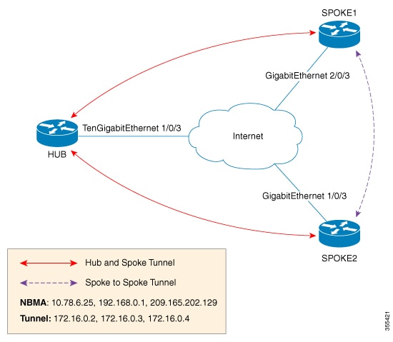
In this figure, each spoke acts as a Next Hop Client (NHC) and is configured with static mapping information (hub’s tunnel IP address and NBMA address) to reach hub which acts as Next Hop Server (NHS). NHCs send Next Hop Resolution Protocol (NHRP) registration request to NHS which allows NHS to learn mapping information of the spoke and form a tunnel (hub and spoke) dynamically.
In addition to NHRP registration of NHCs (spokes) with NHS (hub), NHRP provides the capability for NHC to dynamically discover another NHC on demand and form spoke-to-spoke tunnel. Without this discovery, IP packets traversing from hosts behind one spoke to hosts behind another spoke have to traverse by way of the NHS router. This increases the utilization of the hub's physical bandwidth and CPU to process these packets that come into the hub on the multipoint interface and go right back out the multipoint interface. This is often called hairpinning. With NHRP, systems attached to an NBMA network dynamically learn the NBMA address of the other systems that are part of that network, allowing these systems to directly communicate without requiring traffic to use an intermediate hop. This alleviates the load on the intermediate hop (NHS) and can increase the overall bandwidth of the NBMA network to be greater than the bandwidth of the hub router and effectively creates a full-mesh-capable network without having to discover all possible connections beforehand.
This is called a dynamic-mesh network, where there is a base hub-and-spoke network of NHCs and NHSs for transporting NHRP, dynamic routing protocol information, data traffic, and dynamic direct spoke-to-spoke links that are built when there is data traffic to use the link and torn down when the data traffic stops.
 Feedback