-
null
- Finding Feature Information
- Contents
- Prerequisites for Bidirectional Forwarding Detection
- Restrictions for Bidirectional Forwarding Detection
- Information About Bidirectional Forwarding Detection
- How to Configure Bidirectional Forwarding Detection
- Configuration Examples for Bidirectional Forwarding Detection
- Additional References
Configuring Bidirectional Forwarding Detection

Note![]() Bidirectional Forwarding Detection (BFD) support was introduced
Bidirectional Forwarding Detection (BFD) support was introduced
Starting with Cisco IOS Release IOS 15.1(1)SG, on Supervisor Engine 6-E, Supervisor Engine 6L-E. Starting with Cisco IOS XE 3.5.0E and IOS 15.2(1)E, on Supervisor Engine 7-E, and 7L-E.
Starting with Cisco IOS XE 3.6.0E and IOS 15.2(2)E, on Supervisor Engine 8-E.
Starting with Cisco IOS XE 3.10.0E, on Supervisor Engine 9-E
This document describes how to enable the BFD protocol, which is a detection protocol designed to provide fast forwarding path failure detection times for all media types, encapsulations, topologies, and routing protocols.
BFD provides a consistent failure detection method for network administrators in addition to fast forwarding path failure detection. Because the network administrator can use BFD to detect forwarding path failures at a uniform rate, rather than the variable rates for different routing protocol hello mechanisms, network profiling and planning are simplified, and reconvergence time is more consistent and predictable.
Note For details on all the BFD commands introduced in this chapter, see the URL:
http://www.cisco.com/en/US/docs/ios/iproute_pi/command/reference/iri_book.html
For complete syntax and usage information for the switch commands used in this chapter, see the
Cisco IOS Command Reference Guides for the Catalyst 4500 Series Switch.
If a command is not in the Cisco Catalyst 4500 Series Switch Command Reference , you can locate it in the Cisco IOS Master Command List, All Releases.
Finding Feature Information
Your software release may not support all the features documented in this module. For the latest feature information and caveats, see the release notes for your platform and software release. To find information about the features documented in this module, and to see a list of the releases in which each feature is supported, see the “Technical Assistance” section.
Use Cisco Feature Navigator to find information about platform support and Cisco software image support. To access Cisco Feature Navigator, go to http://www.cisco.com/go/cfn. An account on Cisco.com is not required.
Contents
Prerequisites for Bidirectional Forwarding Detection
- IP routing must be enabled on all participating switches.
- One of the IP routing protocols supported by BFD must be configured on the switches before BFD is deployed. You should implement fast convergence for the routing protocol that you plan to use. See the IP routing documentation for your version of Cisco IOS software for information on configuring fast convergence. See the “Restrictions for Bidirectional Forwarding Detection” section for more information on BFD routing protocol support in Cisco IOS software.
Restrictions for Bidirectional Forwarding Detection
- BFD Hardware offloading of sessions is not supported with the use of authentication on the 4500 Sup7E and Sup8E. Enable BFD Echo mode to work with authentication.
- BFD works only for directly connected neighbors. BFD neighbors must be no more than one IP hop away. Multihop configurations are not supported.
- Catalyst 4500 series switches support up to 128 BFD sessions with a minimum hello interval of 100 ms and a multiplier of 3. The multiplier specifies the minimum number of consecutive packets that can be missed before a session is declared down.
- If SSO is enabled on a dual RP system, the following limitations apply:
–![]() The minimum hello interval is 100 ms with a multiplier of 5 or higher.
The minimum hello interval is 100 ms with a multiplier of 5 or higher.
–![]() Smaller values may be configured but may flap during an SSO switchover.
Smaller values may be configured but may flap during an SSO switchover.
Cisco IOS Release XE 3.5.0E and IOS 15.2(1)E
- Catalyst 4500 series switches support up to 100 BFD sessions with a minimum hello interval of 100 ms and a multiplier of 3. The multiplier specifies the minimum number of consecutive packets that can be missed before a session is declared down.
- If SSO is enabled on a dual RP system, the following limitations apply:
–![]() The minimum hello interval is 100 ms with a multiplier of 5 or higher.
The minimum hello interval is 100 ms with a multiplier of 5 or higher.
–![]() Smaller values may be configured but may flap during an SSO switchover.
Smaller values may be configured but may flap during an SSO switchover.
Note![]() For the most accurate platform and hardware restrictions, see the Cisco IOS software release notes for your software version.
For the most accurate platform and hardware restrictions, see the Cisco IOS software release notes for your software version.
Information About Bidirectional Forwarding Detection
BFD Operation
BFD provides a low-overhead, short-duration method of detecting failures in the forwarding path between two adjacent switches, including the interfaces, data links, and forwarding planes.
BFD is a detection protocol that you enable at the interface and routing protocol levels. Cisco supports the BFD asynchronous mode, which depends on the sending of BFD control packets between two systems to activate and maintain BFD neighbor sessions between switches. Therefore, to create a BFD session, you must configure BFD on both systems (or BFD peers). Once BFD has been enabled on the interfaces and at the router level for the appropriate routing protocols, a BFD session is created, BFD timers are negotiated, and the BFD peers will begin to send BFD control packets to each other at the negotiated interval.
Cisco supports BFD echo mode. Echo packets are sent by the forwarding engine and are forwarded back along the same path to perform detection. The BFD session at the other end does not participate in the actual forwarding of the echo packets. See Configuring BFD Echo Mode for more information.
Neighbor Relationships
BFD provides fast BFD peer failure detection times independently of all media types, encapsulations, topologies, and routing protocols BGP, EIGRP, OSPF, and static routes. By sending rapid failure detection notices to the routing protocols in the local switch to initiate the routing table recalculation process, BFD contributes to greatly reduced overall network convergence time. Figure 41-1 shows a simple network with two switches running OSPF and BFD. When OSPF discovers a neighbor (1) it sends a request to the local BFD process to initiate a BFD neighbor session with the OSPF neighbor routers (2). The BFD neighbor session with the OSPF neighbor router is established (3).
Figure 41-1 Establishing a BFD Neighbor Relationship
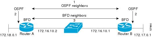
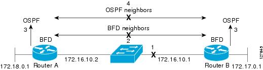
Figure 41-2 shows what happens when a failure occurs in the network (1). The BFD neighbor session with the OSPF neighbor router is torn down (2). BFD notifies the local OSPF process that the BFD neighbor is no longer reachable (3). The local OSPF process tears down the OSPF neighbor relationship (4). If an alternative path is available, the routers will immediately start converging on it.
Figure 41-2 Tearing Down an OSPF Neighbor Relationship
A routing protocol needs to register with BFD for every neighbor it acquires. Once a neighbor is registered, BFD initiates a session with the neighbor if a session does not already exist.
On broadcast interfaces, OSPF establishes a BFD session only with the designated router (DR) and backup designated router (BDR), but not between any two switches (routers) in DROTHER state.
BFD Detection of Failures
Once a BFD session has been established and timer negations are complete, BFD peers send BFD control packets that act in the same manner as an IGP hello protocol to detect liveliness, except at a more accelerated rate. The following information should be noted:
- BFD is a forwarding path failure detection protocol. BFD detects a failure, but the routing protocol must take action to bypass a failed peer.
- Typically, BFD can be used at any protocol layer. However, the Cisco implementation of BFD supports only Layer 3 clients, in particular, the BGP, EIGRP, and OSPF routing protocols, and static routing.
- Cisco devices will use one BFD session for multiple client protocols in the Cisco implementation of BFD. For example, if a network is running OSPF and EIGRP across the same link to the same peer, only one BFD session will be established, and BFD will share session information with both routing protocols. However, IPv4 and IPv6 clients cannot share a BFD session.
BFD Version Interoperability
Starting with Cisco IOS Release 15.1(1)SG, the Catalyst 4500 series switch supports BFD Version 1 as well as BFD Version 0. All BFD sessions come up as Version 1 by default and will be interoperable with Version 0. The system automatically performs BFD version detection, and BFD sessions between neighbors will run in the highest common BFD version between neighbors. For example, if one BFD neighbor is running BFD Version 0 and the other BFD neighbor is running Version 1, the session will run BFD Version 0. The output from the show bfd neighbors [ details ] command will verify which BFD version a BFD neighbor is running.
See the “Example: Configuring BFD in an EIGRP Network with Echo Mode Enabled by Default” section for an example of BFD version detection.
BFD Session Limits
The minimum number of BFD sessions that can be created varies with the “hello” interval. With “hello” intervals of 50ms, 128 sessions are permitted. More sessions are permitted at larger hello intervals.
BFD Support for Nonbroadcast Media Interfaces
Starting with Cisco IOS Release 15.1(1)SG, the BFD feature is supported on VLAN interfaces on the Catalyst 4500 series switch.
The bfd interval command must be configured on an interface to initiate BFD monitoring.
BFD Support for Nonstop Forwarding with Stateful Switchover
Typically, when a networking device restarts, all routing peers of that device detect that the device went down and then came back up. This transition results in a routing flap, which could spread across multiple routing domains. Routing flaps caused by routing restarts create routing instabilities, which are detrimental to the overall network performance. Nonstop forwarding (NSF) helps to suppress routing flaps in devices that are enabled with stateful switchover (SSO), thereby reducing network instability.
NSF allows for the forwarding of data packets to continue along known routes while the routing protocol information is being restored after a switchover. With NSF, peer networking devices do not experience routing flaps. Data traffic is forwarded while the standby RP assumes control from the failed active RP during a switchover. The ability of line cards and forwarding processors to remain up through a switchover and to remain current with the Forwarding Information Base (FIB) on the active RP is key to NSF operation.
In devices that support dual RPs, SSO establishes one of the RPs as the active processor; the other RP is designated as the standby processor, and then synchronizes information between them. A switchover from the active to the standby processor occurs when the active RP fails, when it is removed from the networking device, or when it is manually taken down for maintenance.
BFD Support for Stateful Switchover
The BFD protocol provides short-duration detection of failures in the path between adjacent forwarding engines. In network deployments that use dual RP switches (to provide redundancy), the switches have a graceful restart mechanism that protects the forwarding state during a switchover between the active RP and the standby RP.
Stateful BFD on the Standby RP
To ensure a successful switchover to the standby RP, the BFD protocol uses checkpoint messages to send session information from the active RP Cisco IOS instance to the standby RP Cisco IOS instance. The session information includes local and remote discriminators, adjacent router timer information, BFD setup information, and session-specific information such as the type of session and the session version. In addition, the BFD protocol sends session creation and deletion checkpoint messages to create or delete a session on the standby RP.
The BFD sessions on the standby RP do not receive or send packets and do not process expired timers. These sessions wait for a switchover to occur and then send packets for any active sessions so that sessions do not time out on adjacent switches.
When the BFD protocol on the standby RP is notified of a switchover it changes its state to active, registers itself with Cisco Express Forwarding so that it can receive packets, and then sends packets for any elements that have expired.
BFD also uses checkpoint messages to ensure that sessions created by clients on the active RP are maintained during a switchover. When a switchover occurs, BFD starts an SSO reclaim timer. Clients must reclaim their sessions within the duration specified by the reclaim timer or else the session is deleted.
Timer values are different based on the number of BFD sessions and the platform.
Table 41-1 describes the timer value on Cisco 4500 series switches.
|
|
|
|
|
|
|---|---|---|---|---|
BFD Support for Static Routing
Unlike dynamic routing protocols, such as OSPF and BGP, static routing has no method of peer discovery. Therefore, when BFD is configured, the reachability of the gateway is completely dependent on the state of the BFD session to the specified neighbor. Unless the BFD session is up, the gateway for the static route is considered unreachable, and therefore the affected routes will not be installed in the appropriate Routing Information Base (RIB).
For a BFD session to establish successfully, BFD must be configured on the interface on the peer and there must be a BFD client registered on the peer for the address of the BFD neighbor. When an interface is used by dynamic routing protocols, the latter requirement is usually met by configuring the routing protocol instances on each neighbor for BFD. When an interface is used exclusively for static routing, this requirement must be met by configuring static routes on the peers.
BFD is supported on IPv4 and IPv6 static routes.
Note![]() If a BFD configuration is removed from the remote peer while the BFD session is in the up state, the updated state of the BFD session is not signaled to the static route. This will cause the static route to remain in the RIB. The only workaround is to remove the static route BFD neighbor configuration so that the static route no longer tracks BFD session state.
If a BFD configuration is removed from the remote peer while the BFD session is in the up state, the updated state of the BFD session is not signaled to the static route. This will cause the static route to remain in the RIB. The only workaround is to remove the static route BFD neighbor configuration so that the static route no longer tracks BFD session state.
Benefits of Using BFD for Failure Detection
When you deploy any feature, it is important to consider all the alternatives and be aware of any trade-offs.
The closest alternative to BFD in conventional EIGRP, BGP, and OSPF deployments is the use of modified failure detection mechanisms for EIGRP, BGP, and OSPF routing protocols.
If you set EIGRP hello and hold timers to their absolute minimums, the failure detection rate for EIGRP falls to within a one- to two-second range.
If you use fast hellos for either BGP or OSPF, this Interior Gateway Protocol (IGP) protocol reduces its failure detection mechanism to a minimum of one second.
Advantages to implementing BFD over reduced timer mechanisms for routing protocols include the following:
- Although reducing the EIGRP, BGP, and OSPF timers can result in minimum detection timer of one to two seconds, BFD can provide failure detection in less than one second.
- Because BFD is not tied to any particular routing protocol, it can be used as a generic and consistent failure detection mechanism for EIGRP, BGP, and OSPF.
- Because some parts of BFD can be distributed to the data plane, it can be less CPU-intensive than the reduced EIGRP, BGP, and OSPF timers, which exist wholly at the control plane.
Hardware Support for BFD
The Catalyst 4500 supports a limited number of BFD sessions in hardware. Placing a session in BFD hardware is termed hardware offload. The advantage of hardware offload is that session keep-alive is handled entirely in hardware, placing no load on the CPU.
Not all BFD sessions can be offloaded to hardware. The requirements for offloaded sessions are:
Note![]() BFD Echo is only supported in software and not hardware, because of a limitation on the Catalyst 4500 series switches.
BFD Echo is only supported in software and not hardware, because of a limitation on the Catalyst 4500 series switches.
Note![]() Hardware offload does not work on existing IPv4 static BFD sessions (with BFD Echo enabled). Remove the existing static BFD configuration and reconfigure the static BFD configuration with hardware offload enabled (no BFD Echo) to allow the session to be hosted in hardware.
Hardware offload does not work on existing IPv4 static BFD sessions (with BFD Echo enabled). Remove the existing static BFD configuration and reconfigure the static BFD configuration with hardware offload enabled (no BFD Echo) to allow the session to be hosted in hardware.
The number of offloaded sessions varies by supervisor engine:
WS-X45-SUP6-E, WS-X45-SUP6L-E, support 64 sessions in hardware. Further sessions must be supported in software.
WS-X45-SUP7-E, WS-X45-SUP7L-E, WS-X45-SUP8-E, WS-X45-SUP8L-E, and WS-X45-SUP9-E support all 100 sessions in hardware.
The show bfd neighbor detail command displays print statistics for software and hardware (offloaded) sessions. Hardware sessions provide a limited set of statistics. In particular, statistics for packet transmit and receive intervals are not available for hardware sessions.
The holddown and hello counts are zero for all offloaded sessions.
Note![]() Hardware offload is not supported for IPv6 BFD sessions.
Hardware offload is not supported for IPv6 BFD sessions.
How to Configure Bidirectional Forwarding Detection
You start a BFD process by configuring BFD on the interface. When the BFD process is started, no entries are created in the adjacency database; in other words, no BFD control packets are sent or received. BFD echo mode, which is supported in BFD Version 1, starting with Cisco IOS Release 15.1(1)SG, is enabled by default.
BFD echo packets are sent and received, in addition to BFD control packets. The adjacency creation takes places once you have configured BFD support for the applicable routing protocols. This section contains the following procedures:
- Configuring BFD Session Parameters on the Interface (required)
- Configuring BFD Support for Dynamic Routing Protocols (required)
- Configuring BFD Support for Static Routing (optional)
- Configuring BFD Echo Mode (optional)
- Monitoring and Troubleshooting BFD (optional)
Configuring BFD Session Parameters on the Interface
The steps in this procedure show how to configure BFD on the interface by setting the baseline BFD session parameters on an interface. Repeat the steps in this procedure for each interface over which you want to run BFD sessions to BFD neighbors.
To configure BFD session parameters, perform this task:
Configuring BFD Support for Dynamic Routing Protocols
You can enable BFD support for dynamic routing protocols at the router level to enable BFD support globally for all interfaces or you can configure BFD on a per-interface basis at the interface level.
This section describes the following procedures:
- Configuring BFD Support for BGP (optional)
- Configuring BFD Support for EIGRP (optional)
- Configuring BFD Support for OSPF (optional)
Configuring BFD Support for BGP
This section describes the procedure for configuring BFD support for BGP so that BGP is a registered protocol with BFD and will receive forwarding path detection failure messages from BFD.
Prerequisites
BGP must be running on all participating switches.
The baseline parameters for BFD sessions on the interfaces over which you want to run BFD sessions to BFD neighbors must be configured. See the “Configuring BFD Session Parameters on the Interface” section for more information.
To configure BFD support for BGP, perform this task:
What to Do Next
See the “Monitoring and Troubleshooting BFD” section for more information on monitoring and troubleshooting BFD. If you want to configure BFD support for another routing protocol, see the following sections:
Configuring BFD Support for EIGRP
This section describes the procedure for configuring BFD support for EIGRP so that EIGRP is a registered protocol with BFD and will receive forwarding path detection failure messages from BFD. There are two methods for enabling BFD support for EIGRP:
Prerequisites
EIGRP must be running on all participating switches.
The baseline parameters for BFD sessions on the interfaces over which you want to run BFD sessions to BFD neighbors must be configured. See the “Configuring BFD Session Parameters on the Interface” section for more information.
To configure BFD support for EIGRP, perform this task:
What to Do Next
See the “Monitoring and Troubleshooting BFD” section for more information on monitoring and troubleshooting BFD. If you want to configure BFD support for another routing protocol, see the following sections:
Configuring BFD Support for OSPF
This section describes the procedures for configuring BFD support for OSPF so that OSPF is a registered protocol with BFD and will receive forwarding path detection failure messages from BFD. You can either configure BFD support for OSPF globally on all interfaces or configure it selectively on one or more interfaces.
There are two methods for enabling BFD support for OSPF:
- You can enable BFD on all the interfaces for which OSPF is routing by using the bfd all-interfaces command in router configuration mode. You can disable BFD support on individual interfaces using the ip ospf bfd [ disable ] command in interface configuration mode.
- You can enable BFD on a subset of the interfaces for which OSPF is routing by using the ip ospf bfd command in interface configuration mode.
See the following sections for tasks for configuring BFD support for OSPF:
Configuring BFD Support for OSPF for All Interfaces
To configure BFD for all OSPF interfaces, perform the steps in this section.
If you do not want to configure BFD on all OSPF interfaces and would rather configure BFD support specifically for one or more interfaces, see the “Configuring BFD Support for OSPF for One or More Interfaces” section.
Prerequisites
OSPF must be running on all participating switches.
The baseline parameters for BFD sessions on the interfaces over which you want to run BFD sessions to BFD neighbors must be configured. See the “Configuring BFD Session Parameters on the Interface” section for more information.
To configure BFD support for OSPF for all interfaces:
What to Do Next
See the “Monitoring and Troubleshooting BFD” section for more information on monitoring and troubleshooting BFD. If you want to configure BFD support for another routing protocol, see the following sections:
Configuring BFD Support for OSPF for One or More Interfaces
To configure BFD on one or more OSPF interfaces, perform the steps in this section.
Prerequisites
OSPF must be running on all participating switches.
The baseline parameters for BFD sessions on the interfaces over which you want to run BFD sessions to BFD neighbors must be configured. See the “Configuring BFD Session Parameters on the Interface” section for more information.
To configure BFD supporter for OSPF for one or more interfaces, perform this task:
What to Do Next
See the “Monitoring and Troubleshooting BFD” section for more information on monitoring and troubleshooting BFD. If you want to configure BFD support for another routing protocol, see the following sections:
Configuring BFD Support for Static Routing
Perform this task to configure BFD support for static routing. Repeat the steps in this procedure on each BFD neighbor. For more information, see the “Example: Configuring BFD Support for Static Routing” section.
To configure BFD support for static routing, perform this task:
Configuring BFD Echo Mode
BFD echo mode is enabled by default, but you can disable it such that it can run independently in each direction.
BFD echo mode works with asynchronous BFD. Echo packets are sent by the forwarding engine and forwarded back along the same path in order to perform detection—the BFD session at the other end does not participate in the actual forwarding of the echo packets. The echo function and the forwarding engine are responsible for the detection process; therefore, the number of BFD control packets that are sent out between two BFD neighbors is reduced. In addition, because the forwarding engine is testing the forwarding path on the remote (neighbor) system without involving the remote system, there is an opportunity to improve the interpacket delay variance, thereby achieving quicker failure detection times than when using BFD Version 0 with BFD control packets for the BFD session.
Echo mode is described as without asymmetry when it is running on both sides (both BFD neighbors are running echo mode).
Prerequisites
BFD must be running on all participating switches.
Before using BFD echo mode, you must disable the sending of Internet Control Message Protocol (ICMP) redirect messages by entering the no ip redirects command, to avoid high CPU utilization.
The baseline parameters for BFD sessions on the interfaces over which you want to run BFD sessions to BFD neighbors must be configured. See the “Configuring BFD Session Parameters on the Interface” section for more information.
Restrictions
BFD echo mode which is supported in BFD Version 1.
This section contains the following configuration tasks for BFD echo mode:
Note![]() BFD echo mode does not work in conjunction with Unicast Reverse Path Forwarding (uRPF) configuration. If BFD echo mode and uRPF configurations are enabled, then the sessions will flap.
BFD echo mode does not work in conjunction with Unicast Reverse Path Forwarding (uRPF) configuration. If BFD echo mode and uRPF configurations are enabled, then the sessions will flap.
Configuring the BFD Slow Timer
The steps in this procedure show how to change the value of the BFD slow timer. Repeat the steps in this procedure for each BFD switch.
To configure the BFD slow timer, perform this task:
Disabling BFD Echo Mode Without Asymmetry
The steps in this procedure show how to disable BFD echo mode without asymmetry —no echo packets are sent by the switch, and the switch does not forward BFD echo packets that are received from neighboring switches.
Repeat the steps in this procedure for each BFD switch.
To disable BFD echo mode without asymmetry, perform this task:
|
|
|
|
|---|---|---|
|
|
||
|
|
||
|
|
||
|
|
||
|
|
Exits global configuration mode and returns the switch to global configuration mode. |
Monitoring and Troubleshooting BFD
This section describes how to retrieve BFD information for maintenance and troubleshooting. The commands in these tasks can be entered as needed, in any order.
For more information about BFD session initiation and failure, refer to the “BFD Operation” section.
To monitor and troubleshoot BFD, perform the following steps:
Configuration Examples for Bidirectional Forwarding Detection
This section provides the following configuration examples:
- Example: Configuring BFD in an EIGRP Network with Echo Mode Enabled by Default
- Example: Configuring BFD in an OSPF Network
- Example: Configuring BFD Hardware-Offload support in a BGP Network Network
- Example: Configuring BFD Support for Static Routing
Example: Configuring BFD in an EIGRP Network with Echo Mode Enabled by Default
The following example shows how to configure BFD in an EIGRP network with echo mode enabled by default.
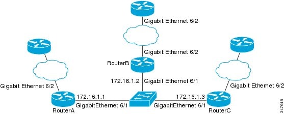
In this example, the EIGRP network contains SwitchA, SwitchB, and SwitchC. Gigabit Ethernet interface 6/1 on SwitchA is connected to the same network as Gigabit Ethernet interface 6/1 on SwitchB. Gigabit Ethernet interface 6/1 on SwitchB is connected to the same network as Gigabit Ethernet interface 6/1 on SwitchC.
SwitchA and SwitchB are running BFD Version 1, which supports echo mode, and SwitchC is running BFD Version 0, which does not support echo mode. We would say that the BFD sessions between SwitchC and its BFD neighbors are running echo mode with asymmetry. This is because echo mode will run on the forwarding path for RouteA and SwitchB, and their echo packets will return along the same path for BFD sessions and failure detections, while their BFD neighbor SwitchC runs BFD Version 0 and uses BFD controls packets for BFD sessions and failure detections.
Figure 41-3 shows a large EIGRP network with several switches, three of which are BFD neighbors that are running EIGRP as their routing protocol.
Figure 41-3 EIGRP Network with Three BFD Neighbors Running V1 or V0
The example, starting in global configuration mode, shows the configuration of BFD.
The output from the show bfd neighbors details command from SwitchA verifies that BFD sessions have been created among all three switches and that EIGRP is registered for BFD support. The first group of output shows that SwitchC with the IP address 172.16.1.3 runs BFD Version 0 and therefore does not use the echo mode. The second group of output shows that SwitchB with the IP address 172.16.1.2 does run BFD Version 1, and the 50 millisecond BFD interval parameter had been adopted.
The relevant command output is shown in bold.
The output from the show bfd neighbors details command on SwitchB verifies that BFD sessions have been created and that EIGRP is registered for BFD support. As previously noted, SwitchA runs BFD Version 1, therefore echo mode is running, and SwitchC runs BFD Version 0, so echo mode does not run. The relevant command output is shown in bold.
Figure 41-4 shows that Gigabit Ethernet interface 6/1 on SwitchB has failed. When Gigabit Ethernet interface 6/1 on SwitchB is shut down, the BFD values of the corresponding BFD sessions on SwitchA and SwitchB are reduced.
Figure 41-4 Gigabit Ethernet Interface 6/1 Failure
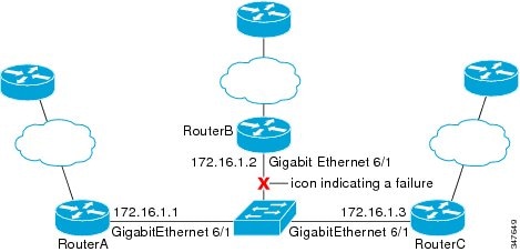
When Gigabit Ethernet interface 6/1 on SwitchB fails, BFD will no longer detect SwitchB as a BFD neighbor for SwitchA or for SwitchC. In this example, Gigabit Ethernet interface 6/1 has been administratively shut down on SwitchB.
The following output from the show bfd neighbors command on SwitchA now shows only one BFD neighbor for SwitchA in the EIGRP network. The relevant command output is shown in bold.
The following output from the show bfd neighbors command on SwitchC also now shows only one BFD neighbor for SwitchC in the EIGRP network. The relevant command output is shown in bold.
Example: Configuring BFD in an OSPF Network
The following example shows how to configure BFD in an OSPF network.
In this example, the “simple” OSPF network consists of SwitchA and SwitchB. Gigabit Ethernet interface 6/1 on SwitchA is connected to the same network as Gigabit Ethernet interface 6/1 in SwitchB. The example, starting in global configuration mode, shows the configuration of BFD. For both SwitchA and SwitchB, BFD is configured globally for all interfaces associated with the OSPF process.
The output from the show bfd neighbors details command verifies that a BFD session has been created and that OSPF is registered for BFD support. The relevant command output is shown in bold.
The output from the show bfd neighbors details command on SwitchB verifies that a BFD session has been created:
The output of the show ip ospf command verifies that BFD has been enabled for OSPF. The relevant command output is shown in bold.
The output of the show ip ospf interface command verifies that BFD has been enabled for OSPF on the interfaces connecting SwitchA and SwitchB. The relevant command output is shown in bold.
Example: Configuring BFD Hardware-Offload support in a BGP Network Network
The following example shows how to configure BFD Hardware-Offload support in a BGP network.
In this example, the “simple” BGP network consists of SwitchA and SwitchB. Gigabit Ethernet interface 6/1 on SwitchA is connected to the same network as Gigabit Ethernet interface 6/1 in SwitchB.
The output from the show bfd neighbors details command from SwitchA verifies that a BFD session has been created and that BGP is registered for BFD support. The relevant command output is shown in bold.
The output from the show bfd neighbors details command on SwitchB verifies that a BFD session has been created:
The output of the show ip bgp neighbors command verifies that BFD has been enabled for the BGP neighbors:
Example: Configuring BFD Support for Static Routing
In the following example, the network consists of SwitchA and SwitchB. Gigabit Ethernet interface 6/1 on SwitchA is connected to the same network as gigabit ethernet interface 6/1 on SwitchB. For the BFD session to come up, SwitchB must be configured.
Note![]() The static route on SwitchB exists solely to enable the BFD session between 10.201.201.1 and 10.201.201.2. If there is no useful static route to configure, select a prefix that will not affect packet forwarding, for example, the address of a locally configured loopback interface.
The static route on SwitchB exists solely to enable the BFD session between 10.201.201.1 and 10.201.201.2. If there is no useful static route to configure, select a prefix that will not affect packet forwarding, for example, the address of a locally configured loopback interface.
Additional References
Related Documents
|
|
|
|---|---|
Cisco BGP Overview” module of the Cisco IOS IP Routing Protocols Configuration Guide |
|
“Configuring EIGRP” module of the Cisco IOS IP Routing Protocols Configuration Guide |
|
“Configuring OSPF” module of the Cisco IOS IP Routing Protocols Configuration Guide |
|
BFD commands: complete command syntax, command mode, command history, defaults, usage guidelines, and examples |
Cisco IOS IP Routing: Protocol-Independent Command Reference |
BGP commands: complete command syntax, command mode, command history, defaults, usage guidelines, and examples |
Cisco IOS IP Routing: Protocol-Independent Command Reference |
EIGRP commands: complete command syntax, command mode, command history, defaults, usage guidelines, and examples |
Cisco IOS IP Routing: Protocol-Independent Command Reference |
OSPF commands: complete command syntax, command mode, command history, defaults, usage guidelines, and examples |
Cisco IOS IP Routing: Protocol-Independent Command Reference |
Standards
|
|
|
|---|---|
BFD for IPv4 and IPv6 (Single Hop), February 2009 |
|
Bidirectional Forwarding Detection, February 2009 |
MIBs
RFCs
|
|
|
|---|---|
No new or modified RFCs are supported by this feature, and support for existing RFCs has not been modified by this feature. |
 Feedback