Information About Configuring Interface Characteristics
Interface Types
This section describes the different types of interfaces supported by the device. The rest of the chapter describes configuration procedures for physical interface characteristics.
 Note |
The stack ports on the rear of the stacking-capable devices are not Ethernet ports and cannot be configured. |
Port-Based VLANs
A VLAN is a switched network that is logically segmented by function, team, or application, without regard to the physical location of the users. Packets received on a port are forwarded only to ports that belong to the same VLAN as the receiving port. Network devices in different VLANs cannot communicate with one another without a Layer 3 device to route traffic between the VLANs.
VLAN partitions provide hard firewalls for traffic in the VLAN, and each VLAN has its own MAC address table. A VLAN comes into existence when a local port is configured to be associated with the VLAN, when the VLAN Trunking Protocol (VTP) learns of its existence from a neighbor on a trunk, or when a user creates a VLAN. VLANs can be formed with ports across the stack.
To configure VLANs, use the vlan vlan-id global configuration command to enter VLAN configuration mode. The VLAN configurations for normal-range VLANs (VLAN IDs 1 to 1005) are saved in the VLAN database. If VTP is version 1 or 2, to configure extended-range VLANs (VLAN IDs 1006 to 4094), you must first set VTP mode to transparent. Extended-range VLANs created in transparent mode are not added to the VLAN database but are saved in the device running configuration. With VTP version 3, you can create extended-range VLANs in client or server mode. These VLANs are saved in the VLAN database.
In a switch stack, the VLAN database is downloaded to all switches in a stack, and all switches in the stack build the same VLAN database. The running configuration and the saved configuration are the same for all switches in a stack.
Add ports to a VLAN by using the switchport interface configuration commands:
-
Identify the interface.
-
For a trunk port, set trunk characteristics, and, if desired, define the VLANs to which it can belong.
-
For an access port, set and define the VLAN to which it belongs.
Switch Ports
Switch ports are Layer 2-only interfaces associated with a physical port. Switch ports belong to one or more VLANs. A switch port can be an access port or a trunk port. You can configure a port as an access port or trunk port or let the Dynamic Trunking Protocol (DTP) operate on a per-port basis to set the switchport mode by negotiating with the port on the other end of the link. switch ports are used for managing the physical interface and associated Layer 2 protocols and do not handle routing or bridging.
Configure switch ports by using the switchport interface configuration commands.
Access Ports
An access port belongs to and carries the traffic of only one VLAN (unless it is configured as a voice VLAN port). Traffic is received and sent in native formats with no VLAN tagging. Traffic arriving on an access port is assumed to belong to the VLAN assigned to the port. If an access port receives a tagged packet (Inter-Switch Link [ISL] or IEEE 802.1Q tagged), the packet is dropped, and the source address is not learned.
The types of access ports supported are:
-
Static access ports are manually assigned to a VLAN (or through a RADIUS server for use with IEEE 802.1x.
You can also configure an access port with an attached Cisco IP Phone to use one VLAN for voice traffic and another VLAN for data traffic from a device attached to the phone.
Trunk Ports
A trunk port carries the traffic of multiple VLANs and by default is a member of all VLANs in the VLAN database.
Although by default, a trunk port is a member of every VLAN known to the VTP, you can limit VLAN membership by configuring an allowed list of VLANs for each trunk port. The list of allowed VLANs does not affect any other port but the associated trunk port. By default, all possible VLANs (VLAN ID 1 to 4094) are in the allowed list. A trunk port can become a member of a VLAN only if VTP knows of the VLAN and if the VLAN is in the enabled state. If VTP learns of a new, enabled VLAN and the VLAN is in the allowed list for a trunk port, the trunk port automatically becomes a member of that VLAN and traffic is forwarded to and from the trunk port for that VLAN. If VTP learns of a new, enabled VLAN that is not in the allowed list for a trunk port, the port does not become a member of the VLAN, and no traffic for the VLAN is forwarded to or from the port.
Tunnel Ports
Tunnel ports are used in IEEE 802.1Q tunneling to segregate the traffic of customers in a service-provider network from other customers who are using the same VLAN number. You configure an asymmetric link from a tunnel port on a service-provider edge switch to an IEEE 802.1Q trunk port on the customer switch. Packets entering the tunnel port on the edge switch, already IEEE 802.1Q-tagged with the customer VLANs, are encapsulated with another layer of an IEEE 802.1Q tag (called the metro tag), containing a VLAN ID unique in the service-provider network, for each customer. The double-tagged packets go through the service-provider network keeping the original customer VLANs separate from those of other customers. At the outbound interface, also a tunnel port, the metro tag is removed, and the original VLAN numbers from the customer network are retrieved.
Tunnel ports cannot be trunk ports or access ports and must belong to a VLAN unique to each customer.
Routed Ports
A routed port is a physical port that acts like a port on a router; it does not have to be connected to a router. A routed port is not associated with a particular VLAN, as is an access port. A routed port behaves like a regular router interface, except that it does not support VLAN subinterfaces. Routed ports can be configured with a Layer 3 routing protocol. A routed port is a Layer 3 interface only and does not support Layer 2 protocols, such as DTP and STP.
Configure routed ports by putting the interface into Layer 3 mode with the no switchport interface configuration command. Then assign an IP address to the port, enable routing, and assign routing protocol characteristics by using the ip routing and router protocol global configuration commands.
Note |
Entering a no switchport interface configuration command shuts down the interface and then re-enables it, which might generate messages on the device to which the interface is connected. When you put an interface that is in Layer 2 mode into Layer 3 mode, the previous configuration information related to the affected interface might be lost. |
The number of routed ports that you can configure is not limited by software. However, the interrelationship between this number and the number of other features being configured might impact CPU performance because of hardware limitations.
Note |
The IP Base imagesupports static routing and the Routing Information Protocol (RIP). For full Layer 3 routing or for fallback bridging, you must enable the IP Services image on the standalone device, or the active device |
Switch Virtual Interfaces
A switch virtual interface (SVI) represents a VLAN of switch ports as one interface to the routing or bridging function in the system. You can associate only one SVI with a VLAN. You configure an SVI for a VLAN only to route between VLANs or to provide IP host connectivity to the device. By default, an SVI is created for the default VLAN (VLAN 1) to permit remote device administration. Additional SVIs must be explicitly configured.
Note |
You cannot delete interface VLAN 1. |
SVIs provide IP host connectivity only to the system. SVIs are created the first time that you enter the vlan interface configuration command for a VLAN interface. The VLAN corresponds to the VLAN tag associated with data frames on an ISL or IEEE 802.1Q encapsulated trunk or the VLAN ID configured for an access port. Configure a VLAN interface for each VLAN for which you want to route traffic, and assign it an IP address.
You can also use the interface range command to configure existing VLAN SVIs within the range. The commands entered under the interface range command are applied to all existing VLAN SVIs within the range. You can enter the command interface range create vlan x - y to create all VLANs in the specified range that do not already exist. When the VLAN interface is created, interface range vlan id can be used to configure the VLAN interface.
Although the switch stack or device supports a total of 1005 VLANs and SVIs, the interrelationship between the number of SVIs and routed ports and the number of other features being configured might impact CPU performance because of hardware limitations.
When you create an SVI, it does not become active until it is associated with a physical port.
SVI Autostate Exclude
The line state of an SVI with multiple ports on a VLAN is in the up state when it meets these conditions:
-
The VLAN exists and is active in the VLAN database on the device
-
The VLAN interface exists and is not administratively down.
-
At least one Layer 2 (access or trunk) port exists, has a link in the up state on this VLAN, and is in the spanning-tree forwarding state on the VLAN.
Note |
The protocol link state for VLAN interfaces come up when the first switchport belonging to the corresponding VLAN link comes up and is in STP forwarding state. |
The default action, when a VLAN has multiple ports, is that the SVI goes down when all ports in the VLAN go down. You can use the SVI autostate exclude feature to configure a port so that it is not included in the SVI line-state up-or-down calculation. For example, if the only active port on the VLAN is a monitoring port, you might configure autostate exclude on that port so that the VLAN goes down when all other ports go down. When enabled on a port, autostate exclude applies to all VLANs that are enabled on that port.
The VLAN interface is brought up when one Layer 2 port in the VLAN has had time to converge (transition from STP listening-learning state to forwarding state). This prevents features such as routing protocols from using the VLAN interface as if it were fully operational and minimizes other problems, such as routing black holes.
EtherChannel Port Groups
EtherChannel port groups treat multiple switch ports as one switch port. These port groups act as a single logical port for high-bandwidth connections between devices or between devices and servers. An EtherChannel balances the traffic load across the links in the channel. If a link within the EtherChannel fails, traffic previously carried over the failed link changes to the remaining links. You can group multiple trunk ports into one logical trunk port, group multiple access ports into one logical access port, group multiple tunnel ports into one logical tunnel port, or group multiple routed ports into one logical routed port. Most protocols operate over either single ports or aggregated switch ports and do not recognize the physical ports within the port group. Exceptions are the DTP, the Cisco Discovery Protocol (CDP), and the Port Aggregation Protocol (PAgP), which operate only on physical ports.
When you configure an EtherChannel, you create a port-channel logical interface and assign an interface to the EtherChannel. For Layer 3 interfaces, you manually create the logical interface by using the interface port-channel global configuration command. Then you manually assign an interface to the EtherChannel by using the channel-group interface configuration command. For Layer 2 interfaces, use the channel-group interface configuration command to dynamically create the port-channel logical interface. This command binds the physical and logical ports together.
10-Gigabit Ethernet Interfaces
A 10-Gigabit Ethernet interface operates only in full-duplex mode. The interface can be configured as a switched or routed port.
The device has a network module slot into which you can insert a 10-Gigabit Ethernet network module, a 1-Gigabit Ethernet network module, or a blank module.
For more information about the Cisco TwinGig Converter Module, see the device hardware installation guide and your transceiver module documentation.
Multigigabit Ethernet
The MultiGigabit Ethernet (mGig) feature allows you to configure speeds of 100 Mbps, 1 Gbps, 2.5 Gbps, and 5 Gbps with automatic bandwidth negotiation over traditional CAT5e cables and higher cable variants.
The following Cisco switches support the mGig feature:
-
WS-C3850-12X48U
-
WS-C3850-24XU
-
10Gbs (downshift to 5Gbs)
-
5Gbs (downshift to 2.5Gbs)
-
2.5Gbs (downshift to 1Gbs)
-
1Gbs (downshift to 100Mbs)
Power over Ethernet
The Power over Ethernet (PoE) technology allows PoE (802.3af standard), PoE+ (802.3at) ports to supply power for the operation of a device.
Cisco Universal Power Over Ethernet (Cisco UPoE) extends the IEEE PoE+ standard to double the power per port to 60 watts.
For more information, see the Configuring PoE section of this guide
Using the Switch USB Ports
The device has two USB ports on the front panel — a USB mini-Type B console port and a USB Type A port.
USB Mini-Type B Console Port
The device has the following console ports:
-
USB mini-Type B console connection
-
RJ-45 console port
Console output appears on devices connected to both ports, but console input is active on only one port at a time. By default, the USB connector takes precedence over the RJ-45 connector.
Note |
Windows PCs require a driver for the USB port. See the hardware installation guide for driver installation instructions. |
Use the supplied USB Type A-to-USB mini-Type B cable to connect a PC or other device to the device. The connected device must include a terminal emulation application. When the device detects a valid USB connection to a powered-on device that supports host functionality (such as a PC), input from the RJ-45 console is immediately disabled, and input from the USB console is enabled. Removing the USB connection immediately reenables input from the RJ-45 console connection. An LED on the device shows which console connection is in use.
Console Port Change Logs
At software startup, a log shows whether the USB or the RJ-45 console is active. Each device in a stack issues this log. Every device always first displays the RJ-45 media type.
In the sample output, Device 1 has a connected USB console cable. Because the bootloader did not change to the USB console, the first log from Device 1 shows the RJ-45 console. A short time later, the console changes and the USB console log appears. Device 2 and Device 3 have connected RJ-45 console cables.
switch-stack-1
*Mar  1 00:01:00.171: %USB_CONSOLE-6-MEDIA_RJ45: Console media-type is RJ45.
*Mar  1 00:01:00.431: %USB_CONSOLE-6-MEDIA_USB: Console media-type is USB.
switch-stack-2
*Mar  1 00:01:09.835: %USB_CONSOLE-6-MEDIA_RJ45: Console media-type is RJ45.

switch-stack-3
*Mar  1 00:01:10.523: %USB_CONSOLE-6-MEDIA_RJ45: Console media-type is RJ45.
When the USB cable is removed or the PC de-activates the USB connection, the hardware automatically changes to the RJ-45 console interface:
switch-stack-1
Mar  1 00:20:48.635: %USB_CONSOLE-6-MEDIA_RJ45: Console media-type is RJ45.
You can configure the console type to always be RJ-45, and you can configure an inactivity timeout for the USB connector.
USB Type A Port
The USB Type A port provides access to external USB flash devices, also known as thumb drives or USB keys. The port supports Cisco USB flash drives with capacities from 128 MB to 8 GB (USB devices with port densities of 128 MB, 256 MB, 1 GB, 4 GB, 8 GB are supported). You can use standard Cisco IOS command- line interface (CLI) commands to read, write, erase, and copy to or from the flash device. You can also configure the device to boot from the USB flash drive.
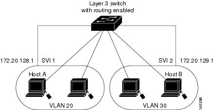
Interface Connections
Devices within a single VLAN can communicate directly through any switch. Ports in different VLANs cannot exchange data without going through a routing device. With a standard Layer 2 device, ports in different VLANs have to exchange information through a router. By using the device with routing enabled, when you configure both VLAN 20 and VLAN 30 with an SVI to which an IP address is assigned, packets can be sent from Host A to Host B directly through the device with no need for an external router.
-
The routing function can be enabled on all SVIs and routed ports. The device routes only IP traffic. When IP routing protocol parameters and address configuration are added to an SVI or routed port, any IP traffic received from these ports is routed.
-
Fallback bridging forwards traffic that the device does not route or traffic belonging to a nonroutable protocol, such as DECnet. Fallback bridging connects multiple VLANs into one bridge domain by bridging between two or more SVIs or routed ports. When configuring fallback bridging, you assign SVIs or routed ports to bridge groups with each SVI or routed port assigned to only one bridge group. All interfaces in the same group belong to the same bridge domain.
Interface Configuration Mode
The device supports these interface types:
-
Physical ports—device ports and routed ports
-
VLANs—switch virtual interfaces
-
Port channels—EtherChannel interfaces
You can also configure a range of interfaces.
To configure a physical interface (port), specify the interface type, stack member number (only stacking-capable switches), module number, and device port number, and enter interface configuration mode.
-
Type—Gigabit Ethernet (gigabitethernet or gi) for 10/100/1000 Mb/s Ethernet ports, 10-Gigabit Ethernet (tengigabitethernet or te) for 10,000 Mb/s, or small form-factor pluggable (SFP) module Gigabit Ethernet interfaces (gigabitethernet or gi).
-
Stack member number—The number that identifies the device within the stack. The device number range is 1 to 9 and is assigned the first time the device initializes. The default device number, before it is integrated into a device stack, is 1. When a device has been assigned a stack member number, it keeps that number until another is assigned to it.
You can use the switch port LEDs in Stack mode to identify the stack member number of a device.
-
Module number—The module or slot number on the device: switch (downlink) ports are 0, and uplink ports are 1.
-
Port number—The interface number on the device. The 10/100/1000 port numbers always begin at 1, starting with the far left port when facing the front of the device, for example, gigabitethernet1/0/1 or gigabitethernet1/0/8.
On a device with SFP uplink ports, the module number is 1 and the port numbers restart. For example, if the device has 24 10/100/1000 ports, the SFP module ports are gigabitethernet1/1/1 through gigabitethernet1/1/4 or tengigabitethernet1/1/1 through tengigabitethernet1/1/4.
You can identify physical interfaces by physically checking the interface location on the device. You can also use the show privileged EXEC commands to display information about a specific interface or all the interfaces on the switch. The remainder of this chapter primarily provides physical interface configuration procedures.
These are examples of how to identify interfaces on a stacking-capable device:
-
To configure 10/100/1000 port 4 on a standalone device, enter this command:
Device(config)# interface gigabitethernet1/0/4 -
To configure 10-Gigabit Ethernet port 1 on a standalone device, enter this command:
Device(config)# interface tengigabitethernet1/0/1 -
To configure 10-Gigabit Ethernet port on stack member 3, enter this command:
Device(config)# interface tengigabitethernet3/0/1 -
To configure the first SFP module (uplink) port on a standalone device, enter this command:
Device(config)# interface gigabitethernet1/1/1
Default Ethernet Interface Configuration
To configure Layer 2 parameters, if the interface is in Layer 3 mode, you must enter the switchport interface configuration command without any parameters to put the interface into Layer 2 mode. This shuts down the interface and then re-enables it, which might generate messages on the device to which the interface is connected. When you put an interface that is in Layer 3 mode into Layer 2 mode, the previous configuration information related to the affected interface might be lost, and the interface is returned to its default configuration.
This table shows the Ethernet interface default configuration, including some features that apply only to Layer 2 interfaces.
|
Feature |
Default Setting |
||
|---|---|---|---|
|
Operating mode |
Layer 2 or switching mode (switchport command). |
||
|
Allowed VLAN range |
VLANs 1– 4094. |
||
|
Default VLAN (for access ports) |
VLAN 1 (Layer 2 interfaces only). |
||
|
Native VLAN (for IEEE 802.1Q trunks) |
VLAN 1 (Layer 2 interfaces only). |
||
|
VLAN trunking |
Switchport mode dynamic auto (supports DTP) (Layer 2 interfaces only). |
||
|
Port enable state |
All ports are enabled. |
||
|
Port description |
None defined. |
||
|
Speed |
Autonegotiate. (Not supported on the 10-Gigabit interfaces.) |
||
|
Duplex mode |
Autonegotiate. (Not supported on the 10-Gigabit interfaces.) |
||
|
Flow control |
Flow control is set to receive: off . It is always off for sent packets. |
||
|
EtherChannel (PAgP) |
Disabled on all Ethernet ports. |
||
|
Port blocking (unknown multicast and unknown unicast traffic) |
Disabled (not blocked) (Layer 2 interfaces only). |
||
|
Broadcast, multicast, and unicast storm control |
Disabled. |
||
|
Protected port |
Disabled (Layer 2 interfaces only). |
||
|
Port security |
Disabled (Layer 2 interfaces only). |
||
|
Port Fast |
Disabled. |
||
|
Auto-MDIX |
Enabled.
|
||
|
Power over Ethernet (PoE) |
Enabled (auto). |
Interface Speed and Duplex Mode
Ethernet interfaces on the switch operate at 10, 100, 1000, or 10,000 Mb/s and in either full- or half-duplex mode. In full-duplex mode, two stations can send and receive traffic at the same time. Normally, 10-Mb/s ports operate in half-duplex mode, which means that stations can either receive or send traffic.
Switch modules include Gigabit Ethernet (10/100/1000-Mb/s) ports, 10-Gigabit Ethernet ports, and small form-factor pluggable (SFP) module slots supporting SFP modules.
Speed and Duplex Configuration Guidelines
When configuring an interface speed and duplex mode, note these guidelines:
-
The 10-Gigabit Ethernet ports do not support the speed and duplex features. These ports operate only at 10,000 Mb/s and in full-duplex mode.
-
Do not disable Auto-Negotiation on PoE switches.
-
Gigabit Ethernet (10/100/1000-Mb/s) ports support all speed options and all duplex options (auto, half, and full). However, Gigabit Ethernet ports operating at 1000 Mb/s do not support half-duplex mode.
- For SFP module ports, the
speed and duplex CLI options change depending on the SFP module type:
-
The 1000BASE-x (where -x is -BX, -CWDM, -LX, -SX, and -ZX) SFP module ports support the nonegotiate keyword in the speed interface configuration command. Duplex options are not supported.
-
The 1000BASE-T SFP module ports support the same speed and duplex options as the 10/100/1000-Mb/s ports.
-
-
-
If both ends of the line support autonegotiation, we highly recommend the default setting of auto negotiation.
-
If one interface supports autonegotiation and the other end does not, configure duplex and speed on both interfaces; do not use the auto setting on the supported side.
-
When STP is enabled and a port is reconfigured, the device can take up to 30 seconds to check for loops. The port LED is amber while STP reconfigures.
-
As best practice, we suggest configuring the speed and duplex options on a link to auto or to fixed on both the ends. If one side of the link is configured to auto and the other side is configured to fixed, the link will not be up and this is expected.
 Caution |
Changing the interface speed and duplex mode configuration might shut down and re-enable the interface during the reconfiguration. |
IEEE 802.3x Flow Control
Flow control enables connected Ethernet ports to control traffic rates during congestion by allowing congested nodes to pause link operation at the other end. If one port experiences congestion and cannot receive any more traffic, it notifies the other port by sending a pause frame to stop sending until the condition clears. Upon receipt of a pause frame, the sending device stops sending any data packets, which prevents any loss of data packets during the congestion period.
Note |
Flow control is not supported on Cisco Catalyst 3650 Series Switches and Cisco Catalyst 3850 Series Switches. |
Note |
The switch ports can receive, but not send, pause frames. |
You use the flowcontrol interface configuration command to set the interface’s ability to receive pause frames to on , off , or desired . The default state is on .
When set to desired , an interface can operate with an attached device that is required to send flow-control packets or with an attached device that is not required to but can send flow-control packets.
These rules apply to flow control settings on the device:
-
receive on (or desired ): The port cannot send pause frames but can operate with an attached device that is required to or can send pause frames; the port can receive pause frames.
-
receive off : Flow control does not operate in either direction. In case of congestion, no indication is given to the link partner, and no pause frames are sent or received by either device.
Layer 3 Interfaces
The device supports these types of Layer 3 interfaces:
-
SVIs: You should configure SVIs for any VLANs for which you want to route traffic. SVIs are created when you enter a VLAN ID following the interface vlan global configuration command. To delete an SVI, use the no interface vlan global configuration command. You cannot delete interface VLAN 1.
Note
When you create an SVI, it does not become active until it is associated with a physical port.
When configuring SVIs, you can also configure SVI autostate exclude on a port in the SVI to exclude that port from being included in determining SVI line-state status.
-
Routed ports: Routed ports are physical ports configured to be in Layer 3 mode by using the no switchport interface configuration command.
-
Layer 3 EtherChannel ports: EtherChannel interfaces made up of routed ports.
A Layer 3 device can have an IP address assigned to each routed port and SVI.
There is no defined limit to the number of SVIs and routed ports that can be configured in a device or in a device stack. However, the interrelationship between the number of SVIs and routed ports and the number of other features being configured might have an impact on CPU usage because of hardware limitations. If the device is using its maximum hardware resources, attempts to create a routed port or SVI have these results:
-
If you try to create a new routed port, the device generates a message that there are not enough resources to convert the interface to a routed port, and the interface remains as a switchport.
-
If you try to create an extended-range VLAN, an error message is generated, and the extended-range VLAN is rejected.
-
If the device is notified by VLAN Trunking Protocol (VTP) of a new VLAN, it sends a message that there are not enough hardware resources available and shuts down the VLAN. The output of the show vlan user EXEC command shows the VLAN in a suspended state.
-
If the device attempts to boot up with a configuration that has more VLANs and routed ports than hardware can support, the VLANs are created, but the routed ports are shut down, and the device sends a message that this was due to insufficient hardware resources.
Note |
All Layer 3 interfaces require an IP address to route traffic. This procedure shows how to configure an interface as a Layer 3 interface and how to assign an IP address to an interface: If the physical port is in Layer 2 mode (the default), you must enter the no switchport interface configuration command to put the interface into Layer 3 mode. Entering a no switchport command disables and then re-enables the interface, which might generate messages on the device to which the interface is connected. Furthermore, when you put an interface that is in Layer 2 mode into Layer 3 mode, the previous configuration information related to the affected interface might be lost, and the interface is returned to its default configuration |
 Feedback