- Prerequisites for Cisco StackWise Virtual
- Restrictions for Cisco StackWise Virtual
- Information About Cisco Stackwise Virtual
- Cisco StackWise Virtual Redundancy
- Multichassis EtherChannels
- Dual-Active Detection
- Implementing Cisco StackWise Virtual
- How to Configure Cisco StackWise Virtual
- Verifying Cisco StackWise Virtual Configuration
- Additional References for Stackwise Virtual
- Feature Information for Cisco StackWise Virtual
Configuring Cisco StackWise Virtual
Prerequisites for Cisco StackWise Virtual
Restrictions for Cisco StackWise Virtual
-
The Federal Information Processing Standards (FIPS) is not supported on Cisco StackWise Virtual links (SVLs).
-
Cisco StackWise Virtual is supported only on the following Cisco Catalyst 3850 Series Switch models.
-
WS-C3850-24XS-S
-
WS-C3850-24XS-E
-
WS-C3850-12XS-S
-
WS-C3850-12XS-E
-
WS-C3850-48XS-S
-
WS-C3850-48XS-E
-
WS-C3850-48XS-F-S
-
WS-C3850-48XS-F-E
-
-
The dual-active and SVL configuration are performed manually and the device should be rebooted for the configuration changes to take effect.
-
Cisco StackWise Virtual is supported in IP services and IP base licenses.The licenses must be matched between two Cisco StackWise Virtual member switches. License migration requires both Cisco StackWise Virtual member switches to be rebooted to activate the licenses.
-
When deploying Cisco StackWise Virtual, ensure that VLAN ID 4094 is not used anywhere on the network. All inter-chassis system control communication between stack members is carried over the reserved VLAN ID 4094 from the global range.
-
4x10G break-out cables are not supported with SVLs.
-
Configuring SVLs on any of the network modules is not supported.
-
Dual-Active Detection is not supported on the uplink ports of the switch.
Information About Cisco Stackwise Virtual
StackWise Virtual Overview
Cisco StackWise Virtual is a network system virtualization technology that pairs two switches into one virtual switch. Switches in a Cisco StackWise Virtual solution simplify operational efficiency with a single control and management plane, scale system bandwidth with distributed forwarding plane, and assist in building resilient networks using the recommended network design. Cisco StackWise Virtual allows two physical switches to operate as a single logical virtual switch using a 40-G or 10-G Ethernet connection.
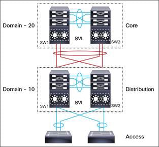
Cisco StackWise Virtual Topology
A typical network design consists of core, distribution, and access layers. The default mode of a switch is standalone. When two redundant switches are deployed in the distribution layer, the following network challenges arise:
-
If VLAN IDs are reused between access layers then, it will introduce a spanning tree loop that will impact the overall performance of the network.
-
Spanning tree protcols and configuration are required to protect Layer 2 network against spanning tree protcol loop, and root and bridge protocol data unit management.
-
Additional protocols such as first hop redundancy protocol are required to virtualize the IP gateway function. This should align with STP root priorities for each VLAN.
-
The Protocol independent multicast designated router (PIM DR) configuration should be fine-tuned to selectively build a multicast forwarding topology on a VLAN.
-
The standalone distribution layer system provides protocol-driven remote failure and detection, which results in slower convergence time. Fine-tune FHRP and PIM timers for rapid fault detection and recovery process.
We recommend the Cisco StackWise Virtual model for aggregation layers and collapsed aggregation and core layers. The Cisco StackWise technology is a technology, which, when extended over Ethernet networks, provides flexibility since the length of the traditional back stack cable is not a limitation anymore. The stack can be formed over a redundant 40-G or 10-G fiber links to ensure that the distribution or the aggregation switches can be deployed over a large distance.
Note that STP keeps one of the ports connected to the distribution switches blocked on the access switches. As a result of this, an active link failure causes STP convergence and the network suffers from traffic loss, flooding, and a possible transient loop in the network. On the other hand, if the switches are logically merged into one switch, all the access switches might form an EtherChannel bundle with distribution switches, and a link failure within an EtherChannel would not have any impact as long as at least one member within the EtherChannel is active.
Etherchannel in StackWise Virtual is capable of implementing MEC across the stack members. When access layer and aggregation layer are collapsed into a single StackWise Virtual system, MEC across the different access layer domain members and across distribution and access layer switches will not be supported. MEC is designed to forward the traffic over the local link irrespective of the hash result.
Since the control plane, management plane, and data plane are integrated, the system behaves as a single switch.
The virtualization of multiple physical switches into a single logical switch is from a control and management plane perspective only. Because of the control plane being common, it may look like a single logical entity to peer switches. The data plane of the switches are distributed. Each switch is capable of forwarding over its local interfaces without involving other members. However, when a packet coming into a switch has to be forwarded over a different member’s port, the forwarding context of the packet is carried over to the destination switch after ingress processing is performed in the ingress switch. Egress processing is done only in the egress switch. This provides a uniform data plane behavior to the entire switch irrespective whether of the destination port is in a local switch or in a remote switch. However, the common control plane ensures that all the switches have equivalent data plane entry for each forwarding entity.
An election mechanism, which elects one of the switches to be Cisco StackWise Virtual active and the other switch to be a control plane standby, is also present. The active switch is responsible for all of the management, bridging and routing protocols, and software data path. These are centralized on the Active Supervisor of a Cisco StackWise Virtual active switch.
Cisco StackWise Virtual member switches talk to each other using a virtual software module called Virtual Communication Manager (VCM) over a StackWise Virtual link.
The following are the components of the Cisco StackWise Virtual solution:
-
Stack members
-
StackWise Virtual link: 10-Gb or 40-Gb Ethernet connections
StackWise Virtual link is the link that connects the switches over Ethernet. Typically, Cisco StackWise Virtual consits of multiple 10-G or 40-G physical links. It carries all the control and data traffic between the switching units. You can configure any physical port as a StackWise Virtual link. When a switch is powered up and the hardware is initiliazed, it looks for a configured StackWise Virtual link before the initilization of the control plane.
Cisco StackWise Virtual Header (SVH) is 64-byte overhead frame that is appended over all control, data, and management plane traffic that traverse over each SVL between the two stack members of the Cisco StackWise Virtual domain. The SVH-encapsulated traffic operates at OSI Layer 2 and can be recognized and processed only by Cisco StackWise Virtual-enabled switches. SVL interfaces are nonbridgeable, and allows nonrouteable traffic over a L2 or L3 network.
Cisco StackWise Virtual Redundancy
Cisco StackWise Virtual operates stateful switchover (SSO) between the active and standby switches. The following are the ways in which Cisco StackWise Virtual's redundancy model differs from that of the standalone mode:
-
The Cisco StackWise Virtual active and standby switches are hosted in separate switches and use a StackWise Virtual link to exchange information.
-
The active switch controls both the switches of Cisco StackWise Virtual. The active switch runs the Layer 2 and Layer 3 control protocols and manages the switching modules of both the switches.
-
The Cisco StackWise Virtual active and standby switches perform data traffic forwarding.
 Note | If the Cisco StackWise Virtual active switch fails, the standby switch initiates a switchover and assumes the Cisco StackWise Virtual active switch role. |
SSO Redundancy
A StackWise Virtual system operates with SSO redundancy if it meets the following requirements:
-
Both the switches must be running the same software version, unless they are in the process of software upgrade.
-
StackWise Virtual link-related configuration in the two switches must match.
-
Non-Stop forwarding (NSF) configuration should not be dependent on building SSO peering.
-
License type must be same on both the switch models.
-
Both the switch models must be in the same StackWise Virtual domain.
With SSO redundancy, the StackWise Virtual standby switch is always ready to assume control if a fault occurs on the StackWise Virtual active switch. Configuration, forwarding, and state information are synchronized from the Stackwise Virtual active switch to the redundant switch at startup, and whenever changes to the StackWise Virtual active switch configuration occur. If a switchover occurs, traffic disruption is minimized.
If StackWise Virtual does not meet the requirements for SSO redundancy, it will be incapable of establishing a relationship with the peer switch. StackWise Virtual runs stateful switchover (SSO) between the StackWise Virtual active and standby switches. The StackWise Virtual determines the role of each switch during initialization.
The CPU in the StackWise Virtual standby switch runs in hot standby state. StackWise Virtual uses a StackWise Virtual link to synchronize configuration data from the StackWise Virtual active switch to the StackWise Virtual standby switch. Also, protocols and features that support high availability synchronize their events and state information to the StackWise Virtual standby switch.
Nonstop Forwarding
While implementing Nonstop Forwarding (NSF) technology in systems using SSO redundancy mode, network disruptions are transparent to campus users and applications. High availability is provided even when the control-plane processing stack-member switch is reset. During a failure of the underlying Layer 3, NSF-capable protocols perform graceful network topology resynchronization. The preset forwarding information on the redundant stack-member switch remains intact; this switch continues to forward the data in the network. This service availability significantly lowers the mean time to repair (MTTR) and increases the mean time between failure (MTBF) to achieve a high level of network availability.
Multichassis EtherChannels
A Multichassis EtherChannel (MEC) is an EtherChannel bundled with physical ports having common characteristics such as speed and duplex, that are distributed across each Cisco StackWise Virtual system. A Cisco StackWise Virtual MEC can connect to any network element that supports EtherChannel (such as a host, server, router, or switch). Cisco StackWise Virtual supports up to 128 MECs deployed in Layer 2 or Layer 3 modes.
In a Cisco StackWise Virtual system, an MEC is an EtherChannel with additional capability; Cisco StackWise Virtual balances the load across the ports in each switch, as in the back stack of the switch. For example, if traffic enters the Cisco StackWise Virtual active switch, the Cisco StackWise Virtual selects an MEC link based on the hash generated from the packet from the Cisco StackWise Virtual active switch.
Each MEC can optionally be configured to support either Cisco PAgP, IEEE LACP, or Static ON mode. We recommend that you implement EtherChannel using Cisco PAgP or LACP with a compatible neighbor. If a remotely connected neighbor such as Cisco Wireless LAN Controller (WLC) does not support this link-bundling protocol, then a Static ON mode can be deployed. These protocols run only on the Cisco StackWise Virtual active switch.
An MEC can support up to eight physical links that can be distributed in any proportion between the Cisco StackWise Virtual active switch and the Cisco StackWise Virtual standby switch. We recommend that you distribute the MEC ports across both switches evenly.
MEC Minimum Latency Load Balancing
The StackWise Virtual environment is designed such that data forwarding always remains within the switch. The Virtual Stack always tries to forward traffic on the locally available links. This is true for both Layer 2 and Layer3 links. The primary motivation for local forwarding is to avoid unnecessarily sending data traffic over the StackWise Virtual link and thus reduce the latency (extra hop over the SVL) and congestion.The bidirectional traffic is load-shared between the two StackWise Virtual members. However, for each StackWise Virtual member, ingress and egress traffic forwarding is based on locally-attached links that are part of MEC. This local forwarding is a key concept in understanding convergence and fault conditions in a StackWise Virtual enabled campus network.
Whenever a packet is received, the destination port is picked based on the hash value calculated for that flow. The destination port can be in the remote switch even if a port in the MEC is available in the local channel. Due to this, you might see the unicast traffic going over a StackWise Virtual link even if one or more of the MEC member ports are in the local switch. Similarly, even multicast traffic is sent over a StackWise Virtual link.
Note | Minimum Latency Load Balancing is not supported in Cisco IOS XE Denali 16.3.3. |
MEC Failure Scenarios
We recommend that you configure a MEC with at least one link to each switch. This configuration ensures that there is always an alternate path for data traffic in case of a switch failure.
The following sections describe issues that may arise and the resulting impact:
Single MEC Link Failure
If a link within a MEC fails (and other links in the MEC are still operational), the MEC redistributes the load among the operational links, as in a regular port.
All MEC Links to the Cisco StackWise Virtual Active Switch Fail
If all the links to the Cisco StackWise Virtual active switch fail, a MEC becomes a regular EtherChannel with operational links to the Cisco StackWise Virtual standby switch.
Data traffic that terminates on the Cisco StackWise Virtual active switch reaches the MEC by crossing a StackWise Virtual link to the Cisco StackWise Virtual standby switch. Control protocols continue to run in the Cisco StackWise Virtual active switch. Protocol messages reach the MEC by crossing a StackWise Virtual link.
All MEC Links Fail
If all the links in an MEC fail, the logical interface for the EtherChannel is set to Unavailable. Layer 2 control protocols perform the same corrective action as for a link-down event on a regular EtherChannel.
On adjacent switches, routing protocols and the Spanning Tree Protocol (STP) perform the same corrective action as for a regular EtherChannel.
Cisco StackWise Virtual Standby Switch Failure
If the Cisco StackWise Virtual standby switch fails, a MEC becomes a regular EtherChannel with operational links on the Cisco StackWise Virtual active switch. Connected peer switches detect the link failures, and adjust their load-balancing algorithms to use only the links to the StackwWise Virtual active switch.
Cisco StackWise Virtual Active Switch Failure
Cisco StackWise Virtual active switch failure results in a stateful switchover (SSO). After the switchover, a MEC is operational on the new Cisco StackWise Virtual active switch. Connected peer switches detect the link failures (to the failed switch), and adjust their load-balancing algorithms to use only the links to the new Cisco StackWise Virtual active switch.
Dual-Active Detection
If the original Cisco StackWise Virtual active switch is still operational, both the switches will now be Cisco StackWise Virtual active switches. This situation is called a dual-active scenario. This scenario can have adverse effects on network stability because both the switches use the same IP addresses, SSH keys, and STP bridge IDs. Cisco StackWise Virtual detects a dual-active scenario and takes recovery action. Dual-active-detection link is the dedicated link used to mitigate this.
If a StackWise Virtual link fails, the Cisco StackWise Virtual standby switch cannot determine the state of the Cisco StackWise Virtual active switch. To ensure that switchover occurs without delay, the Cisco StackWise Virtual standby switch assumes that the Cisco StackWise Virtual active switch has failed and initiates switchover to take over the Cisco StackWise Virtual active role.
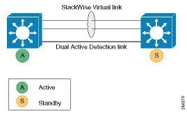
Dual-Active-Detection Link with Fast Hello
To use the dual-active fast hello packet detection method, you must provision a direct ethernet connection between the two Cisco StackWise Virtual switches. You can dedicate up to four links for this purpose.
The two switches periodically exchange special dual-active hello messages containing information about the switch state. If all Stackwise Virtual Links fail and a dual-active scenario occurs, each switch recognizes that there is a dual-active scenario from the peer's messages. This initiates recovery actions as described in the Recovery Actions section. If a switch does not receive an expected dual-active fast hello message from the peer before the timer expires, the switch assumes that the link is no longer capable of dual-active detection.
Note | Do not use the same port for StackWise Virtual link and dual-active detection link. |
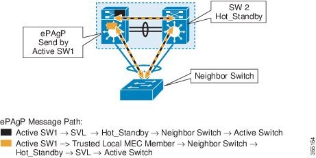
Dual-Active Detection Using Enhanced PAgP
Port aggregation protocol (PAgP) is a Cisco-proprietary protocol for managing EtherChannels. If a Stackwise Virtual MEC terminates to a Cisco switch, you can run PAgP protocol on the MEC. If PAgP is running on the MECs between the Stackwise Virtual and an upstream or downstream switch, the Stackwise Virtual can use PAgP to detect a dual-active scenario. The MEC must have at least one port on each switch of the Stackwise Virtual.
In virtual switch mode, PAgP messages include a new type length value (TLV) which contains the ID of the Stackwise Virtual active switch. Only switches in virtual switch mode send the new TLV.
When the Stackwise Virtual standby switch detects SVL failure, it initiates SSO and becomes Stackwise Virtual active. Subsequent PAgP messages to the connected switch from the newly Stackwise Virtual active switch contain the new Stackwise Virtual active ID. The connected switch sends PAgP messages with the new Stackwise Virtual active ID to both Stackwise Virtual switches.
If the formerly Stackwise Virtual active switch is still operational, it detects the dual-active scenario because the Stackwise Virtual active ID in the PAgP messages changes.
Note | To avoid PAgP flaps and to ensure that dual-active detection functions as expected, the stack MAC persistency wait timer must be configured as indefinite using the command stack-mac persistent timer 0 . |
Recovery Actions
A Cisco Stackwise Virtual active switch that detects a dual-active condition shuts down all of its non-StackWise Virtual Link interfaces to remove itself from the network. The switch then waits in recovery mode until the StackWise Virtual links have been recovered. You should physically repair the StackWise Virtual link failure and the recovery switch should be manually reloaded for it to be the standby switch.
Implementing Cisco StackWise Virtual
The two-node solution of Cisco StackWise Virtual is normally deployed at the aggregation layer. Two switches are connected over a StackWise Virtual link (SVL).
Cisco StackWise Virtual combines the two switches into a single logical switch with a large number of ports, offering a single point of management. One of the member switches is the control and management plane master, while the other one is the standby. The virtualization of multiple physical switches into a single logical switch is only from a control and management perspective. Because of the control plane being common, it may look like a single logical entity to peer switches. The data plane of the switches are converged, that is, the forwarding context of a switch might be passed to the other member switch for further processing when traffic is forwarded across the switches. However, the common control plane ensures that all the switches have equivalent data plane entry for each forwarding entity.
An election mechanism that determines which switch has Cisco StackWise Virtual active and which one is a control plane standby, is available. The active switch is responsible for management, bridging and routing protocols, and software data path. These are centralized on the active switch supervisor of the Cisco StackWise Virtual active switch.
How to Configure Cisco StackWise Virtual
Configuring Cisco StackWise Virtual Settings
To enable StackWise Virtual, perform the following procedure:
After the Cisco StackWise Virtual is enabled and the required interfaces are configured on to Cisco StackWise Virtual links, use the show stackwise-virtual command to verify the configured information. After verification, save the configuration and reboot the switches to form the stack.
Configuring a Cisco StackWise Virtual Link
Note | Cisco StackWise Virtual link is supported on all 10-G interfaces, and 40-G interfaces. However, a combination of both interfaces is not supported. |
To configure a 10 Gigabit Ethernet port as a StackWise Virtual link port, perform the following procedure:
Configuring a StackWise Virtual Dual-Active-Detection link
To configure a 10 Gigabit Ethernet port as StackWise dual-active-detection link, perform the following procedure:
Enabling ePAgP Dual-Active-Detection
To enable ePAgP dual-active-detection on a 10 Gigabit Ethernet, perform the following procedure:
| Command or Action | Purpose | |
|---|---|---|
| Step 1 |
enable
Example:
Device> enable
|
Enables privileged EXEC mode.
|
| Step 2 | configure
terminal
Example: Device# configure terminal | |
| Step 3 | interface TenGigabitEthernet interface
Example: Device(config)#interface TenGigabitEthernet1/0/5
|
Enters a 10-G interface configuration mode. |
| Step 4 | channel-group group_ID mode desirable
Example: Device(config-if)#channel-group 1 mode desirable
| Enables PAgP MEC with channel-group id in the range of 1 to 128 for 10GigabitEthernet interfaces. |
| Step 5 | exit
Example: Device(config-if)#exit
| Exits interface configuration. |
| Step 6 | interface port-channel channel-group-id Example: Device(config)#interface port-channel channel-group-id
| Selects a port channel interface to configure. |
| Step 7 | shutdown Example: Device(config-if)#shutdown
| Shuts down an interface. |
| Step 8 | exit
Example: Device(config-if)#exit
| Exits interface configuration. |
| Step 9 | stackwise-virtual
Example: Device(config)#stackwise-virtual
| Enters the StackWise Virtual configuration mode. |
| Step 10 | dual-active detection pagp
Example: Device(config-stackwise-virtual)#dual-active detection pagp
| Enables pagp dual-active detection. This is enabled by default. |
| Step 11 | dual-active detection pagp trust channel-group channel-group id
Example: Device(config-stackwise-virtual)#dual-active detection pagp trust channel-group 1
| Enables dual-active detection trust mode on channel-group with the configured ID. |
| Step 12 | exit
Example: Device(config-stackwise-virtual)#exit
| Exits the StackWise-Virtual configuration mode. |
| Step 13 | interface port-channel portchannel
Example: Device(config)#interface port-channel 1
|
Configured port-channel on the switch. |
| Step 14 | no shutdown
Example: Device(config-if)#no shutdown
|
Enables the configured port-channel on the switch. |
| Step 15 | exit
Example: Device(config-if)#exit
| Exits interface configuration. |
Disabling Cisco StackWise Virtual
To disable Cisco StackWise Virtual on a switch, perform the following procedure:
| Command or Action | Purpose | |||
|---|---|---|---|---|
| Step 1 |
enable
Example:
Device> enable
|
Enables privileged EXEC mode.
| ||
| Step 2 | configure
terminal
Example: Device# configure terminal | |||
| Step 3 | interface TenGigabitEthernet interface
Example: Device(config)#interface TenGigabitEthernet1/0/41
|
Enters a 10-G interface configuration mode. | ||
| Step 4 | no stackwise-virtual dual-active-detection
Example: Device(config-if)#no stackwise-virtual dual-active-detection
| Dissociates the 10GigabitEthernet interface from Stackwise Virtual dual-active-detection. | ||
| Step 5 | exit
Example: Device(config-if)#exit
| Exits interface configuration. | ||
| Step 6 | interface TenGigabitEthernet interface
Example: Device(config)#interface TenGigabitEthernet1/0/5
|
Enters a 10-G interface configuration mode. | ||
| Step 7 | no stackwise-virtual link link
Example: Device(config-if)#no stackwise-virtual link 1
| Dissociates the 10GigabitEthernet interface from Stackwise Virtual link. | ||
| Step 8 | exit
Example: Device(config-if)#exit
| Exits interface configuration. | ||
| Step 9 | write memory
Example: Device#write memory
| Saves the running configuration.
| ||
| Step 10 | no stackwise-virtual
Example: Device(config)#no stackwise-virtual
| Disables StackWise Virtual configuration. | ||
| Step 11 | exit
Example: Device(config)#exit
| Exits the global configuration mode. | ||
| Step 12 | reload Example: Device(config-if)#reload
|
Restarts the switch. |
Verifying Cisco StackWise Virtual Configuration
To verify your Stackwise Virtual configuration, use the following show commands:
|
show stackwise-virtual switch number <1-2> |
Displays information of a particular switch in the stack. |
|
show stackwise-virtual link |
Displays StackWise Virtual link information. |
|
show stackwise-virtual bandwidth |
Displays the bandwidth available for the Cisco StackWise Virtual. |
|
show stackwise-virtual neighbors |
Displays the Cisco StackWise Virtual neighbors. |
|
show stackwise-virtual dual-active-detection |
Displays Stackwise Virtual dual-active-detection information. |
|
show stackwise-virtual dual-active-detection pagp |
Displays ePAgP dual-active-detection information. |
Additional References for Stackwise Virtual
Related Documents
| Related Topic | Document Title |
|---|---|
|
For complete syntax and usage information for the commands used in this chapter. |
Stack Manager and High Availability Command Reference, Cisco IOS XE Everest 16.6.1 (Catalyst 3850 Switches) |
MIBs
| MIB | MIBs Link |
|---|---|
|
All the supported MIBs for this release. |
To locate and download MIBs for selected platforms, Cisco IOS releases, and feature sets, use Cisco MIB Locator found at the following URL: |
Technical Assistance
| Description | Link |
|---|---|
|
The Cisco Support website provides extensive online resources, including documentation and tools for troubleshooting and resolving technical issues with Cisco products and technologies. To receive security and technical information about your products, you can subscribe to various services, such as the Product Alert Tool (accessed from Field Notices), the Cisco Technical Services Newsletter, and Really Simple Syndication (RSS) Feeds. Access to most tools on the Cisco Support website requires a Cisco.com user ID and password. |
Feature Information for Cisco StackWise Virtual
|
Release |
Modification |
|---|---|
|
Cisco IOS XE Denali 16.3.3 |
This feature was introduced. |
|
Cisco IOS XE Everest 16.5.1a |
This feature was not supported. |
|
Cisco IOS XE Everest 16.6.1 |
This feature was reintroduced. Minimum Latency Load Balancing and Dual-active-detection using ePAgP were introduced. |
 Feedback