Configuring IP Unicast Routing

Information About IP Unicast Routing

This module describes how to configure IPv4 unicast routing on a device.


Note

In addition to IPv4 traffic, you can also enable IPv6 unicast routing and configure interfaces to forward IPv6 traffic


IP Routing Overview

In some network environments, VLANs are associated with individual networks or subnetworks. In an IP network, each subnetwork is mapped to an individual VLAN. Configuring VLANs helps control the size of the broadcast domain and keeps local traffic local. However, network devices in different VLANs cannot communicate with one another without a Layer 3 device (router) to route traffic between the VLAN, referred to as inter-VLAN routing. You configure one or more routers to route traffic to the appropriate destination VLAN.

Figure 1. Routing Topology Example. This figure shows a basic routing topology. Switch A is in VLAN 10, and Switch B is in VLAN 20. The router has an interface in each VLAN.

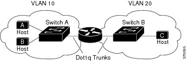
When Host A in VLAN 10 needs to communicate with Host B in VLAN 10, it sends a packet addressed to that host. Switch A forwards the packet directly to Host B, without sending it to the router.

When Host A sends a packet to Host C in VLAN 20, Switch A forwards the packet to the router, which receives the traffic on the VLAN 10 interface. The router checks the routing table, finds the correct outgoing interface, and forwards the packet on the VLAN 20 interface to Switch B. Switch B receives the packet and forwards it to Host C.

Types of Routing

Routers and Layer 3 switches can route packets in these ways:

  • By using default routing

  • By using preprogrammed static routes for the traffic

The switch supports static routes and default routes. It supports RIP for both IPv4 and IPv6 versions.

Static Unicast Routes

Static unicast routes are user-defined routes that cause packets moving between a source and a destination to take a specified path. Static routes can be important if the router cannot build a route to a particular destination and are useful for specifying a gateway of last resort to which all unroutable packets are sent.

The switch retains static routes until you remove them. However, you can override static routes with dynamic routing information by assigning administrative distance values. Each dynamic routing protocol has a default administrative distance, as listed in the following table. If you want a static route to be overridden by information from a dynamic routing protocol, set the administrative distance of the static route higher than that of the dynamic protocol.

Table 1.  Dynamic Routing Protocol Default Administrative Distances

Route Source

Default Distance

Connected interface

0

Static route

1

Enhanced IRGP summary route

5

RIP

120

Unknown

225

Static routes that point to an interface are advertised through RIP and other dynamic routing protocols, whether or not static redistribute router configuration commands were specified for those routing protocols. These static routes are advertised because static routes that point to an interface are considered in the routing table to be connected and hence lose their static nature. However, if you define a static route to an interface that is not one of the networks defined in a network command, no dynamic routing protocols advertise the route unless a redistribute static command is specified for these protocols.

When an interface goes down, all static routes through that interface are removed from the IP routing table. When the software can no longer find a valid next hop for the address specified as the forwarding router's address in a static route, the static route is also removed from the IP routing table.

Default Routes and Networks

A router might not be able to learn the routes to all other networks. To provide complete routing capability, you can use some routers as smart routers and give the remaining routers default routes to the smart router. (Smart routers have routing table information for the entire internetwork.) These default routes can be dynamically learned or can be configured in the individual routers. Most dynamic interior routing protocols include a mechanism for causing a smart router to generate dynamic default information that is then forwarded to other routers.

If a router has a directly connected interface to the specified default network, the dynamic routing protocols running on that device generate a default route. In RIP, it advertises the pseudonetwork 0.0.0.0.

A router that is generating the default for a network also might need a default of its own. One way a router can generate its own default is to specify a static route to the network 0.0.0.0 through the appropriate device.

When default information is passed through a dynamic routing protocol, no further configuration is required. The system periodically scans its routing table to choose the optimal default network as its default route. In Interior Gateway Routing Protocol (IGRP) networks, there might be several candidate networks for the system default. Cisco routers use administrative distance and metric information to set the default route or the gateway of last resort.

If dynamic default information is not being passed to the system, candidates for the default route are specified with the ip default-network global configuration command. If this network appears in the routing table from any source, it is flagged as a possible choice for the default route. If the router has no interface on the default network, but does have a path to it, the network is considered as a possible candidate, and the gateway to the best default path becomes the gateway of last resort.

Routing Information Protocol

The Routing Information Protocol (RIP) is an Interior Gateway Protocol (IGP) created for use in small, homogeneous networks. It is a distance-vector routing protocol that uses broadcast UDP data packets to exchange routing information. The protocol is documented in RFC 1058. You can find detailed information about RIP in IP Routing Fundamentals, published by Cisco Press.

Using RIP, a device sends routing information updates (advertisements) every 30 seconds. If a router does not receive an update from another router for 180 seconds or more, it marks the routes served by that router as unusable. If there is still no update after 240 seconds, the router removes all routing table entries for the non-updating router.

RIP uses hop counts to rate the value of different routes. The hop count is the number of routers that can be traversed in a route. A directly connected network has a hop count of zero; a network with a hop count of 16 is unreachable. This small range (0 to 15) makes RIP unsuitable for large networks.

If the router has a default network path, RIP advertises a route that links the router to the pseudonetwork 0.0.0.0. The 0.0.0.0 network does not exist; it is treated by RIP as a network to implement the default routing feature. The device advertises the default network if a default was learned by RIP or if the router has a gateway of last resort and RIP is configured with a default metric. RIP sends updates to the interfaces in specified networks. If an interface’s network is not specified, it is not advertised in any RIP update.

Default RIP Configuration

Table 2. Default RIP Configuration

Feature

Default Setting

Auto summary

Enabled.

Default-information originate

Disabled.

Default metric

Built-in; automatic metric translations.

IP RIP authentication key-chain

No authentication.

Authentication mode: clear text.

IP RIP triggered

Disabled

IP split horizon

Varies with media.

Neighbor

None defined.

Network

None specified.

Offset list

Disabled.

Output delay

0 milliseconds.

Timers basic

  • Update: 30 seconds.

  • Invalid: 180 seconds.

  • Hold-down: 180 seconds.

  • Flush: 240 seconds.

Validate-update-source

Enabled.

Version

Receives RIP Version 1 and 2 packets; sends Version 1 packets.

How to Enable IP Unicast Routing

By default, IP routing is disabled on a device.

In these procedures, the specified interface can be a switch virtual interface (SVI)-a VLAN interface or a physical port interface created by using the interface vlan vlan_id or interface type number commands respectively, and by default a Layer 3 interface. All Layer 3 interfaces on which routing will occur must have IP addresses assigned to them.


Note

The device supports 16 static routes (including user-configured routes and the default route) and any directly connected routes and default routes for the management interface.


Procedures for configuring routing:

  • To support VLAN interfaces, create and configure VLANs on the device, and assign VLAN membership to Layer 2 interfaces.

  • Configure Layer 3 interfaces.

  • Enable IP routing on the device.

  • Assign IP addresses to the Layer 3 interfaces.

  • Configure static routes.

Enabling IP Unicast Routing

By default, the device is in Layer 2 switching mode and IP routing is disabled. To use the Layer 3 capabilities of the device, you must enable IP routing.

Procedure

  Command or Action Purpose
Step 1

enable

Example:


Device> enable

Enables privileged EXEC mode.

  • Enter your password if prompted.

Step 2

configure terminal

Example:


Device# configure terminal

Enters global configuration mode.

Step 3

ip routing

Example:


Device(config)# ip routing

Enables IP routing.

Step 4

end

Example:


Device(config)# end

Exits global configuration mode and returns to privileged EXEC mode.

Assigning IP Addresses to SVIs

To configure IP routing, you need to assign IP addresses to Layer 3 network interfaces. This enables communication with the hosts of those interfaces that use IP. IP routing is disabled by default, and no IP addresses are assigned to SVIs.

An IP address identifies a location to which IP packets can be sent. Some IP addresses are reserved for special uses and cannot be used for host, subnet, or network addresses. RFC 1166, “Internet Numbers,” contains the official description of IP addresses.

An interface can have one primary IP address. A mask identifies the bits that denote the network number in an IP address. When you use the mask to subnet a network, the mask is referred to as a subnet mask. To receive an assigned network number, contact your Internet service provider.

Follow these steps to assign an IP address and a network mask to an SVI:

Procedure

  Command or Action Purpose
Step 1

enable

Example:


Device> enable

Enables privileged EXEC mode.

  • Enter your password if prompted.

Step 2

configure terminal

Example:


Device# configure terminal

Enters global configuration mode.

Step 3

interface vlan vlan-id

Example:


Device(config)# interface vlan 1

Enters interface configuration mode, and specifies the Layer 3 VLAN to configure.

Step 4

ip address ip-address subnet-mask

Example:


Device(config-if)# ip address 10.1.5.1 255.255.255.0

Configures the IP address and IP subnet mask.

Step 5

end

Example:


Device(config-if)# end

Exits interface configuration mode and returns to privileged EXEC mode.

Step 6

show interfaces vlan [vlan-id]

Example:


Device# show interfaces vlan 4

Displays statistics for all VLAN interfaces configured on the device.

Configuring Default Routes and Networks

Procedure

  Command or Action Purpose
Step 1

enable

Example:


Device> enable

Enables privileged EXEC mode.

  • Enter your password if prompted.

Step 2

configure terminal

Example:


Device# configure terminal

Enters global configuration mode.

Step 3

ip route network number

Example:


(config)# ip route 0.0.0.0 0.0.0.0 10.10.10.2

Specifies a default network.

Step 4

end

Example:


Device(config)# end

Exits global configuration mode and returns to privileged EXEC mode.

Step 5

show ip route

Example:


Device# show ip route

Displays the selected default route in the gateway of last resort display.

Configuring Basic RIP Parameters

To configure RIP, you enable RIP routing for a network and optionally configure other parameters. On the device, RIP configuration commands are ignored until you configure the network number.

Procedure

  Command or Action Purpose
Step 1

enable

Example:


Device> enable

Enables privileged EXEC mode.

  • Enter your password if prompted.

Step 2

configure terminal

Example:


Device# configure terminal

Enters global configuration mode.

Step 3

ip routing

Example:


Device(config)# ip routing

Enables IP routing. (Required only if IP routing is disabled.)

Step 4

router rip

Example:


Device(config)# router rip

Enables a RIP routing process, and enters router configuration mode.

Step 5

network network number

Example:


Device(config-router)# network 10.0.0.0

Associates a network with a RIP routing process. You can specify multiple network commands. RIP routing updates are sent and received through interfaces only on these networks.

Note 

You must configure a network number for the RIP commands to take effect.

Step 6

neighbor ip-address

Example:


Device(config-router)# neighbor 10.2.5.1

(Optional) Defines a neighboring router with which to exchange routing information. This step allows routing updates from RIP (normally a broadcast protocol) to reach nonbroadcast networks.

Step 7

offset-list [access-list number | name] {in | out} offset [type number]

Example:


Device(config-router)# offset-list 103 in 10

(Optional) Applies an offset list to routing metrics to increase incoming and outgoing metrics to routes learned through RIP. You can limit the offset list with an access list or an interface.

Step 8

timers basic update invalid holddown flush

Example:


Device(config-router)# timers basic 45 360 400 300

(Optional) Adjusts routing protocol timers. Valid ranges for all timers are 0 to 4294967295 seconds.

  • update : The time between sending routing updates. The default is 30 seconds.

  • invalid : The timer after which a route is declared invalid. The default is 180 seconds.

  • holddown : The time before a route is removed from the routing table. The default is 180 seconds.

  • flush : The amount of time for which routing updates are postponed. The default is 240 seconds.

Step 9

version {1 | 2}

Example:


Device(config-router)# version 2

(Optional) Configures the switch to receive and send only RIP Version 1 or RIP Version 2 packets. By default, the switch receives Version 1 and 2 but sends only Version 1. 
You can also use the interface commands ip rip {send | receive} version 1 | 2 | 1 2} to control what versions are used for sending and receiving on interfaces.

Step 10

no auto summary

Example:


Device(config-router)# no auto summary

(Optional) Disables automatic summarization. By default, the switch summarizes subprefixes when crossing classful network boundaries. Disable summarization (RIP Version 2 only) to advertise subnet and host routing information to classful network boundaries.

Step 11

end

Example:


Device(config-router)# end

Exits router configuration mode and returns to privileged EXEC mode.

Step 12

show ip protocols

Example:


Device# show ip protocols

Displays the parameters and the current state of the active routing protocol process.

Configuring RIP Authentication

RIP Version 1 does not support authentication. If you are sending and receiving RIP Version 2 packets, you can enable RIP authentication on an interface. The key chain specifies the set of keys that can be used on the interface. If a key chain is not configured, no authentication is performed, not even the default.

The device supports two modes of authentication on interfaces for which RIP authentication is enabled: plain text and MD5. The default is plain text.

Procedure

  Command or Action Purpose
Step 1

enable

Example:


Device> enable

Enables privileged EXEC mode.

  • Enter your password if prompted.

Step 2

configure terminal

Example:


Device# configure terminal

Enters global configuration mode.

Step 3

interface interface-id

Example:

Device(config)# interface gigabitethernet 1/0/1
Or
Device(config)# interface fastethernet 1/0/1

Configures the interface and enters interface configuration mode.

Step 4

ip rip authentication key-chain name-of-chain

Example:


Device(config-if)# ip rip authentication key-chain trees

Enables RIP authentication.

Step 5

ip rip authentication mode {text | md5}

Example:


Device(config-if)# ip rip authentication mode md5

Configures the interface to use plain text authentication (the default) or MD5 digest authentication.

Step 6

end

Example:


Device(config-if)# end

Exits interface configuration mode and returns to privileged EXEC mode.

Monitoring and Maintaining the IP Network

Use the following commands to display specific statistics.

Table 3. Commands to Clear IP Routes or Display Route Status
Command Purpose

show ip route [address [mask] [longer-prefixes]]

Displays the current state of the routing table.

show ip route summary

Displays the current state of the routing table in summary form.

Configuration Examples for IP Unicast Routing

Example: Enabling IP Unicast Routing

This example shows how to enable IP unicast routing.

Device> enable
Device# configure terminal
Device(config)# ip routing
Device(config)# end

Example: Assigning IP Addresses to SVIs

This example shows how to assign an IP address and a network mask to an SVI.


Device> enable
Device# configure terminal
Device(config)# interface vlan 4
Device(config-if)# ip address 10.1.5.1 255.255.255.0
Device(config-if)# exit
Device# show interfaces vlan 4

Example: Displaying Current Status of the Routing Table

This following is sample output from the show ip route command:


Device# show ip route

Codes: L - local, C - connected, S - static, R - RIP, M - mobile, B - BGP
D - EIGRP, EX - EIGRP external, O - OSPF, IA - OSPF inter area 
N1 - OSPF NSSA external type 1, N2 - OSPF NSSA external type 2
E1 - OSPF external type 1, E2 - OSPF external type 2
i - IS-IS, su - IS-IS summary, L1 - IS-IS level-1, L2 - IS-IS level-2
ia - IS-IS inter area, * - candidate default, U - per-user static route
o - ODR, P - periodic downloaded static route, H - NHRP, l - LISP
a - application route
+ - replicated route, % - next hop override, p - overrides from PfR

Gateway of last resort is 192.0.2.5 to network 0.0.0.0

S* 0.0.0.0/0 [0/0] via 192.0.2.5
10.0.0.0/8 is variably subnetted, 2 subnets, 2 masks
C 10.3.3.0/24 is directly connected, GigabitEthernet1/0/23
L 10.3.3.2/32 is directly connected, GigabitEthernet1/0/23
172.16.0.0/24 is subnetted, 1 subnets
S 172.16.0.1 [1/0] via 192.0.2.5
10.0.0.0/8 is variably subnetted, 2 subnets, 2 masks
C 192.0.2.4/24 is directly connected, Vlan1
L 192.0.2.10/24 is directly connected, Vlan1
209.165.201.0/24 is subnetted, 1 subnets
S 209.165.201.1 [1/0] via 192.0.2.5
Device# 


S -- Stand for static route.

Additional References

Related Documents

Related Topic

Document Title

For complete syntax and usage information for the commands used in this chapter.

Consolidated Platform Command Reference, Cisco IOS Release 15.2(7)Ex (Catalyst 1000 Switches)

Technical Assistance

Description Link

The Cisco Support website provides extensive online resources, including documentation and tools for troubleshooting and resolving technical issues with Cisco products and technologies.

To receive security and technical information about your products, you can subscribe to various services, such as the Product Alert Tool (accessed from Field Notices), the Cisco Technical Services Newsletter, and Really Simple Syndication (RSS) Feeds.

Access to most tools on the Cisco Support website requires a Cisco.com user ID and password.

http://www.cisco.com/support

Feature Information for IP Unicast Routing

The following table provides release information about the feature or features described in this module. This table lists only the software release that introduced support for a given feature in a given software release train. Unless noted otherwise, subsequent releases of that software release train also support that feature.

Use the Cisco Feature Navigator to find information about platform support and Cisco software image support. To access Cisco Feature Navigator, go to www.cisco.com/go/cfn. An account on Cisco.com is not required.
Table 4. Feature Information for IP Unicast Routing

Feature Name

Releases

Feature Information

IP Unicast Routing

Cisco IOS Release 15.2(7)E1

This feature was introduced.