Introduction
This chapter provides an overview of the purpose and methodology of this document. This chapter contains the following sections:
•![]() Purpose and Scope of Nexus Validation Test
Purpose and Scope of Nexus Validation Test
•![]() Description of the Test Network
Description of the Test Network
•![]() Features Deployed and Verified
Features Deployed and Verified
Purpose and Scope of Nexus Validation Test
Cisco Nexus 7000 hardware and software releases must pass Cisco's comprehensive quality assurance process, which includes a multistage approach comprising extensive unit test, feature test, and system-level test. Each successive stage in the process adds increasingly higher levels of complexity in a multidimensional mix of features and topology.
NVT has been established as an additional quality assurance stage in order to leverage customer feedback and requirements into the product development cycle. NVT will validate and publish guidelines for deploying Nexus 7000 and NX-OS solutions for datacenter networks.
This document describes the first phase of NVT, which includes IOS to NX-OS migration. The Nexus 7000 is featured throughout the multi-tiered test network topology at every Places-in-the-Network (PIN). IOS on Catalyst 6k and 4k are also deployed side-by-side with the Nexus 7000 to ensure that customers with IOS experience will be able to successfully transition to NX-OS platforms. NVT will provide recommendations and guidelines to ensure that the hardware and features used in this network will behave and perform similarly between the platforms.
Platforms and Releases
The migration testing described in this document incorporates the following platforms and releases:

Note ![]() Any reference to IOS or NX-OS in this document applies only to the software versions and platforms mentioned in the preceding table.
Any reference to IOS or NX-OS in this document applies only to the software versions and platforms mentioned in the preceding table.
Description of the Test Network
Hierarchical Network Model
The test network is a traditional hierarchical model comprising the edge, core, aggregation, and access layers, as shown in the following figure.
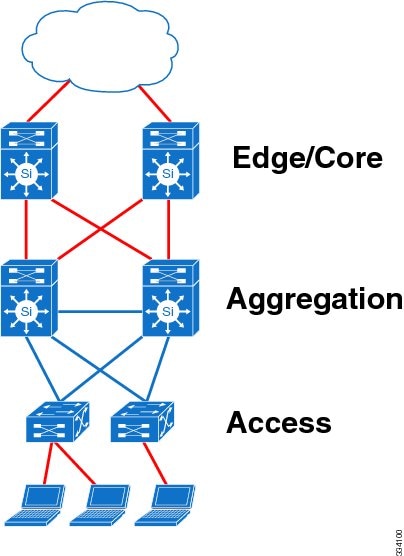
Because most features of interest in the initial phase of testing involve the aggregation layer, the edge and core layers are collapsed into a single layer.
Topology of the Test Network
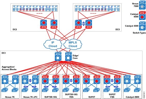
The following figure illustrates the test network topology, consisting of three datacenter sites interconnected through a public IP cloud and an MPLS cloud. The mixture of cross-platform devices presented in this topology is intended for the purpose of migration and interoperability testing.
Edge/Core Layer
The edge layer provides connectivity and security between the datacenter and the public network. This layer also provides private extensions between datacenters through the public cloud. In the test network, private extensions between the datacenters are implemented with GRE tunnels and MPLS VPNs at the edge.
The edge/core layer provides routing and high bandwidth connectivity between the edge and the aggregation layers.
The edge layer of each datacenter in the test network is implemented using one of the following three platform types to ensure feature parity and interoperability:
•![]() Cisco Nexus 7000 Series Switch
Cisco Nexus 7000 Series Switch
•![]() Cisco Catalyst 6500 Series Switch
Cisco Catalyst 6500 Series Switch
•![]() Cisco Catalyst 6500 Series Switch Virtual Switching System (VSS)
Cisco Catalyst 6500 Series Switch Virtual Switching System (VSS)
The use of three different platforms at the edge/core allows for the comparison of feature behavior, performance, and scale between Catalyst 6500 and Nexus 7000 systems operating at the edge/core layers.
Aggregation Layer
The aggregation layer provides connectivity and policy services for traffic flows of all switches within the access-aggregation block.
The aggregation layer of each datacenter consists of seven blocks, implemented using each of these seven platforms:
•![]() Block 1: Cisco Nexus 7000 Series Switch
Block 1: Cisco Nexus 7000 Series Switch
•![]() Block 2: Cisco Nexus 7000 Series Switch with virtual port channel (vPC)
Block 2: Cisco Nexus 7000 Series Switch with virtual port channel (vPC)
•![]() Block 3: Cisco Catalyst 6500 Series Switch Supervisor Engine 720
Block 3: Cisco Catalyst 6500 Series Switch Supervisor Engine 720
•![]() Block 4: Cisco Catalyst 6500 Series Switch Supervisor Engine 720-10G VSS
Block 4: Cisco Catalyst 6500 Series Switch Supervisor Engine 720-10G VSS
•![]() Block 5: Cisco Catalyst 6500 Series Switch Supervisor Engine 2T
Block 5: Cisco Catalyst 6500 Series Switch Supervisor Engine 2T
•![]() Block 6: Cisco Catalyst 6500 Series Switch Supervisor Engine 2T VSS
Block 6: Cisco Catalyst 6500 Series Switch Supervisor Engine 2T VSS
•![]() Block 7: Cisco Catalyst 4500 Series Switch
Block 7: Cisco Catalyst 4500 Series Switch
The aggregation layer of each datacenter is identical in design to the others to ensure that each of the core platforms interoperates well with all major Cisco modular switching products. The common design allows for the comparison of feature behavior, performance, and scale among the major Cisco modular switching products operating at the aggregation layers.
Access Layer
The access layer provides connectivity to a scaled number of end devices in the datacenter network.
In the test network, the access layer is deployed using various Cisco Catalyst switching products.
The migration of the access layer from IOS to NX-OS devices is not covered in this phase of NVT.
Test Network Configuration
The following configuration details are applied to the test network:
•![]() In order to maximize the number of features and protocols that can be tested in parallel, MPLS Multi-VRF (VRF-lite) is deployed across all datacenters.
In order to maximize the number of features and protocols that can be tested in parallel, MPLS Multi-VRF (VRF-lite) is deployed across all datacenters.
•![]() Each datacenter has four VPN routing and forwarding instances (VRFs), with each VRF running one of the following protocols for unicast routing: OSPF, EIGRP, IS-IS, and BGP. For multicast routing, each VRF runs PIM ASM, Bidir, and SSM.
Each datacenter has four VPN routing and forwarding instances (VRFs), with each VRF running one of the following protocols for unicast routing: OSPF, EIGRP, IS-IS, and BGP. For multicast routing, each VRF runs PIM ASM, Bidir, and SSM.
Note ![]() For vPC configuration, PIM Bidir and SSM are not supported and are therefore not tested.
For vPC configuration, PIM Bidir and SSM are not supported and are therefore not tested.
•![]() The Nexus 7000 are further virtualized at the device level using Virtual Device Contexts (VDC).
The Nexus 7000 are further virtualized at the device level using Virtual Device Contexts (VDC).
•![]() The entire test network is configured to support SSO/NSF.
The entire test network is configured to support SSO/NSF.
•![]() The test network is configured and operating in both IPv4 and IPv6 modes. In this phase, the primary focus of the test cases is IPv4.
The test network is configured and operating in both IPv4 and IPv6 modes. In this phase, the primary focus of the test cases is IPv4.
•![]() Bidirectional Forwarding Detection (BFD) is recommended on the Nexus 7000 to optimize network peer failure detection. However, within the test network topology, aggressive timers for routing protocols are used on interfaces where BFD is not supported. For example, BFD is not supported on port-channels and SVIs on Catalyst switches. Otherwise, BFD is used with protocol clients running with default timers.
Bidirectional Forwarding Detection (BFD) is recommended on the Nexus 7000 to optimize network peer failure detection. However, within the test network topology, aggressive timers for routing protocols are used on interfaces where BFD is not supported. For example, BFD is not supported on port-channels and SVIs on Catalyst switches. Otherwise, BFD is used with protocol clients running with default timers.
PIM and First Hop Redundancy Protocol (FHRP) are not supported as BFD clients on the Catalyst 6500 and 4500. Within the NVT topology, even though BFD is configured on routed interfaces between Catalyst switches and the Nexus 7000, the multicast routing protocols were not tested as BFD clients. Therefore, PIM is tested with aggressive timers on those interfaces.
The BFD retransmit interval is configured to be 1 second with 3x holddown multiplier. These parameters are chosen to match the protocols running aggressive timers with 1 second hello intervals.
Note ![]() Disable Internet Control Message Protocol (ICMP) redirect messages on BFD-enabled interfaces.
Disable Internet Control Message Protocol (ICMP) redirect messages on BFD-enabled interfaces.
Features Deployed and Verified
Features relevant to the datacenter edge, core, aggregation, and access layers were tested and verified. Any issues affecting operation and differences between NX-OS and IOS that were not resolved are noted in the subsequent sections.
Edge Layer
Route-Map Based Policies
From the data center edge to the IP and MPLS clouds, route-map based policies control route redistribution between the datacenter IGP and BGP peerings.
The configuration of BGP neighbors is grouped and ordered differently between IOS and NX-OS. Similarly, configurations for other features are more hierarchically structured in NX-OS relative to IOS.
Note ![]() In the route-map definition, NX-OS supports only prefix lists, while IOS supports prefix lists and access lists.
In the route-map definition, NX-OS supports only prefix lists, while IOS supports prefix lists and access lists.
Security ACLs
Security ACLs are used to regulate data flows and control-plane traffic entering and leaving the data centers.
The storage of ACE sequence numbers differs between IOS and NX-OS:
•![]() IOS—The access-list definition does not retain and store the ACE sequence numbers in persistent storage; however, the configured sequence is maintained.
IOS—The access-list definition does not retain and store the ACE sequence numbers in persistent storage; however, the configured sequence is maintained.
•![]() NX-OS—The ACE sequence numbers are stored as a part of the startup configuration.
NX-OS—The ACE sequence numbers are stored as a part of the startup configuration.
The following example shows that the IOS system (Cat-6500) does not store the ACE sequence numbers in the configuration while the NX-OS system (Nexus-7000) stores the numbers.
Cat-6500# show ip access-lists nvt
Extended IP access list nvt
10 permit ip any 230.81.1.0 0.0.0.255
20 permit ip any 230.82.1.0 0.0.0.255
Cat-6500# show running-config | begin nvt
ip access-list extended nvt
permit ip any 230.81.1.0 0.0.0.255 <- Sequence number is not retained
permit ip any 230.82.1.0 0.0.0.255
Nexus-7000# show ip access-lists nvt
IP access list nvt
10 permit ip any 230.81.1.0/24
20 permit ip any 230.82.1.0/24
Nexus-7000# show running-config | begin nvt
ip access-list nvt
10 permit ip any 230.81.1.0/24 <- Sequence number is retained
20 permit ip any 230.82.1.0/24
NetFlow Data Export
Support for NetFlow data export versions differs between the tested switching platforms:
•![]() Catalyst Supervisor Engine 720 supports NetFlow data export versions 5 and 7.
Catalyst Supervisor Engine 720 supports NetFlow data export versions 5 and 7.
•![]() Catalyst Supervisor Engine 2T supports NetFlow data export versions 5 and 9.
Catalyst Supervisor Engine 2T supports NetFlow data export versions 5 and 9.
•![]() Catalyst 4500 supports NetFlow data export versions 5 and 9.
Catalyst 4500 supports NetFlow data export versions 5 and 9.
•![]() Nexus 7000 supports NetFlow data export versions 5 and 9.
Nexus 7000 supports NetFlow data export versions 5 and 9.
NetFlow data export version 9 allows for Flexible NetFlow.
GRE and MLPS VPNs
The data centers are interconnected over the public clouds using GRE and MPLS VPNs. For the Nexus 7000 edge, multicast traffic between the data centers is carried only over GRE.
•![]() IOS—The MTU of the GRE tunnel interface is automatically derived from the transport interface; there is no option to configure the tunnel MTU.
IOS—The MTU of the GRE tunnel interface is automatically derived from the transport interface; there is no option to configure the tunnel MTU.
•![]() NX-OS—The MTU should be manually configured to match the value of the tunnel destination.
NX-OS—The MTU should be manually configured to match the value of the tunnel destination.
Core Layer
Scalability
The core layer is configured to support four VRFs. Each VRF learns up to 5000 unicast routes from the edge peers connected to the public cloud. A small subset of those unicast routes are distributed into each of the aggregation blocks. Although the test topology contains only seven aggregation blocks, up to 13 additional aggregation blocks were simulated for unicast routing scale.
Each of the four core layer VRFs also learns up to 2000 multicast routes from the seven aggregation blocks and the other two datacenters through the GRE tunnels.
PIM Rendezvous Point and MSDP
For Any Source Multicast (ASM), the core layer serves as Multicast Source Discovery Protocol (MSDP) Anycast RP. The sa-cache table was tested up to 7500 entries. For multicast Bidir, the core layer serves as Phantom RP.
The MSDP default configuration differs between IOS and NX-OS:
•![]() IOS—MSDP sa-cache must be explicitly configured using the ip msdp cache-sa-state command.
IOS—MSDP sa-cache must be explicitly configured using the ip msdp cache-sa-state command.
•![]() NX-OS—MSDP sa-cache is enabled by default.
NX-OS—MSDP sa-cache is enabled by default.
Aggregation Layer
Layer 2 Forwarding
The aggregation layer provides loop-free layer 2 access to end devices. The Nexus 7000 aggregation blocks are built with STP and vPC, while the Catalyst 6500 blocks use STP and VSS. The vPC and VSS topologies cover orphan and non-orphan scenarios.
The default MAC address aging time differs between IOS and NX-OS:
|
|
|
|---|---|
IOS 12.2(33)SXJ |
300 |
IOS 15.0(1)SY |
480 |
NX-OS |
1800 |
FHRP and ARP/ND
The aggregation layer participates in unicast and multicast routing with the core layer for all VRFs. For unicast routing, this layer provides FHRP for gateway services to end devices with ARP/ND operations.
•![]() IOS—In VSS systems there is only one control-plane and all the forwarding engines in both chassis are programmed by this single control plane; for this reason, FHRP is not strictly required.
IOS—In VSS systems there is only one control-plane and all the forwarding engines in both chassis are programmed by this single control plane; for this reason, FHRP is not strictly required.
•![]() NX-OS—With vPC, the hardware forwarding engines on both vPC peers are programmed to be Active/Active even though the control plane will stay in Active/Standby mode.
NX-OS—With vPC, the hardware forwarding engines on both vPC peers are programmed to be Active/Active even though the control plane will stay in Active/Standby mode.
The default ARP timeout differs between IOS and NX-OS:
|
|
|
|---|---|
IOS |
14400 |
NX-OS |
1500 |
Note ![]() Cisco recommends that you configure the ARP timeout to be slightly shorter than the MAC address aging time to minimize flooding due to host inactivity.
Cisco recommends that you configure the ARP timeout to be slightly shorter than the MAC address aging time to minimize flooding due to host inactivity.
IGMP/MLD
The aggregation layer provides IGMP/MLD Snooping and Querier with last hop routing. This layer is also the first hop router for multicast data sources and provides PIM ASM source registration. For a limited set of multicast groups with directly connected sources, this layer provides MSDP Anycast RP services.
The default IGMP Querier interval differs between IOS and NX-OS:
|
|
|
|---|---|
IOS |
60 |
NX-OS |
125 |
PIM ASM
•![]() For Any Source Multicast (ASM), each aggregation block is configured with the SPT threshold set to "infinity" except for the vPC block, where the setting is not supported.
For Any Source Multicast (ASM), each aggregation block is configured with the SPT threshold set to "infinity" except for the vPC block, where the setting is not supported.
•![]() PIM rendezvous points (RPs) are located at the core layer and at each aggregation block.
PIM rendezvous points (RPs) are located at the core layer and at each aggregation block.
•![]() The groups registered to the RP located at each aggregation block are originated from sources attached to the access switches within that aggregation block.
The groups registered to the RP located at each aggregation block are originated from sources attached to the access switches within that aggregation block.
•![]() The groups registered to the RP located at the core layer are originated from sources attached to every aggregation block.
The groups registered to the RP located at the core layer are originated from sources attached to every aggregation block.
•![]() Multicast receivers are located at each aggregation block and these receivers join to all multicast groups.
Multicast receivers are located at each aggregation block and these receivers join to all multicast groups.
•![]() Multicast multipath routing is enabled across the entire network on the Catalyst switches to match the default behavior on the Nexus 7000.
Multicast multipath routing is enabled across the entire network on the Catalyst switches to match the default behavior on the Nexus 7000.
 Feedback