Configuring VRRP
This chapter describes how to configure the Virtual Router Redundancy Protocol (VRRP) on the Cisco NX-OS device.
Information About VRRP
VRRP allows for transparent failover at the first-hop IP router by configuring a group of routers to share a virtual IP address. VRRP selects a master router in that group to handle all packets for the virtual IP address. The remaining routers are in standby and take over if the master router fails.
This section includes the following topics:
- VRRP Operation
- VRRP Benefits
- Multiple VRRP Groups
- VRRP Router Priority and Preemption
- vPC and VRRP
- VRRP Advertisements
- VRRP Authentication
- VRRP Tracking
- BFD
- High Availability
- Virtualization Support
VRRP Operation
A LAN client can determine which router should be the first hop to a particular remote destination by using a dynamic process or static configuration. Examples of dynamic router discovery are as follows:
- Proxy ARP—The client uses Address Resolution Protocol (ARP) to get the destination it wants to reach, and a router responds to the ARP request with its own MAC address.
- Routing protocol—The client listens to dynamic routing protocol updates (for example, from Routing Information Protocol [RIP]) and forms its own routing table.
- ICMP Router Discovery Protocol (IRDP) client—The client runs an Internet Control Message Protocol (ICMP) router discovery client.
The disadvantage to dynamic discovery protocols is that they incur some configuration and processing overhead on the LAN client. Also, if a router fails, the process of switching to another router can be slow.
An alternative to dynamic discovery protocols is to statically configure a default router on the client. Although, this approach simplifies client configuration and processing, it creates a single point of failure. If the default gateway fails, the LAN client is limited to communicating only on the local IP network segment and is cut off from the rest of the network.
VRRP can solve the static configuration problem by enabling a group of routers (a VRRP group) to share a single virtual IP address. You can then configure the LAN clients with the virtual IP address as their default gateway.
Figure 20-1 shows a basic VLAN topology. In this example, Routers A, B, and C form a VRRP group. The IP address of the group is the same address that was configured for the Ethernet interface of Router A (10.0.0.1).
Figure 20-1 Basic VRRP Topology
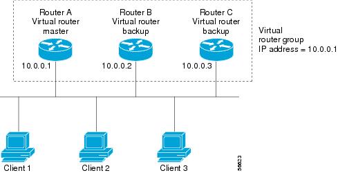
Because the virtual IP address uses the IP address of the physical Ethernet interface of Router A, Router A is the master (also known as the IP address owner). As the master, Router A owns the virtual IP address of the VRRP group and forwards packets sent to this IP address. Clients 1 through 3 are configured with the default gateway IP address of 10.0.0.1.
Routers B and C function as backups. If the master fails, the backup router with the highest priority becomes the master and takes over the virtual IP address to provide uninterrupted service for the LAN hosts. When router A recovers, it becomes the master again. For more information, see the “VRRP Router Priority and Preemption” section.

Note![]() In Cisco NX-OS Release 4.1(2) and later, packets received on a routed port destined for the VRRP virtual IP address terminates on the local router, regardless of whether that router is the master VRRP router or a backup VRRP router. This includes ping and Telnet traffic. Packets received on a Layer 2 (VLAN) interface destined for the VRRP virtual IP address terminates on the master router.
In Cisco NX-OS Release 4.1(2) and later, packets received on a routed port destined for the VRRP virtual IP address terminates on the local router, regardless of whether that router is the master VRRP router or a backup VRRP router. This includes ping and Telnet traffic. Packets received on a Layer 2 (VLAN) interface destined for the VRRP virtual IP address terminates on the master router.
VRRP Benefits
The benefits of VRRP are as follows:
- Redundancy—Enables you to configure multiple routers as the default gateway router, which reduces the possibility of a single point of failure in a network.
- Load sharing—Allows traffic to and from LAN clients to be shared by multiple routers. The traffic load is shared more equitably among available routers.
- Multiple VRRP groups—Supports up to 255 VRRP groups on a router physical interface if the platform supports multiple MAC addresses. Multiple VRRP groups enable you to implement redundancy and load sharing in your LAN topology.
- Multiple IP addresses—Allows you to manage multiple IP addresses, including secondary IP addresses. If you have multiple subnets configured on an Ethernet interface, you can configure VRRP on each subnet.
- Preemption—Enables you to preempt a backup router that has taken over for a failing master with a higher priority backup router that has become available.
- Advertisement protocol—Uses a dedicated Internet Assigned Numbers Authority (IANA) standard multicast address (224.0.0.18) for VRRP advertisements. This addressing scheme minimizes the number of routers that must service the multicasts and allows test equipment to accurately identify VRRP packets on a segment. IANA has assigned the IP protocol number 112 to VRRP.
- VRRP tracking—Ensures that the best VRRP router is the master for the group by altering VRRP priorities based on interface states.
Multiple VRRP Groups
You can configure up to 255 VRRP groups on a physical interface. The number of VRRP groups that a router interface can support depends on the following factors:
In a topology where multiple VRRP groups are configured on a router interface, the interface can act as a master for one VRRP group and as a backup for one or more other VRRP groups.
Figure 20-2 shows a LAN topology in which VRRP is configured so that Routers A and B share the traffic to and from clients 1 through 4. Routers A and B act as backups to each other if either router fails.
Figure 20-2 Load Sharing and Redundancy VRRP Topology

This topology contains two virtual IP addresses for two VRRP groups that overlap. For VRRP group 1, Router A is the owner of IP address 10.0.0.1 and is the master. Router B is the backup to Router A. Clients 1 and 2 are configured with the default gateway IP address of 10.0.0.1.
For VRRP group 2, Router B is the owner of IP address 10.0.0.2 and is the master. Router A is the backup to router B. Clients 3 and 4 are configured with the default gateway IP address of 10.0.0.2.
VRRP Router Priority and Preemption
An important aspect of the VRRP redundancy scheme is the VRRP router priority because the priority determines the role that each VRRP router plays and what happens if the master router fails.
If a VRRP router owns the virtual IP address and the IP address of the physical interface, this router functions as the master. The priority of the master is 255.
Priority also determines if a VRRP router functions as a backup router and the order of ascendancy to becoming a master if the master fails.
For example, if Router A, the master in a LAN topology, fails, VRRP must determine if backups B or C should take over. If you configure Router B with priority 101 and Router C with the default priority of 100, VRRP selects Router B to become the master because it has the higher priority. If you configure routers B and C with the default priority of 100, VRRP selects the backup with the higher IP address to become the master.
VRRP uses preemption to determine what happens after a VRRP backup router becomes the master. With preemption enabled by default, VRRP switches to a backup if that backup comes online with a priority higher than the new master. For example, if Router A is the master and fails, VRRP selects Router B (next in order of priority). If Router C comes online with a higher priority than Router B, VRRP selects Router C as the new master, even though Router B has not failed.
If you disable preemption, VRRP switches only if the original master recovers or the new master fails.
vPC and VRRP
VRRP interoperates with virtual port channels (vPCs). vPCs allow links that are physically connected to two different Cisco Nexus 7000 series devices to appear as a single port channel by a third device. See the Cisco Nexus 7000 Series NX-OS Layer 2 Switching Configuration Guide, Release 5.x, for more information on vPCs.
vPC forwards traffic through both the master VRRP router as well as the backup VRRP router. See the “Configuring VRRP Priority” section.
Note![]() You should configure VRRP on the primary vPC peer device as active and VRRP on the vPC secondary device as standby.
You should configure VRRP on the primary vPC peer device as active and VRRP on the vPC secondary device as standby.
VRRP Advertisements
The VRRP master sends VRRP advertisements to other VRRP routers in the same group. The advertisements communicate the priority and state of the master. Cisco NX-OS encapsulates the VRRP advertisements in IP packets and sends them to the IP multicast address assigned to the VRRP group. Cisco NX-OS sends the advertisements once every second by default, but you can configure a different advertisement interval.
VRRP Authentication
VRRP Tracking
VRRP supports the following two options for tracking:
- Native interface tracking— Tracks the state of an interface and uses that state to determine the priority of the VRRP router in a VRRP group. The tracked state is down if the interface is down or if the interface does not have a primary IP address.
- Object tracking—Tracks the state of a configured object and uses that state to determine the priority of the VRRP router in a VRRP group. See Chapter 21, “Configuring Object Tracking” for more information on object tracking.
If the tracked state (interface or object) goes down, VRRP updates the priority based on what you configure the new priority to be for the tracked state. When the tracked state comes up, VRRP restores the original priority for the virtual router group.
For example, you may want to lower the priority of a VRRP group member if its uplink to the network goes down so another group member can take over as master for the VRRP group. See the “Configuring VRRP Interface State Tracking” section for more information.
Note![]() VRRP does not support Layer 2 interface tracking.
VRRP does not support Layer 2 interface tracking.
BFD
This feature supports bidirectional forwarding detection (BFD). BFD is a detection protocol that provides fast-forwarding and path-failure detection times. BFD provides subsecond failure detection between two adjacent devices and can be less CPU-intensive than protocol hello messages because some of the BFD load can be distributed onto the data plane on supported modules. See the Cisco Nexus 7000 Series NX-OS Interfaces Configuration Guide, Release 5.x, for more information.
High Availability
VRRP supports high availability through stateful restarts and stateful switchovers. A stateful restart occurs when the VRRP process fails and is restarted. Stateful switchover occurs when the active supervisor switches to the standby supervisor. Cisco NX-OS applies the run-time configuration after the switchover.
Virtualization Support
VRRP supports virtual routing and forwarding (VRF) instances. VRF exists within virtual device contexts (VDCs). By default, Cisco NX-OS places you in the default VDC and default VRF unless you specifically configure another VDC and VRF.
If you change the VRF membership of an interface, Cisco NX-OS removes all Layer 3 configurations, including VRRP.
For more information, see the Cisco Nexus 7000 Series NX-OS Virtual Device Context Configuration Guide, Release 5.x, and see Chapter14, “Configuring Layer 3 Virtualization”
Licensing Requirements for VRRP
The following table shows the licensing requirements for this feature:
Guidelines and Limitations for VRRP
VRRP has the following configuration guidelines and limitations:
- You cannot configure VRRP on the management interface.
- When VRRP is enabled, you should replicate the VRRP configuration across devices in your network.
- We recommend that you do not configure more than one first-hop redundancy protocol on the same interface.
- You must configure an IP address for the interface that you configure VRRP on and enable that interface before VRRP becomes active.
- Cisco NX-OS removes all Layer 3 configurations on an interface when you change the interface VRF membership, port channel membership, or when you change the port mode to Layer 2.
- When you configure VRRP to track a Layer 2 interface, you must shut down the Layer 2 interface and reenable the interface to update the VRRP priority to reflect the state of the Layer 2 interface
- BFD for VRRP can only be configured between two routers..
Default Settings
Table 20-1 lists the default settings for VRRP parameters.
|
|
|
|---|---|
Configuring VRRP
This section includes the following topics:
- Enabling the VRRP Feature
- Configuring VRRP Groups
- Configuring VRRP Priority
- Configuring VRRP Authentication
- Configuring Time Intervals for Advertisement Packets
- Disabling Preemption
- Configuring VRRP Interface State Tracking
Note![]() If you are familiar with the Cisco IOS CLI, be aware that the Cisco NX-OS commands for this feature might differ from the Cisco IOS commands that you would use.
If you are familiar with the Cisco IOS CLI, be aware that the Cisco NX-OS commands for this feature might differ from the Cisco IOS commands that you would use.
Enabling the VRRP Feature
You must globally enable the VRRP feature before you can configure and enable any VRRP groups.
To enable the VRRP feature, use the following command in global configuration mode:
|
|
|
|---|---|
To disable the VRRP feature in a VDC and remove all associated configurations, use the following command in global configuration mode:
|
|
|
|---|---|
Configuring VRRP Groups
You can create a VRRP group, assign the virtual IP address, and enable the group.
You can configure one virtual IPv4 address for a VRRP group. By default, the master VRRP router drops the packets addressed directly to the virtual IP address because the VRRP master is only intended as a next-hop router to forward packets. Some applications require that Cisco NX-OS accept packets addressed to the virtual router IP. Use the secondary option to the virtual IP address to accept these packets when the local router is the VRRP master.
Once you have configured the VRRP group, you must explicitly enable the group before it becomes active.
BEFORE YOU BEGIN
Ensure that you are in the correct VDC (or use the switchto vdc command).
Ensure that you configure an IP address on the interface (see the “Configuring IPv4 Addressing” section).
SUMMARY STEPS
2.![]() interface interface-type slot/port
interface interface-type slot/port
DETAILED STEPS
Configuring VRRP Priority
The valid priority range for a virtual router is from 1 to 254 (1 is the lowest priority and 254 is the highest). The default priority value for backups is 100. For devices whose interface IP address is the same as the primary virtual IP address (the master), the default value is 255.
If you configure VRRP on a vPC-enabled interface, you can optionally configure the upper and lower threshold values to control when to fail over to the vPC trunk. If the backup router priority falls below the lower threshold, VRRP sends all backup router traffic across the vPC trunk to forward through the master VRRP router. VRRP maintains this scenario until the backup VRRP router priority increases above the upper threshold.
BEFORE YOU BEGIN
You must enable VRRP (see the “Configuring VRRP” section).
Ensure that you have configured an IP address on the interface (see the “Configuring IPv4 Addressing” section).
Ensure that you are in the correct VDC (or use the switchto vdc command).
SUMMARY STEPS
2.![]() interface interface-type slot/port
interface interface-type slot/port
5.![]() priority leve l [ forwarding-threshold lower lower-value upper upper-value ]
priority leve l [ forwarding-threshold lower lower-value upper upper-value ]
DETAILED STEPS
Configuring VRRP Authentication
You can configure simple text authentication for a VRRP group.
BEFORE YOU BEGIN
Ensure that the authentication configuration is identical for all VRRP devices in the network.
Ensure that you have enabled VRRP (see the “Configuring VRRP” section).
Ensure that you have configured an IP address on the interface (see the “Configuring IPv4 Addressing” section).
Ensure that you are in the correct VDC (or use the switchto vdc command).
SUMMARY STEPS
2.![]() interface interface-type slot/port
interface interface-type slot/port
DETAILED STEPS
Configuring Time Intervals for Advertisement Packets
You can configure the time intervals for advertisement packets.
BEFORE YOU BEGIN
You must enable VRRP (see the “Configuring VRRP” section).
Ensure that you have configured an IP address on the interface (see the “Configuring IPv4 Addressing” section).
Ensure that you are in the correct VDC (or use the switchto vdc command).
SUMMARY STEPS
2.![]() interface interface-type slot/port
interface interface-type slot/port
DETAILED STEPS
|
|
|
|
|---|---|---|
interface interface-type slot/port |
||
Sets the interval time in seconds between sending advertisement frames. The range is from 1 to 255. The default is 1 second. |
||
Disabling Preemption
You can disable preemption for a VRRP group member. If you disable preemption, a higher-priority backup router does not take over for a lower-priority master router. Preemption is enabled by default.
BEFORE YOU BEGIN
You must enable VRRP (see the “Configuring VRRP” section).
Ensure that you have configured an IP address on the interface (see the “Configuring IPv4 Addressing” section).
Ensure that you are in the correct VDC (or use the switchto vdc command).
SUMMARY STEPS
DETAILED STEPS
|
|
|
|
|---|---|---|
interface interface-type slot/port |
||
Disables the preempt option and allows the master to remain when a higher-priority backup appears. |
||
Configuring VRRP Interface State Tracking
Interface state tracking changes the priority of the virtual router based on the state of another interface in the device. When the tracked interface goes down or the IP address is removed, Cisco NX-OS assigns the tracking priority value to the virtual router. When the tracked interface comes up and an IP address is configured on this interface, Cisco NX-OS restores the configured priority to the virtual router (see the“Configuring VRRP Priority” section).
Note![]() For interface state tracking to function, you must enable preemption on the interface.
For interface state tracking to function, you must enable preemption on the interface.
Note![]() VRRP does not support Layer 2 interface tracking.
VRRP does not support Layer 2 interface tracking.
BEFORE YOU BEGIN
You must enable VRRP (see the “Configuring VRRP” section).
Ensure that you have configured an IP address on the interface (see the “Configuring IPv4 Addressing” section).
Ensure that you have enabled the virtual router (see the “Configuring VRRP Groups” section).
Ensure that you are in the correct VDC (or use the switchto vdc command).
SUMMARY STEPS
2.![]() interface interface-type slot/port
interface interface-type slot/port
DETAILED STEPS
Verifying the VRRP Configuration
To display VRRP configuration information, perform one of the following tasks:
|
|
|
|---|---|
Monitoring VRRP Statistics
To display VRRP statistics, use the following commands:
|
|
|
|---|---|
Use the clear vrrp statistics command to clear all the VRRP statistics for all interfaces in the device.
Use the clear vrrp vr command to clear the IPv4 VRRP statistics for a specified interface.
Use the clear vrrp ipv4 command to clear all the statistics for the specified IPv4 virtual router.
Configuration Examples for VRRP
In this example, Router A and Router B each belong to three VRRP groups. In the configuration, each group has the following properties:
–![]() Virtual IP address is 10.1.0.10.
Virtual IP address is 10.1.0.10.
–![]() Router A will become the master for this group with priority 120.
Router A will become the master for this group with priority 120.
–![]() Advertising interval is 3 seconds.
Advertising interval is 3 seconds.
–![]() Router B will become the master for this group with priority 200.
Router B will become the master for this group with priority 200.
–![]() Advertising interval is 30 seconds.
Advertising interval is 30 seconds.
–![]() Router A will become the master for this group first because it has a higher IP address (10.1.0.2).
Router A will become the master for this group first because it has a higher IP address (10.1.0.2).
–![]() Advertising interval is the default 1 second.
Advertising interval is the default 1 second.
Additional References
For additional information related to implementing VRRP, see the following sections:
Related Documents
|
|
|
|---|---|
Cisco Nexus 7000 Series NX-OS Unicast Routing Command Reference, Release 5.x |
|
Cisco Nexus 7000 Series NX-OS High Availability and Redundancy Guide, Release 5.x |
Feature History for VRRP
Table 20-2 lists the release history for this feature.
|
|
|
|
|---|---|---|
 Feedback