- New and Changed Information
- Index
- Preface
- Overview
- Configuring AAA
- Configuring RADIUS
- Configuring TACACS+
- Configuring User Accounts and RBAC
- Configuring 802.1X
- Configuring IP ACLs
- Configuring MAC ACLs
- Configuring VLAN ACLs
- Configuring Port Security
- Configuring DHCP Snooping
- Configuring Dynamic ARP Inspection
- Configuring Source Guard
- Configuring Keychain Management
- Configuring Traffic Storm Control
Configuring Dynamic ARP Inspection
This chapter describes how to configure dynamic Address Resolution Protocol (ARP) inspection (DAI) on an NX-OS device.
This chapter includes the following sections:
•![]() Licensing Requirements for DAI
Licensing Requirements for DAI
•![]() Displaying and Clearing DAI Statistics
Displaying and Clearing DAI Statistics
•![]() Field Descriptions for ARP ACLs
Field Descriptions for ARP ACLs
Information About DAI
This section includes the following topics:
•![]() Understanding ARP Spoofing Attacks
Understanding ARP Spoofing Attacks
•![]() Understanding DAI and ARP Spoofing Attacks
Understanding DAI and ARP Spoofing Attacks
•![]() Interface Trust States and Network Security
Interface Trust States and Network Security
•![]() Prioritizing ARP ACLs and DHCP Snooping Entries
Prioritizing ARP ACLs and DHCP Snooping Entries
Understanding ARP
ARP provides IP communication within a Layer 2 broadcast domain by mapping an IP address to a MAC address. For example, host B wants to send information to host A but does not have the MAC address of host A in its ARP cache. In ARP terms, host B is the sender and host A is the target.
To get the MAC address of host A, host B generates a broadcast message for all hosts within the broadcast domain to obtain the MAC address associated with the IP address of host A. All hosts within the broadcast domain receive the ARP request, and host A responds with its MAC address.
Understanding ARP Spoofing Attacks
ARP spoofing attacks and ARP cache poisoning can occur because ARP allows a reply from a host even if an ARP request was not received. After the attack, all traffic from the device under attack flows through the attacker's computer and then to the router, switch, or host.
An ARP spoofing attack can affect hosts, switches, and routers connected to your Layer 2 network by sending false information to the ARP caches of the devices connected to the subnet. Sending false information to an ARP cache is known as ARP cache poisoning. Spoof attacks can also intercept traffic intended for other hosts on the subnet. Figure 12-1 shows an example of ARP cache poisoning.
Figure 12-1 ARP Cache Poisoning
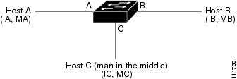
Hosts A, B, and C are connected to the device on interfaces A, B, and C, all of which are on the same subnet. Their IP and MAC addresses are shown in parentheses; for example, host A uses IP address IA and MAC address MA. When host A needs to send IP data to host B, it broadcasts an ARP request for the MAC address associated with IP address IB. When the device and host B receive the ARP request, they populate their ARP caches with an ARP binding for a host with the IP address IA and a MAC address MA; for example, IP address IA is bound to MAC address MA. When host B responds, the device and host A populate their ARP caches with a binding for a host with the IP address IB and the MAC address MB.
Host C can poison the ARP caches of the device, host A, and host B by broadcasting two forged ARP responses with bindings: one for a host with an IP address of IA and a MAC address of MC and another for a host with the IP address of IB and a MAC address of MC. Host B and the device then use the MAC address MC as the destination MAC address for traffic intended for IA, which means that host C intercepts that traffic. Likewise, host A and the device use the MAC address MC as the destination MAC address for traffic intended for IB.
Because host C knows the true MAC addresses associated with IA and IB, it can forward the intercepted traffic to those hosts by using the correct MAC address as the destination. This topology, in which host C has inserted itself into the traffic stream from host A to host B, is an example of a man-in-the middle attack.
Understanding DAI and ARP Spoofing Attacks
DAI ensures that only valid ARP requests and responses are relayed. When DAI is enabled and properly configured, an NX-OS device performs these activities:
•![]() Intercepts all ARP requests and responses on untrusted ports
Intercepts all ARP requests and responses on untrusted ports
•![]() Verifies that each of these intercepted packets has a valid IP-to-MAC address binding before updating the local ARP cache or before forwarding the packet to the appropriate destination
Verifies that each of these intercepted packets has a valid IP-to-MAC address binding before updating the local ARP cache or before forwarding the packet to the appropriate destination
•![]() Drops invalid ARP packets
Drops invalid ARP packets
DAI can determine the validity of an ARP packet based on valid IP-to-MAC address bindings stored in a Dynamic Host Configuration Protocol (DHCP) snooping binding database. This database is built by DHCP snooping if DHCP snooping is enabled on the VLANs and on the device. It can also contain static entries that you create. If the ARP packet is received on a trusted interface, the device forwards the packet without any checks. On untrusted interfaces, the device forwards the packet only if it is valid.
DAI can validate ARP packets against user-configured ARP access control lists (ACLs) for hosts with statically configured IP addresses (see the "Applying ARP ACLs to VLANs for DAI Filtering" section). The device logs dropped packets (see the "Logging DAI Packets" section).
You can configure DAI to drop ARP packets when the IP addresses in the packets are invalid or when the MAC addresses in the body of the ARP packets do not match the addresses specified in the Ethernet header (see the "Enabling or Disabling Additional Validation" section).
Interface Trust States and Network Security
DAI associates a trust state with each interface on the device. Packets that arrive on trusted interfaces bypass all DAI validation checks, and packets that arrive on untrusted interfaces go through the DAI validation process.
In a typical network configuration, the guidelines for configuring the trust state of interfaces as follows:
•![]() Untrusted—Interfaces that are connected to hosts
Untrusted—Interfaces that are connected to hosts
•![]() Trusted—Interfaces that are connected to devices
Trusted—Interfaces that are connected to devices
With this configuration, all ARP packets that enter the network from a device bypass the security check. No other validation is needed at any other place in the VLAN or in the network. For information about configuring the trust state of an interface, see the "Configuring the DAI Trust State of a Layer 2 Interface" section.

In Figure 12-2, assume that both device A and device B are running DAI on the VLAN that includes host 1 and host 2. If host 1 and host 2 acquire their IP addresses from the DHCP server connected to device A, only device A binds the IP-to-MAC address of host 1. If the interface between device A and device B is untrusted, the ARP packets from host 1 are dropped by device B and connectivity between host 1 and host 2 is lost.
Figure 12-2 ARP Packet Validation on a VLAN Enabled for DAI
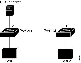
If you configure interfaces as trusted when they should be untrusted, you may open a security hole in a network. If device A is not running DAI, host 1 can easily poison the ARP cache of device B (and host 2, if you configured the link between the devices as trusted). This condition can occur even though device B is running DAI.
DAI ensures that hosts (on untrusted interfaces) connected to a device that runs DAI do not poison the ARP caches of other hosts in the network; however, DAI does not prevent hosts in other portions of the network from poisoning the caches of the hosts that are connected to a device that runs DAI.
If some devices in a VLAN run DAI and other devices do not, then the guidelines for configuring the trust state of interfaces on a device running DAI becomes the following:
•![]() Untrusted—Interfaces that are connected to hosts or to devices that are not running DAI
Untrusted—Interfaces that are connected to hosts or to devices that are not running DAI
•![]() Trusted—Interfaces that are connected to devices that are running DAI
Trusted—Interfaces that are connected to devices that are running DAI
To validate the bindings of packets from devices that are not running DAI, configure ARP ACLs on the device running DAI. When you cannot determine the bindings, isolate at Layer 3 the devices that run DAI from devices that do not run DAI.

Note ![]() Depending on your network setup, you may not be able to validate a given ARP packet on all devices in the VLAN.
Depending on your network setup, you may not be able to validate a given ARP packet on all devices in the VLAN.
Prioritizing ARP ACLs and DHCP Snooping Entries
By default, DAI filters DAI traffic by comparing DAI packets to IP-MAC address bindings in the DHCP snooping database.
When you apply an ARP ACL to traffic, the ARP ACLs take precedence over the default filtering behavior.The device first compares ARP packets to user-configured ARP ACLs. If the ARP ACL denies the ARP packet, the device denies the packet regardless of whether a valid IP-MAC binding exists in the DHCP snooping database.
Note ![]() VLAN ACLs (VACLs) take precedence over both ARP ACLs and DHCP snooping entries. For example, if you apply a VACL and an ARP ACL to a VLAN and you configured the VACL to act on ARP traffic, the device permits or denies ARP traffic as determined by the VACL, not the ARP ACL or DHCP snooping entries.
VLAN ACLs (VACLs) take precedence over both ARP ACLs and DHCP snooping entries. For example, if you apply a VACL and an ARP ACL to a VLAN and you configured the VACL to act on ARP traffic, the device permits or denies ARP traffic as determined by the VACL, not the ARP ACL or DHCP snooping entries.
For information about configuring ARP ACLs, see the "Configuring ARP ACLs" section. For information about applying an ARP ACL, see the "Applying ARP ACLs to VLANs for DAI Filtering" section.
Logging DAI Packets
NX-OS maintains a buffer of log entries about DAI packets processed. Each log entry contains flow information, such as the receiving VLAN, the port number, the source and destination IP addresses, and the source and destination MAC addresses.
You can also specify the type of packets that are logged. By default, an NX-OS device logs only packets that DAI drops. For configuration information, see the "Configuring DAI Log Filtering" section.
If the log buffer overflows, the device overwrites the oldest DAI log entries with newer entries. You can configure the maximum number of entries in the buffer. For more information, see the "Configuring the DAI Logging Buffer Size" section.
Note ![]() NX-OS does not generate system messages about DAI packets that are logged.
NX-OS does not generate system messages about DAI packets that are logged.
Virtualization Support
The following information applies to DAI used in Virtual Device Contexts (VDCs):
•![]() IP-MAC address bindings are unique per VDC.
IP-MAC address bindings are unique per VDC.
•![]() ARP ACLs are unique per VDC. You cannot use an ACL that you created in one VDC in a different VDC.
ARP ACLs are unique per VDC. You cannot use an ACL that you created in one VDC in a different VDC.
•![]() Because ACLs are not shared by VDCs, you can reuse ACL names in different VDCs.
Because ACLs are not shared by VDCs, you can reuse ACL names in different VDCs.
•![]() The system does not limit ARP ACLs or rules on a per-VDC basis.
The system does not limit ARP ACLs or rules on a per-VDC basis.
Licensing Requirements for DAI
The following table shows the licensing requirements for this feature:
Prerequisites for DAI
You should be familiar with the following before you configure DAI:
•![]() ARP
ARP
•![]() DHCP snooping
DHCP snooping
Guidelines and Limitations
DAI has the following configuration guidelines and limitations:
•![]() DAI is an ingress security feature; it does not perform any egress checking.
DAI is an ingress security feature; it does not perform any egress checking.
•![]() DAI is not effective for hosts connected to devices that do not support DAI or that do not have this feature enabled. Because man-in-the-middle attacks are limited to a single Layer 2 broadcast domain, you should separate the domain with DAI from domains without DAI. This separation secures the ARP caches of hosts in the domain with DAI.
DAI is not effective for hosts connected to devices that do not support DAI or that do not have this feature enabled. Because man-in-the-middle attacks are limited to a single Layer 2 broadcast domain, you should separate the domain with DAI from domains without DAI. This separation secures the ARP caches of hosts in the domain with DAI.
•![]() DAI depends on the entries in the DHCP snooping binding database to verify IP-to-MAC address bindings in incoming ARP requests and ARP responses. If you want DAI to use static IP-MAC address bindings to determine if ARP packets are valid, DHCP snooping needs only to be enabled. If you want DAI to use dynamic IP-MAC address bindings to determine if ARP packets are valid, DHCP snooping must configured on the same VLANs on which you configure DAI. For configuration information, see the "Configuring DHCP Snooping" section on page 11-7.
DAI depends on the entries in the DHCP snooping binding database to verify IP-to-MAC address bindings in incoming ARP requests and ARP responses. If you want DAI to use static IP-MAC address bindings to determine if ARP packets are valid, DHCP snooping needs only to be enabled. If you want DAI to use dynamic IP-MAC address bindings to determine if ARP packets are valid, DHCP snooping must configured on the same VLANs on which you configure DAI. For configuration information, see the "Configuring DHCP Snooping" section on page 11-7.
•![]() When you use the feature dhcp command to enable the DHCP snooping feature, there is a delay of approximately 30 seconds before the I/O modules receive DHCP snooping or DAI configuration. This delay occurs regardless of the method that you use to change from a configuration with DHCP snooping disabled to a configuration with DHCP snooping enabled. For example, if you use the Rollback feature to revert to a configuration that enables DHCP snooping, the I/O modules receive DHCP snooping and DAI configuration approximately 30 seconds after you complete the rollback.
When you use the feature dhcp command to enable the DHCP snooping feature, there is a delay of approximately 30 seconds before the I/O modules receive DHCP snooping or DAI configuration. This delay occurs regardless of the method that you use to change from a configuration with DHCP snooping disabled to a configuration with DHCP snooping enabled. For example, if you use the Rollback feature to revert to a configuration that enables DHCP snooping, the I/O modules receive DHCP snooping and DAI configuration approximately 30 seconds after you complete the rollback.
•![]() When DHCP snooping is disabled or used in a non-DHCP environment, you should use ARP ACLs to permit or to deny packets.
When DHCP snooping is disabled or used in a non-DHCP environment, you should use ARP ACLs to permit or to deny packets.
•![]() DAI is supported on access ports, trunk ports, port-channel ports, and private VLAN ports.
DAI is supported on access ports, trunk ports, port-channel ports, and private VLAN ports.
•![]() The DAI trust configuration of a port channel determines the trust state of all physical ports that you assign to the port channel. For example, if you have configured a physical port as a trusted interface and then you add that physical port to a port channel that is an untrusted interface, the physical port becomes untrusted.
The DAI trust configuration of a port channel determines the trust state of all physical ports that you assign to the port channel. For example, if you have configured a physical port as a trusted interface and then you add that physical port to a port channel that is an untrusted interface, the physical port becomes untrusted.
•![]() When you remove a physical port from a port channel, the physical port does not retain the DAI trust state configuration of the port channel.
When you remove a physical port from a port channel, the physical port does not retain the DAI trust state configuration of the port channel.
•![]() When you change the trust state on the port channel, the device configures a new trust state on all the physical ports that comprise the channel.
When you change the trust state on the port channel, the device configures a new trust state on all the physical ports that comprise the channel.
•![]() If you want DAI to use static IP-MAC address bindings to determine if ARP packets are valid, ensure that the DHCP snooping feature is enabled and that you have configured the static IP-MAC address bindings. For configuration information, see the "Configuring DHCP Snooping" section on page 11-7.
If you want DAI to use static IP-MAC address bindings to determine if ARP packets are valid, ensure that the DHCP snooping feature is enabled and that you have configured the static IP-MAC address bindings. For configuration information, see the "Configuring DHCP Snooping" section on page 11-7.
•![]() If you want DAI to use dynamic IP-MAC address bindings to determine if ARP packets are valid, ensure that DHCP snooping is configured (see the "Configuring DHCP Snooping" section on page 11-7).
If you want DAI to use dynamic IP-MAC address bindings to determine if ARP packets are valid, ensure that DHCP snooping is configured (see the "Configuring DHCP Snooping" section on page 11-7).
•![]() For each device that you use DCNM to configure DAI, ensure that you configure the logging level for DHCP snooping to 6 (Informational) or a higher level. To configure the device with the minimal required logging configuration, log into the command-line interface of the device and use the following commands:
For each device that you use DCNM to configure DAI, ensure that you configure the logging level for DHCP snooping to 6 (Informational) or a higher level. To configure the device with the minimal required logging configuration, log into the command-line interface of the device and use the following commands:
switch(config)# logging level dhcp 6
switch(config)# logging logfile messages 6
switch(config)# logging event link-status default
For more information about NX-OS system-message logging requirements, see the Cisco DCNM Fundamentals Configuration Guide, Release 4.1.
Configuring DAI
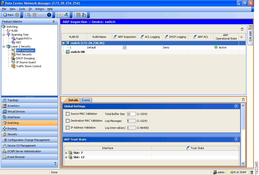
Figure 12-3 shows the ARP Inspection content pane.
Figure 12-3 ARP Inspection Pane
This section includes the following topics:
•![]() Enabling or Disabling DAI on VLANs
Enabling or Disabling DAI on VLANs
•![]() Configuring the DAI Trust State of a Layer 2 Interface
Configuring the DAI Trust State of a Layer 2 Interface
•![]() Applying ARP ACLs to VLANs for DAI Filtering
Applying ARP ACLs to VLANs for DAI Filtering
•![]() Enabling or Disabling Additional Validation
Enabling or Disabling Additional Validation
•![]() Configuring the DAI Logging Buffer Size
Configuring the DAI Logging Buffer Size
•![]() Configuring the DAI System Logging Rate
Configuring the DAI System Logging Rate
•![]() Configuring DAI Log Filtering
Configuring DAI Log Filtering
Enabling or Disabling DAI on VLANs
You can enable or disable DAI on VLANs.
BEFORE YOU BEGIN
By default, DAI is disabled on all VLANs.
If you are enabling DAI, ensure the following:
•![]() DHCP snooping is enabled. For more information, see the "Enabling or Disabling the DHCP Snooping Feature" section on page 11-8.
DHCP snooping is enabled. For more information, see the "Enabling or Disabling the DHCP Snooping Feature" section on page 11-8.
•![]() The VLANs on which you want to enable DAI are configured.
The VLANs on which you want to enable DAI are configured.
•![]() Ensure that you configure the logging level for DHCP snooping to 6 (Informational) or a higher level on the device. To configure the device with the minimal required logging configuration, log into the command-line interface of the device and use the following commands:
Ensure that you configure the logging level for DHCP snooping to 6 (Informational) or a higher level on the device. To configure the device with the minimal required logging configuration, log into the command-line interface of the device and use the following commands:
switch(config)# logging level dhcp 6
switch(config)# logging logfile messages 6
switch(config)# logging event link-status default
For more information about NX-OS system-message logging requirements, see the Cisco DCNM Fundamentals Configuration Guide, Release 4.1.
DETAILED STEPS
To enable or disable DAI on a VLAN, follow these steps:
Step 1 ![]() From the Feature Selector pane, choose Switching > Layer 2 Security > ARP Inspection.
From the Feature Selector pane, choose Switching > Layer 2 Security > ARP Inspection.
The available devices appear in the Summary pane.
Step 2 ![]() From the Summary pane, double-click the device that has the VLAN that you want to configure with DAI.
From the Summary pane, double-click the device that has the VLAN that you want to configure with DAI.
The VLANs on the device appear in the Summary pane.
Step 3 ![]() From the Summary pane, click the VLAN that you want to configure with DAI.
From the Summary pane, click the VLAN that you want to configure with DAI.
The DAI VLAN Details tab appears in the Details pane.
Step 4 ![]() From the DAI VLAN Details tab, do one of the following:
From the DAI VLAN Details tab, do one of the following:
•![]() To enable DAI on the selected VLAN, check ARP Inspection.
To enable DAI on the selected VLAN, check ARP Inspection.
•![]() To disable DAI on the selected VLAN, uncheck ARP Inspection.
To disable DAI on the selected VLAN, uncheck ARP Inspection.
Step 5 ![]() From the menu bar, choose File > Deploy to apply your changes to the device.
From the menu bar, choose File > Deploy to apply your changes to the device.
Configuring the DAI Trust State of a Layer 2 Interface
You can configure the DAI interface trust state of a Layer 2 interface.
A device forwards ARP packets that it receives on a trusted Layer 2 interface but does not check them. For more information about DAI trust states, see the "Interface Trust States and Network Security" section.
On untrusted interfaces, the device intercepts all ARP requests and responses, verifies that the intercepted packets have valid IP-MAC address bindings before updating the local cache and forwarding the packet to the appropriate destination. If the device determines that packets have invalid bindings, it drops the packets and logs them according to the logging configuration. For more information, see the "Configuring DAI Log Filtering" section.
BEFORE YOU BEGIN
By default, all interfaces are untrusted.
If you are enabling DAI, ensure that DHCP snooping is enabled. For more information, see the "Enabling or Disabling the DHCP Snooping Feature" section on page 11-8.
DETAILED STEPS
To configure the DAI trust state of a Layer 2 interface, follow these steps:
Step 1 ![]() From the Feature Selector pane, choose Switching > Layer 2 Security > ARP Inspection.
From the Feature Selector pane, choose Switching > Layer 2 Security > ARP Inspection.
The available devices appear in the Summary pane.
Step 2 ![]() From the Summary pane, click the device that has the Layer 2 interface whose DAI trust state you want to configure.
From the Summary pane, click the device that has the Layer 2 interface whose DAI trust state you want to configure.
The Details tab appears in the Details pane.
Step 3 ![]() From the Details tab, expand the ARP Trust State section, if necessary.
From the Details tab, expand the ARP Trust State section, if necessary.
A table of slots on the selected device appears in the ARP Trust State section.
Step 4 ![]() Double-click the slot that contains the Layer 2 interface that you want to configure.
Double-click the slot that contains the Layer 2 interface that you want to configure.
The Layer 2 interfaces on the slot appear. For each interface, a check box in the Trust State column indicates whether the device trusts the interface.
Step 5 ![]() In the Trust State column for the interface that you want to configure, do one of the following:
In the Trust State column for the interface that you want to configure, do one of the following:
•![]() To make the interface a trusted DAI interface, check or uncheck Trust State.
To make the interface a trusted DAI interface, check or uncheck Trust State.
•![]() To make the interface an untrusted DAI interface, uncheck Trust State.
To make the interface an untrusted DAI interface, uncheck Trust State.
Step 6 ![]() From the menu bar, choose File > Deploy to apply your changes to the device.
From the menu bar, choose File > Deploy to apply your changes to the device.
Applying ARP ACLs to VLANs for DAI Filtering
You can apply an ARP ACL to one or more VLANs. The device permits packets only if the ACL permits them.
BEFORE YOU BEGIN
By default, no VLANs have an ARP ACL applied.
Ensure that the ARP ACL that you want to apply is correctly configured. For information about configuring an ARP ACL, see the "Configuring ARP ACLs" section.
DETAILED STEPS
To apply an ARP ACL to a VLAN for DAI filtering, follow these steps:
Step 1 ![]() From the Feature Selector pane, choose Switching > Layer 2 Security > ARP Inspection.
From the Feature Selector pane, choose Switching > Layer 2 Security > ARP Inspection.
The available devices appear in the Summary pane.
Step 2 ![]() From the Summary pane, double-click the device that has the VLAN that you want to configure with an ARP ACL.
From the Summary pane, double-click the device that has the VLAN that you want to configure with an ARP ACL.
The VLANs on the device appear in the Summary pane.
Step 3 ![]() From the Summary pane, click the VLAN that you want to configure with an ARP ACL.
From the Summary pane, click the VLAN that you want to configure with an ARP ACL.
The DAI VLAN Details tab appears in the Details pane. On the DAI VLAN Details tab, the ARP ACL drop-down list appears.
Step 4 ![]() From the DAI VLAN Details tab, do one of the following:
From the DAI VLAN Details tab, do one of the following:
•![]() To apply an ARP ACL to the VLAN, from the ARP ACL drop-down list, choose the ACL that you want to apply.
To apply an ARP ACL to the VLAN, from the ARP ACL drop-down list, choose the ACL that you want to apply.
•![]() To remove an ARP ACL from the VLAN, from the menu bar, choose Actions > Remove ARP ACL from VLAN.
To remove an ARP ACL from the VLAN, from the menu bar, choose Actions > Remove ARP ACL from VLAN.
Step 5 ![]() From the menu bar, choose File > Deploy to apply your changes to the device.
From the menu bar, choose File > Deploy to apply your changes to the device.
Enabling or Disabling Additional Validation
You can enable or disable additional validation of ARP packets.
DAI intercepts, logs, and discards ARP packets with invalid IP-to-MAC address bindings. You can enable additional validation on the destination MAC address, the sender and target IP addresses, and the source MAC address.
BEFORE YOU BEGIN
By default, no additional validation of ARP packets is enabled.
DETAILED STEPS
To enable or disable additional validation, follow these steps:
Step 1 ![]() From the Feature Selector pane, choose Switching > Layer 2 Security > ARP Inspection.
From the Feature Selector pane, choose Switching > Layer 2 Security > ARP Inspection.
The available devices appear in the Summary pane.
Step 2 ![]() From the Summary pane, double-click the device that you want to configure with additional validation.
From the Summary pane, double-click the device that you want to configure with additional validation.
The Details tab appears in the Details pane.
Step 3 ![]() From the Details tab, expand the Global Settings section, if necessary.
From the Details tab, expand the Global Settings section, if necessary.
Step 4 ![]() (Optional) To enable or disable source MAC address validation, check or uncheck Source MAC Validation.
(Optional) To enable or disable source MAC address validation, check or uncheck Source MAC Validation.
Step 5 ![]() (Optional) To enable or disable destination MAC address validation, check or uncheck Destination MAC Validation.
(Optional) To enable or disable destination MAC address validation, check or uncheck Destination MAC Validation.
Step 6 ![]() (Optional) To enable or disable source and target IP address validation, check or uncheck IP Address Validation.
(Optional) To enable or disable source and target IP address validation, check or uncheck IP Address Validation.
Step 7 ![]() From the menu bar, choose File > Deploy to apply your changes to the device.
From the menu bar, choose File > Deploy to apply your changes to the device.
Configuring the DAI Logging Buffer Size
You can configure the DAI logging buffer size.
BEFORE YOU BEGIN
The default buffer size is 32 messages.
DETAILED STEPS
To configuring the DAI logging buffer size, follow these steps:
Step 1 ![]() From the Feature Selector pane, choose Switching > Layer 2 Security > ARP Inspection.
From the Feature Selector pane, choose Switching > Layer 2 Security > ARP Inspection.
The available devices appear in the Summary pane.
Step 2 ![]() From the Summary pane, click the device whose DAI logging buffer size you want to configure.
From the Summary pane, click the device whose DAI logging buffer size you want to configure.
The Details tab appears in the Details pane.
Step 3 ![]() From the Details tab, expand the Global Settings section, if necessary.
From the Details tab, expand the Global Settings section, if necessary.
The Total Buffer Size field appears in the Global Settings section.
Step 4 ![]() Click the Total Buffer Size field and enter the maximum number of DAI messages that the buffer can have.
Click the Total Buffer Size field and enter the maximum number of DAI messages that the buffer can have.
Step 5 ![]() From the menu bar, choose File > Deploy to apply your changes to the device.
From the menu bar, choose File > Deploy to apply your changes to the device.
Configuring the DAI System Logging Rate
Note ![]() The DAI system logging rate is not configurable in NX-OS 4.1.
The DAI system logging rate is not configurable in NX-OS 4.1.
You can configure the DAI system logging rate.
BEFORE YOU BEGIN
The default DAI system logging rate is five messages every second.
DETAILED STEPS
To configure the DAI system logging rate, follow these steps:
Step 1 ![]() From the Feature Selector pane, choose Switching > Layer 2 Security > ARP Inspection.
From the Feature Selector pane, choose Switching > Layer 2 Security > ARP Inspection.
The available devices appear in the Summary pane.
Step 2 ![]() From the Summary pane, click the device whose DAI logging buffer size you want to configure.
From the Summary pane, click the device whose DAI logging buffer size you want to configure.
The Details tab appears in the Details pane.
Step 3 ![]() From the Details tab, expand the Global Settings section, if necessary.
From the Details tab, expand the Global Settings section, if necessary.
The Log Messages field and the Log Interval (sec) field appear in the Global Settings section. The device sends messages at the rate of the number of messages in the Log Messages field per the number of seconds in the Log Interval (sec) field.
Step 4 ![]() (Optional) Click the Log Messages field and enter the number of messages.
(Optional) Click the Log Messages field and enter the number of messages.
Step 5 ![]() (Optional) Click the Log Interval(sec) field and enter the number of seconds.
(Optional) Click the Log Interval(sec) field and enter the number of seconds.
Step 6 ![]() From the menu bar, choose File > Deploy to apply your changes to the device.
From the menu bar, choose File > Deploy to apply your changes to the device.
Configuring DAI Log Filtering
You can configure how the device determines whether to log a DAI packet.
BEFORE YOU BEGIN
By default, the device logs DAI packets that are dropped.
DETAILED STEPS
To configure DAI log filtering, follow these steps:
Step 1 ![]() From the Feature Selector pane, choose Switching > Layer 2 Security > ARP Inspection.
From the Feature Selector pane, choose Switching > Layer 2 Security > ARP Inspection.
The available devices appear in the Summary pane.
Step 2 ![]() From the Summary pane, double-click the device that has the VLAN that you want to configure with DAI log filtering.
From the Summary pane, double-click the device that has the VLAN that you want to configure with DAI log filtering.
The VLANs on the device appear in the Summary pane.
Step 3 ![]() From the Summary pane, click the VLAN that you want to configure with DAI log filtering.
From the Summary pane, click the VLAN that you want to configure with DAI log filtering.
The DAI VLAN Details tab appears in the Details pane. On the DAI VLAN Details tab, the ACL Logging drop-down list and the DHCP Logging drop-down list appear.
Step 4 ![]() (Optional) From the ACL Logging drop-down list, choose the ACL logging option that you want.
(Optional) From the ACL Logging drop-down list, choose the ACL logging option that you want.
Note ![]() The ACL Logging option is not supported in NX-OS 4.0.
The ACL Logging option is not supported in NX-OS 4.0.
Step 5 ![]() (Optional) From the DHCP drop-down list, choose the DHCP-binding logging option that you want.
(Optional) From the DHCP drop-down list, choose the DHCP-binding logging option that you want.
Step 6 ![]() From the menu bar, choose File > Deploy to apply your changes to the device.
From the menu bar, choose File > Deploy to apply your changes to the device.
Displaying and Clearing DAI Statistics
A Statistics tab appears in the Details pane when you click a device or VLAN in the Summary pane. When a VLAN is selected, the Statistics tab displays information about DAI that is specific to that VLAN. When a device is selected, the Statistics tab displays information about DAI on all VLAN that are configured to perform DAI.
The following window appears in the Statistics tab:
•![]() DAI Statistics—Displays information about ARP packets processed.
DAI Statistics—Displays information about ARP packets processed.
See the Cisco DCNM Fundamentals Configuration Guide, Release 4.1 for more information on collecting statistics for this feature.
Field Descriptions for DAI
This section includes the following topics:
•![]() Device: Details: Global Settings Section
Device: Details: Global Settings Section
•![]() Device: Details: ARP Trust State Section
Device: Details: ARP Trust State Section
Device: Details: Global Settings Section
Device: Details: ARP Trust State Section
VLAN: DAI VLAN Details Tab
Related Fields
For information about fields that configure ARP ACLs, see the "Field Descriptions for ARP ACLs" section.
Configuring ARP ACLs
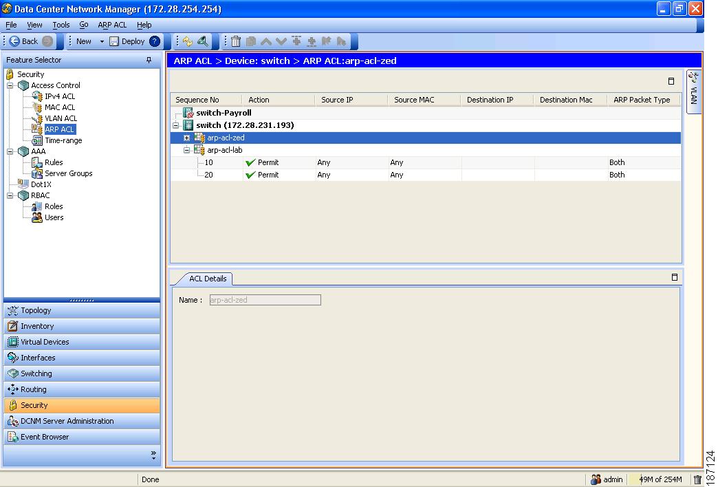
Figure 12-4 shows the ARP ACL content pane.
Figure 12-4 ARP ACL Content Pane
This section includes the following topics:
Creating an ARP ACL
You can create an ARP ACL on the device and add rules to it.
DETAILED STEPS
To create an ARP ACL on the device, follow these steps:
Step 1 ![]() From the Feature Selector pane, choose Security > Access Control > ARP ACL.
From the Feature Selector pane, choose Security > Access Control > ARP ACL.
Available devices appear in the Summary pane.
Step 2 ![]() From the Summary pane, double-click the device to which you want to add an ACL.
From the Summary pane, double-click the device to which you want to add an ACL.
Step 3 ![]() From the menu bar, choose File > New > ACL.
From the menu bar, choose File > New > ACL.
A blank row appears in the Summary pane. The Details tab appears in the Details pane.
Step 4 ![]() On the Details tab, in the Name field, type a name for the ACL.
On the Details tab, in the Name field, type a name for the ACL.
Step 5 ![]() For each rule or remark that you want to add to the ACL, from the menu bar, choose File > New and choose ACE or Remark. On the Details tab, configure fields as needed.
For each rule or remark that you want to add to the ACL, from the menu bar, choose File > New and choose ACE or Remark. On the Details tab, configure fields as needed.
Note ![]() To log packets that match a rule, check Log, complete the procedure, and then confirm that DAI logging for each VLAN that you apply the ACL to is configured to log packets when they match a rule in the ARP ACL. For more information, see the "Configuring DAI Log Filtering" section.
To log packets that match a rule, check Log, complete the procedure, and then confirm that DAI logging for each VLAN that you apply the ACL to is configured to log packets when they match a rule in the ARP ACL. For more information, see the "Configuring DAI Log Filtering" section.
Step 6 ![]() From the menu bar, choose File > Deploy to apply your changes to the device.
From the menu bar, choose File > Deploy to apply your changes to the device.
Changing an ARP ACL
You can change, reorder, add, and remove rules in an existing ARP ACL.
DETAILED STEPS
To change an ARP ACL, follow these steps:
Step 1 ![]() From the Feature Selector pane, choose Security > Access Control > ARP ACL.
From the Feature Selector pane, choose Security > Access Control > ARP ACL.
Available devices appear in the Summary pane.
Step 2 ![]() From the Summary pane, double-click the device that has the ACL that you want to change and then double-click the ACL.
From the Summary pane, double-click the device that has the ACL that you want to change and then double-click the ACL.
The ACLs on the device and the rules of the ACL that you double-clicked appear in the Summary pane.
Step 3 ![]() (Optional) If you want to change the details of a rule, click the rule in the Summary pane. On the Details tab, configure fields as needed.
(Optional) If you want to change the details of a rule, click the rule in the Summary pane. On the Details tab, configure fields as needed.
Note ![]() To log packets that match a rule, check Log, complete the procedure, and then confirm that DAI logging for each VLAN that you apply the ACL to is configured to log packets when they match a rule in the ARP ACL. For more information, see the "Configuring DAI Log Filtering" section.
To log packets that match a rule, check Log, complete the procedure, and then confirm that DAI logging for each VLAN that you apply the ACL to is configured to log packets when they match a rule in the ARP ACL. For more information, see the "Configuring DAI Log Filtering" section.
Step 4 ![]() (Optional) If you want to add a rule or remark, click the ACL in the Summary pane and then from the menu bar, choose File > New and choose ACE or Remark. On the Details tab, configure fields as needed.
(Optional) If you want to add a rule or remark, click the ACL in the Summary pane and then from the menu bar, choose File > New and choose ACE or Remark. On the Details tab, configure fields as needed.
Step 5 ![]() (Optional) If you want to remove a rule, click the rule and then from the menu bar, choose ARP ACL > Delete.
(Optional) If you want to remove a rule, click the rule and then from the menu bar, choose ARP ACL > Delete.
Step 6 ![]() (Optional) If you want to move a rule or remark to a different position in the ACL, click the rule or remark and then from the menu bar, choose one of the following, as applicable:
(Optional) If you want to move a rule or remark to a different position in the ACL, click the rule or remark and then from the menu bar, choose one of the following, as applicable:
•![]() ARP ACL > Move Up
ARP ACL > Move Up
•![]() ARP ACL > Move Down
ARP ACL > Move Down
The rule moves up or down, as you chose. The sequence number of the rules adjust accordingly.
Step 7 ![]() From the menu bar, choose File > Deploy to apply your changes to the device.
From the menu bar, choose File > Deploy to apply your changes to the device.
Removing an ARP ACL
You can remove an ARP ACL from the device.
BEFORE YOU BEGIN
Ensure that you know whether the ACL is applied to a VLAN. The device allows you to remove ACLs that are currently applied. Removing an ACL does not affect the configuration of VLANs where you have applied the ACL. Instead, the device considers the removed ACL to be empty.
DETAILED STEPS
To remove an ARP ACL from the device, follow these steps:
Step 1 ![]() From the Feature Selector pane, choose Security > Access Control > ARP ACL.
From the Feature Selector pane, choose Security > Access Control > ARP ACL.
Available devices appear in the Summary pane.
Step 2 ![]() From the Summary pane, double-click the device from which you want to remove an ACL.
From the Summary pane, double-click the device from which you want to remove an ACL.
The ACLs currently on the device appear in the Summary pane.
Step 3 ![]() Click the ACL that you want to remove.
Click the ACL that you want to remove.
Step 4 ![]() From the menu bar, choose ARP ACL > Delete.
From the menu bar, choose ARP ACL > Delete.
The ACL disappears from the Summary pane.
Step 5 ![]() From the menu bar, choose File > Deploy to apply your changes to the device.
From the menu bar, choose File > Deploy to apply your changes to the device.
Field Descriptions for ARP ACLs
This section includes the following topics:
•![]() ARP Access Rule: ACE Details Tab
ARP Access Rule: ACE Details Tab
•![]() ARP Access Rule: ACE Details: Source and Destination Section
ARP Access Rule: ACE Details: Source and Destination Section
•![]() ARP ACL Remark: Remark Details Tab
ARP ACL Remark: Remark Details Tab
ARP ACL: ACL Details Tab
ARP Access Rule: ACE Details Tab
ARP Access Rule: ACE Details: Source and Destination Section
ARP ACL Remark: Remark Details Tab
Related Fields
For information about fields that apply ARP ACLs, see the "VLAN: DAI VLAN Details Tab" section.
Additional References
For additional information related to implementing DAI, see the following sections:
Related Documents
|
|
|
|---|---|
DHCP snooping |
Standards
|
|
|
|---|---|
RFC-826 |
An Ethernet Address Resolution Protocol (http://tools.ietf.org/html/rfc826) |
Feature History for DAI
Table 12-8 lists the release history for this feature.
|
|
|
|
|---|---|---|
DAI |
4.1(2) |
No change from Release 4.0. |
 Feedback