Best Practices for Deploying Cisco DCNM and Computes
This chapter describes the document best practices to deploy Cisco DCNM OVA and ISO in clustered and unclustered modes. The following sections explain the recommended design for configurations of IP addresses and relevant IP pools during the Cisco DCNM installation.
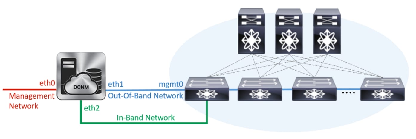
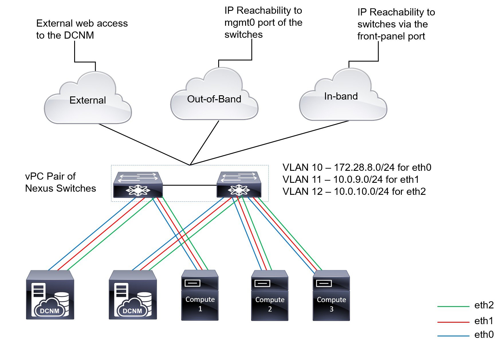
The Cisco DCNM OVA or the ISO installation consists of 3 network interfaces:
-
dcnm-mgmt network (eth0) interface
This network provides connectivity (SSH, SCP, HTTP, HTTPS) to the Cisco DCNM.
-
enhanced-fabric-mgmt (eth1) interface
This network provides enhanced fabric management of Cisco Nexus switches through the out-of-band or mgmt0 interface.
-
enhanced-fabric-inband (eth2) interface
This network provides in-band connection to the fabric through the front-panel ports. This network interface is used for applications such as Endpoint Locator (EPL) and Network Insights Resources (NIR).
The following figure shows the network diagram for the Cisco DCNM management interfaces.
Guidelines to Use the Best Practices
The following are the guidelines to remember while you use the best practices for deploying DCNM and Computes.
-
The IP addresses specified in this document are sample addresses. Ensure that your setup reflects the IP addresses used in the production network.
-
Ensure that the eth2 interface subnet is different from the subnet that is associated with the eth0 interface and the eth1 interface.
-
As eth0 and eth1 interfaces are both on the same subnet, the DHCP returns the same IP address, two responses but same for both queries.
-
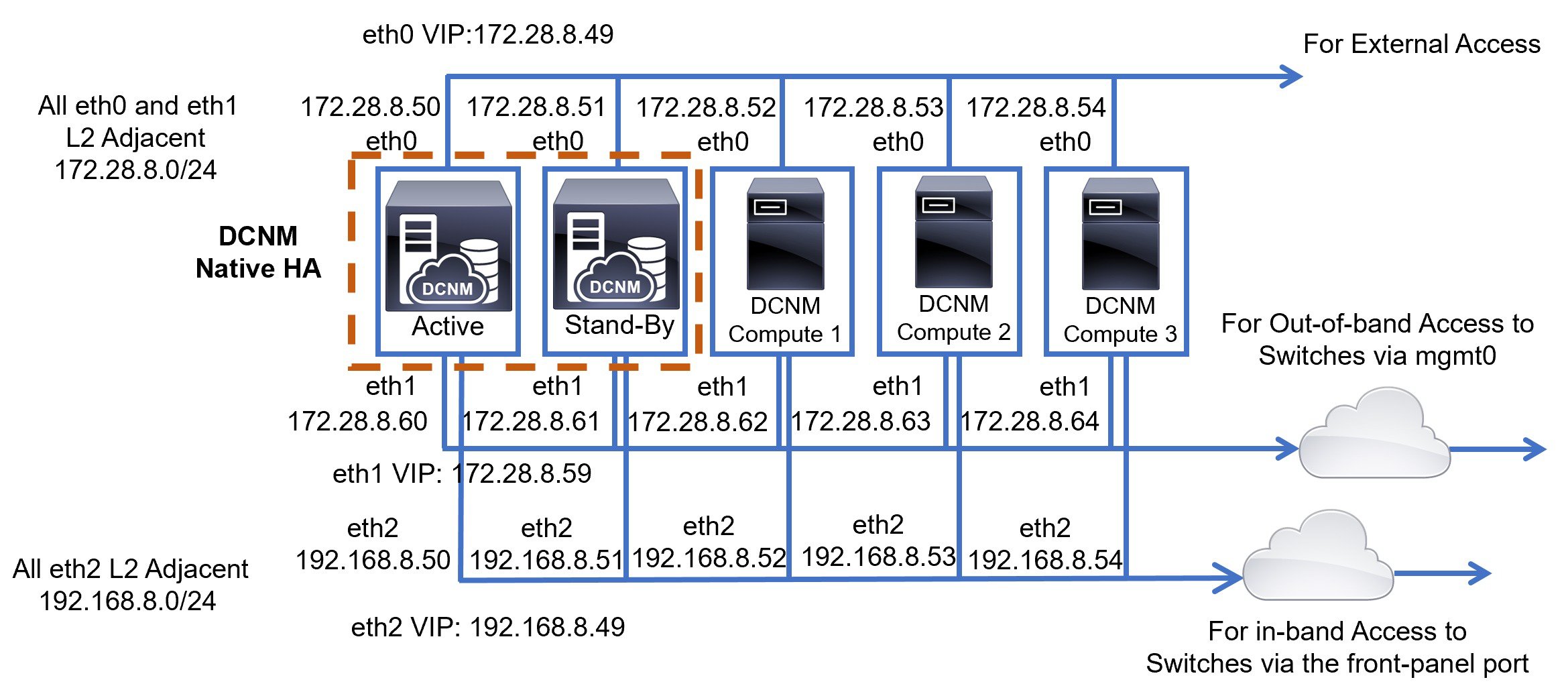
Cisco DCNM Native HA consists of two Cisco DCNM appliances, that run as Active and Standby applications. The embedded databases of both Active and Standby appliances are synchronized in real time. The eth0, eth1, and eth2 interfaces of the Cisco DCNM and Compute nodes, in a clustered mode, must be Layer-2 adjacent.
-
For information about Cluster Mode in your Cisco DCNM Deployment, refer to Applications chapter in the Cisco DCNM Configuration Guide for your deployment type.
Deployments for Redundancy in Cisco DCNM
This section describes the recommended deployments for redundancy of DCNM operations. As a general assumption, the DCNM and the compute nodes are installed as Virtual Machines. During Cisco DCNM ISO installation on Virtual Appliance on UCS (Bare Metal), all DCNMs and computes have their own individual servers.
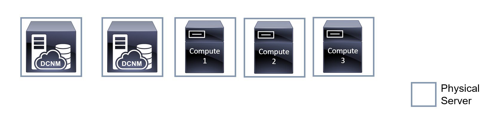
Deployment 1: Minimum Redundancy Configuration
The recommended configuration for minimum redundancy in a Cisco DCNM Cluster mode installation is as follows:
-
DCNM Active Node and Compute Node 1 in Server 1
-
DCNM Standby Node and Compute Node 2 in Server 2
-
Compute Node 3 in Server 3
-
Compute VMs deployed on an exclusive disk
-
No oversubscription of memory or CPU of the physical servers

Deployment 2: Maximum Redundancy Configuration
The recommended configuration for maximum redundancy in a DCNM Cluster mode installation is as follows:
-
DCNM Active Node(Active) in Server 1
-
DCNM Standby Node in Server 2
-
Compute Node 1 in Server 3
-
Compute Node 2 in Server 4
-
Compute Node 3 in Server 5
IP Address Configurations in Cisco DCNM
This section describes the best practices and recommended deployments for IP address configurations of all interfaces of the Cisco DCNM and Compute nodes.
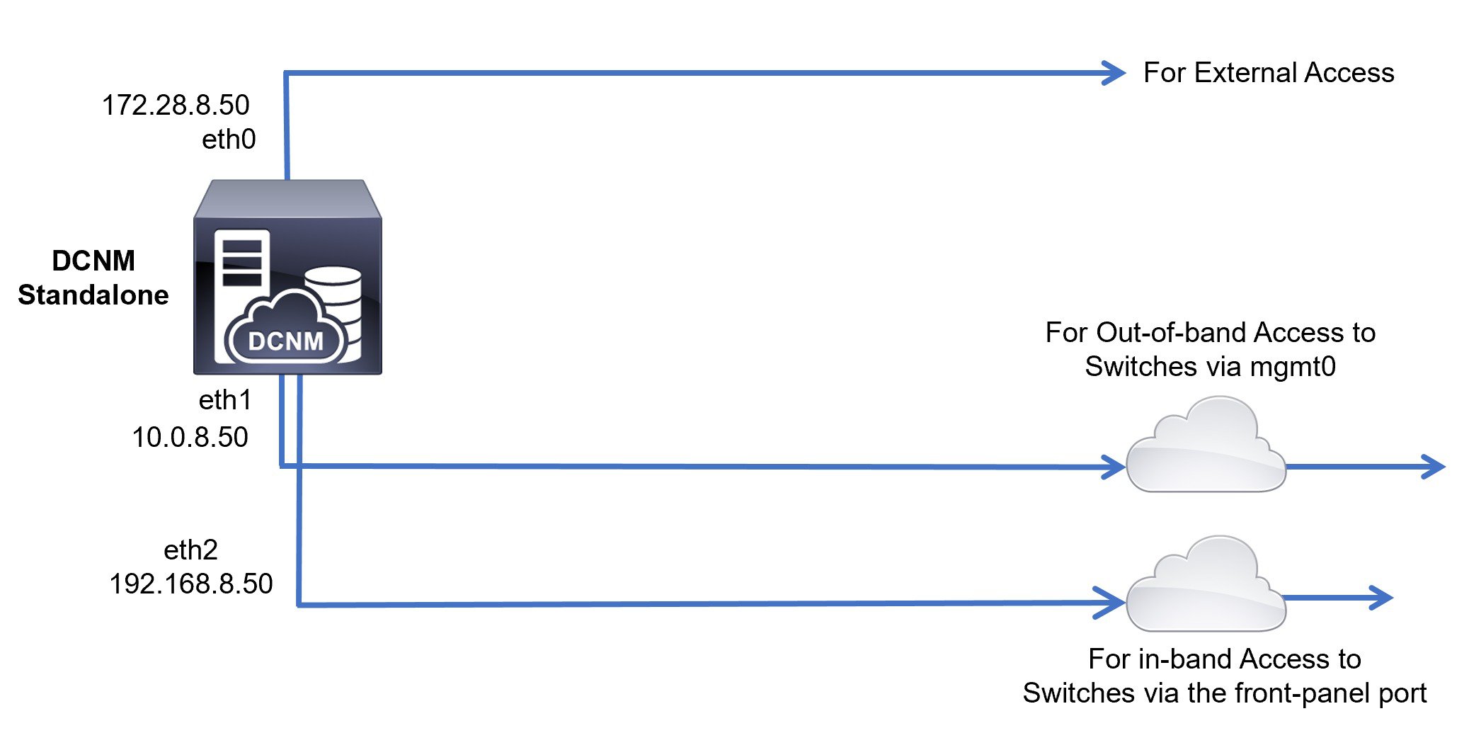
Scenario 1: All 3 Ethernet Interfaces are in Different Subnets
In this scenario, consider all three Ethernet interfaces of DCNM on different subnets.
For example:
-
eth0 – 172.28.8.0/24
-
eth1 – 10.0.8.0/24
-
eth2 – 192.168.8.0/24
The possible deployments are as follows:
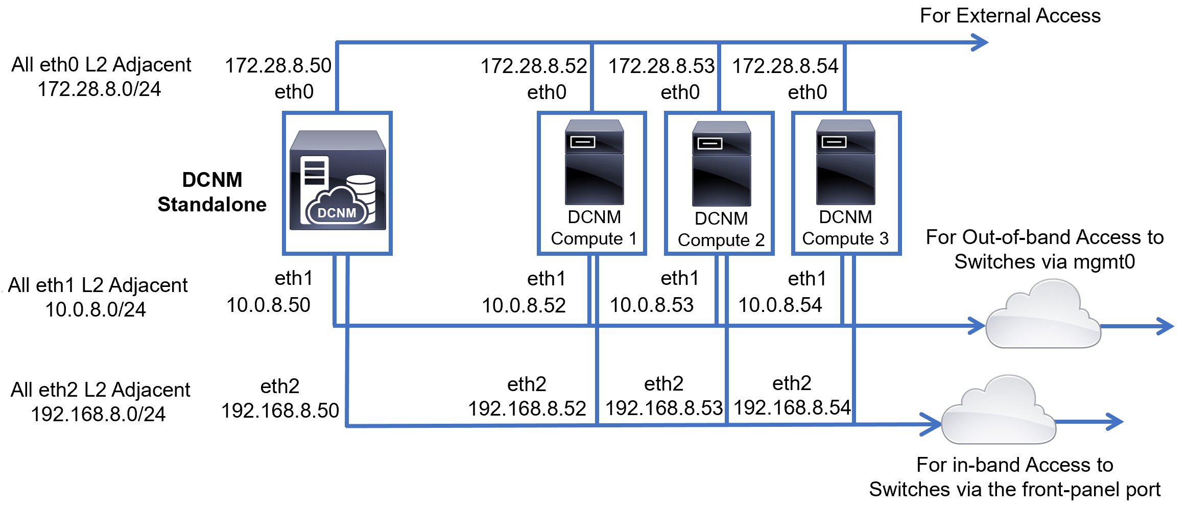
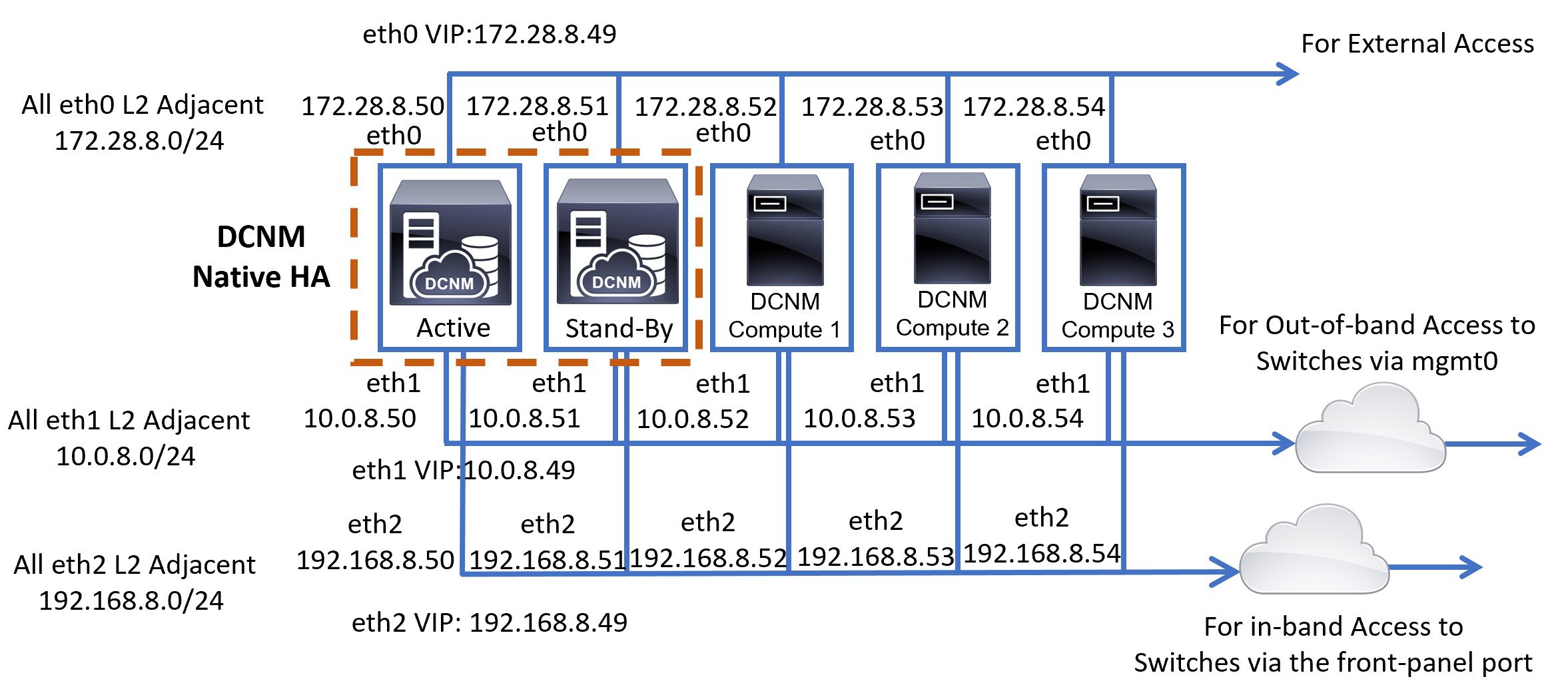
Cisco DCNM Unclustered mode
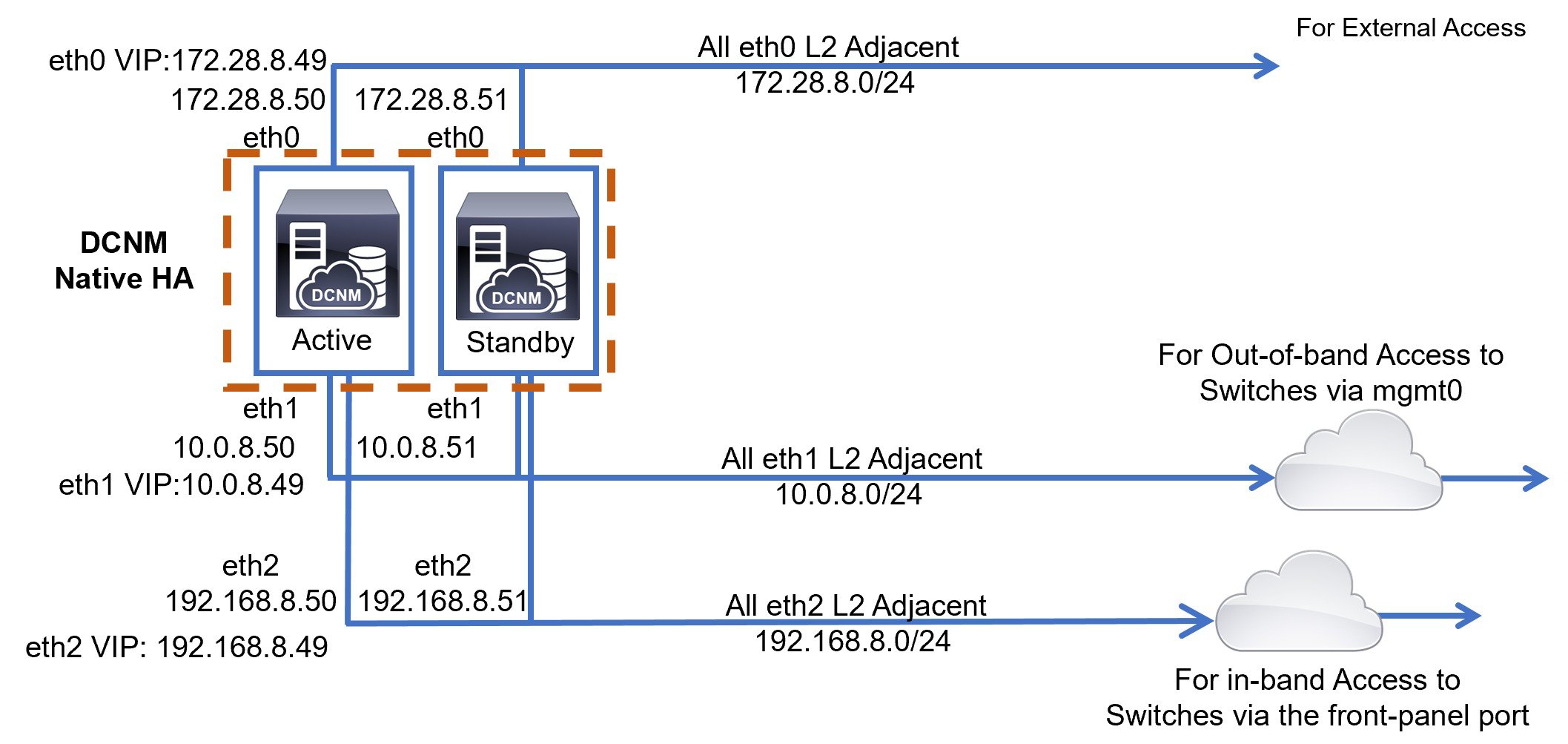
Cisco DCNM Clustered Mode
Scenario 2: eth2 Interface in Different Subnet
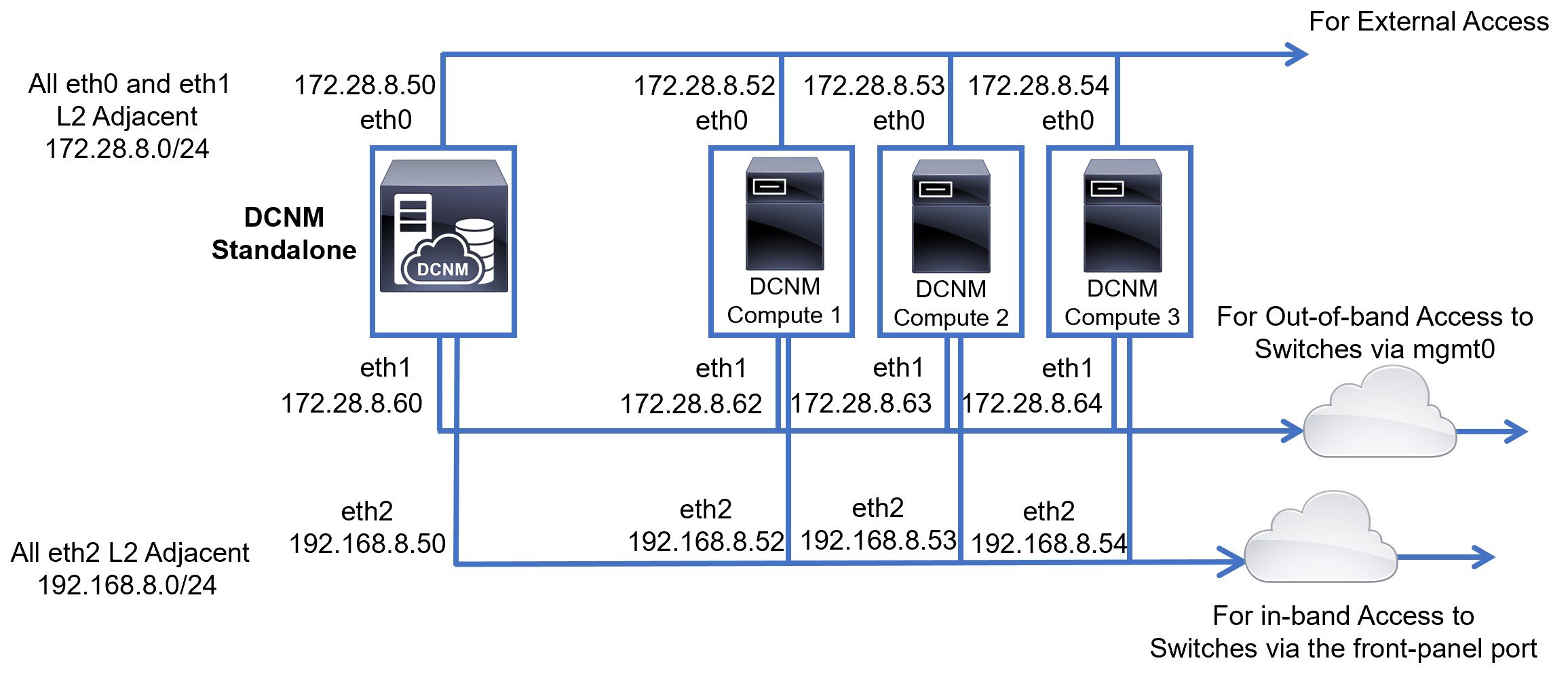
In this scenario, consider that the eth0 and eth1 interfaces are in the same subnet, and eth2 interfaces of DCNMs and Computes are in a different subnet.
For example:
-
eth0 – 172.28.8.0/24
-
eth1 – 172.28.8.0/24
-
eth2 – 192.168.8.0/24
The possible deployments are as follows:
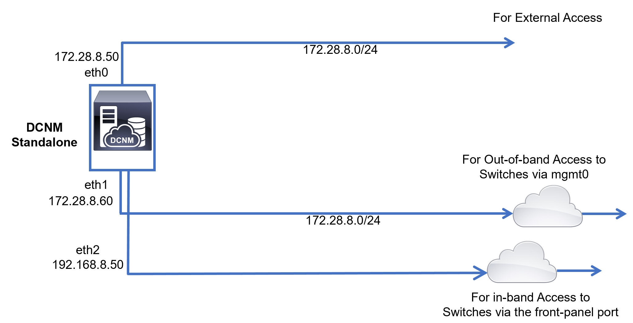
Cisco DCNM Unclustered Mode
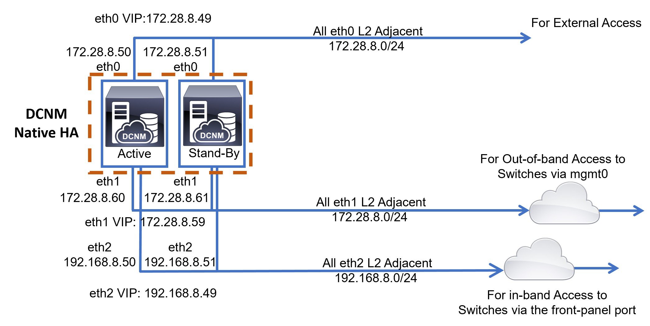
Cisco DCNM Clustered Mode
Physical Connectivity of Cisco DCNM and Compute Nodes
This section describes the physical connectivity of the Cisco DCNM and Compute nodes in both Virtual Machines and Bare Metal installations.
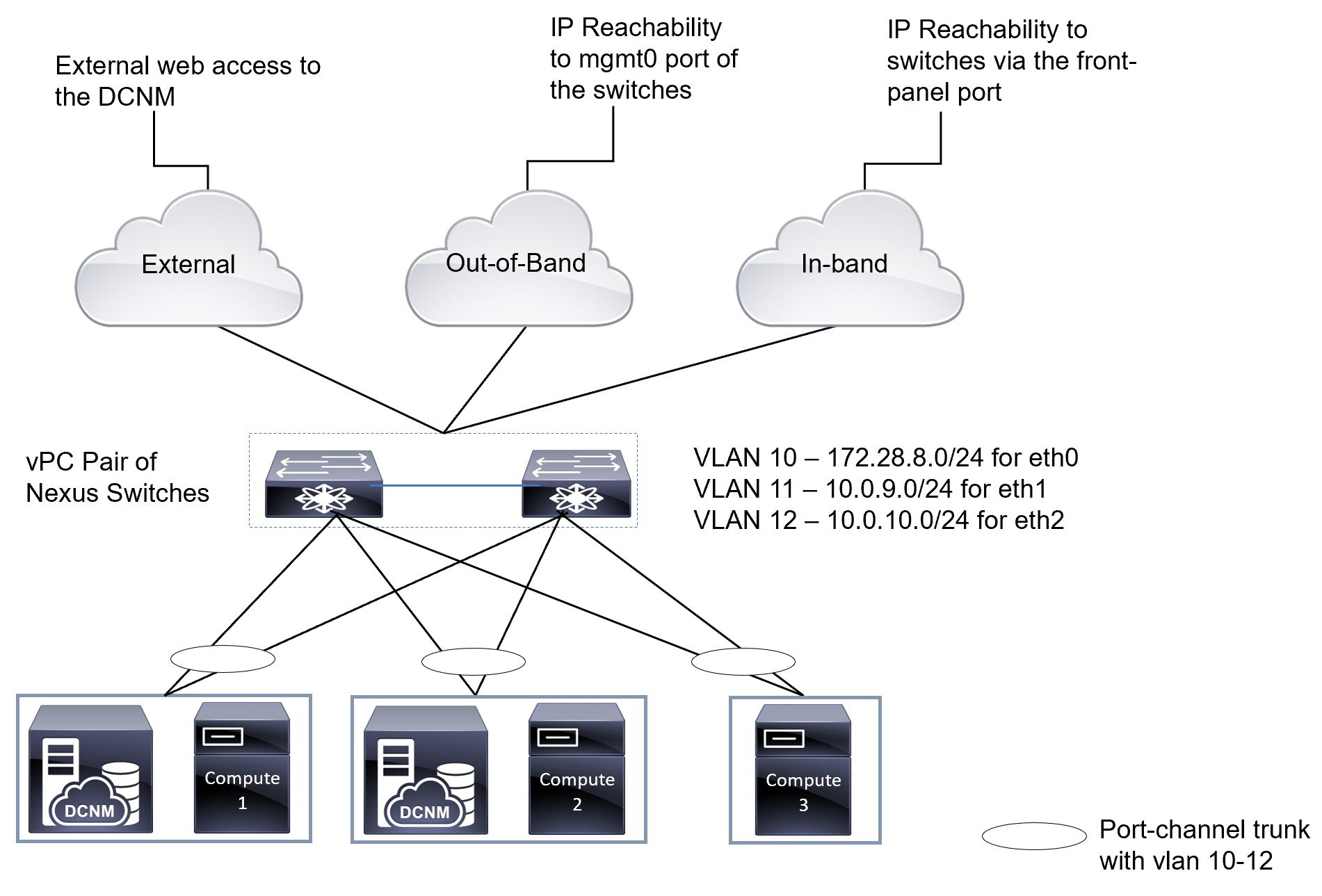
Virtual Machines
The following image shows the physical connectivity of DCNM and compute nodes supported in a 3 server redundancy configuration. The physical servers must be connected to a vPC pair of switches via port-channels. This provides adequate fault-tolerance, if a single link fails or a single switch fails. The vPC pair of switches is considered as the infra vPC pair that provides management connectivity to the physical servers.
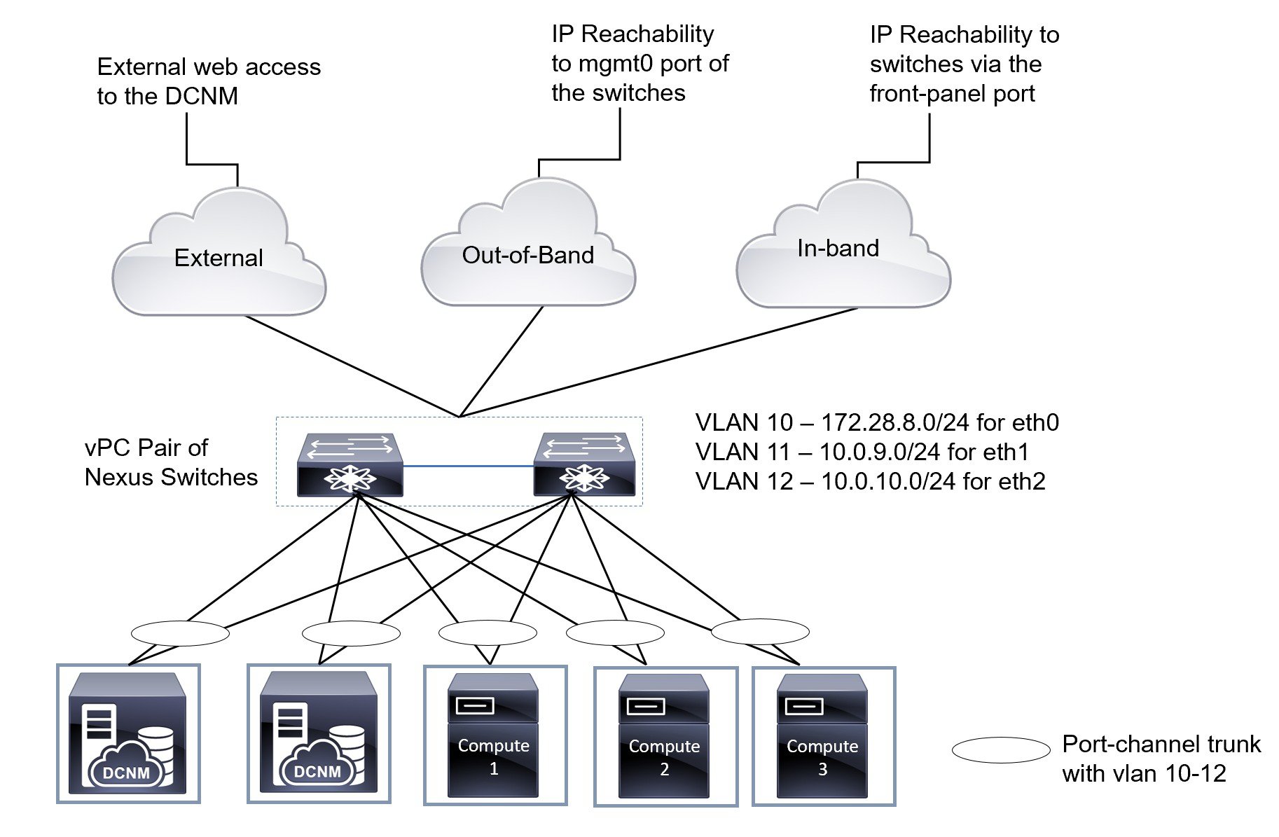
The following image shows the physical connectivity of Cisco DCNM and Compute nodes supported in an VM installation in a 5 server redundancy configuration.
Bare Metal Installation
For installing Cisco DCNM on Bare Metal, 5 servers are required. The following image shows the physical connectivity of Cisco DCNM and Compute nodes. Note that, there are 3 physical interfaces on each server that map to the eth0, eth1, and eth2 interfaces, respectively. If the physical server consists of a managed network adapter such as the Cisco UCS VIC 1455 Virtual Interface Card, you can have a port-channel connectivity from the servers to the switches, similar to the Virtual Machines.
 Feedback