Fabrics
This section contains context-sensitive Online Help content for the Control > Fabrics tab. It has the following submenu:
VXLAN BGP EVPN Fabrics Provisioning
In DCNM 11.0, fabric creation is enhanced. In addition to overlay networks, you can also provision VXLAN BGP EVPN underlay network parameters to the fabric switches. Also, the concept of Multi-Site Domain (MSD) fabrics is introduced. The DCNM GUI is updated as follows:
Control > Fabric Builder menu option (under the Fabrics sub menu).
Fabric creation and updation:
-
Create new standalone and MSD fabrics.
-
Create an external fabric. The external network is representative of connections between the border devices of the fabric and the external fabric.
-
View the list of fabrics that are already created and edit the overlay and underlay network ranges of the fabric, and the policy templates.
Device discovery and provisioning start-up configurations on new switches:
-
Discover switches and the fabric topology. Also, provision start-up configurations and an IP address to a new switch through POAP configuration.
-
Delete the fabrics.
Control > Interfaces menu option (under the Fabrics sub menu).
Underlay provisioning:
-
Create, deploy, view, edit and delete a port-channel, vPC switch pair, straight through FEX, AA FEX, loopback, and sub interface.
-
Create breakout and unbreakout ports.
-
Shut down and bring up interfaces.
-
Rediscover ports and view interface configuration history.
-
Designate a switch interface as a routed port, trunk port, OSPF interface, and so on.
Control > Networks & VRFs menu option (under the Fabrics sub menu).
Overlay network provisioning.
-
Create new overlay networks and VRFs (from the range specified in fabric creation).
-
Provision the overlay networks and VRFs on the switches of the fabric.
-
Undeploy the networks and VRFs from the switches.
-
Remove the provisioning from the fabric in DCNM.
Control > Migration menu option (under the Fabrics sub menu).
NFM fabric migration to the VXLAN BGP EVPN fabric.
-
In DCNM 10.4(2) release, Cisco Nexus Fabric Manager (NFM) fabric overlay migration to DCNM was introduced. In DCNM 11.0 release, NFM fabric underlay migration to DCNM has also been introduced.
This chapter covers all standalone fabric-related configurations. MSD fabric documentation is available in a separate chapter. Step by step configuration:
Create a New VXLAN BGP EVPN Fabric
-
Choose Control > Fabric Builder.
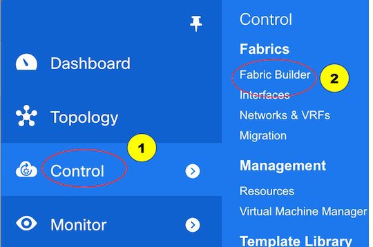
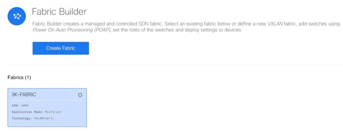
The Fabric Builder window appears. When you log in for the first time, the Fabrics section has no entries. After you create a fabric, it is displayed on the Fabric Builder window, wherein a rectangular box represents each fabric.

A standalone or member fabric contains Switch_Fabric in the Type field, the AS number in the ASN field, and mode of replication in the Replication Mode field.
-
Click Create Fabric. The Add Fabric window appears.
Enter the name of the fabric in the Fabric Name field, and choose a template according to the type of fabric you want from the drop-down menu in Fabric Template.
Choose Easy_Fabric. The fabric creation window for creating a standalone fabric comes up.
The tabs and their fields in the screen are explained in the subsequent points. The overlay and underlay network parameters are included in these tabs.

Note
If you are creating a standalone fabric as a potential member fabric of an MSD fabric (used for provisioning overlay networks for fabrics that are connected through EVPN Multi-Site technology), then browse through the overview of the MSD document before member fabric creation.
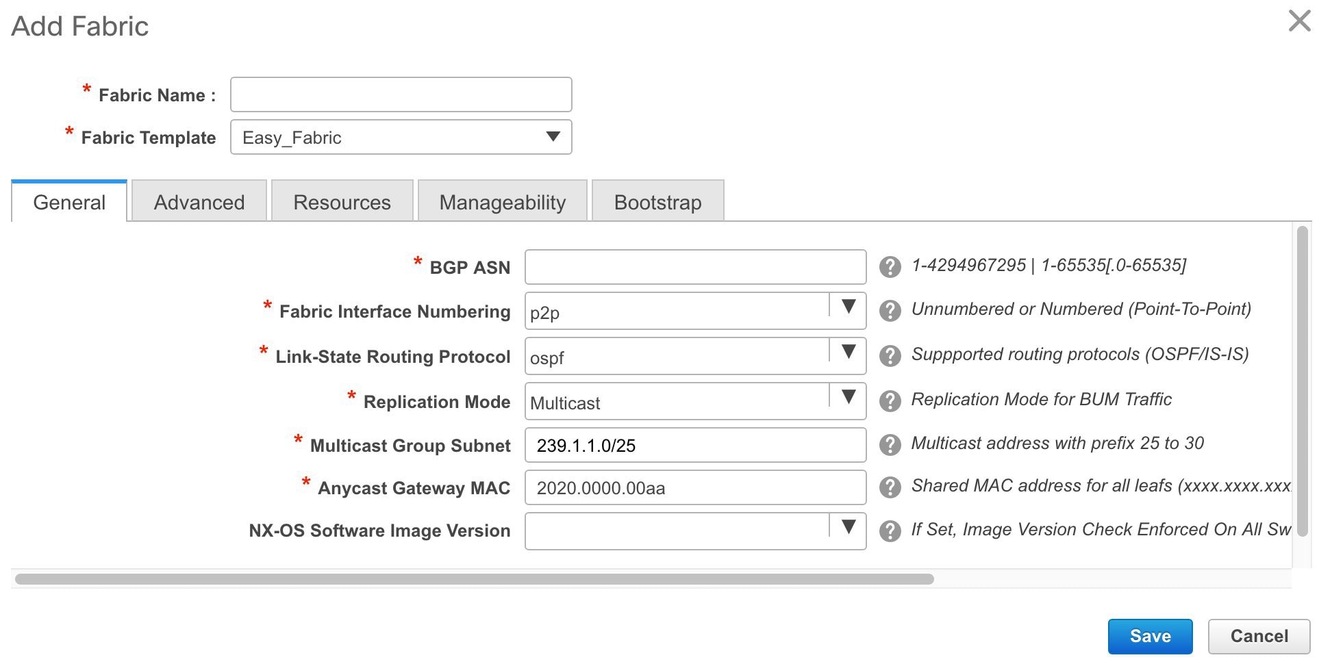
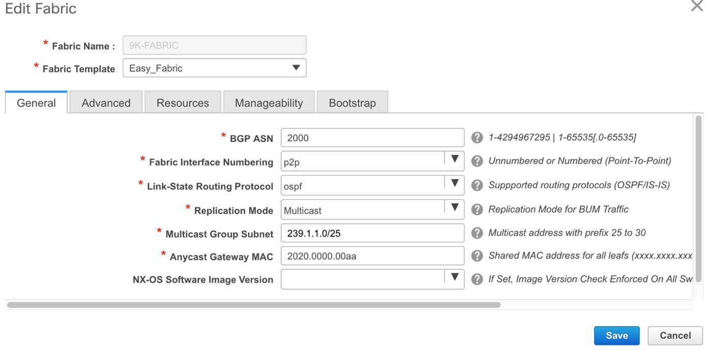
- The General tab is displayed by default. The fields in this tab are:
BGP ASN: Enter the BGP AS number the fabric is associated with.
Fabric Interface Numbering : Specifies whether you want to use point-to-point or unnumbered networks.
Link-State Routing Protocol : The IGP used in the fabric, OSPF, or IS-IS.
Replication Mode : The mode of replication that is used in the fabric, Ingress Replication, or Multicast.
Multicast Group Subnet : Multicast group address of the network.
Anycast Gateway MAC : Anycast gateway MAC address.
NX-OS Software Image Version : Select an image from the list.
If you upload Cisco NX-OS software images through the image upload option, the uploaded images are listed in this field. If you select an image, the system checks if the switch has the selected version. If not, an error message is displayed. You can resolve the error by clicking on Resolve. The image management screen comes up and you can proceed with the ISSU option. Alternatively, you can delete the release number and save it later.
If you specify an image in this field, all switches in the fabric must run that image. If some devices do not run the image, a warning is prompted to perform an In-Service Software Upgrade (ISSU) to the specified image. Until all devices run the specified image, the deployment process is incomplete.
If you want to deploy more than one type of software image on the fabric switches, don’t specify any image. If an image is specified, delete it.
-
Click the Advanced tab. Most of the fields are auto generated. You can update the fields if needed.
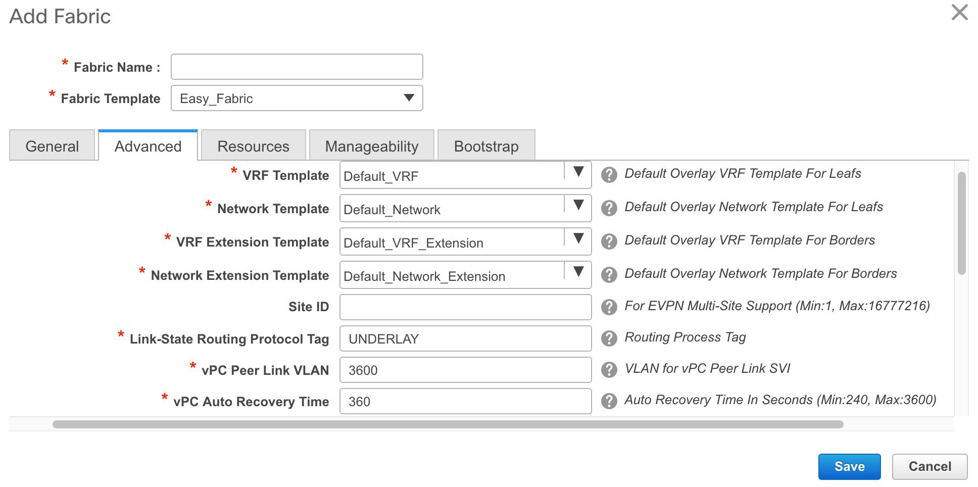
VRF Template : Specifies the VRF template for the overlay networks.
Network Template : Specifies the network template for the overlay networks.
VRF Extension Template: Specifies the VRF extension template for extending the overlay networks to other fabrics.
Network Extension Template : Specifies the network extension template for extending the overlay networks to other fabrics.
Site ID : The ID for this fabric if you are moving this fabric within an MSD. The site ID is mandatory for a member fabric to be a part of an MSD. Each member fabric of an MSD has a unique site ID for identification.
Link-State Routing Protocol Tag : The tag defining the type of network.
vPC Peer Link VLAN : VLAN used for the vPC peer link SVI.
vPC Auto Recovery Time : Specifies the vPC auto recovery time-out period in seconds.
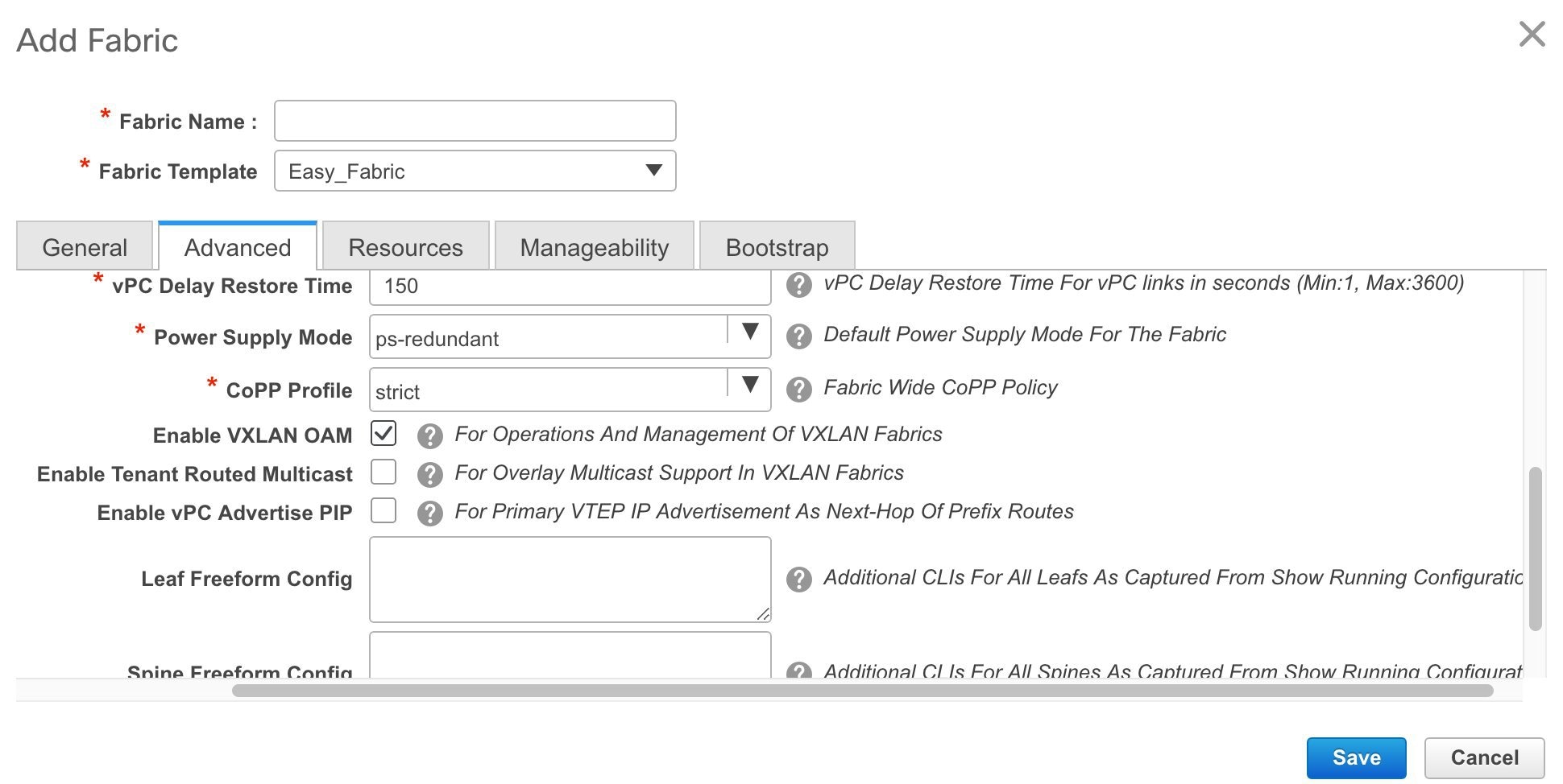
vPC Delay Restore Time - Specifies the vPC delay restore period in seconds.
Power Supply Mode - Choose the appropriate power supply mode.
CoPP Profile - Choose the appropriate Control Plane Policing (CoPP) profile policy for the fabric. By default, the strict option is populated.
Enable VXLAN OAM - Enables the VXLAM OAM function.
Note
The VXLAN OAM feature in Cisco DCNM is only supported on a single fabric or site.
Enable Tenant Routed Multicast - Enables overlay multicast protocol support in the fabric.
Enable vPC Advertise PIP - Enables the Advertise PIP feature.
Freeform CLIs - Fabric level freeform CLIs can be added while creating or editing a fabric. They are applicable to switches across the fabric. You must add the configurations as displayed in the running configuration, without indentation. Switch level freeform configurations such as VLAN, SVI, and interface configurations should only be added on the switch. Refer the Freeform Configurations on Fabric Switches topic for a detailed explanation and examples.
Leaf Freeform Config - Add CLIs that should be added to switches that have the Leaf, Border, and Border Gateway roles.
Spine Freeform Config - Add CLIs that should be added to switches with a Spine role.
- Click the Resources tab.
The fields in this tab are: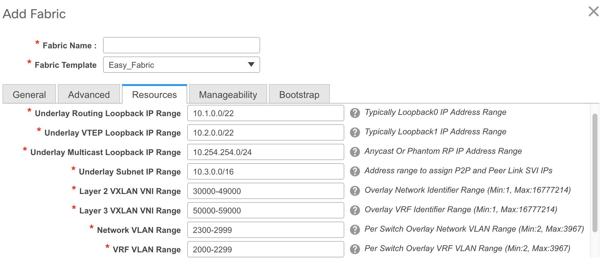
Underlay Routing Loopback IP Range - Specifies loopback IP addresses for the protocol peering.
Underlay VTEP Loopback IP Range - Specifies loopback IP addresses for VTEPs.
Underlay Multicast Loopback IP Range - Specifies loopback IP addresses for multicast routing.
Underlay Subnet IP Range - IP addresses for underlay P2P routing traffic between interfaces.
Layer 2 VXLAN VNI Range and Layer 3 VXLAN VNI Range - Specifies the VXLAN VNI IDs for the fabric.
Network VLAN Range and VRF VLAN Range - VLAN ranges for the Layer 3 VRF and overlay network.
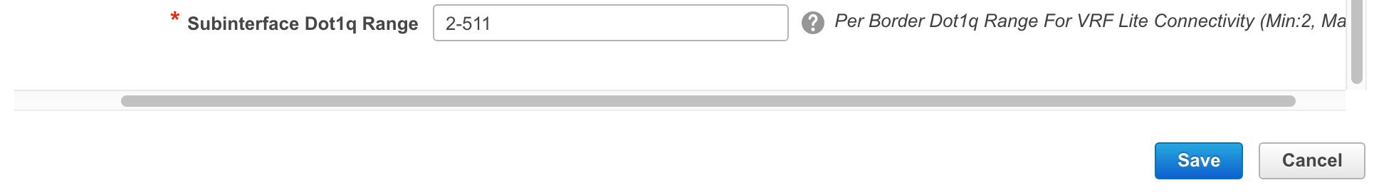
Subinterface Dot1q Range - Specifies the subinterface range when L3 sub interfaces are used.
Note
The values shown in the screen shot are automatically generated. If you want to update the IP address ranges, VXLAN Layer 2/Layer 3 network ID ranges or the VRF/Network VLAN ranges, ensure the following:
If you update a range of values, ensure that it does not overlap with other ranges.
You must only update one range of values at a time. If you want to update more than one range of values, do it in separate instances. For example, if you want to update L2 and L3 ranges, you should do the following.
-
Update the L2 range and click Save.
-
Click the Edit Fabric option again, update the L3 range and click Save.
-
-
Click the Manageability tab.
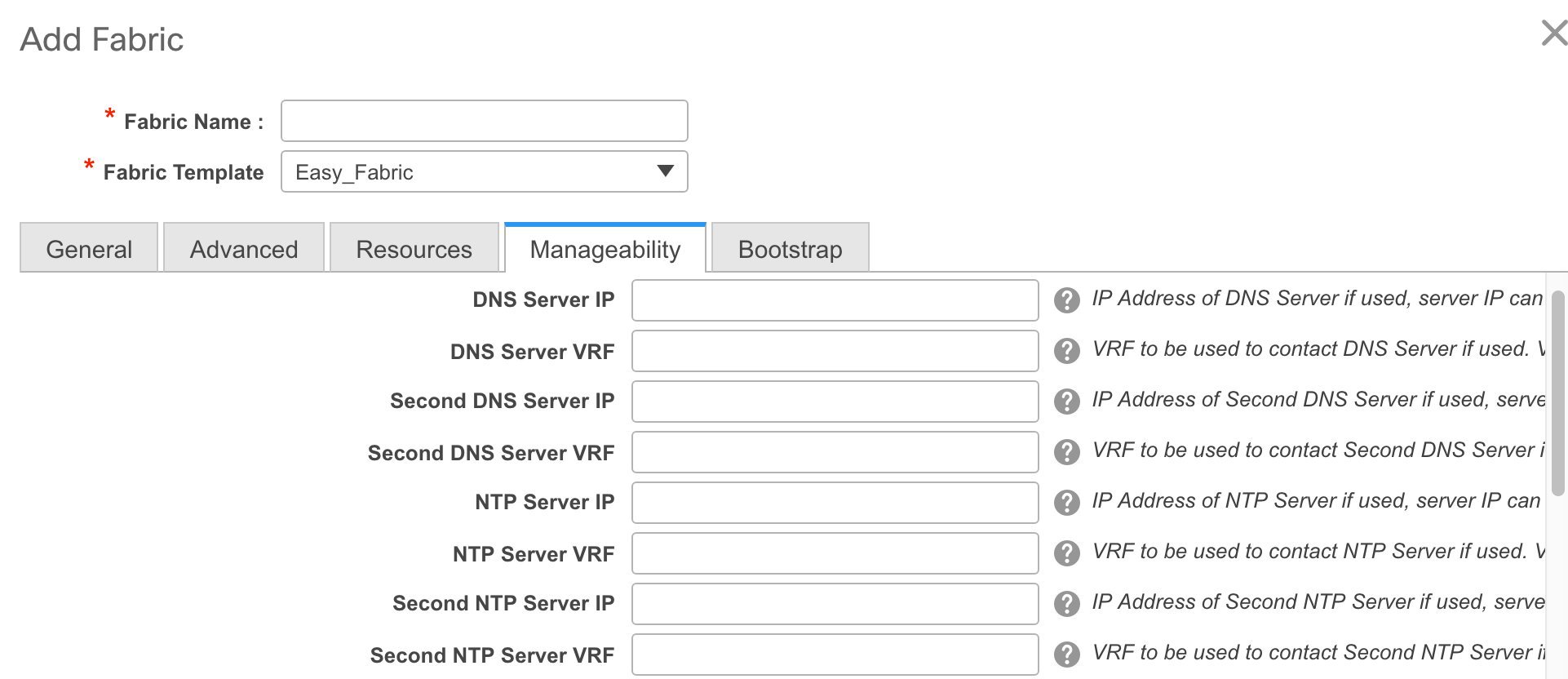
The fields in this tab are:
DNS Server IP - Specifies the IP address of the DNS server, if you use a DNS server.
DNS Server VRF - Specifies the VRF to be used to contact the DNS server IP address.
Second DNS Server IP - Specifies the IP address of the second DNS server, if you use a second DNS server.
Second DNS Server VRF - Specifies the VRF to be used to contact the second DNS server IP address.
NTP Server IP - Specifies the IP address of the NTP server, if you use an NTP server.
NTP Server VRF - Specifies the VRF to be used to contact the NTP server IP address.
Second NTP Server IP - Specifies the IP address of the second NTP server, if you use a second NTP server.
Second NTP Server VRF - Specifies the VRF to be used to contact the second NTP server IP address.
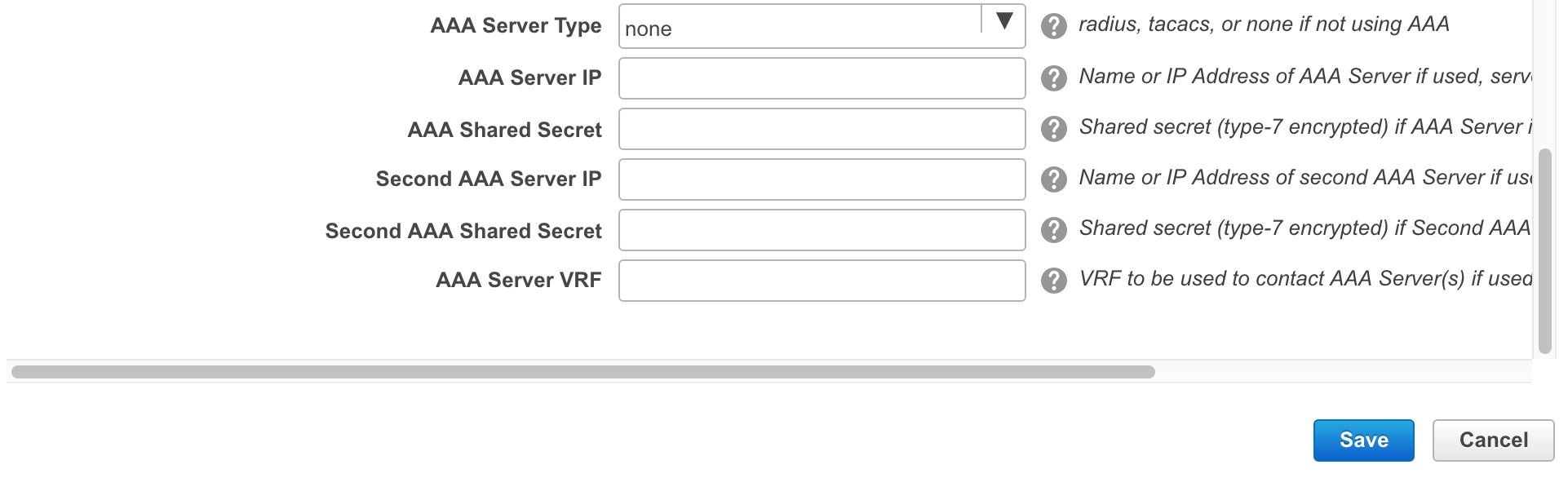
AAA Server Type - Specifies the AAA server type. By default, no type is populated. You can select a radius or TACACS server.
AAA Server IP - Specifies the IP address of the AAA server, if you use a AAA server.
AAA Shared Secret - Specifies the shared secret of the AAA server, if used.
Note
After fabric creation and discovery of switches, you must update the AAA server password on each fabric switch.
Second AAA Server IP - Specifies the IP address of the second AAA server, if you use a second AAA server.
Second AAA Shared Secret - Specifies the shared secret of the second AAA server, if used.
AAA Server VRF - Specifies the VRF to be used to contact the AAA server IP address.
- Click the Bootstrap tab.
The fields on this tab are: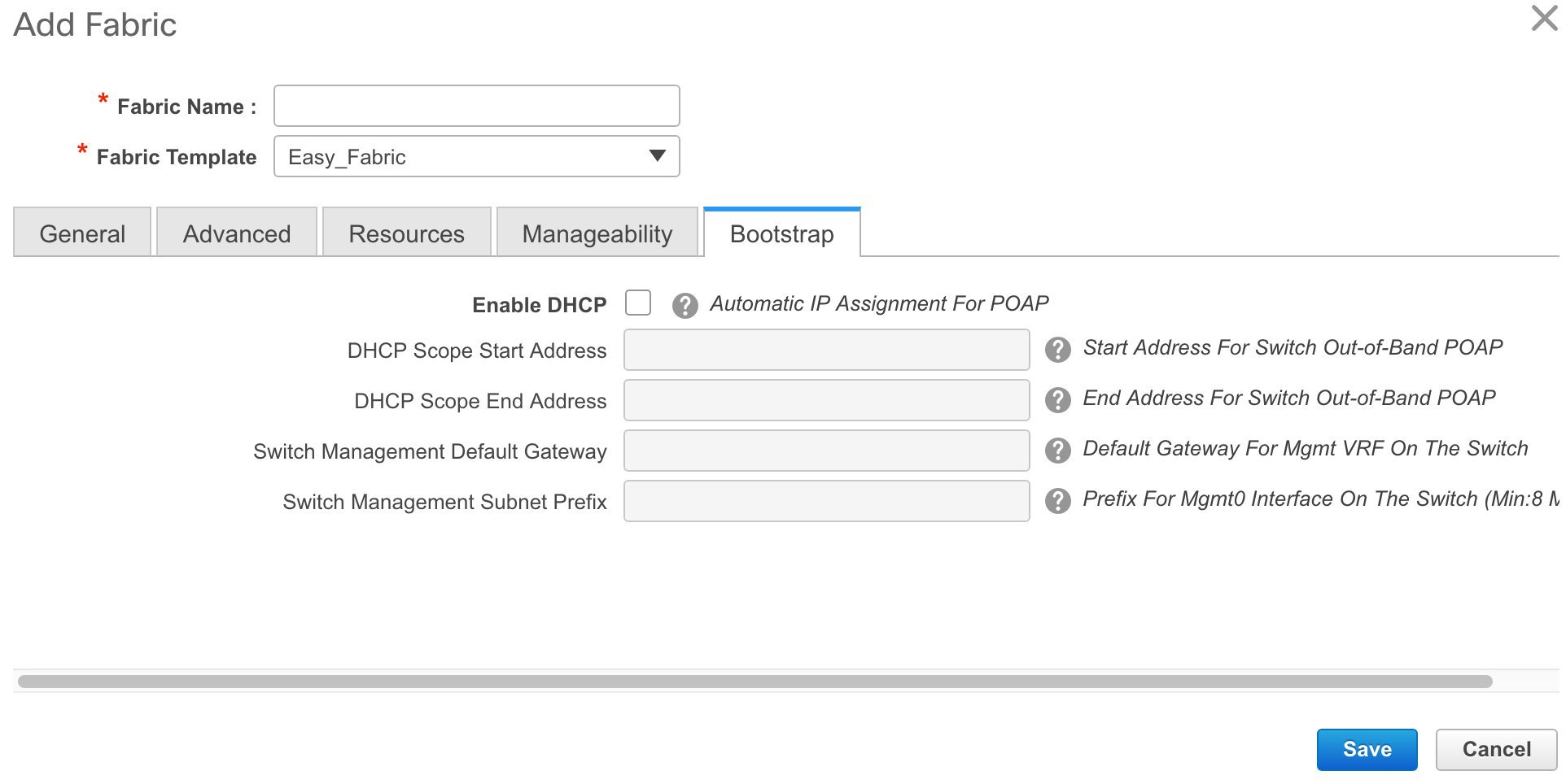
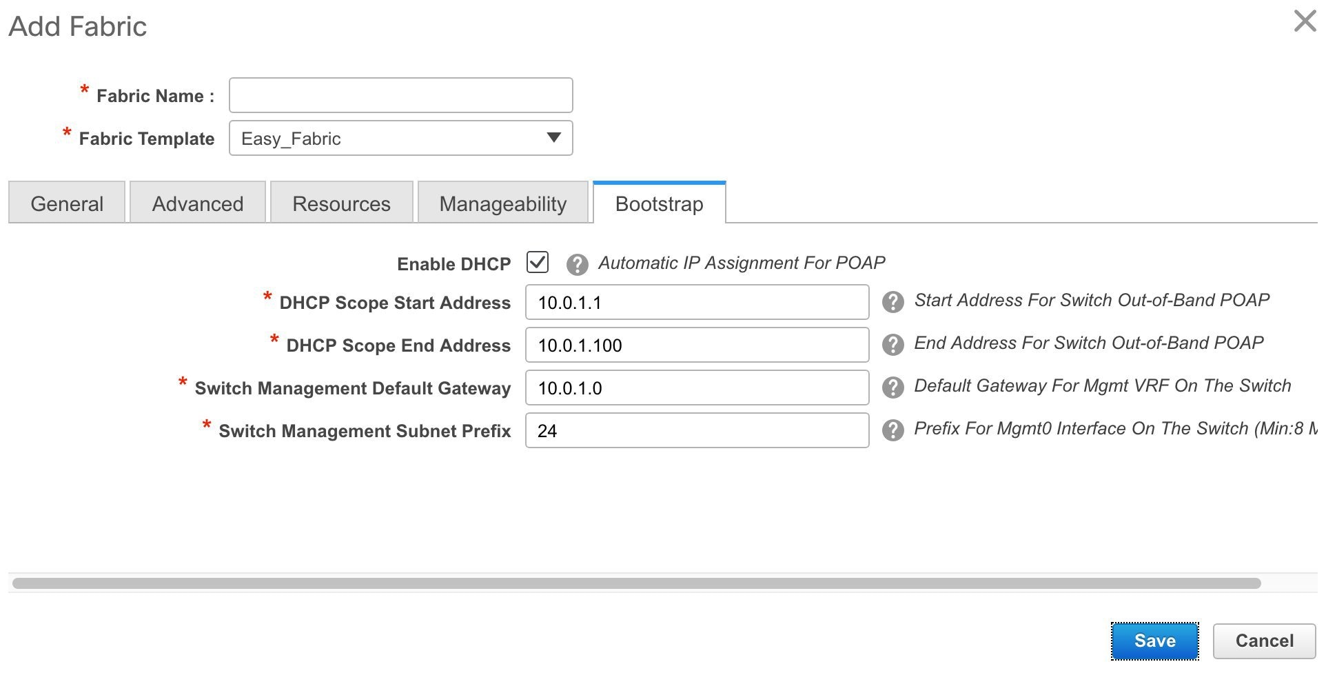
Enable DHCP - Click this check box to initiate enabling of automatic IP address assignment through DHCP. When you click the check box, the other fields become editable. They are:
DHCP Scope Start Address and DHCP Scope End Address - Specifies the first and last IP addresses of the IP address range to be used for the switch out of band POAP.
Switch Management Default Gateway - Specifies the default gateway for the management VRF on the switch.
Switch Management Subnet Prefix - Specifies the prefix for the Mgmt0 interface on the switch. The prefix should be between 8 and 30.
DHCP scope and management default gateway IP address specification - If you specify the management default gateway IP address 10.0.1.0 and subnet mask 24, ensure that the DHCP scope is within the specified subnet, between 10.0.1.1 and 10.0.1.254.
-
Click Save after filling and updating relevant information. A note appears briefly at the bottom right part of the screen, indicating that the fabric is created. When a fabric is created, the fabric page comes up. The fabric name appears at the top left part of the screen.
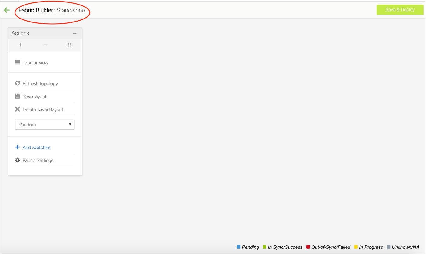
(At the same time, the newly created fabric instance appears on the Fabric Builder page. To go to the Fabric Builder page, click the left arrow (←) button above the Actions panel [to the left of the screen]).
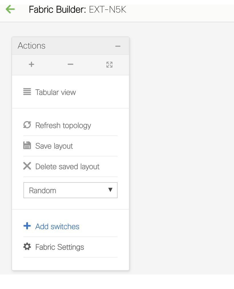
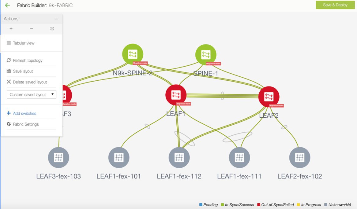
The Actions panel at the left part of the screen allows you to perform various functions. One of them is the Add switches option to add switches to the fabric. After you create a fabric, you should add fabric devices. The other options are:
-
Tabular View - By default, the switches are displayed in the topology view. Use this option to view switches in the tabular view.
-
Refresh topology - Allows you to refresh the topology.
-
You can choose between Hierarchical, Random and Custom saved layout display options.
-
Hierarchical - Provides an architectural view of your topology. Various Switch Roles can be defined that draws the nodes on how you configure your CLOS topology.
-
Random - Nodes are placed randomly on the screen. DCNM tries to make a guess and intelligently place nodes that belong together in close-proximity.
-
Custom saved layout - You can drag nodes around to your liking. Once you have the positions as how you like, you can click Save Layout to remember the positions. Next time you come to the topology, DCNM will draw the nodes based on your last saved layout positions.
-
Save Layout and Delete saved layout - Allows you to save the custom layout and remove the custom layout.
-
Delete a Fabric
Choose Control > Fabric Builder. On the Fabric Builder page, click X on the rectangular box that represents the fabric. Ensure the following before deleting a fabric.
-
Fabric devices should not be in transition such as migration into or out of the fabric, ongoing network or VRF provisioning, and so on. Delete a fabric after the transition is complete.
-
Remove devices that are still attached to the fabric. Remove non-Cisco Nexus 9000 Series switches first and then remove the 9000 Series switches.
Add Switch Instances to the Fabric
Networks and VRFs can be extended (and hence can be common) across fabrics. However, switches in each fabric are unique, and hence, each switch can only be added to one fabric.
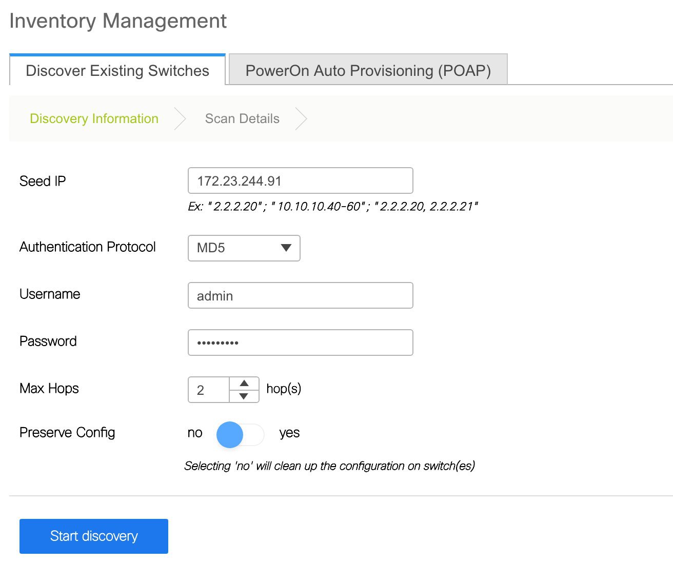
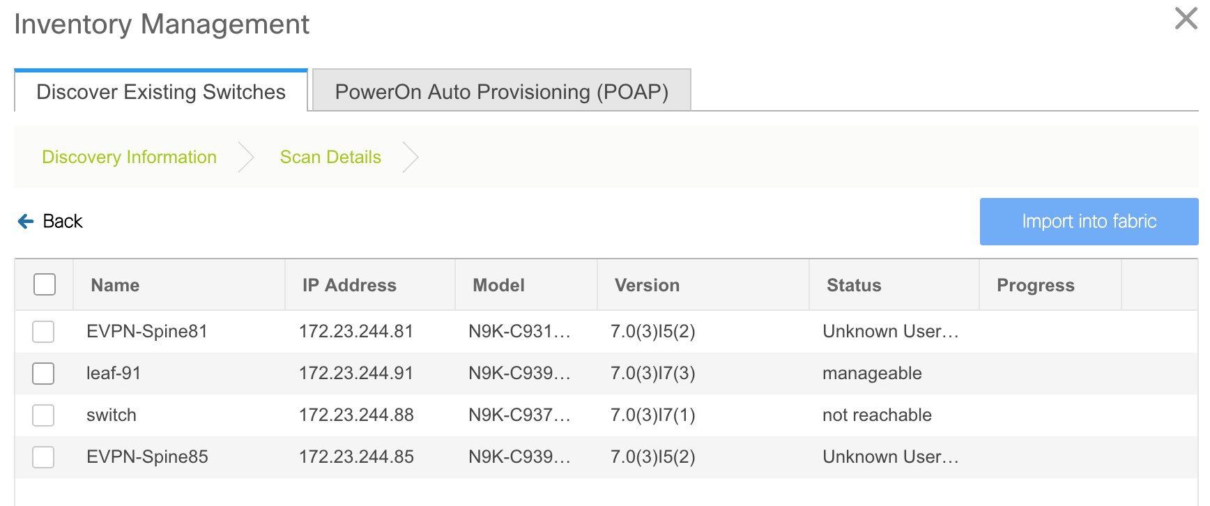
Click the Add Switches option from the Actions panel to add switches to the fabric. The Inventory Management screen comes up. The screen contains two tabs, one for discovering existing switches and the other for discovering new switches. Both options are explained.
Discovering Existing Switches
-
Use the Discover Existing Switches tab to add an existing switch. In this case, a switch with known credentials is added to the Standalone fabric. The IP address (Seed IP), administrator username, and password (Username and Password fields) of the switch are keyed in.
-
Click Start discovery. The Scan Details section comes up shortly. Since the Max Hops field was populated with 2, the switch with the specified IP address (leaf-91) and switches two hops from it are populated in the Scan Details section.
-
Select the check box next to the concerned switch and click Import into fabric.
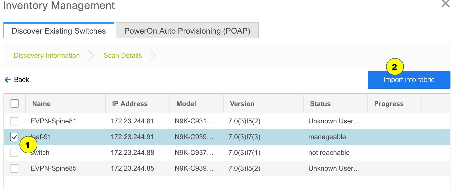
This example describes the discovery of one switch. You can discover multiple switches at the same time. The switches must be properly cabled and connected to the DCNM server and the switch status must be manageable.
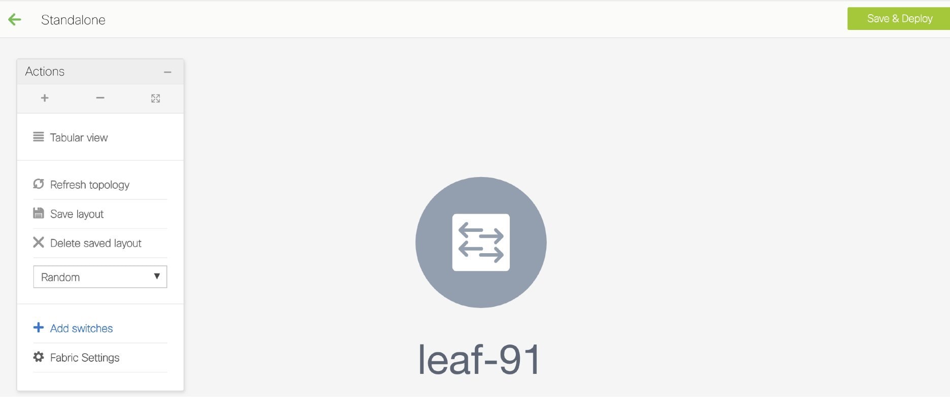
The switch discovery process is initiated. The Progress column displays the progress. After DCNM discovers the switch, the screen closes and the Standalone fabric screen comes up again. The switch icon can be seen at the center of the fabric page.
-
Click Refresh topology to view the latest topology view.
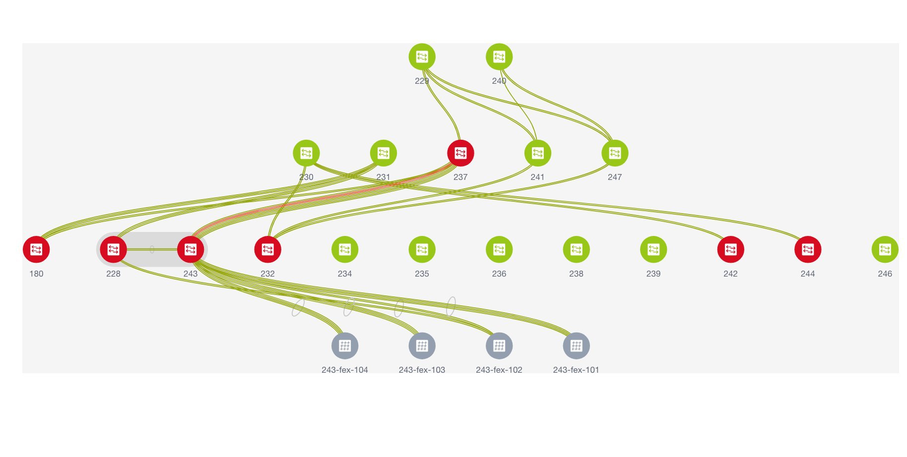
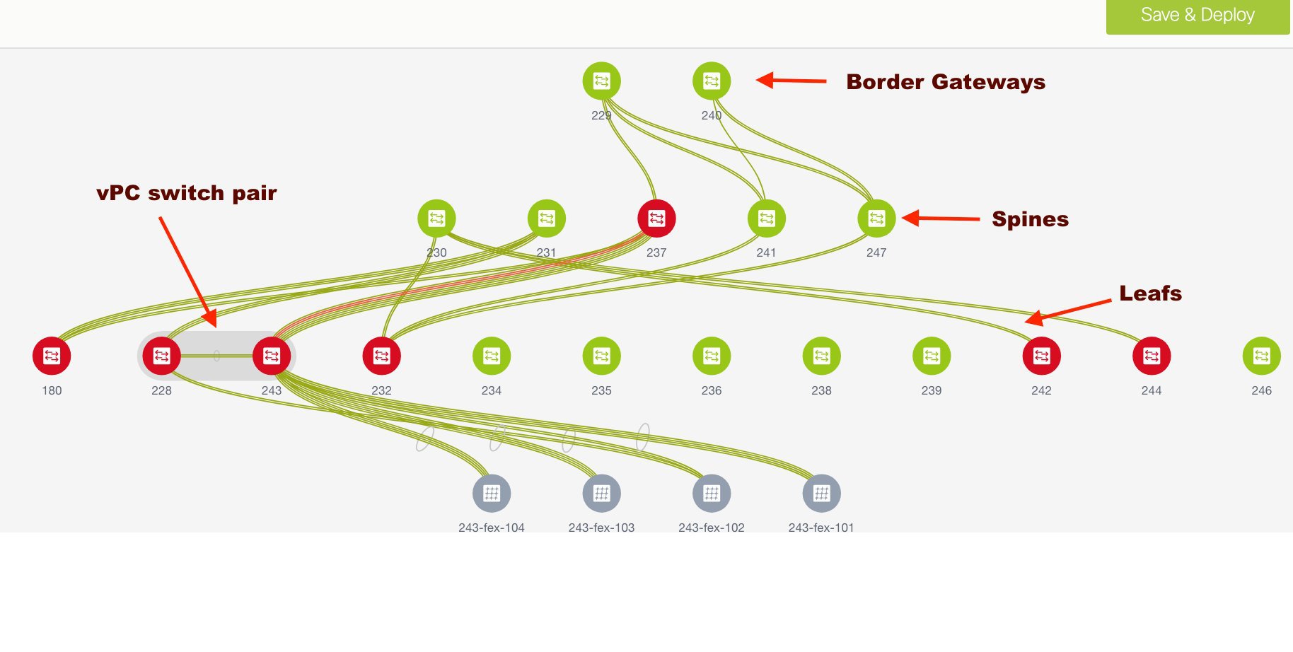
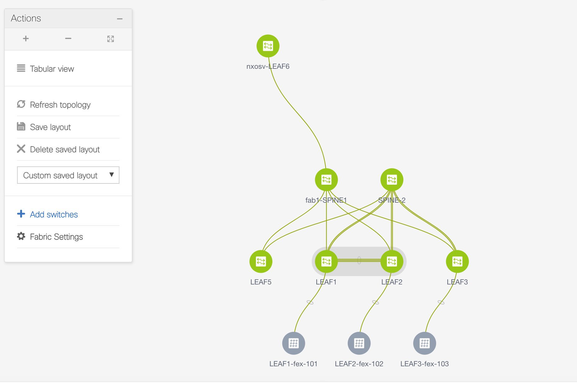
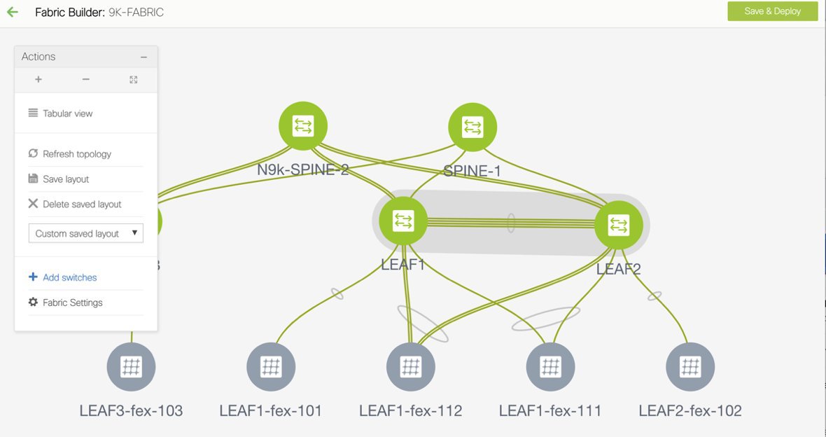
When more switches are added and roles assigned to them (which is explained in the next point), the fabric topology looks like the following image:
-
After discovering the switches, assign the fabric role to each switch. Since each switch is assigned the leaf role by default, assign the Border Gateway, Border (for a border leaf switch), and Spine roles. Right click the switch, and use the Set role option to set the appropriate role.
The topology automatically gets aligned as per role assignment, with the leaf switches at the bottom, the spine switches connected on top of them, and the BGW at the top.
Note
To connect fabrics using the EVPN Multi-Site feature, you must change the role of the designated BGW to Border Gateway. To connect fabrics using the VRF Lite feature, you must change the role of the border leaf switch to Border. If you want to deploy VRF Lite and EVPN Multi-Site features in a fabric, you must set the device role to Border Gateway and provision VRF Lite and Multi-Site features. If you do not update border device roles correctly at this stage, then you will have to remove the device from the fabric and discover it again through DNCM using the POAP bootstrap option and reprovision the configurations for the device.
Assign vPC switch role - To designate a pair of switches as a vPC switch pair, right-click the switch and choose the vPC peer switch from the list of switches.
AAA server password - During fabric creation, if you have entered AAA server information (in the Manageability tab), you must update the AAA server password on each switch. Else, switch discovery fails.
-
Click Save & Deploy at the top right part of the screen. The template and interface configurations form the underlay network configuration provisioning on the switches.
Also, freeform CLIs that were entered earlier are deployed.
Configuration Compliance - If the provisioned configurations and switch configurations do not match, then the switch icon turns red, indicating an out of sync status. For example, if you enable a function on the switch manually through a CLI, then it results in a configuration mismatch.
To ensure that the configurations that are provisioned from DCNM to the switch are accurate and detect any deviation from the intended configuration, DCNM recognizes and reports configuration deviation, and provides remediation configuration. Configuration compliance is supported for the fabric underlay and overlay deployments for Cisco Nexus 9000 Series switches.
-
When you click Save & Deploy, the Configuration Deployment Status section comes up.
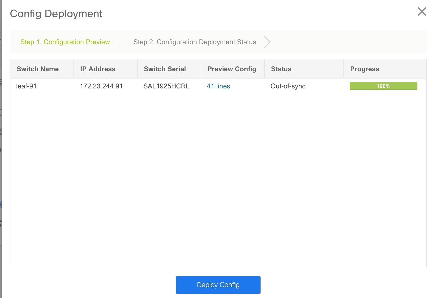
If the status is Out-of-sync, it suggests a compliance issue. Click the Preview Config column entry (updated with a specific number of lines). The Config Preview screen comes up.
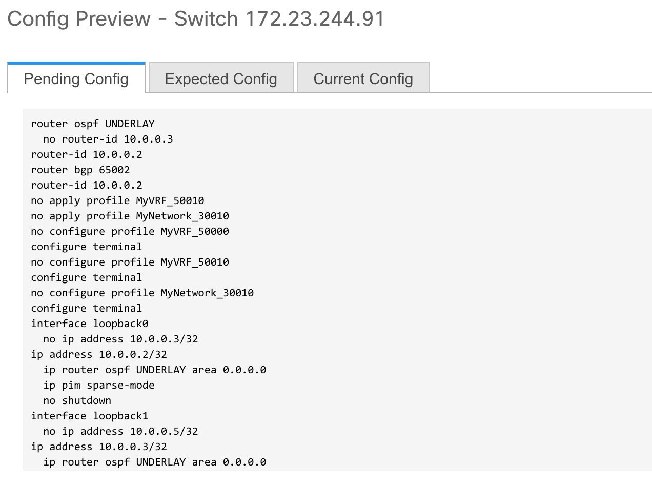
The Pending Config tab displays the pending configurations for successful deployment. The other tabs display the expected and configured configurations.
-
Close the screen. In the Configuration Deployment screen, click Deploy Config at the bottom part of the screen to initiate pending configuration onto the switch. The Status column displays FAILED or SUCCESS state. For a FAILED status, investigate the reason for failure to address the issue.
After correct provisioning and successful configuration compliance, close the screen. The switch icon colour turns to green, indicating successful configuration.
You can right click the switch icon and update switch related settings, as displayed in the image.
You can use Save & Deploy for single and multiple switches. Add switches and then click Save & Deploy to ensure configuration compliance. Whether discovering multiple switches at once or one by one, as a best practice, use Save & Deploy and not the Deploy Config option (accessible after right-clicking the switch icon).
When a leaf switch boots up after a switch reload or RMA operation, DCNM provisions configurations for the switch and FEX devices connected to it. Occasionally, FEX connectivity comes up after DCNM provisions FEX (host interface) configurations, resulting in a configuration mismatch. To resolve the mismatch, click Save & Deploy again in the fabric topology screen.
An example of the Deploy Config option usage is for switch-level freeform configurations. Refer the Freeform Configurations on Fabric Switches topic for details.
The Configuration Compliance function and principles are applicable for discovering existing and new switches. New switch discovery in DCNM (through a simplified POAP process) is explained next.
Discovering New Switches
-
Power on the new switch after ensuring that it is cabled to the DCNM server. Boot the Cisco NX-OS and setup switch credentials.
-
Execute the write erase and reload commands on the switch.
Click Yes to both the CLI commands that prompt you to choose Yes or No.
-
Set the boot variable to the image that you want to POAP. DCNM uses this image to POAP. Also, DCNM injects an information script into the switch to collect the device onboarding information.
-
In the DCNM GUI, go to the Standalone fabric (Click Control > Fabric Builder and click the fabric Standalone). The fabric topology is displayed.
Note
If you want to POAP with DHCP, make sure that DHCP is enabled on the fabric settings. Click Fabric Settings and edit the DHCP information in the Bootstrap tab.
-
Go to the fabric topology screen and click the Add switches option from the Actions panel. The Inventory Management screen comes up.
-
Click the POAP tab.
In an earlier step, the reload command was executed on the switch. When the switch restarts to reboot, DCNM retrieves the serial number, model number, and version from the switch and displays them on the Inventory Management along screen. Also, an option to add the IP address, hostname, and password are made available. If the switch information is not retrieved, refresh the screen.
Note
At the top left part of the screen, export and import options are provided to export and import the .csv file that contains the switch information.
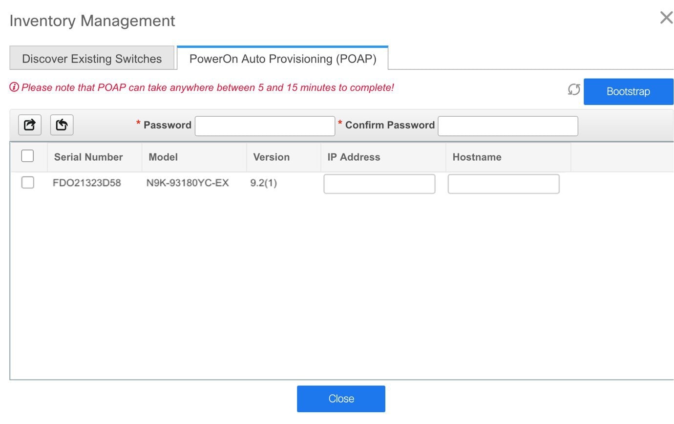
Select the checkbox next to the switch, add switch credentials (such as the IP address, host name and password), and click Bootstrap at the top right part of the screen. The fabric builder topology page appears.
DCNM provisions the management IP address and other credentials to the switch. In this simplified POAP process, all ports are opened up.
-
Click Refresh Topology to get updated information. The added switch goes through the POAP cycle. Monitor and check the switch for POAP completion.
-
After the added switch completes POAP, the fabric builder topology page is refreshed with the added switch with some physical connections. However, the switch icon is in red color indicating that the fabric is Out-Of-Sync and you must click Save & Deploy on the fabric builder topology to deploy pending configurations (such as template and interface configurations) onto the switches.
Note
For any changes on the fabric that results in the out-of-sync, then you must deploy the changes. The process is the same as explained in the Discovering Existing Switches section.
During fabric creation, if you have entered AAA server information (in the Manageability tab), you must update the AAA server password on each switch. Else, switch discovery fails.
-
After the pending configurations are deployed, the Progress column displays 100% for all switches.
-
Click Close to return to the fabric builder topology.
-
Click Refresh Topology to view the update. All switches must be in green color indicating that they are functional.
-
The switch and the link are discovered in DCNM. Configurations are built based on various policies (such as fabric, topology, and switch generated policies). The switch image (and other required) configurations are enabled on the switch.
-
In the DCNM GUI, the discovered switches can be seen in the Standalone fabric topology. Up to this step, the POAP is completed with basic settings. All the interfaces are set to trunk ports. You must setup interfaces through the Control > Interfaces option for any additional configurations, but not limited to the following:
-
vPC pairing.
-
Breakout interfaces.
-
Port channels, and adding members to ports.
-
Note |
|
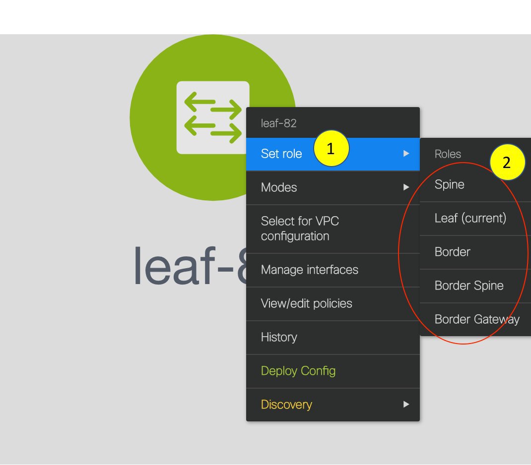
You can right-click the switch to view various options:
-
Set Role - Assign a role to the switch (Spine, Border Gateway, and so on).
Note
Changing of the switch role is allowed only before executing Save & Deploy.
-
Mode - Maintenance and Active/Operational modes.
-
Select for vPC Configuration - Select a switch for vPC and then select its peer.
-
Manage Interfaces - Deploy configurations on the switch interfaces.
-
View/Edit Policies - See switch policies and edit them as required.
-
History - View per switch deployment history.
-
Deploy Config - Deploy per switch configurations.
-
Discovery - You can use this option to update the credentials of the switch, reload the switch, rediscover the switch, and remove the switch from the fabric.
The new fabric is created, the fabric switches are discovered in DCNM, the underlay networks provisioned on those switches, and the configurations between DCNM and the switches are synced. The remaining tasks are:
-
Provision interface configurations such as vPCs, loopback interface, and subinterface configurations. [Interfaces topic].
-
Create overlay networks and VRFs and deploy them on the switches. [Networks and VRFs Creation and Deployment section].
Return Material Authorization (RMA)
This section describes how to replace a physical switch in a Fabric when using Cisco DCNM Easy Fabric mode.
Prerequisites
-
Fabric is assumed to be up and running, and minimal disruption is desired when replacing the switch. Also, the switch must be replaced with a switch of the same model (ASIC type) and physical port configuration.
-
To use the POAP RMA flow, you must configure the fabric for bootstrap (POAP).
-
To copy the FEX configurations for the RMA of switches which have FEX deployed, you may need to perform the Save and Deploy operation one or two times.
Guidelines and Limitations
-
The switch must be replaced with a switch of the same model (ASIC type) and physical port configuration. If not, the old switch must be removed and a new switch (replacement) added as a new switch into the fabric.
POAP RMA Flow
Procedure
| Step 1 |
Choose Control > Fabric Builder. |
| Step 2 |
Click the Fabric where you want to perform RMA. |
| Step 3 |
Move the device into maintenance mode. To move a device into maintenance mode, right-click on the device, and then choose Modes > Maintenance Mode. 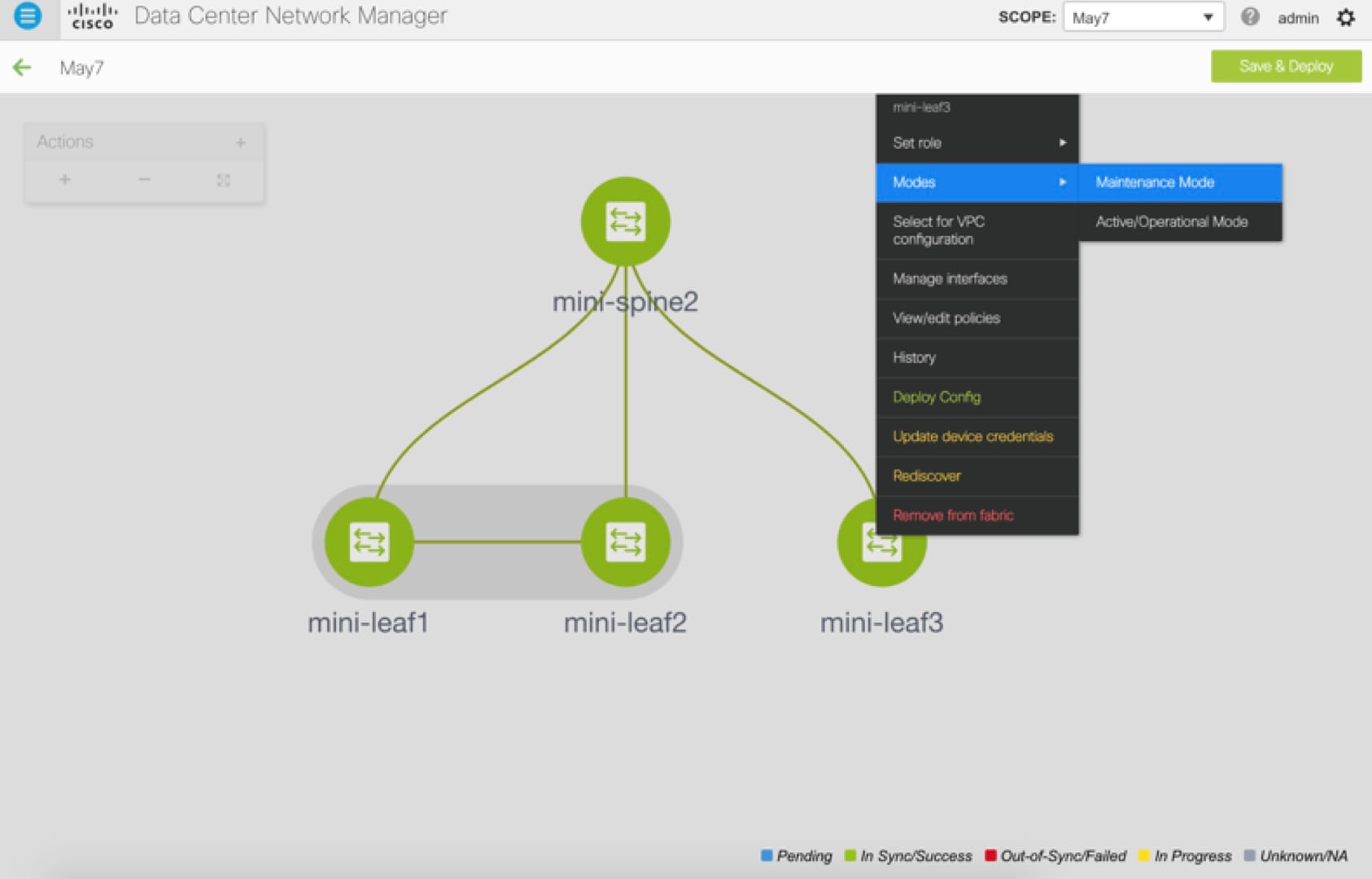 |
| Step 4 |
Physically replace the device in the network. Physical connections should be made in the same place on the replacement switch as they existed on the original switch. |
| Step 5 |
Provision RMA flow and select the replacement device. 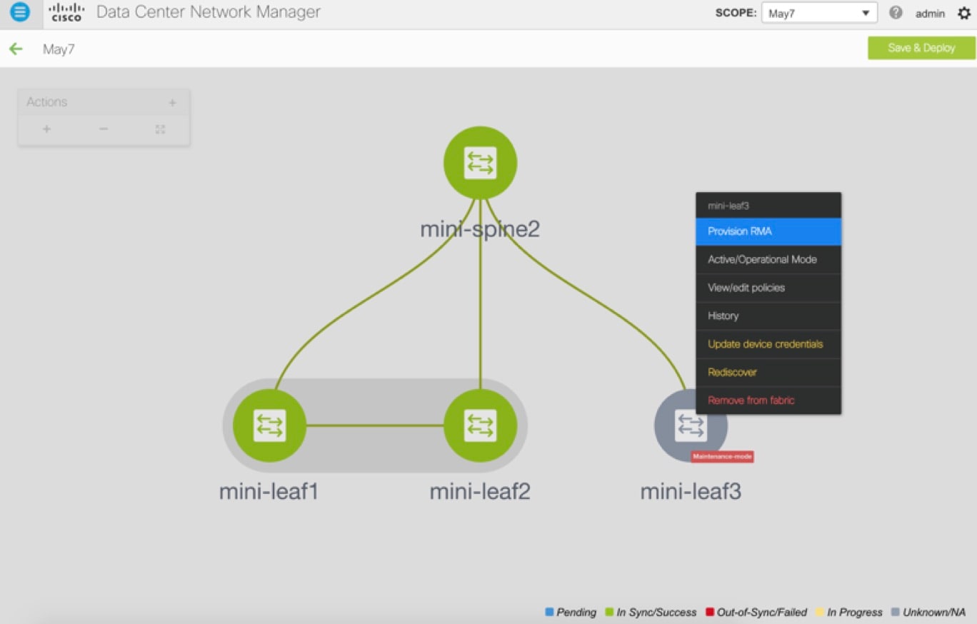 |
| Step 6 |
The Provision RMA UI will show the replacement device 5-10 minutes after it is powered on. 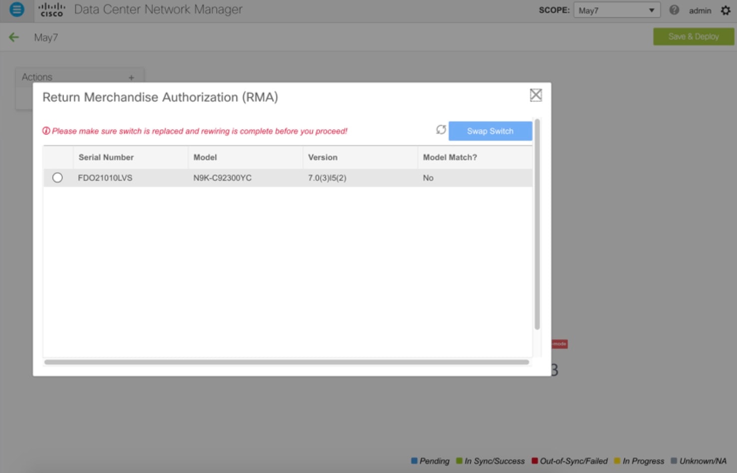 |
| Step 7 |
Select the correct replacement device and click Swap Switch. This begins POAP with the full “expected” configuration for that device. Total POAP time is generally around 10-15 minutes. 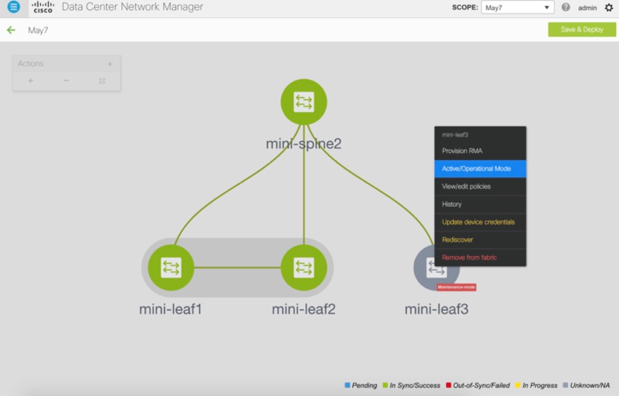 |
Manual RMA Flow
Use this flow when “Bootstrap” is not possible (or not desired), including cases that are IPv6 only for the initial Cisco DCNM 11.0(1) release.
Procedure
| Step 1 |
Place the device in maintenance mode (optional). 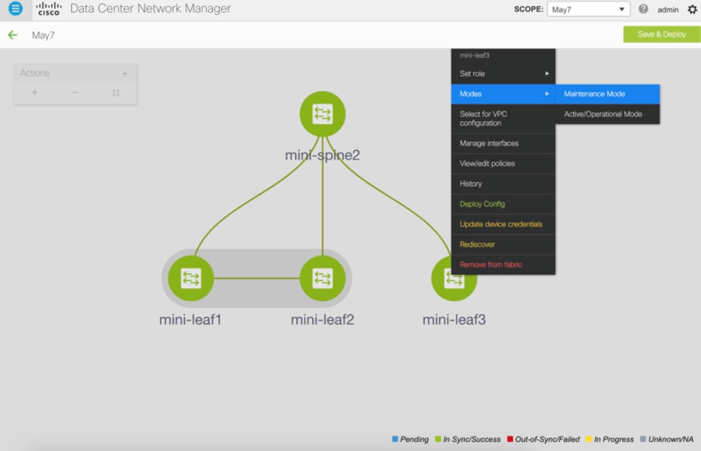 |
| Step 2 |
Physically replace the device in the network. |
| Step 3 |
Log in through Console and set the Management IP and credentials. |
| Step 4 |
The Cisco DCNM rediscovers the new device (or you can manually choose Discovery > Rediscover). |
| Step 5 |
Deploy the expected configuration using Deploy. 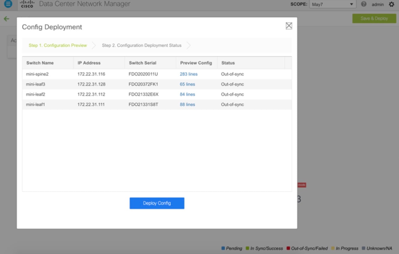 |
| Step 6 |
Depending on the configuration, if breakout ports or FEX ports are in use, you have to deploy again to completely restore the configuration. |
| Step 7 |
After a successful deployment, and the device is “In-Sync,” you must move the device back to Normal Mode. 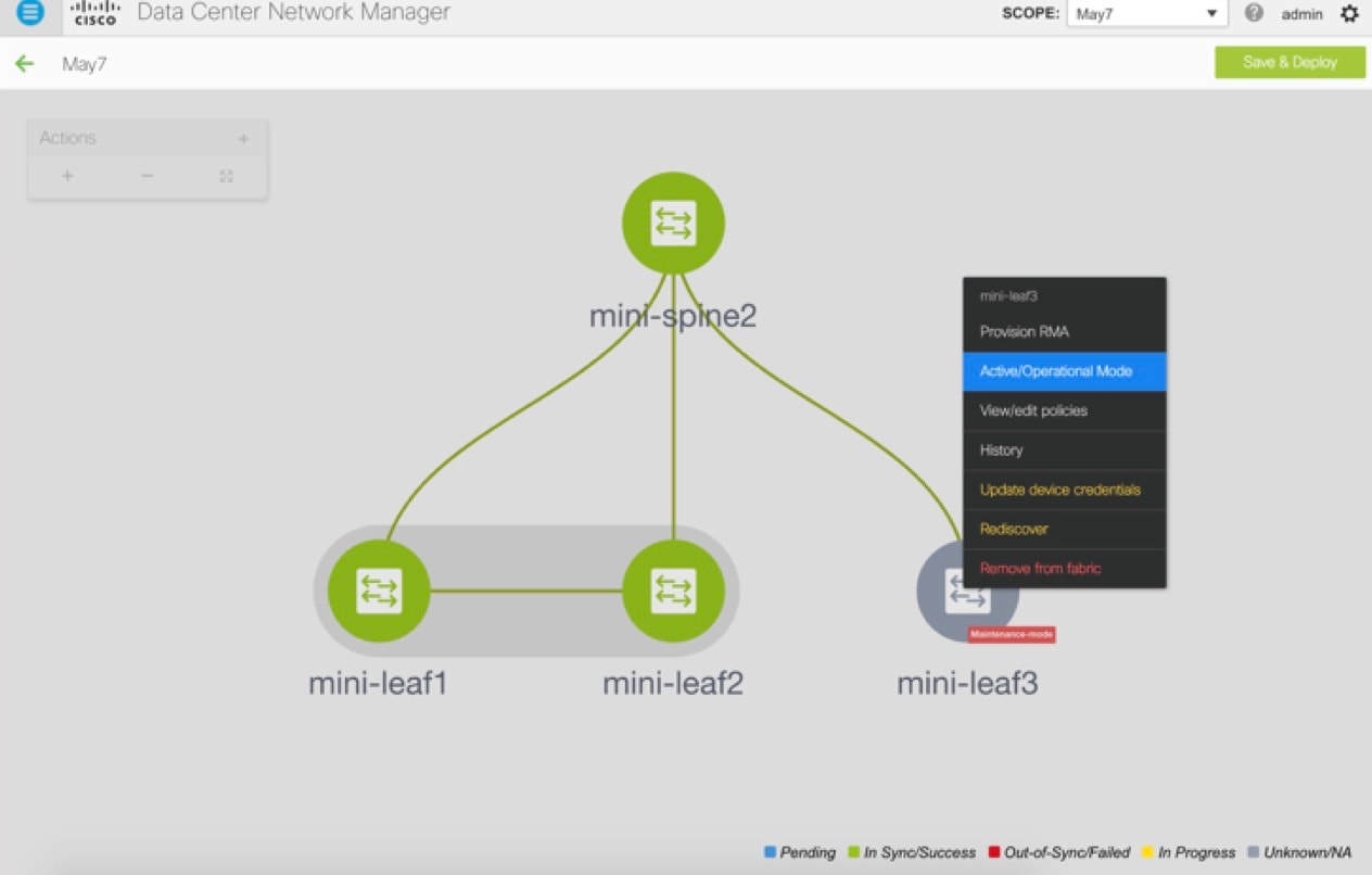 |
RMA for User with Local Authentication
Note |
This task is only applicable to non-POAP switches. |
Use the following steps to perform RMA for a user with local authentication:
Procedure
| Step 1 |
After the new switch comes online, SSH into the switch and reset the local user passwords with the cleartext password using the “username” command. Reset the local user passwords to resync the SNMP password. The password is stored in the configuration file in a nontransferable form. |
| Step 2 |
Wait for the RMA to complete. |
| Step 3 |
Update Cisco DCNM switch_snmp_user policy for the switch with the new SNMP MD5 key from the switch. |
Interfaces
The Interfaces option displays all the interfaces that are discovered for the switch, Virtual Port Channels (vPCs), and intended interfaces missing on the device.
You can use the following functions:
-
Create, deploy, view, edit and delete a port channel, vPC, Straight-through FEX, Active-Active FEX, loopback, and subinterface.
-
Create breakout and unbreakout ports.
-
Shut down and bring up interfaces.
-
Rediscover ports and view interface configuration history.
-
Apply host policies on interfaces and vPCs. For example, int_trunk_host_11_1, int_access_host_11_1, and so on.
-
View interface information such as its admin status, operation status, reason, policy, speed, MTU, mode, VLANs, IP/Prefix, VRF, port channel, and the neighbor of the interface.
Note
The Neighbor column provides details of connected switches that are discovered, intent links, and Virtual Machine Manager (VMM) connectivity. You can navigate to the Switch dashboard of the corresponding switch by clicking it. However, intent links and VMM links are not hyperlinked and you cannot navigate to the corresponding dashboard.
The Status column displays the following statuses of an interface:
-
Blue: Pending
-
Green: In Sync/Success
-
Red: Out-of-Sync/Failed
-
Yellow: In Progress
-
Grey: Unknown/NA
-
You can filter and view information for any of the given fields (such as Device Name). The following table describes the buttons that appear on this page.
Note |
|
|
Field |
Description |
|---|---|
|
Add |
Allows you to add a logical interface such as a port channel, vPC, Straight-through FEX, Active-Active FEX, loopback and subinterface. |
|
Breakout, Unbreakout |
Allows you to breakout an interface or unbreakout interfaces that are in breakout state. |
|
Edit |
Allows you to edit and change policies that are associated with an interface. |
|
Delete |
Allows you to delete a logical interface that is created from the Interfaces screen. An interface having a policy that is attached from an overlay and underlay cannot be deleted. |
|
No Shutdown |
Allows you to enable an interface (no shutdown or admin up). |
|
Shutdown |
Allows you to shut down the interface. |
|
Show |
Allows you to display the interface show commands. A show command requires show templates in the template library. |
|
Rediscover |
Allows you to rediscover or recalculate the compliance status on the selected interfaces. |
|
Interface History |
Allows you to display the interface deployment history details. |
|
Deploy |
Allows you to deploy or redeploy saved interface configurations. |
This section contains the following:
Adding Interfaces
Procedure
| Step 1 |
Choose Control > Interfaces. You see the Scope option at the top right part of the screen. If you want to view interfaces for a specific fabric, select the fabric window from the list. External Fabric: On interfaces belonging to an external fabric, you cannot perform any operation except the show and rediscovery operations. |
| Step 2 |
Click Add to add a logical interface. The Add Interface window appears. |
| Step 3 |
In the Type field, choose the type of the interface. For example, port channel, Straight-through FEX, Active-Active FEX, vPC, loopback, and subinterface.
|
| Step 4 |
In the Select a Device field, choose the device. In the case of vPC or Active to Active FEX, select the vPC switch pair. |
| Step 5 |
In the Number field, on selection of Interface Type and device or vPC pair, this field is automatically populated from the Resource Manager. You can override this value. The new value is used only if it is available in the Resource Manager pool. Else, it results in an error. |
| Step 6 |
In the Policy field, you can select the policy to be applied on an interface. The field only lists the Interface Python Policy with tag interface_edit_policy and filtered based on the interface type. You must not create a _upg interface policy. For example, you should not create a policy using the vpc_trunk_host_upg, port_channel_aa_fex_upg, port_channel_trunk_host_upg, and trunk_host_upg options. |
| Step 7 |
Click Save to save the configurations. Only saved configurations are pushed to the device. While adding the interface, you can save the configuration only once. Successive saves results in the Resource could not be allocated error. Once saved, you can change the configurations by editing the interface. |
| Step 8 |
(Optional) Click the Preview option to preview the configurations to be deployed. |
| Step 9 |
Click Deploy to deploy the specified logical interface. The newly added interface appears in the screen. Breakout or Unbreakout: You can break out and unbreak out an interface by using the breakout option at the top left part of the screen. |
Editing Interfaces
To edit the interfaces from the Cisco DCNM Web UI, perform the following steps:
Note |
You can edit the interface if it does not have an overlay or underlay policy attached. The Edit Interface allows you to change the policy and add or remove an interface from a port channel or vPC. |
Procedure
| Step 1 |
Choose Control > Interfaces. You can break out and unbreak out an interface by using the breakout option at the top left part of the screen. |
| Step 2 |
Select the interface check box to edit an interface or vPC. Select corresponding check boxes for editing multiple interfaces. You cannot edit multiple port channels and vPC. You cannot edit interfaces of different types at the same time. |
| Step 3 |
Click Edit to edit an interface. The variables that are shown in the Edit Configuration window are based on the template and its policy. Select the appropriate policy. Preview the policy, save it and deploy the same. This window lists only Interface Python Policy with the tag interface_edit_policy and filtered based on the interface type. In a vPC setup, the two switches are in the order the switch names are displayed in the edit window. For example, if Switch Name is displayed as LEAF1:LEAF2, then Leaf1 is peer switch one and Leaf2 is peer switch two. |
Deleting Interfaces
To delete the interfaces from the Cisco DCNM Web UI, perform the following steps:
Note |
This option allows you to delete only logical ports, port channels, and vPCs. You can delete the interface if it does not have overlay or underlay policy attached. When a port channel or vPC is removed, the corresponding member ports get the default policy associated. The Default Policy can be configured in server.properties file. |
Procedure
| Step 1 |
Choose Control > Interfaces. |
| Step 2 |
Select the interfaces. |
| Step 3 |
Click Delete to delete the interface. |
Shutting Down and Bringing Up Interfaces
Procedure
| Step 1 |
Choose Control > Interfaces. |
| Step 2 |
Select the interfaces that you want to shut down or bring up. |
| Step 3 |
Click Shutdown to disable the selected interfaces. For example, you may want to isolate a host from the network or a host that is not active in the network. |
| Step 4 |
Click No Shutdown to bring up the selected interfaces. |
Viewing Interface Configuration
Procedure
| Step 1 |
Choose Control > Interfaces. Select the interface whose configurations you want to view. |
| Step 2 |
In the Interface Show Commands window, select the action from the Show drop-down box and click Execute. The interface configurations are displayed in the Output section, at the right of the screen. For Show commands, you must have corresponding show templates that are defined in the Template Library. |
Rediscovering Interfaces
Procedure
| Step 1 |
Choose Control > Interfaces. |
| Step 2 |
Select the interfaces that you want to rediscover. |
| Step 3 |
Click Rediscover to rediscover the selected interfaces. For example, after you edit or enable an interface, you can rediscover the interface. |
Viewing Interface History
Procedure
| Step 1 |
Choose Control > Interfaces. |
| Step 2 |
Select the interface. |
| Step 3 |
Click Interface History to view the configuration history on the interface. |
| Step 4 |
Click Status to view each command that is configured for that configuration instance. |
Deploying Interface Configurations
Procedure
|
Choose Deploy to deploy and redeploy configurations that are saved for an interface. You can select multiple interfaces and deploy pending configurations. |
Networks and VRFs Creation and Deployment in a Standalone Fabric
The steps for overlay networks and VRFs provisioning are:
-
Create networks and VRFs for the fabric.
-
Deploy the networks and VRFs on the fabric switches.
Note |
The undeployment and deletion of overlay networks and VRFs are explained after the explanation of deployment. Finally, creation of external fabrics and fabric extensions from VXLAN to external fabrics are documented. |
The two steps are explained:
Create Networks for the Fabric
-
Click Control > Networks & VRFs (under Fabrics submenu). The LAN Fabric Provisioning page comes up.
-
Click Continue. The Select a Fabric page is displayed.
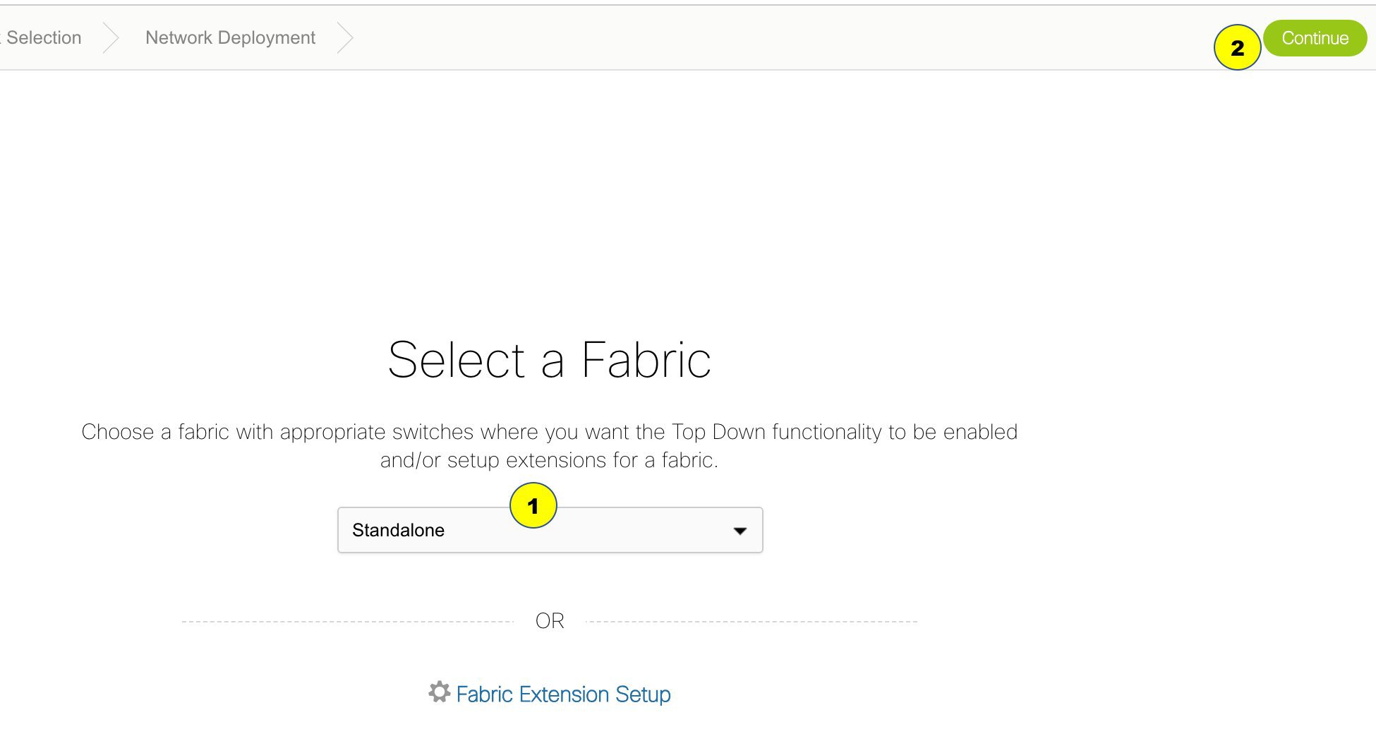
-
From the Select a Fabric drop-down list, select the fabric Standalone, and click Continue on the top right part of the screen. The Networks page is displayed. This page lists the networks that are created for the fabric. Initially, this page will not have any entries.
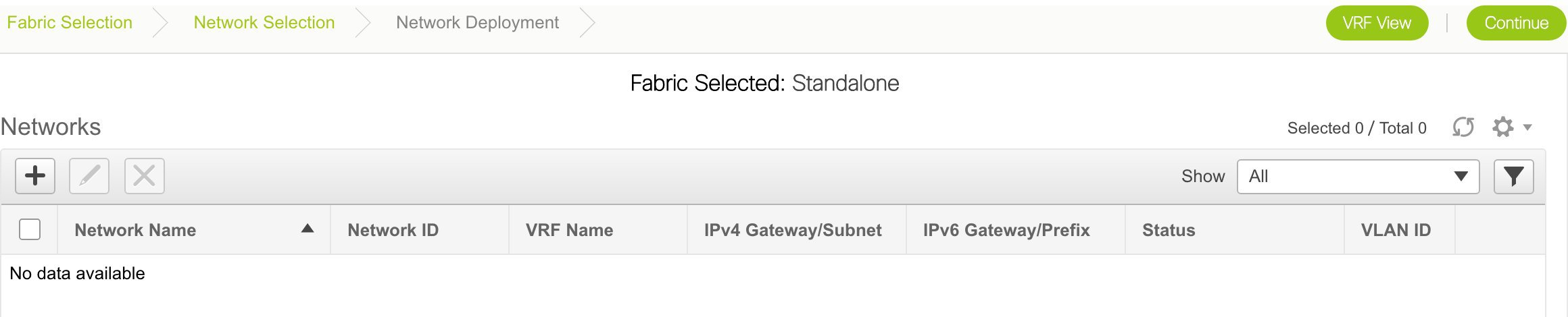
-
Click the + button at the top left part of the screen (under Networks) to add networks to the fabric. The Create Network screen comes up. Most of the fields are autopopulated.
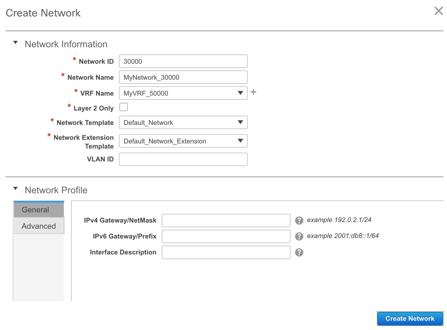
The fields in this screen are:
Network ID and Network Name: Specifies the Layer 2 VNI and name of the network. The network name should not contain any white spaces or special characters except underscore (_) and hyphen (-). The corresponding Layer 3 VNI (or VRF VNI) is generated along with VRF creation.
VRF Name: Allows you to select the Virtual Routing and Forwarding (VRF).
When no VRF is created, this field appears blank. If you want to create a new VRF, click the + button. The VRF name should not contain any white spaces or special characters except underscore (_), hyphen (-), and colon (:).
Layer 2 Only: Specifies whether the network is Layer 2 only.
Network Template: Allows you to select a network template, and is only applicable for leaf switches.
Network Extension Template: Allows you to extend this network to another fabric, based on the extension method that you select. The methods are VRF Lite, Multi Site, and so on. The template is applicable for border leaf switches and BGWs.
VLAN ID: Specifies the corresponding tenant VLAN ID for the network.
Network Profile section contains the General and Advanced tabs.
General tab
IPv4 Gateway/NetMask: Specifies the IPv4 address with subnet.
IPv6 Gateway/Prefix: Specifies the IPv6 address with subnet.
Specify the anycast gateway IP address for transporting the L3 traffic from a server belonging to MyNetwork_30000 and a server from another virtual network. By default the anycast gateway IP address is the same for MyNetwork_30000 on all switches of the fabric that have the presence of the network.
Interface Description: Specifies the description for the interface. This interface is a switch virtual interface (SVI).
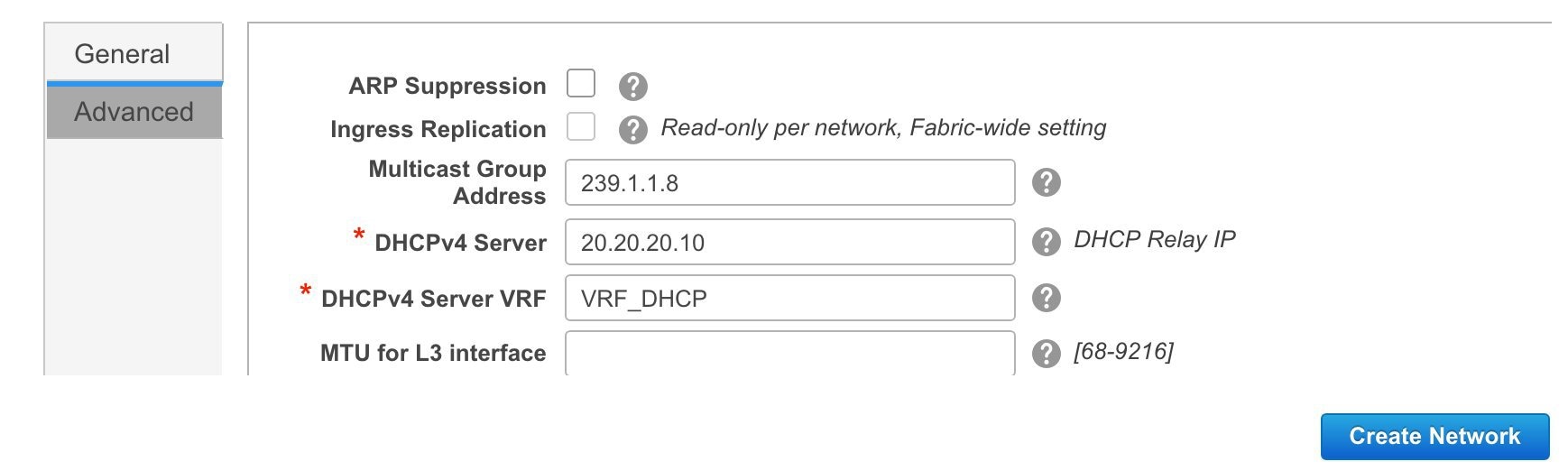
Advanced tab: Optionally, specify the advanced profile settings by clicking the Advanced tab:
-
ARP Suppression
-
Ingress Replication
Note
Ingress Replication is a read-only option in the Advanced tab. Changing the fabric setting updates the field.
-
Multicast Group Address
-
DHCPv4 Server
-
DHCPv4 Server VRF
-
MTU for the L3 interface
A sample of the Create Network page:

-
-
Click Create Network. A message appears at the bottom right part of the screen indicating that the network is created.
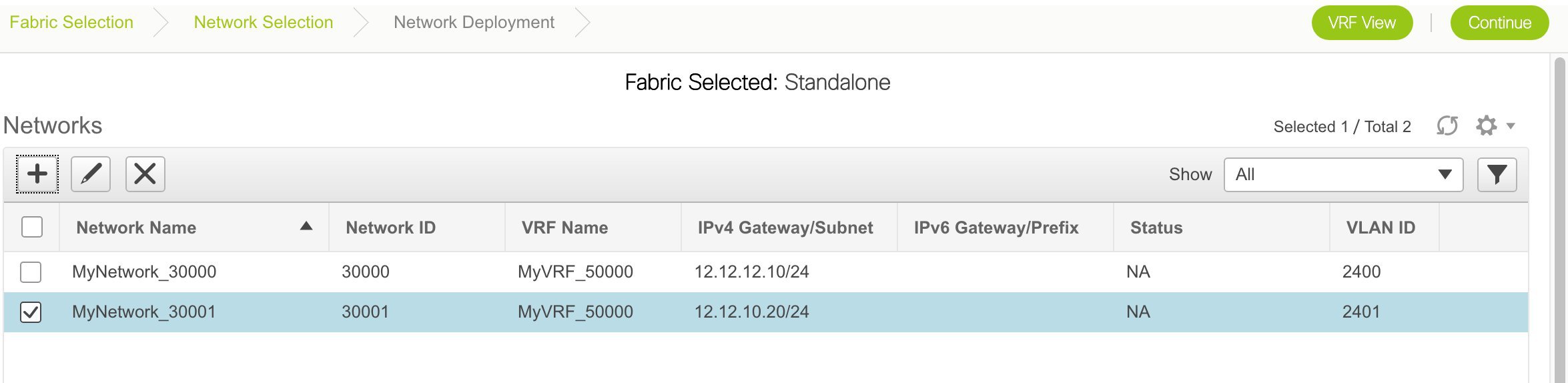
The new network appears on the Networks page that comes up.
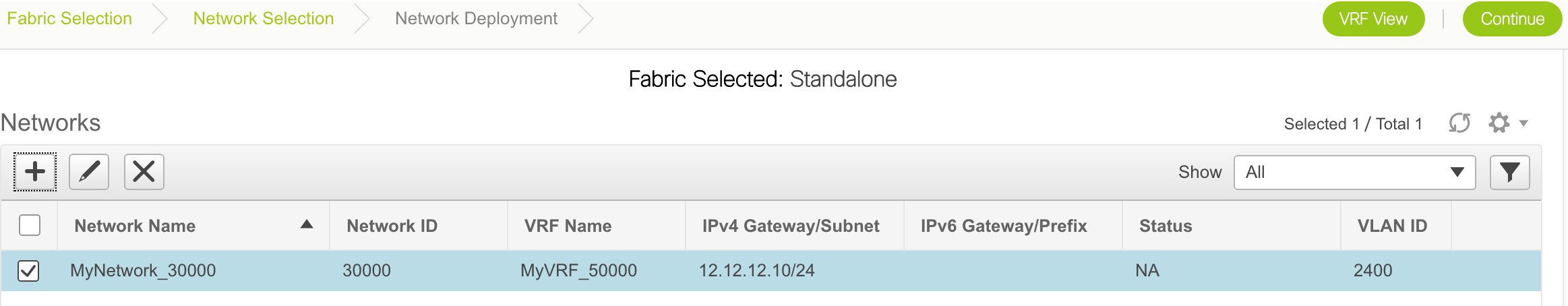
The Status is NA since the network is created but not yet deployed on the switches. Now that the network is created, you can create more networks if needed and deploy the networks on the devices in the fabric.
Create VRFs for a Standalone Fabric
-
From the Networks page, click the VRF View button at the top right part of the screen to create VRFs.
(If you have freshly logged in to DCNM, do the following:
Click Control > Networks & VRFs.
Click Continue in the LAN Fabric Provisioning page.
Choose the fabric (Standalone) from the drop-down list and click Continue to reach the Networks page.
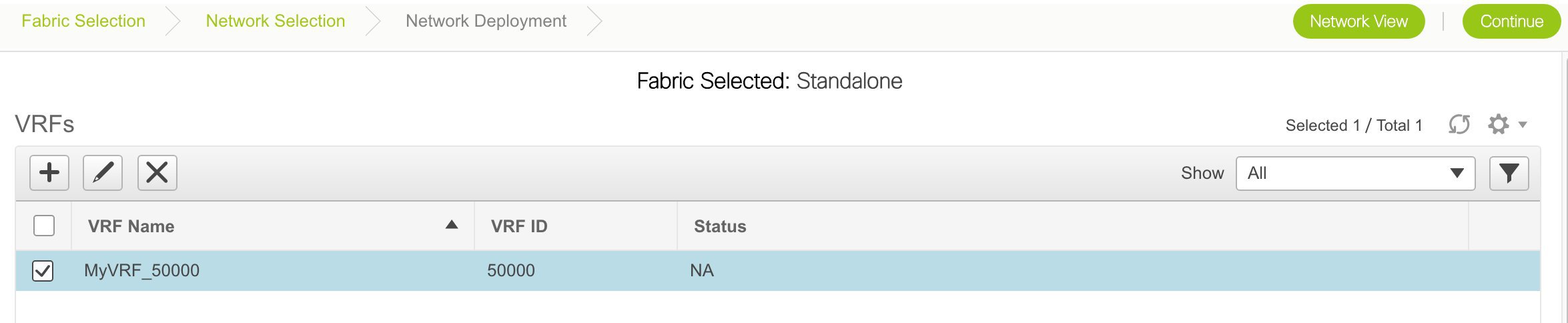
Click VRF View at the top right part of the Networks page).
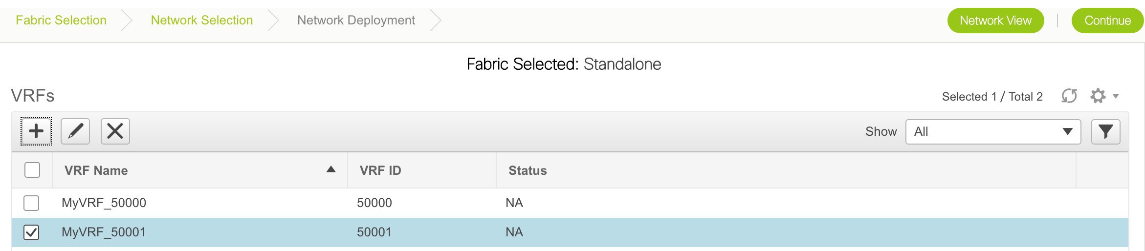
The VRFs page comes up. The page lists the list of VRFs created for the fabric. Initially, this page has no entries. One VRF is already created for this fabric. Let us create one more VRF.
-
Click the + button to add VRFs to the Standalone fabric. The Create VRF screen comes up. Most of the fields are autopopulated.
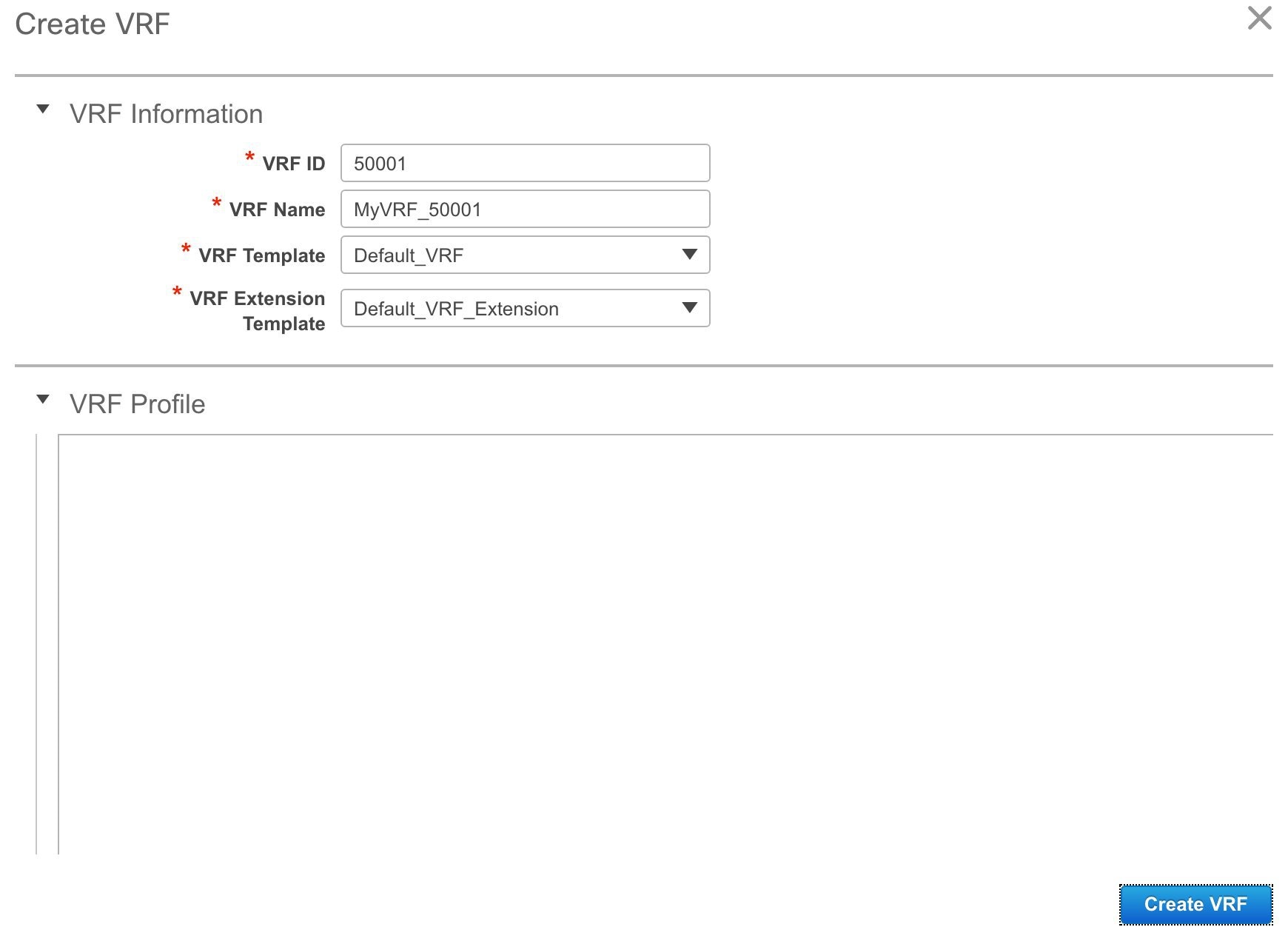
The fields in this screen are:
VRF ID and VRF Name: The ID and name of the VRF.
Note
For ease of use, the VRF creation option is also available while you create a network.
VRF Template: This template is applicable for VRF creation, and only applicable for leaf switches.
VRF Extension Template: The template is applicable when you extend the VRF to other fabrics, and is applicable for border leaf switches and border gateways.
-
Click Create VRF.
The MyVRF_50001 VRF is created and appears on the VRFs page.
Networks Deployment in the Standalone Fabric
Before you begin: Ensure that you have created networks for the fabric.
-
Go to the Select a Fabric page.
(To go to the Select a Fabric page do one of the following:
Click Fabric Selection at the top left part of the screen.
OR
From the main menu, click Control > Networks & VRFs and click Continue in the LAN Fabric Provisioning page).
-
Click Standalone from the drop-down list and click Continue on the top right part of the screen. The Networks page comes up.
The list of networks in the fabric are displayed on the page. The network deployment status is NA since the networks have not been deployed on any switch.
Note
You can edit or delete networks from this screen. You can only edit the Network Profile section at the bottom part of the screen.
-
Select networks that you want to deploy. In this case, select the checkboxes next to both the networks and click Continue at the top right part of the screen.
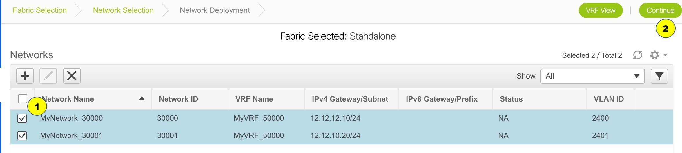
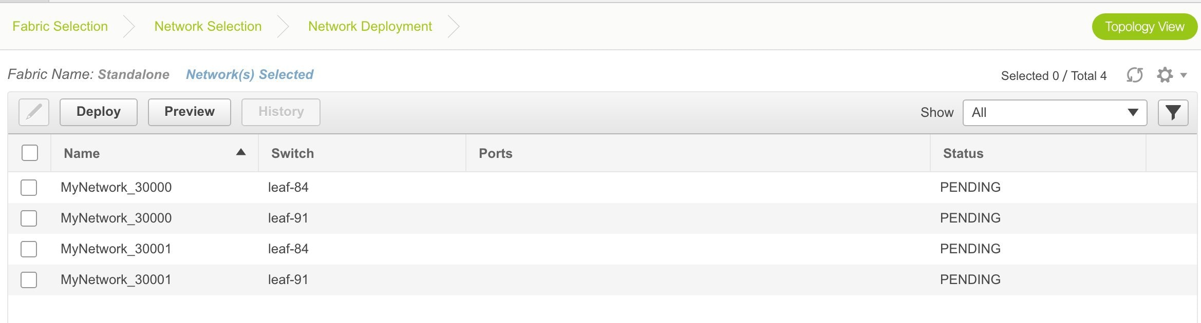
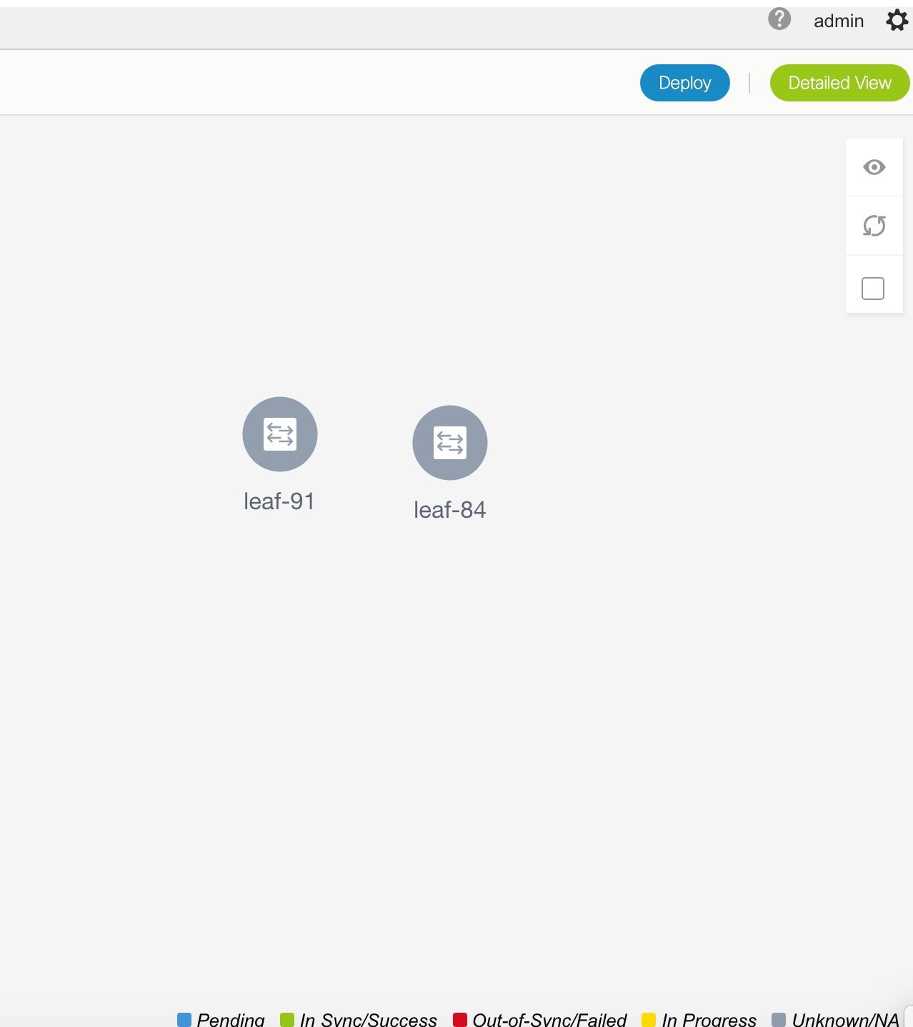
The Network Deployment page appears. On this page, you can see the network topology of the Standalone fabric.
You can deploy networks simultaneously on multiple switches. The selected devices should have the same role (Leaf, Border Gateway, and so on).
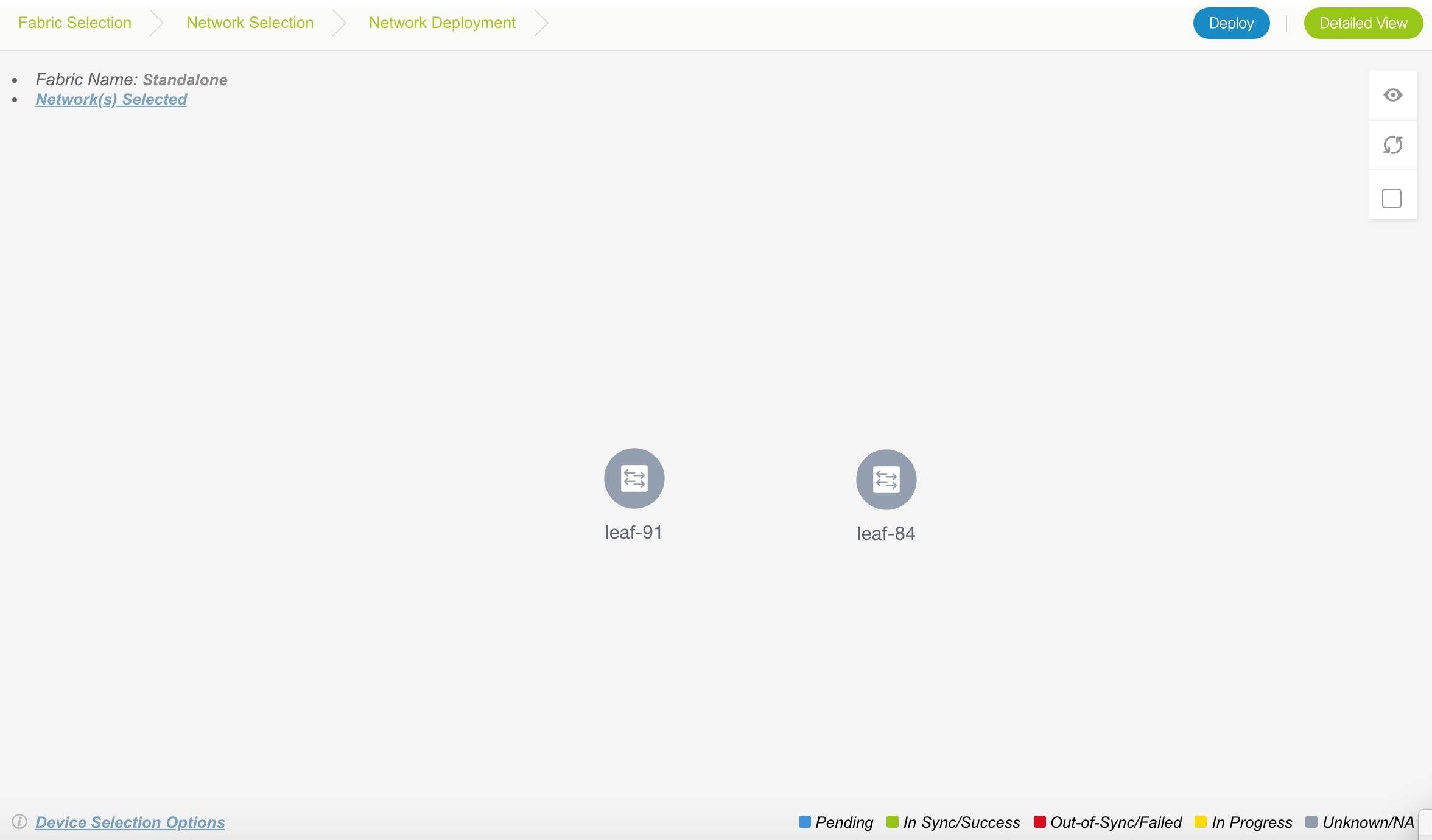
At the bottom right part of the screen, the color codes that represent different stages of deployment are displayed. The color of the switch icons changes accordingly (Blue for Pending state, yellow for In Progress when the provisioning is in progress, green when successfully deployed, and so on).
The overlay networks (/VRFs) provisioning status is context-specific. It is a combination of networks that you chose for provisioning and the relevant switches in the topology. In this example, it means that the networks MyNetwork_30000 and MyNetwork_30001 are yet to be deployed on any switch in this fabric.
You can move the topology around the screen by clicking the left mouse button on the screen and moving it in the direction you desire. You can enlarge or shrink the switch icons proportionately by moving the cursor roller. You can also use corresponding alternatives on the touchpad.
-
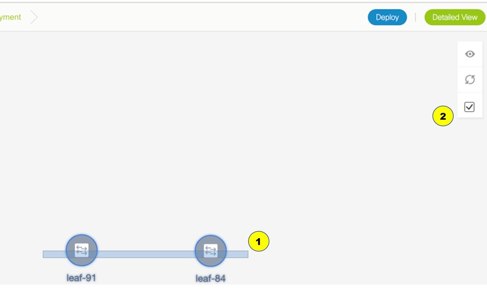
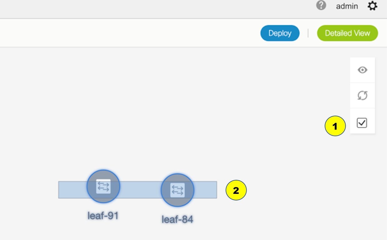
Double-click a switch (or use the Multi-Select option) to deploy the networks on it. For deployment of networks on multiple switches (like in this case, deploying MyNetwork_30000 and MyNetwork_30001 on leaf switches leaf-84 and leaf-91), do the following:
-
Click Multi-Select from the panel at the top right part of the screen. The topology freezes to a static state.
-
Drag the cursor across the switches.
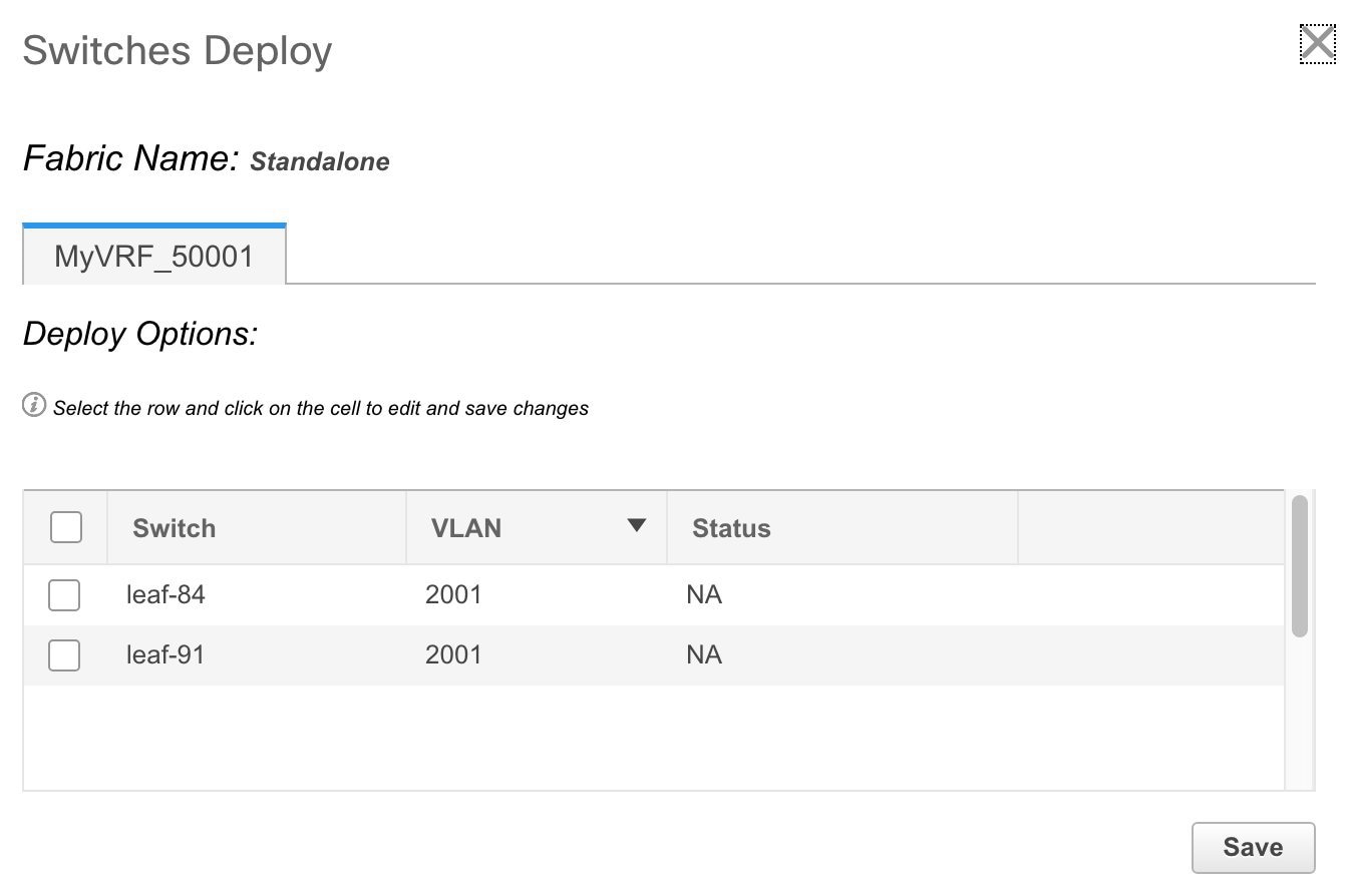
Immediately, the Switches Deploy screen (for networks) appears.
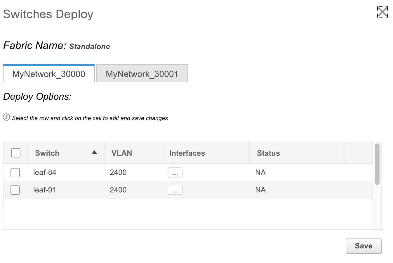
A tab represents each network (the first network, MyNetwork_30000, is displayed by default) that is being deployed. In each network tab, the switches are displayed. Each row represents a switch.
Click the checkbox next to the Switch column to select the switches. Both the switch check boxes are selected automatically. The network MyNetwork_30000 is ready to be provisioned on the switches leaf-84 and leaf-91.
Select the other network tab and make the same selections.
-
-
Click Save (at the bottom right part of your screen) to save the configurations.
Note
Addition and removal of interfaces are displayed in the Interfaces column of the Switches Deploy screen. Though the interface-related updates (like addition or removal of trunk ports) are provisioned on the switches, the correct configurations will not reflect in the preview screen. When you add or remove a trunk or access port, the preview shows the addition or removal of configurations for the interface under that network.
The topology screen comes up again. Click Refresh in the vertical panel at the top right part of the screen. The blue color on the switch icons indicates that the deployment is pending.
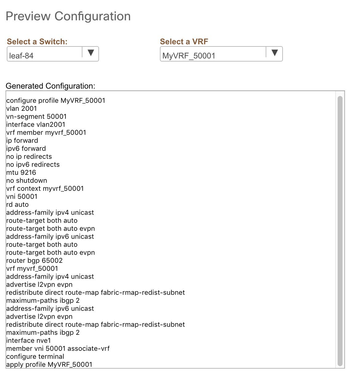
Preview the configurations by clicking Preview (the eye icon above the Multi-Select option). Since MyNetwork_30000 and MyNetwork_30001 are networks of VRF 50000, the configurations contain VRF configurations followed by the network configurations.
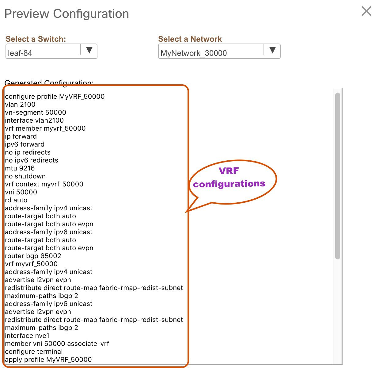
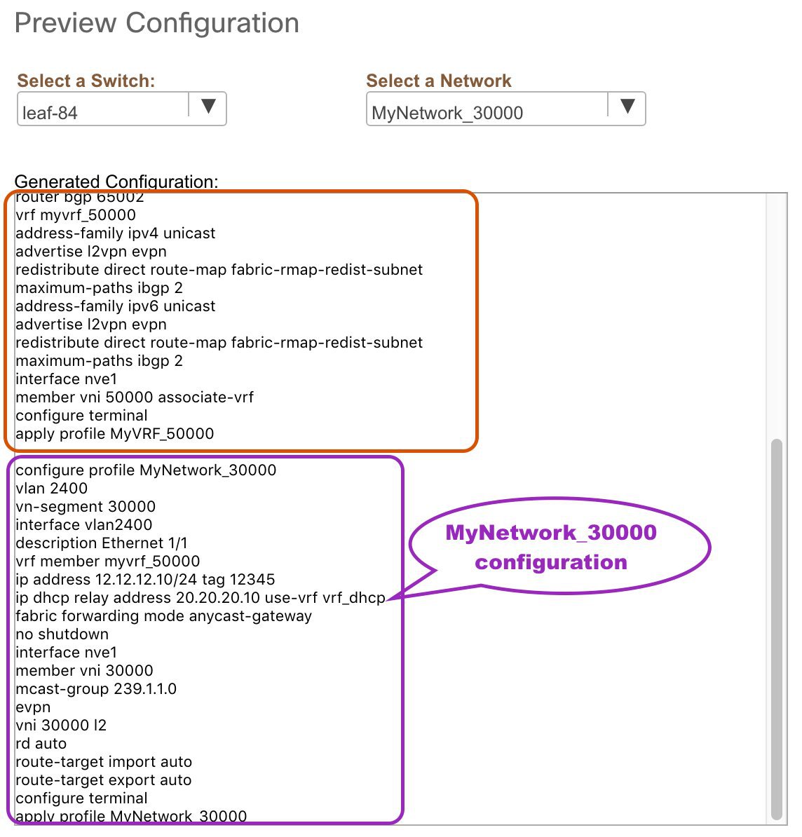
On the preview screen, you can select from the Select a switch and Select a network drop-down boxes at the top of the screen to view other network configurations.
After checking the configurations, close the screen. The Topology View appears.
-
Click Deploy on the top right part of the screen. The color of the switch icons changes to yellow and a message appears at the bottom right part of the screen indicating that the deployment is in progress. After the networks' deployment is complete, the color of the switch icons changes to green, indicating successful deployment.
Note
When you select multiple networks on the Topology View screen and proceed to the deployment screen, the switch color reflects the status of the first network in the selected list of networks. In this example, the switch color turns green when MyNetwork_30000 is provisioned on the switch. Go to the Networks page to view the individual status for all networks.
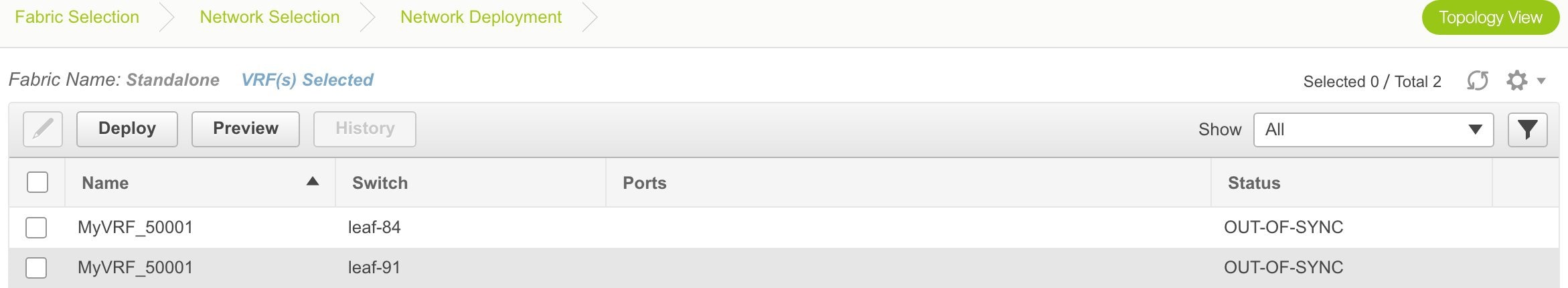
You can also use the Detailed View option to deploy networks and VRFs. Click Detailed View at the top right part of the screen. The Detailed View screen comes up.
Similar to the Topology View, you can preview configurations and deploy networks/VRFs (using the Preview and Deploy buttons). The Status column indicates that the deployment is pending. Use the Edit option to edit the networks.
In addition, the History button allows you to view the previous configuration instances and status.
On the Detailed View page, the network profile configuration history is displayed. If you have associated specific trunk interfaces to that network, then the interface configuration is displayed as a separate configuration instance.
Note |
When you upgrade from an earlier release, such as DCNM 10.4(2) to the DCNM 11.0(1) release, overlay networks and VRFs deployment history information from the earlier DCNM release is not retained. |
VRFs Deployment in the Standalone Fabric
-
From the Networks page, click VRF View at the top right part of the screen to deploy VRFs.
(If you have freshly logged in to DCNM, do the following:
Click Control > Networks & VRFs.
Click Continue in the LAN Fabric Provisioning page.
Choose Standalone from the drop-down list and click Continue to reach the Networks page.
Click VRF View at the top right part of the Networks page).
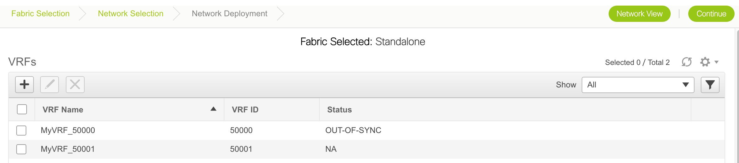
The VRFs page comes up. The list of VRFs created for the Standalone fabric are displayed in this screen.
-
Select VRFs (by selecting corresponding check boxes) that you want to deploy and click Continue at the top right part of the screen.
The VRF Deployment page appears. On this page, you can see the topology of the Standalone fabric.
The following example shows you how to deploy the MyVRF_50001 the VRF on the leaf switches leaf-84 and leaf-91. You can deploy VRFs simultaneously on multiple switches but of the same role (Leaf, Border Gateway, and so on).
At the bottom right part of the screen, the color codes that represent different stages of deployment are displayed. The color of the switch icons changes accordingly (Blue for Pending state, yellow for In Progress state when the provisioning is in progress, red for failure state, green when successfully deployed, and so on).
The overlay networks (or VRFs) provisioning status is context-specific. It is a combination of VRFs that you chose for provisioning and the relevant switches in the topology. In this example, it means that the VRF 50001 is yet to be deployed on any switch in this fabric.
You can move the topology around the screen by clicking the left mouse button on the screen and moving it in the direction you desire. You can enlarge or shrink the switch icons proportionately by moving the cursor roller. You can also use corresponding alternatives on the touchpad.
-
Double-click a switch to deploy the VRF on it. For deployment of VRFs on multiple switches (like in this case, deploying VRF 50001 on leaf switches leaf-84 and leaf-91), do the following:
-
Click the Multi-Select option from the panel at the top right part of the screen. This freezes the topology to a static state.
-
Drag the cursor across the switches.
Immediately, the Switches Deploy screen (for VRFs) appears.
A tab represents each VRF (the first selected VRF is displayed by default) that is being deployed. In each VRF tab, the switches are displayed. Each row represents a switch.
Click the checkbox next to the Switch column to select the switches. Both the switch check boxes are selected automatically. VRF 50001 is ready to be provisioned on the switches leaf-84 and leaf-91.
Select the other VRF tab and make the same selections.
-
-
Click Save (at the bottom right part of your screen) to save VRF configurations.
The topology screen comes up again. Click the Refresh button in the vertical panel at the top right part of the screen. The blue color on the switch icons indicates that the deployment is pending.
Preview the configurations by clicking the Preview button (the eye icon above the Multi-Select option).
After checking the configurations, close the screen. The Topology View screen appears.
-
Click the Deploy button on the top right part of the screen. The color of the switch icons changes to yellow and a message appears at the bottom right part of the screen indicating that the deployment is in progress. After the VRF deployment is complete, the color of the switch icons changes to green, indicating successful deployment.
You can also use the Detailed View button to deploy networks and VRFs.
Click Detailed View at the top right part of the screen. The Detailed View screen comes up.
Similar to the Topology View, you can preview configurations and deploy networks/VRFs (from the Preview and Deploy buttons). The Status column indicates that the deployment is pending. Use the Edit option to edit the options.
In addition, the History button allows you to view the previous configuration instances and status.
Note |
When you upgrade from an earlier release, such as DCNM 10.4(2) to the DCNM 11.0(1) release, overlay networks and VRFs deployment history information from the earlier DCNM release is not retained. |
Undeploying Networks
You can undeploy VRFs and networks from the Topology View page. The DCNM screen flow for undeployment is similar to the deployment process flow. Go to the Topology View page to undeploy networks:
-
Choose Control > Networks and VRFs.
-
In the Select a Fabric page, click Continue (at the top right part of the screen). The Networks page comes up.
-
Select the networks that you want to undeploy and click Continue. The Topology View page comes up.
-
On the Topology View page, select the Multi-Select button if you are undeploying the networks from multiple switches. The Switches Deploy screen comes up.
(For a single switch, double-click the switch and the Switches Deploy screen comes up).
-
In the Switches Deploy screen, the Status column for the deployed networks is displayed as DEPLOYED. Unselect the check boxes next to the switches, as needed. Ensure that you repeat this on all tabs since each tab represents a network.
-
Click Save (at the bottom right part of the screen) to initiate the undeployment of the networks. The Topology View comes up again.
Note
Alternatively, you can click the Detailed View button to undeploy networks.
-
Refresh the screen, preview configurations if needed and click Deploy to remove the network configurations on the switches. After the switch icons turn green, it indicates successful undeployment.
-
Go to the Networks page to verify if the networks have been undeployed.
Undeploying VRFs
You can undeploy VRFs and networks from the Topology View page. The DCNM screen flow for undeployment is similar to the deployment process flow.
-
Choose Control > Networks and VRFs.
-
In the Select a Fabric page, click Continue (at the top right part of the screen). The Networks page comes up.
-
Click the VRF View button (at the top right part of the screen) to go to the VRFs screen.
-
Select the VRFs that you want to undeploy and click Continue. The Topology View page comes up.
-
On the Topology View page, select the Multi-Select option if you are undeploying the VRFs from multiple switches. The Switches Deploy screen comes up.
(For a single switch, double-click the switch and the Switches Deploy screen comes up).
-
In the Switches Deploy screen, the Status column for the deployed VRFs is displayed as DEPLOYED. Unselect the check boxes next to the switches, as needed. Ensure that you repeat this on all tabs since each tab represents a VRF.
-
Click Save (at the bottom right part of the screen) to initiate the undeployment of the VRFs. The Topology View comes up again.
Note
Alternatively, you can click the Detailed View button to undeploy VRFs.
-
Refresh the screen, preview configurations if needed and click Deploy to remove the VRF configurations on the switches. After the switch icons turn green, it indicates successful undeployment.
-
Go to the VRFs page to verify if the networks have been undeployed.
Deleting Networks and VRFs in the MSD Fabric
If you want to delete networks and corresponding VRFs in the MSD fabric, follow this order:
-
Undeploy the networks, if not already done.
-
Delete the networks.
-
Undeploy the VRFs, if not already done.
-
Delete the VRFs.
Creating an External Fabric
You can create an external fabric in DCNM to depict a connection between the VXLAN and external fabrics in the DCNM GUI. After creating an external fabric, use the Add switches option to add switches to it. Some pointers:
-
An external fabric is a monitor-only mode fabric.
-
You can import, remove, and delete switches for an external fabric.
-
For Inter-Fabric Connection (IFC) cases, you can choose Cisco 9000, 7000 and 5600 Series switches as destination switches in the external fabric.
-
You can use non-existing switches as destination switches.
-
The template that supports an external fabric is External_Fabric.template.
-
On the Topology View screen, the VXLAN BGP EVPN and connected external fabrics can be viewed together.
Follow these steps to create an external fabric from Fabric Builder.
-
Click Control > Fabric Builder. The Fabric Builder page comes up.
-
Click the Create Fabric button. The Add Fabric screen comes up. The fields in this screen are:
Fabric Name - Enter the name of the external fabric.
Fabric Template - Choose External_Fabric.
When you choose the fabric template, the fabric creation screen for creating an external fabric comes up.
-
Enter the BGP AS number and click Save.
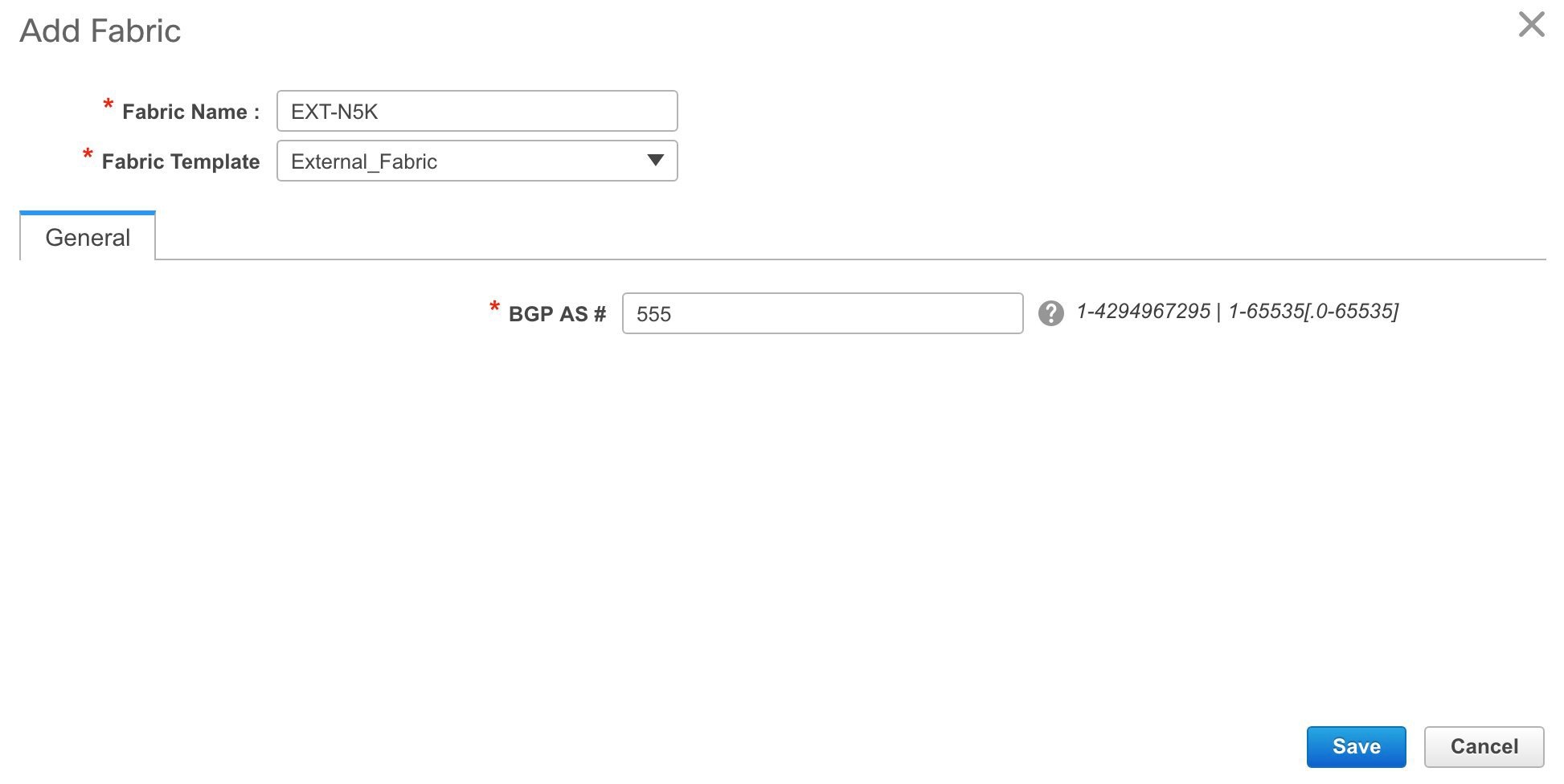
When you create an Inter-Fabric Connection from a VXLAN fabric to this external fabric, the BGP AS number is referenced as the external or neighbor fabric AS Number.
After the external fabric is created, the external fabric topology page comes up.
Note
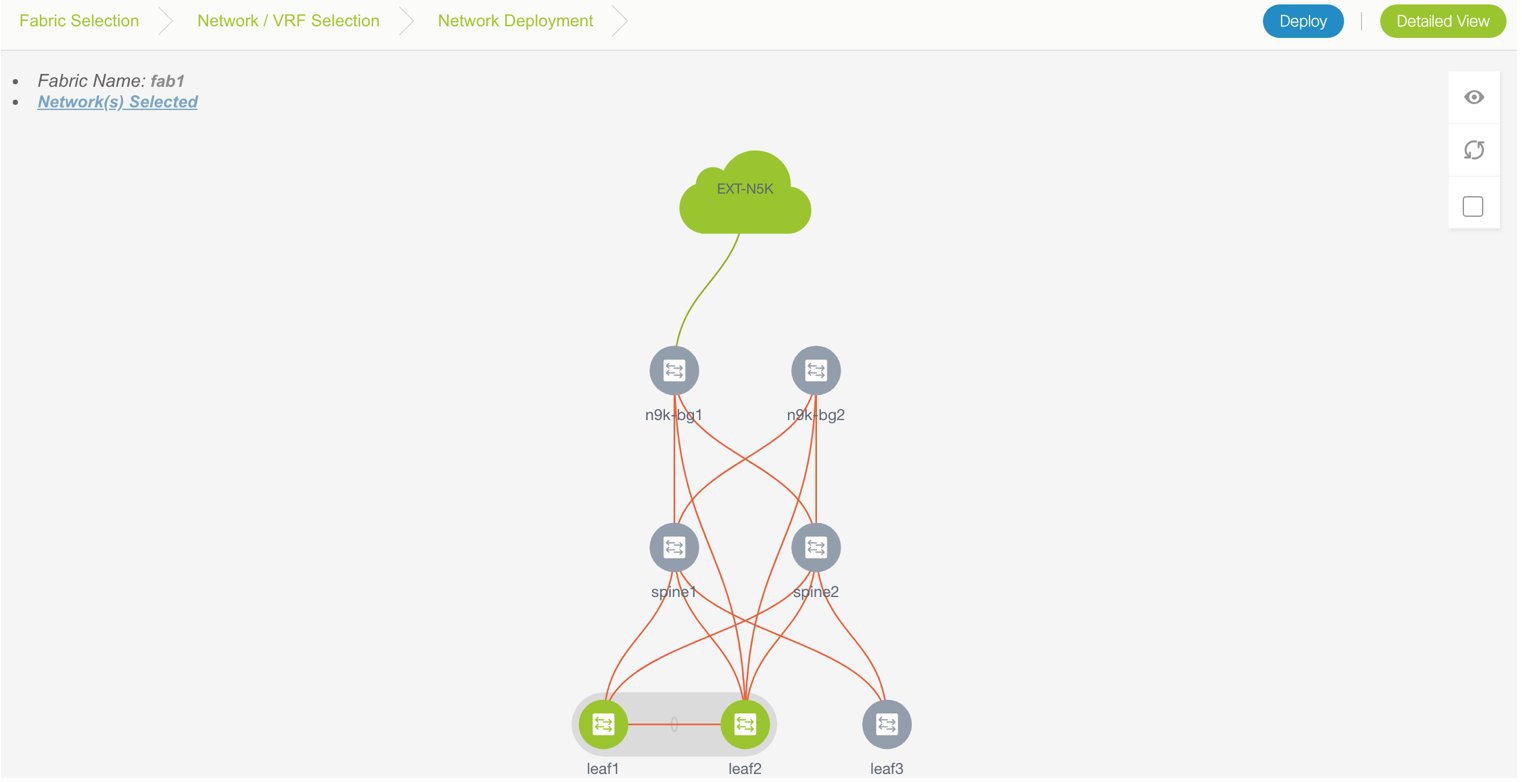
When you deploy networks or VRFs for the VXLAN fabric, the deployment page shows the VXLAN and external fabrics that are connected to each other.
A sample screenshot of the deployment page (Topology View screen) is shown. Note that individual devices in the external fabric are not shown and only a cloud icon with the fabric name is displayed.
Adding Fabric Extensions
Before You Begin - In the fabric topology, the border switches should be set with an appropriate role (for example, Border Leaf or Border Gateway). The subsequent procedure describes how the inter-fabric connections between the border devices in the selected fabric and the external devices are defined.
-
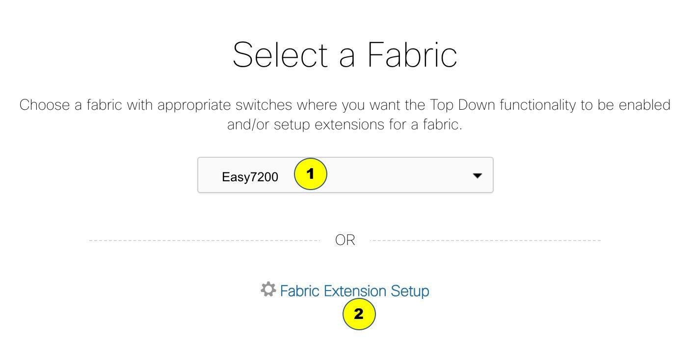
Click Control > Networks & VRFs (under Fabrics submenu). The LAN Fabric Provisioning page comes up.
-
Click Continue. The Select a Fabric page is displayed. From the Select a Fabric drop down box, select the source fabric from which you want to connect to the other fabric.
-
Click Fabric Extension Setup.
The Fabric Extension screen comes up.
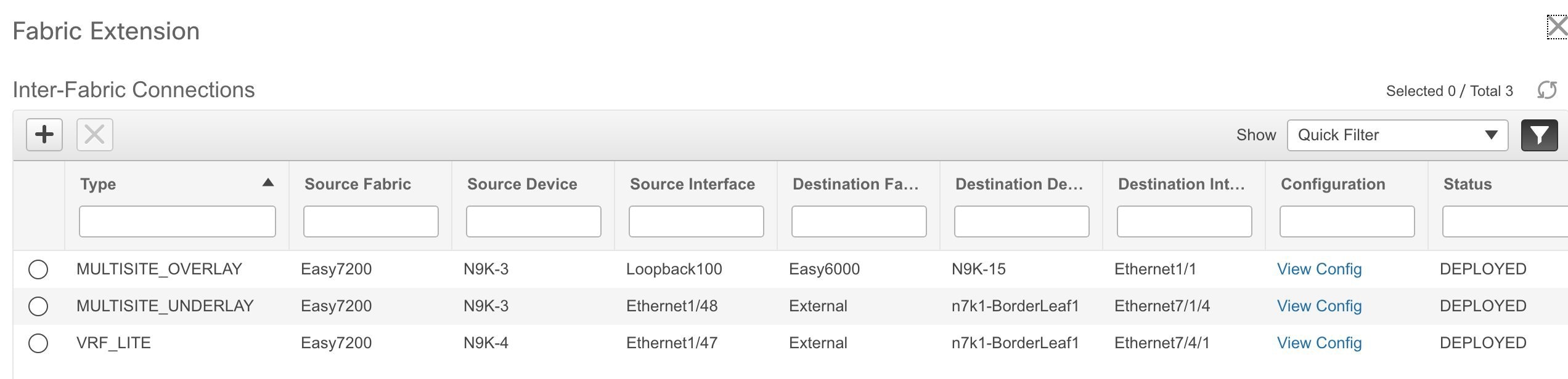
The Inter-Fabric Connections section lists previously created external connections. Each line represents a physical or logical connection between a border node in the selected fabric and an external device in some other fabric. For each connection, the source fabric, source device, source interface, destination fabric, destination device, and destination interface are listed along with the type of external connectivity. This section is empty the first time you add an external connection. Two primary types of external connectivity are supported, VRF Lite and EVPN Multi-Site.
VRF Lite (VRF_LITE) - For each VRF, an external BGP (eBGP) peering session needs to be set up between the border node and the external device. As part of the connection setup, the eBGP peering session is established from the border node in the default VRF along with additional global configuration of route-maps for IPv4/IPv6 cases.
EVPN Multi-Site - This requires setting up the Border Gateway base configuration for enabling the Multi-Site feature and the underlay peering to the external devices (MULTISITE_UNDERLAY). This is followed by establishing overlay peering from the border gateway to appropriate external devices, either Border Gateways in other fabrics or Route Servers (MULTISITE_OVERLAY). Both the underlay and overlay peering are established over eBGP. Recall that Border Gateways are special devices that allow clear control and data plane segregation from one site to another while allowing for policy enforcement points for any inter-fabric traffic. They allow the same data plane (VXLAN) and control plane (BGP EVPN) to be employed both for inter-fabric and intra-fabric traffic.
Note
If you extend the fabric through EVPN Multi-Site, you should first create an underlay extension (select MULTISITE_UNDERLAY in the Extension Type field) on the border gateway and then create overlay extensions (select MULTISITE_OVERLAY in the Extension Type field).
-
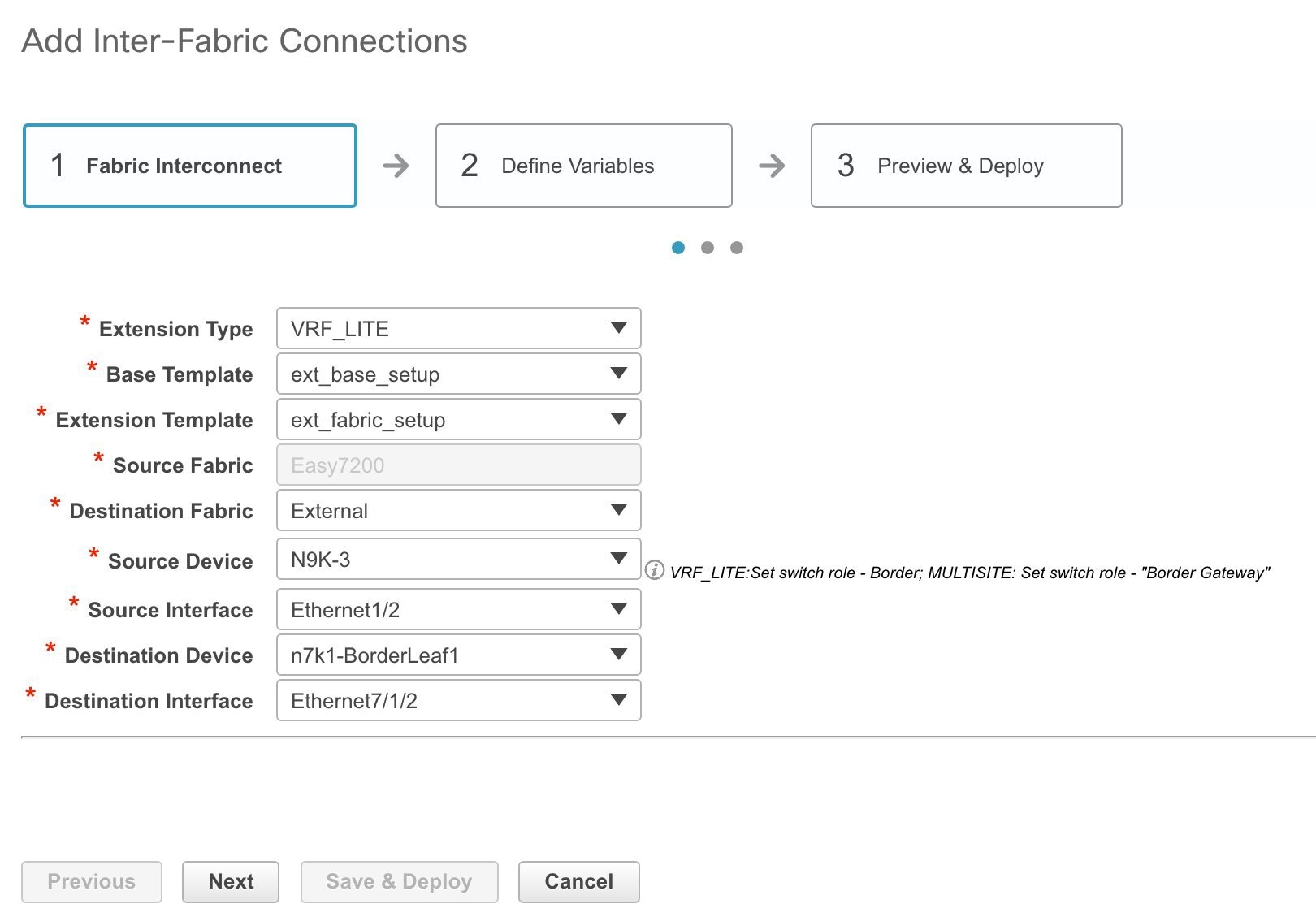
Click on the Add icon to add a new external connection. The Add Inter-Fabric Connections screen appears.
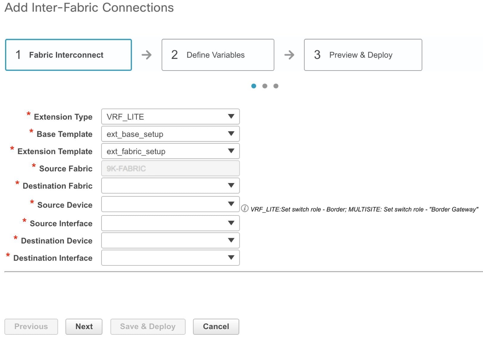
Fill up the fields on this page. The Source Fabric field is pre-populated in the Fabric Interconnect section. By default, the Extension Type is set to VRF_LITE. The Base template references the template that contains a one-time configuration pushed to border devices. The Extension Template references the setup template that contains the configuration that is generated and pushed to the border device to set up the corresponding inter-fabric connection. These templates are auto-populated with corresponding pre-packaged default templates based on user selections. The destination fabric that contains the external device peer must be selected. Note that based on the selection of the source device and source interface, the destination information is autopopulated based on CDP information if available. There is extra validation performed to ensure that the destination external device is indeed part of the destination fabric.
-
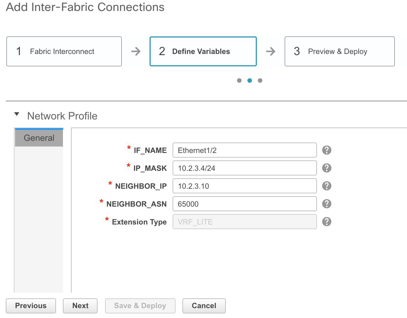
Click Next to go to the Define Variables section.
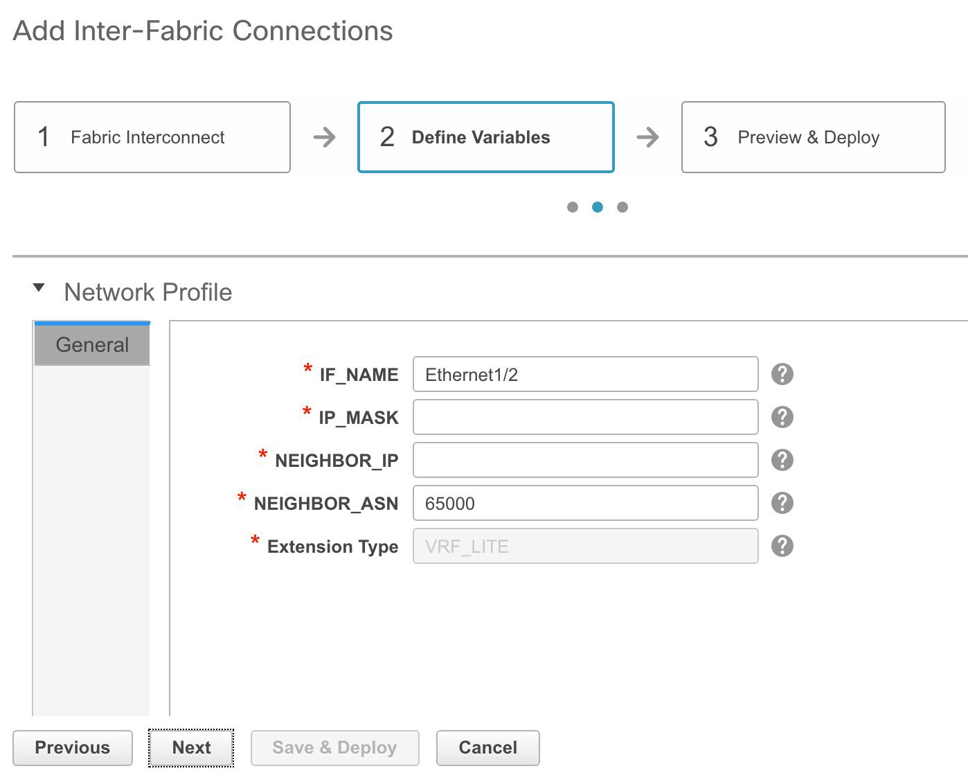
Here, the source interface name, destination fabric ASN, and the extension type are autopopulated. The template variables are parsed from the templates that are selected in the previous step and displayed for user input. All mandatory parameters must be entered.
-
Click Next to go to the Preview and Deploy section.
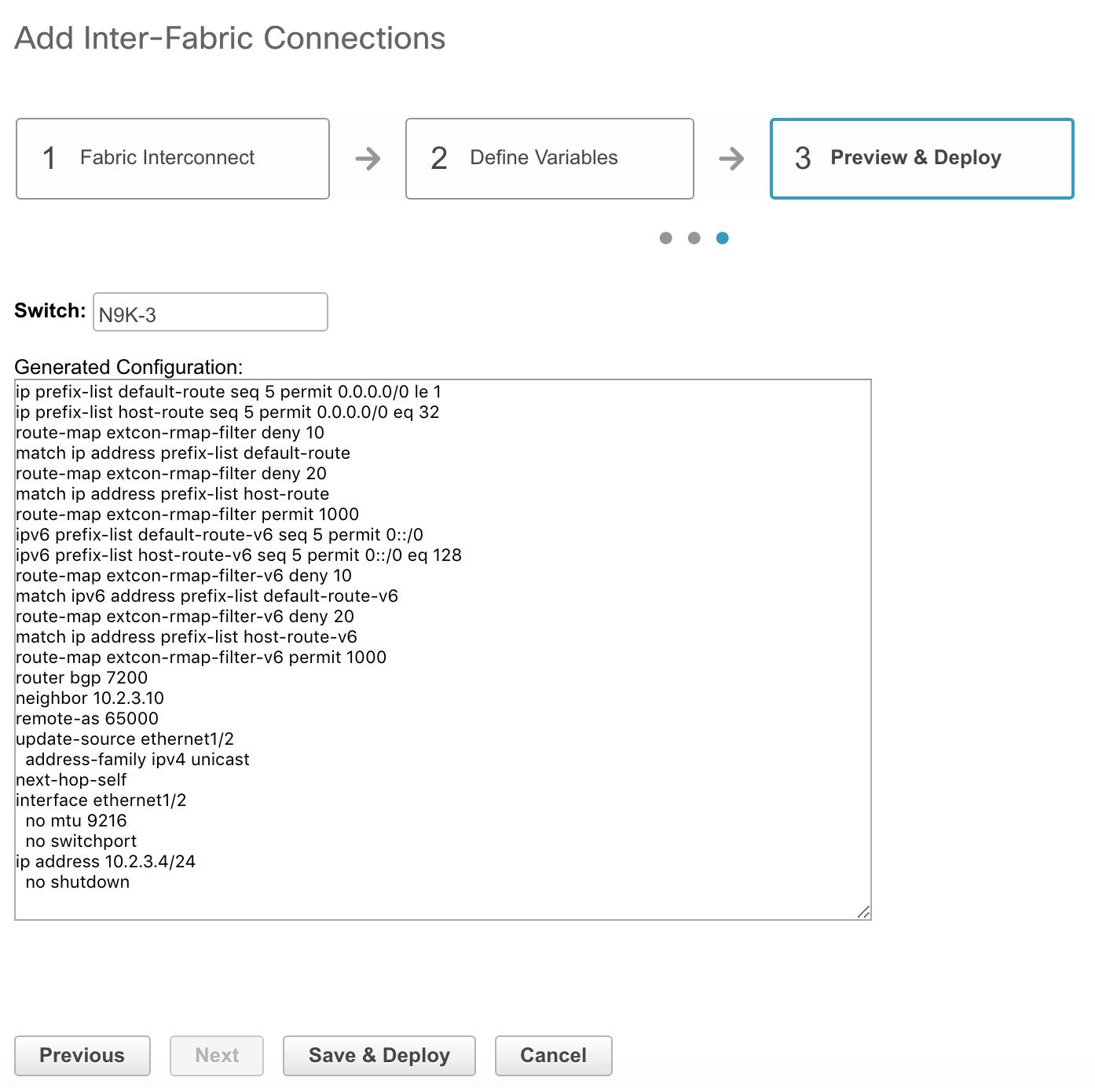
Here, you can preview the configuration that is deployed to the selected border device. Note that no configuration is pushed to the external device itself.
-
Click Save and Deploy to complete the task.
This results in the configuration getting pushed to the appropriate border node. The external connection appears in the Fabric Extension screen.
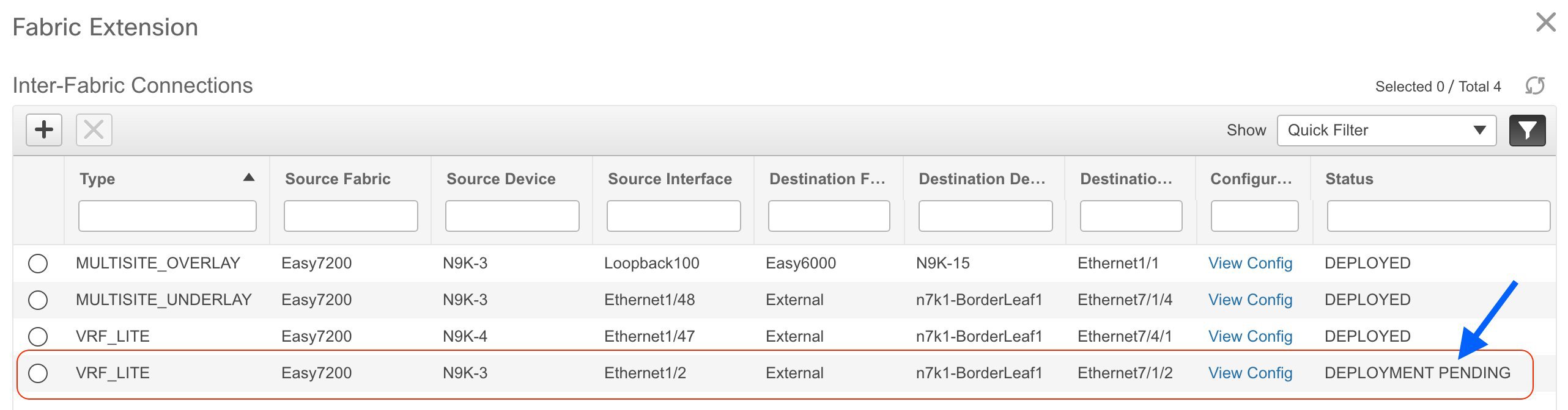
You can check the status of the deployment (Pending, Deployed, Failed so on) in the Status column. In case of FAILED or UNDEPLOYMENT FAILED status, use the hyperlink in the Status column to check the error messages for failure.
In this case, the status will change to DEPLOYED after the screen refresh. The sample topology displays the external connection, including the border device being connected to the external fabric.
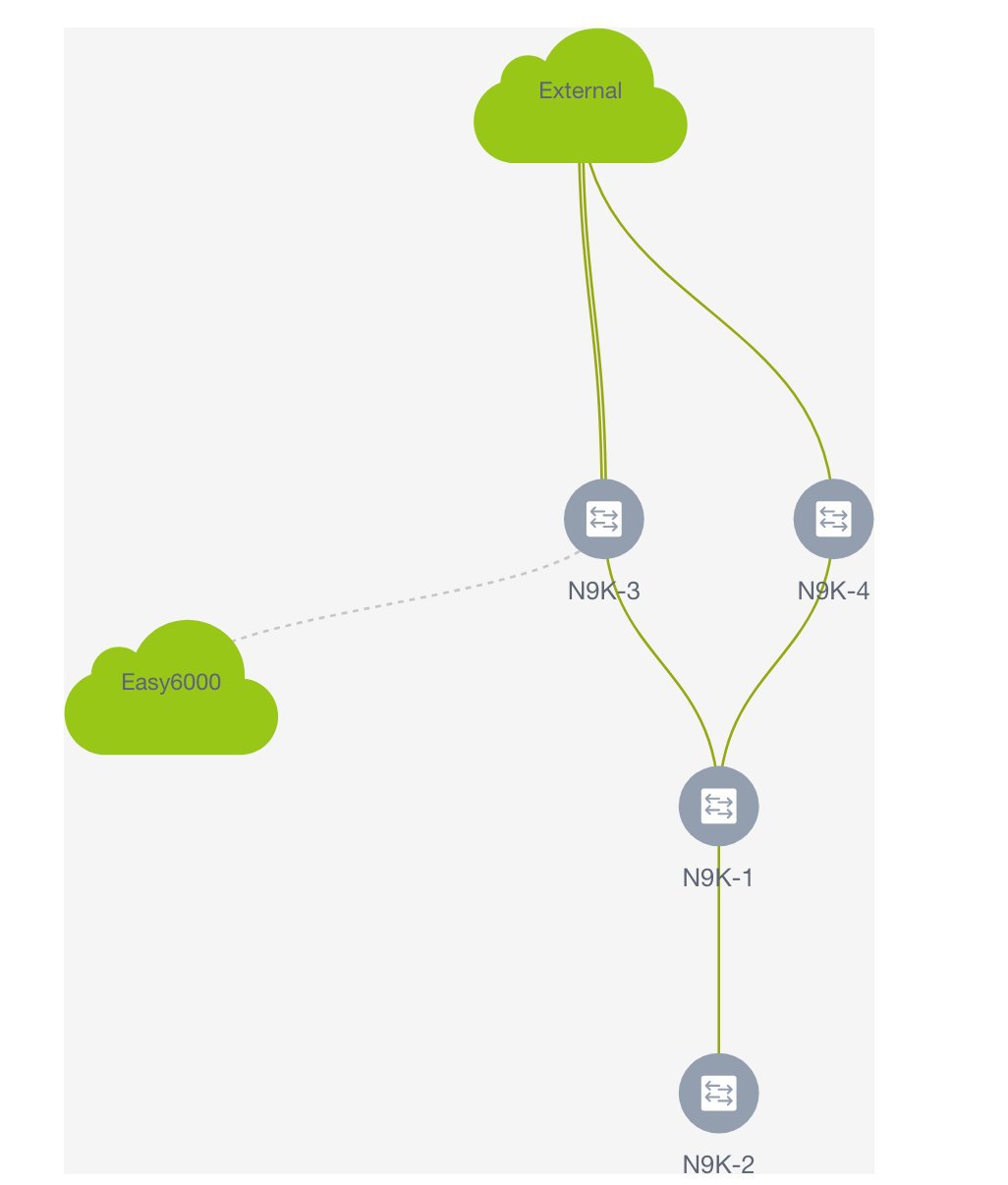
For additional inter-fabric connections, a similar set of steps is repeated. Note however, the base configuration to the border node is only pushed once, when the first inter-fabric connection is deployed for a given type. The connections can either be added or deleted, they cannot be updated or edited. On successful deployment of the inter-fabric connections, in the LAN Fabric provisioning topology view, each inter-fabric connection is displayed as an edge (solid for physical or dotted for logical) between the appropriate border node and the external fabric. Note that individual devices in the external fabric are not shown and only a cloud icon with the fabric name is displayed.
Note
You can delete an IFC connection only if it is not attached to any network or VRF.
Post DCNM 10.4(2) to DCNM 11.0(1) Upgrade Procedure for VXLAN BGP EVPN Fabrics
This topic provides details on the procedure to gracefully on board a DCNM 10.4(2) managed VXLAN BGP EVPN fabric comprising Cisco Nexus 9000 switches, post upgrade to DCNM 11.0(1). The assumption is that the fabric was deployed with DCNM 10.4(2), including the underlay (via the DCNM published POAP templates) and the overlays including configuration on the border devices (optional). The DCNM provided POAP templates and the overlay profile templates themselves may have been customized for the desired deployment.
Before you begin - It is assumed that you have installed the Cisco DCNM 11.0(1) software. If not, follow the Upgrade process to upgrade from DCNM 10.4(2) to DCNM 11.0(1). After installation, follow the guidelines and start migrating devices to DCNM 11.0(1).
Note |
The term upgrade in this section refers to the actions of migrating the switches to the DCNM 11.0(1) release in the DCNM GUI and deployment of new configuration policies on the switches. |
Guidelines and Limitations
-
The assumption is that the fabric was operational and functional when it is being managed with DCNM 10.4(2). In other words, the underlay and overlays have been deployed to the switches in a consistent manner and the BGP sessions, VNIs, and so on, that are configured are part of a functional fabric.
-
The switch roles (leaf, border, and so on) are retained from what they were set in DCNM 10.4.2 (prior DCNM). The assumption is that the roles were correctly set and hence the roles must not be changed during the migration process.
-
As part of the migration process, DCNM reads the running configuration from every switch within the migrating fabric, and specifically for the VXLAN BGP EVPN underlay configuration, it does a match to reverse population of that state into the DCNM against the packaged best-practice policy templates. In other words, it infers the underlay intended state from the existing running configuration on the switches. The state of the overlay configuration from DCNM 10.4(2) is retained during the upgrade to DCNM 11.0(1).
-
Configurations that are not supported in the upgrade or migration process are:
-
Manual VLAN and SVI (barring vPC peer link VLAN) configurations (that are not overlay related) - These are configurations that were not enabled as part of the DCNM 10.4(2) top down tenant configurations.
-
Loopback interface configurations other than loopback0, loopback1, and loopback254 interfaces. The assumption is that loopback0 is employed for BGP/IGP peering, loopback1 is employed for VTEPs, and loopback 254 is employed for the RP configuration on the spines (if applicable).
-
Subinterfaces (not provisioned via VRF-Lite extensions on the Borders via DCNM).
After the upgrade is complete, you can add these configurations to the appropriate switches as needed using the switch_freeform_config policy (Refer Freeform Configurations on Fabric Switches for details). This ensures that the configuration is captured in DCNM as part of the intended configuration, hence, the configuration compliance module ensures that the intent is synchronized against the current running configuration with appropriate OUT-OF-SYNC/IN-SYNC status notification.
-
-
vPC switches – Ensure that the following configurations are present on vPC switches as is expected for a typical functioning vPC pair in a VXLAN BGP EVPN fabric.
-
Secondary IP address on loopback1 (the loopback that is mapped to the NVE or VTEP interface).
-
vPC peer link port channel and member interfaces.
-
vPC peer link backup SVI and VLAN.
If the switch is not a Cisco Nexus 9000 series switch with Cloud-scale ASICs, the peer link VLAN also needs to be specified in the system nve infra-vlans command.
If the above configurations are missing, the upgrade will fail and the system will display an error message. To resolve the issue, you should enable correct vPC configurations and use the Save and Deploy option (explained during the upgrade process) to proceed with the upgrade.
-
-
You can add more switch instances to the fabric after the upgrade process in the DCNM GUI. Refer the Add Switch Instances in the Fabric section for additional details.
-
Policies created for the fabric underlay (for example, for fabric interfaces and routing) are created with the source set as UNDERLAY. These policies cannot be modified.
Upgrade Procedure in the DCNM GUI
-
Open a web browser and log on to the DCNM 11.0(1) Web UI https://<DCNM-IP> with the appropriate credentials.
-
Choose Control > Fabric Builder. The fabrics that were managed by DCNM 10.4(2) will be displayed in blue color. The blue color indicates that the fabric has been recognized as something that has been successfully imported from DCNM 10.4(2), but this fabric needs to be associated with an appropriate fabric template. In this screenshot, a single fabric is displayed.
-
Click the wheel icon of the fabric to associate it with an appropriate fabric template. The Edit Fabric screen comes up.
-
From the Fabric Template drop-down box, select Easy_Fabric.
-
Update fabric parameters in accordance with the currently selected fabric. Recall that this is a functional fabric. The current support is present only for fabrics setup with underlay using IGP as IS-IS or OSPF. The BUM handling mechanism may be multicast or ingress-replication. The values entered should match the DCNM 10.4(2) fabric’s parameters.
Specifically, ensure that the following values are the same as the switch configurations:
-
BGP AS Number.
-
Fabric underlay routing protocol (IS-IS or OSPF).
-
Replication mode (Multicast or Ingress Replication).
-
Fabric interface numbering (p2p or IP unnumbered).
-
vPC peer link VLAN, if vPC is present.
-
vPC delay restore time and other related parameters in the Advanced tab
Manageability tab – To retain existing DNS, NTP and AAA configurations, clear the corresponding fields in this tab. Policies will be created using the source "". If you update any of the settings here, the settings will override corresponding switch configurations.
You can also update the DNS, NTP and AAA parameters after the migration.
-
-
Click Save to save the updated settings.
The topology screen comes up. This screen displays the existing devices and their connections. Since the devices are yet to be migrated to DCNM 11.0(1), the Migration-mode icon will be displayed on each switch. Validate that the roles have been appropriately retained from the DCNM 10.4(2) upgrade.
-
Click Save & Deploy at the top right part of the screen to start the migration process.
Policy creation is initiated based on existing device configuration and how the devices are connected with each other. At this point, the policy creation in terms of the underlay intent is inferred from the running configuration of every device. In case there is a mismatch found between the switch configuration and the inputs provided in the Fabric Settings, an appropriate error will be reported. You must make appropriate changes to address the reported error before proceeding to execute “Save & Deploy” again. Addressing the error may involve making changes to the switch configuration on which the error was reported or making edits to the Fabric Settings or potentially customize policies to match the running configuration. You can see a message at the center of the screen indicating that the intended configuration for every switch in the fabric is being generated in the DCNM.
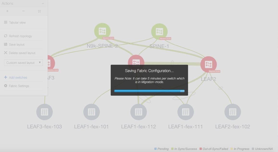
Note that this process may take a while depending on the number of switches that are part of the fabric and the size of the running configuration, which is a function of the number of networks and VRFs deployed on the switches. Once this process has been successfully completed, next, the Config Deployment screen comes up as shown below.
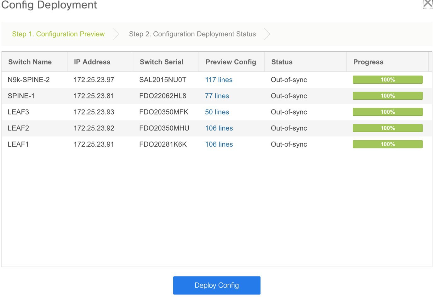
This screen displays all the switches within the fabric with the Status column indicating whether the switches are IN-SYNC or OUT-OF-SYNC as per calculations from the Config Compliance module. You can click within the Preview Config column for a row that represents a specific switch, for more information. When you do so, the Config Preview screen comes up.
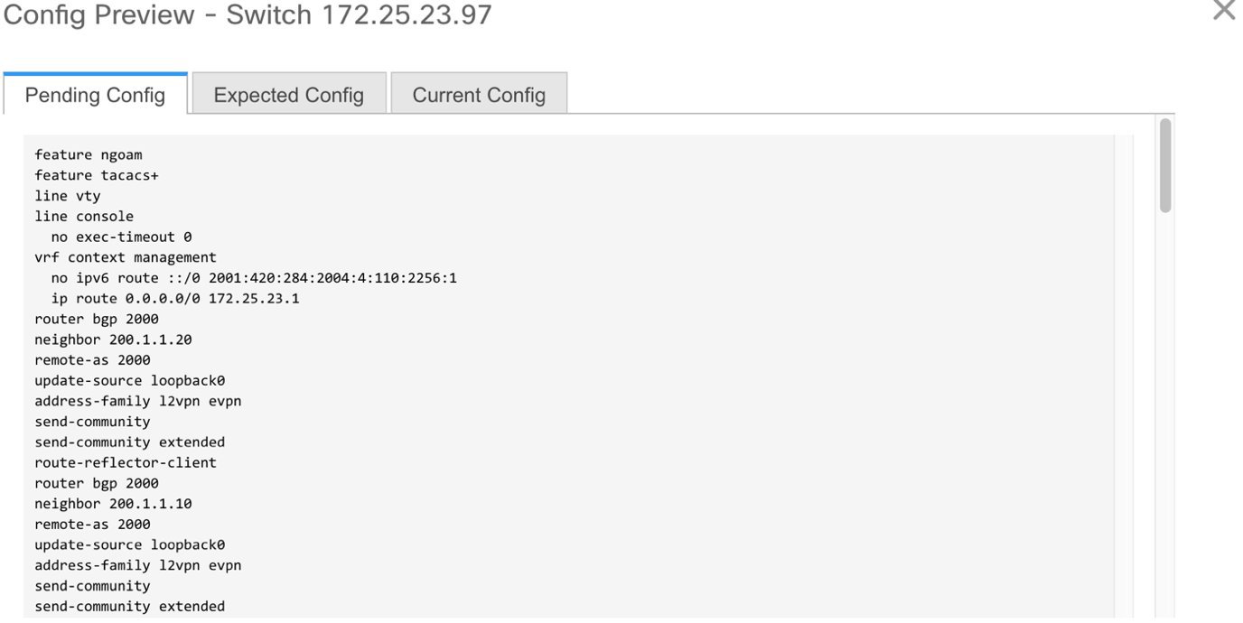
The Pending Config tab displays the set of configuration that needs to be deployed on the switch, to go from the current running configuration to the current expected/intended configuration. Note that the amount of configuration that shows up in the pending config tab needs to be carefully reviewed before deployment. Typically, if there is even a single line of difference in the configuration associated with a given policy associated with an ENTITY, be it a given interface or a given feature, the pending config will show the entire configuration associated with that policy.
The Expected Config and Current Config tabs display the expected and current configurations on the switch, respectively. After expected configurations are generated, the switches will be out of Migration-mode.
Close the screen after previewing it. The Config Deployment screen comes up again. Preview other switch configurations as needed.
-
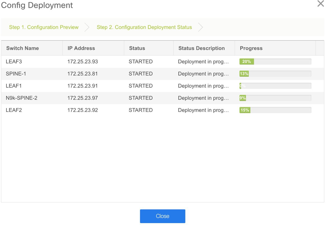
Click Deploy Config at the bottom part of the Config Deployment screen to deploy pending configurations to the switches. This shows up Step 2 of the deployment process, where a per switch deployment status is depicted with an appropriate progress bar. In case there are any errors encountered during the deployment process, the deployment process for that particular switch, will be aborted with a “FAILED” status. The deployment on all the other switches continues to be executed in parallel. For the failure case, by clicking on the “FAILED” status, a pop-up will open up where the details of the configuration deployment history for the switch will be depicted. This in turn can be used to drill down into the exact error that was encountered during the deployment. After addressing the error, the deployment can be re-attempted.
The Progress column displays the deployment progress on each switch.
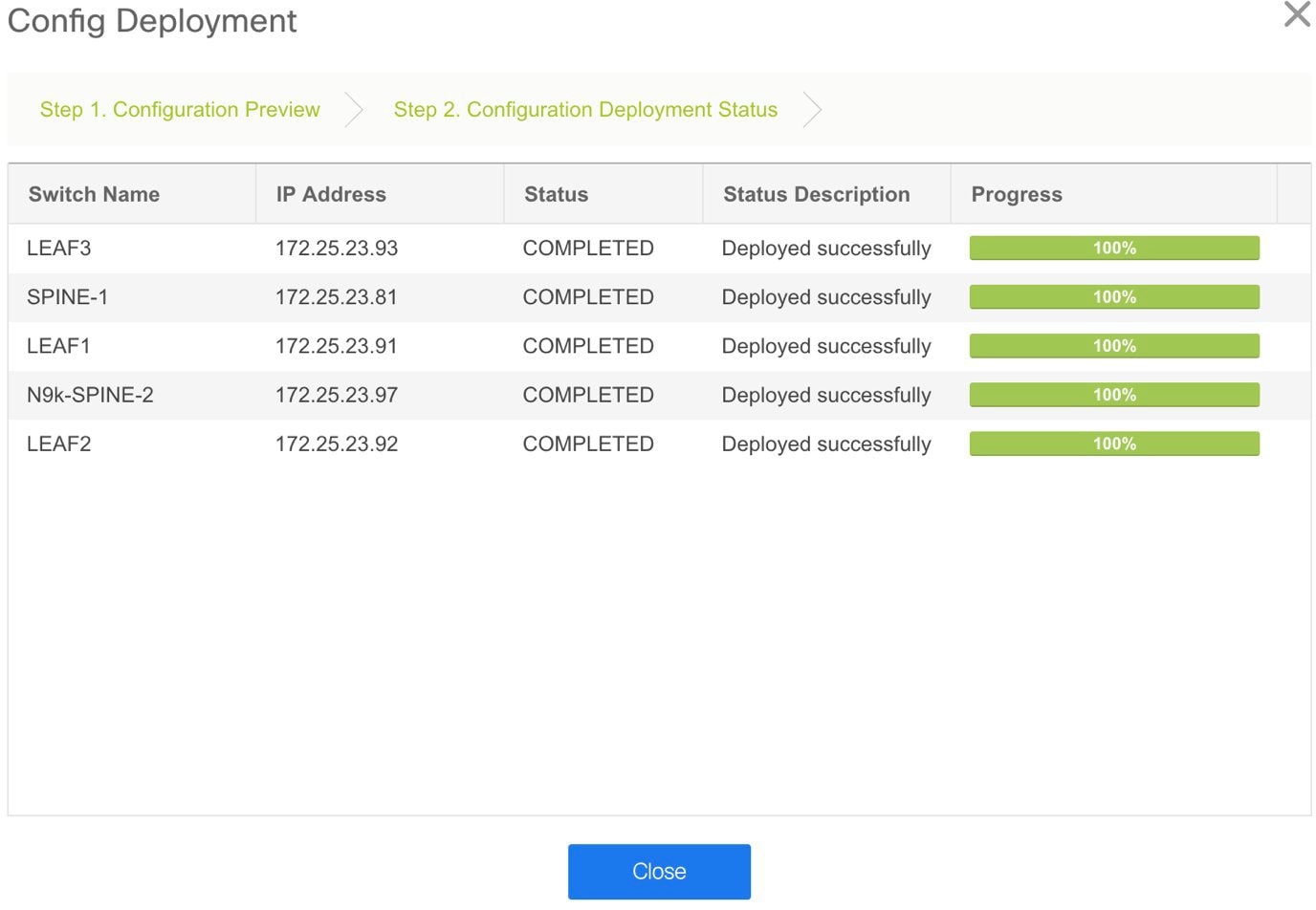
For a successful deployment and an IN-SYNC status for the entire fabric, ensure that the progress column shows 100% for all switches.
-
Click Close.
The fabric topology will be displayed. You can see that the Migration-mode icon is no longer visible on the switches and the switch icons are in green color indicating an IN-SYNC status as regards to Configuration Compliance. In this way, the migration/onboarding of the fabric has been achieved.
Multi-Site Domain for VXLAN BGP EVPN Fabrics
A Multi-Site Domain (MSD) is a multifabric container that is created to manage multiple member fabrics. An MSD is a single point of control for definition of overlay networks and VRFs that are shared across member fabrics. When you move fabrics (that are designated to be part of the multifabric overlay network domain) under the MSD as member fabrics, the member fabrics share the networks and VRFs created at the MSD-level. This way, you can consistently provision network and VRFs for different fabrics, at one go. It significantly reduces the time and complexity involving multiple fabric provisionings.
Since server networks and VRFs are shared across the member fabrics (as one stretched network), the new networks and VRFs provisioning function is provided at the MSD fabric level. Any new network and VRF creation is only allowed for the MSD. All member fabrics inherit any new network and VRF created for the MSD.
Note |
|
A few fabric-specific terms:
-
Standalone fabric: A fabric that is not part of an MSD is referred as a standalone fabric from the MSD perspective. Before the MSD concept, all fabrics were considered standalone, though two or more such fabrics can be connected with each other.
-
Member fabrics: Fabrics that are part of an MSD are called member fabrics or members. Create a standalone fabric (of the type Easy_Fabric) first and then move it within an MSD as a member fabric.
When a standalone fabric is added to the MSD, the following actions take place:
-
The standalone fabric's relevant attributes and the network and VRF definitions are checked against that of the MSD. If there is a conflict, then the standalone fabric addition to the MSD fails. If there are no conflicts, then the standalone fabric becomes a member fabric for the MSD. If there is a conflict, the exact conflicts are logged in the pending errors log for the MSD fabric. You can remedy the conflicts and then attempt to add the standalone fabric to the MSD again.
-
All the VRFs and networks definitions from the standalone fabric that do not have presence in the MSD are copied over to the MSD and in turn inherited to each of its other existing member fabrics.
-
The VRFs (and their definitions) from the MSD (such as the MSD's VRF, and L2 and L3 VNI parameters that do not have presence in the standalone fabric) are inherited into the standalone fabric that just became a member.
Fabric and Switch Instance Variables
While the MSD provisions a global range of network and VRF values, some parameters are fabric-specific and some parameters are switch-specific. The parameters are called fabric instance and switch instance variables.
Fabric instance values can be edited in the fabric context. Specify fabric instance values for each fabric. For example, multicast group subnet address.
Switch instance values can be edited on deployment of the network on the switch. For example, VLAN ID.
MSD and Member Fabric Process Flow
An MSD has multiple sites (and hence, multiple member fabrics under an MSD). VRFs and networks are created for the MSD and get inherited by the member fabrics. For example, VRF-50000 (and L3 network with ID 50000), and L2 networks with IDs 30000 and 30001 are created for the MSD, in one go.
A high-level flow chart of the MSD and member fabric creation and MSD-to-member fabric inheritance process:
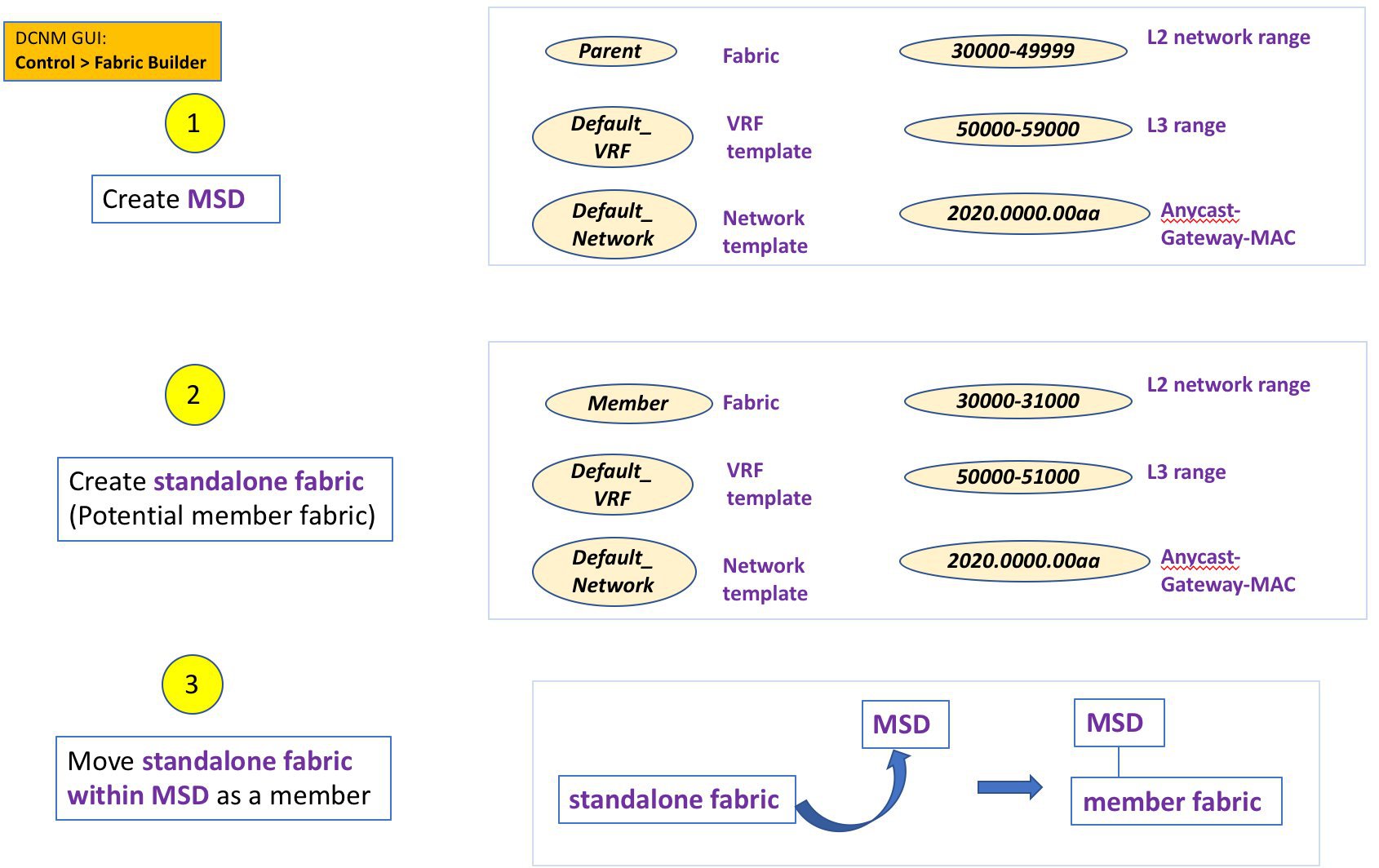
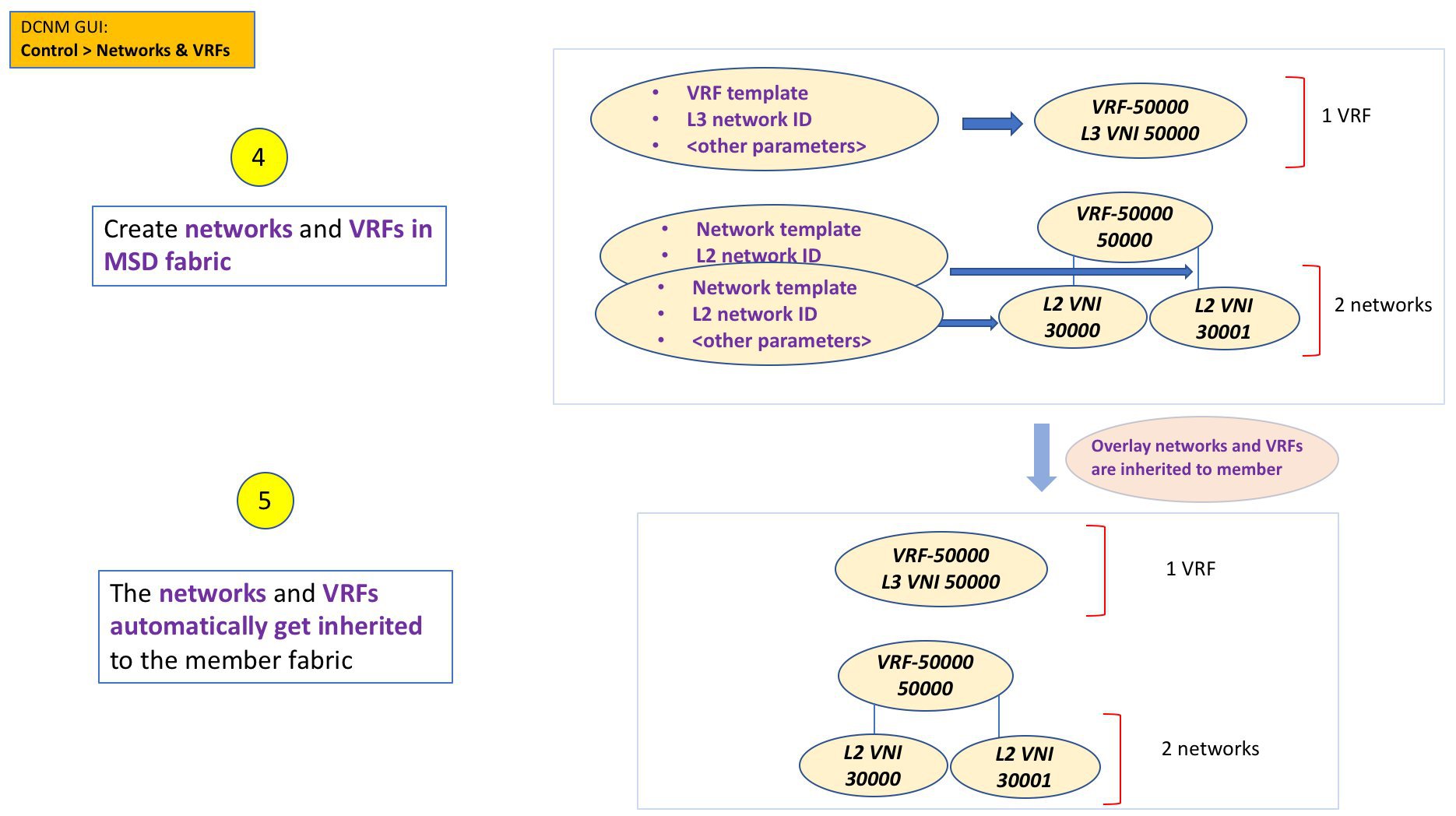
The sample flow explained the inheritance from the MSD to one member. An MSD has multiple sites (and hence, multiple member fabrics under an MSD). A sample flow from an MSD to multiple members:
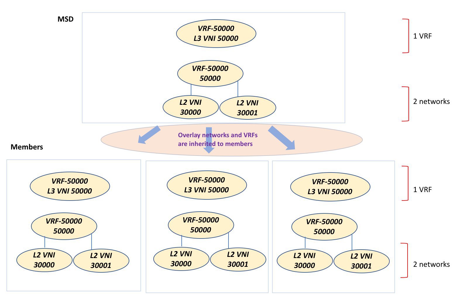
In this example, VRF-50000 (and L3 network with ID 50000), and L2 networks with IDs 30000 and 30001 are created in one go. Networks and VRFs are deployed on the member fabric switches, one after another, as depicted in the image.
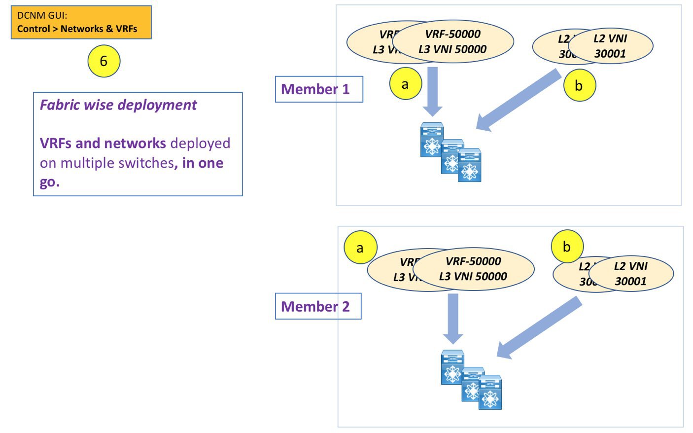
Note |
If you move a standalone fabric with existing networks and VRFs to an MSD, DCNM does appropriate validation. This is explained in detail in an upcoming section. |
Upcoming sections in the document explain the following:
-
Creation of an MSD fabric.
-
Creation of a standalone fabric (as a potential member) and its movement under the MSD as a member.
-
Creation of networks and VRFs in the MSD and their inheritance to the member fabrics.
-
Deployment of networks and VRFs in a member fabric's switches.
-
Other scenarios for fabric movement:
-
Standalone fabric with existing networks and VRFs to an MSD fabric.
-
Member fabric from one MSD to another.
-
Create an MSD Fabric and Associate Member Fabrics to It
The process is explained in two steps:
-
Create an MSD fabric.
-
Create a new standalone fabric and move it under the MSD fabric as a member fabric.
Create an MSD Fabric
-
Click Control > Fabric Builder.
The Fabric Builder page comes up. When you enter for the first time, the Fabrics section has no entries. After you create a fabric, it is displayed on the Fabric Builder page, wherein a rectangular box represents each fabric.
A standalone or member fabric contains Switch_Fabric in the Type field, its AS number in the ASN field and mode of replication, Multicast or Ingress Replication, in the Replication Mode field. Since no device or network traffic is associated with an MSD fabric as it is a container, it does not have these fields.
-
Click the Create Fabric button. The Add Fabric screen comes up. The fields are:
Fabric Name - Enter the name of the fabric.
Fabric Template - This field has template options for creating specific types of fabric. Choose MSD_Fabric. The MSD screen comes up.
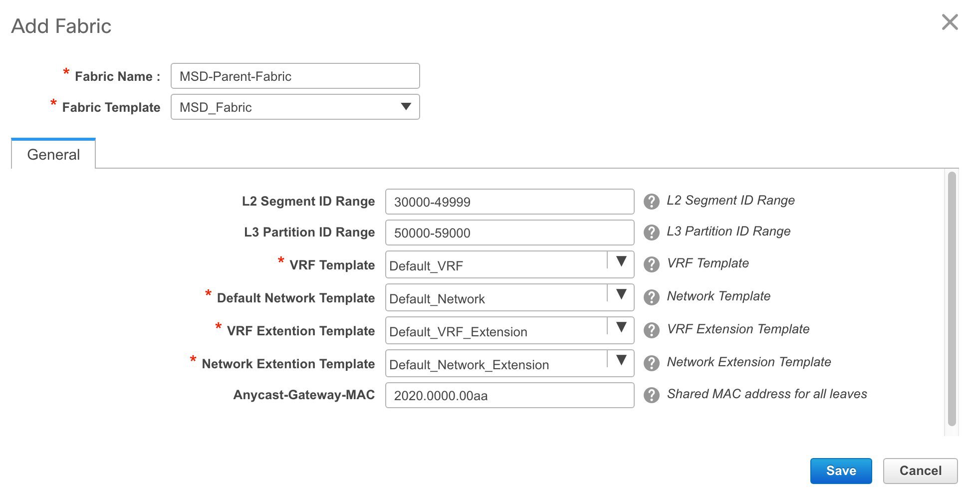
The fields in the screen are explained:
In the General tab, all fields are autopopulated with data. The fields consist of the Layer 2 and Layer 3 VXLAN segment identifier range, the default network and VRF templates, and the anycast gateway MAC address. Update the relevant fields as needed.
L2 Segment ID Range - Layer 2 VXLAN segment identifier range.
L3 Partition ID Range - Layer 3 VXLAN segment identifier range.
VRF Template - Default VRF template.
Default Network Template - Default network template.
VRF Extension Template - Default VRF extension template.
Network Extension Template - Default network extension template.
Anycast-Gateway-MAC - Anycast gateway MAC address.
-
Click Save.
A message appears briefly at the bottom right part of the screen, indicating that you have created a new MSD fabric. After fabric creation, the fabric page comes up. The fabric name MSD-Parent-Fabric appears at the top left part of the screen.
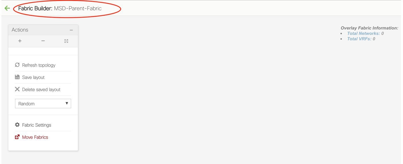
Since the MSD fabric is a container, you cannot add a switch to it. The Add Switches button that is available in the Actions panel for member and standalone fabrics is not available for the MSD fabric.
When a new MSD is created, the newly created MSD fabric instance appears (as a rectangular box) on the Fabric Builder page. To go to the Fabric Builder page, click the ← button at the top left part of the MSD-Parent-Fabric page.
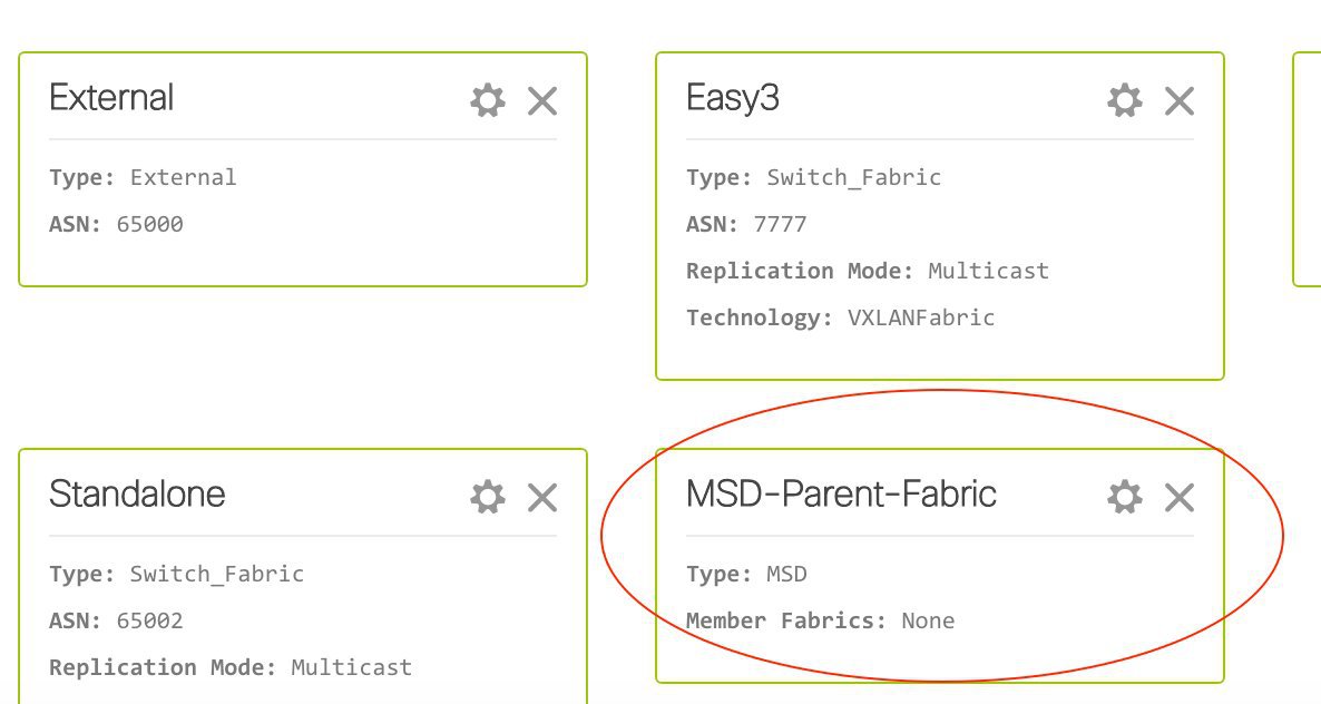
An MSD fabric is displayed as MSD in the Type field, and it contains the member fabric names in the Member Fabrics field. When no member fabric is created, None is displayed.
The steps for creation of an MSD fabric and moving member fabrics under it are:
-
Create an MSD fabric.
-
Create a new standalone fabric and move it under the MSD fabric as a member fabric.
Step 1 is completed. Step 2 is explained in the next section.
Create and Move a New Fabric Under the MSD Fabric as a Member
A new fabric is created as a standalone fabric. After you create a new fabric, you can move it under an MSD as a member. As a best practice, when you create a new fabric that is a potential member fabric (of an MSD), do not add networks and VRFs to the fabric. Move the fabric under the MSD and then add networks and VRFs for the MSD. That way, there will not be any need for validation (or conflict resolution) between the member and MSD fabric network and VRF parameters.
New fabric creation is explained in the Easy Fabric creation process. In the MSD document, fabric movement is covered. The values that are displayed in the screen are automatically generated. The VXLAN VNI ID ranges (in the L2 Segment ID Range and L3 Partition ID Range fields) allocated for new network and VRF creation are values from the MSD fabric segment ID range. If you want to update the VXLAN VNI ranges or the VRF and Network VLAN ranges, ensure the following:
-
If you update a range of values, ensure that it does not overlap with other ranges.
-
You must update one range of values at a time. If you want to update more than one range of values, do it in separate instances. For example, if you want to update L2 and L3 ranges, you should do the following:
-
Update the L2 range and click Save.
-
Click the Edit Fabric option again, update the L3 range and click Save.
-
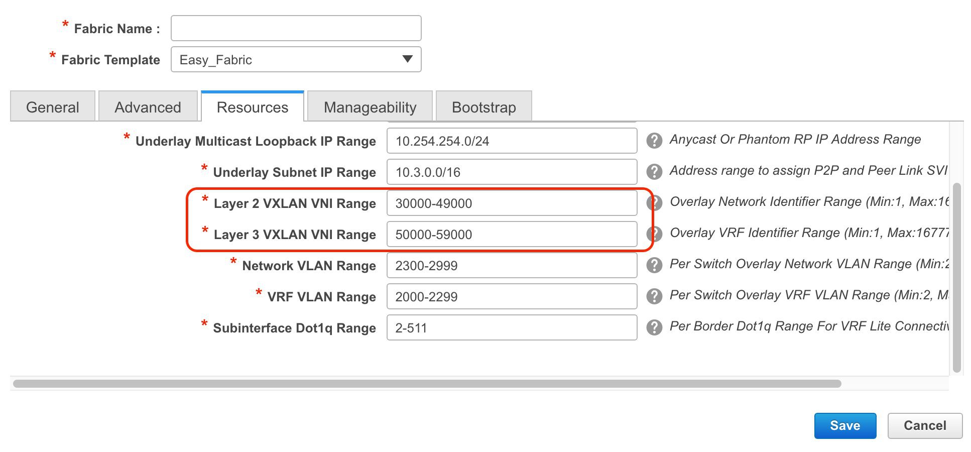
Ensure that the Anycast Gateway MAC, the Network Template and the VRF Template field values are the same as the MSD fabric. Else, member fabric movement to the MSD fail.
Other pointers:
-
The member fabric should have a Site ID configured and the Site ID must be unique among the members.
-
The BGP AS number should be unique for a member fabric.
-
The underlay subnet range for loopback0 should be unique.
-
The underlay subnet range for loopback1 should be unique.
After you click Save, a note appears at the bottom right part of the screen indicating that the fabric is created. When a fabric is created, the fabric page comes up. The fabric name appears at the top left part of the screen. Simultaneously, the Fabric Builder page also displays the newly created Member1 fabric.
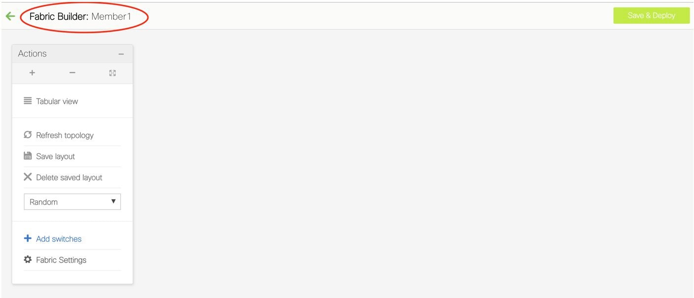
Simultaneously, the Fabric Builder page also displays the newly created fabric, Member1.
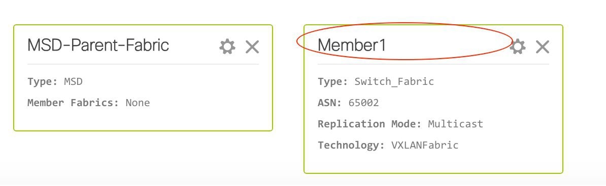
Move the Member1 Fabric Under MSD-Parent-Fabrics
You should go to the MSD fabric page to associate a member fabric under it.
If you are on the Fabric Builder page, click within the MSD-Parent-Fabric box to go to the MSD-Parent-Fabric page.
[If you are in the Member1 fabric page, you should go to the MSD-Parent-Fabrics-Docs fabric page. Click <- above the Actions panel. You will reach the Fabric Builder page. Click within the MSD-Parent-Fabric box].
-
In the MSD-Parent-Fabric page, go to the Actions panel and click Move Fabrics.
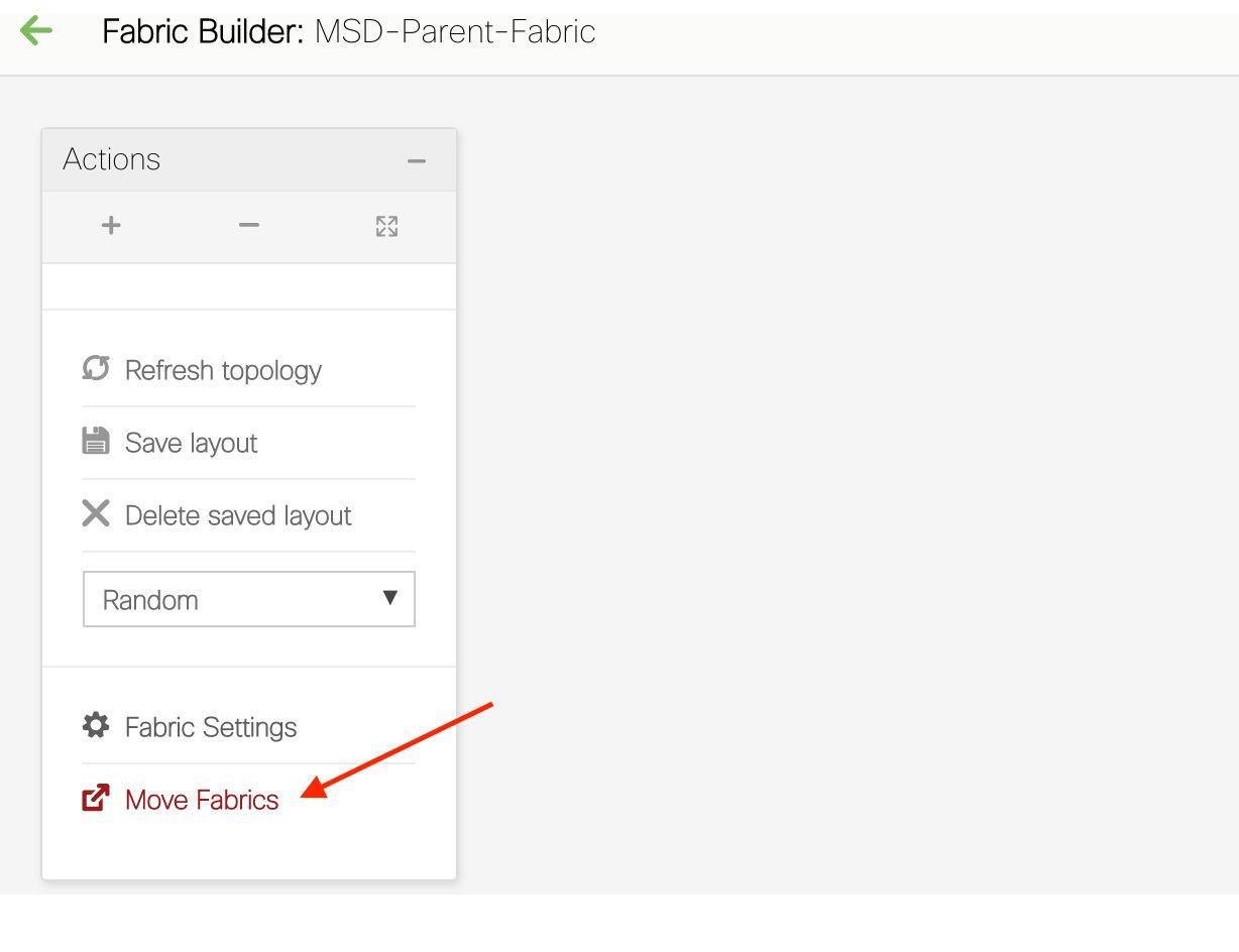
The Move Fabric screen comes up. It contains a list of fabrics.
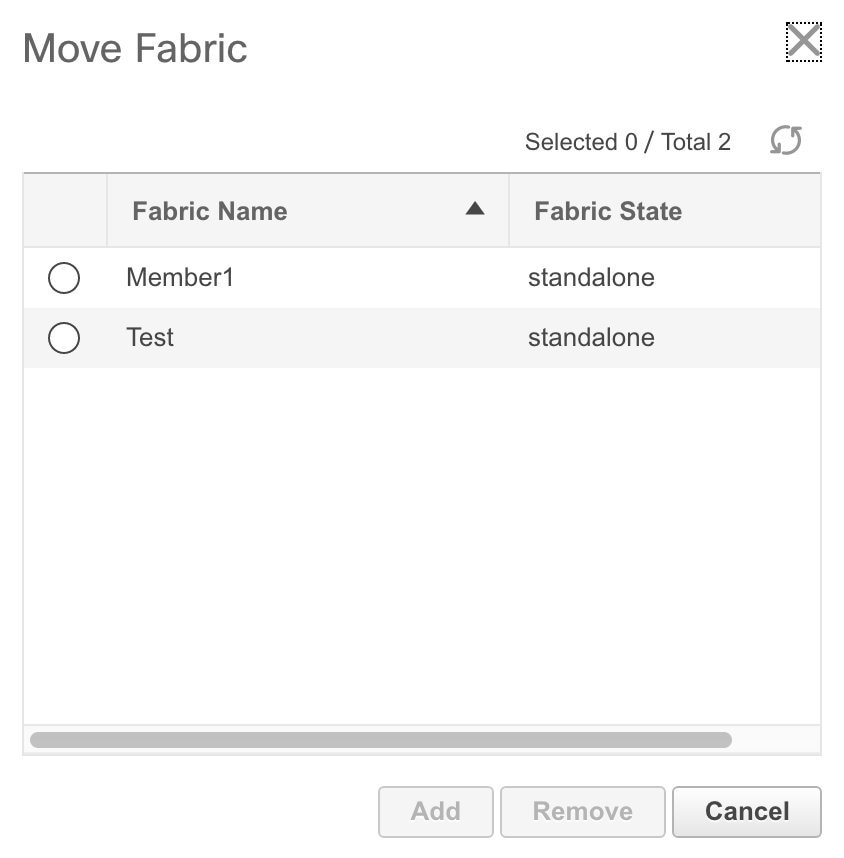
Member fabrics of other MSD container fabrics will not be displayed here.
The Member1 fabric is still a standalone fabric as seen in the image. A fabric is considered a member fabric of an MSD fabric only when you associate it with the MSD fabric. Also, each standalone fabric is a candidate for being an MSD fabric member, until you associate it to one of the MSD fabrics.
-
Since Member1 fabric is to be associated with the MSD fabric, select the Member1 radio button. The Add button is enabled.
-
Click Add.
Immediately, a message appears at the top of the screen indicating that the Member1 fabric is now associated with the MSD fabric MSD-Parent-Fabric. Now, the MSD-Parent-Fabric fabric page appears again.
-
Click the Move Fabrics option to check the fabric status. You can see that the fabric status has changed from standalone to member.
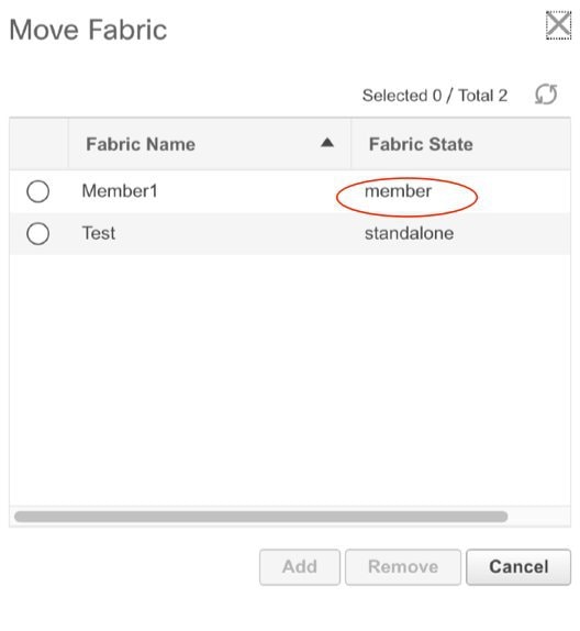
-
Close this screen. Now, in the MSD-Parent-Fabric screen the member fabric icon is displayed.
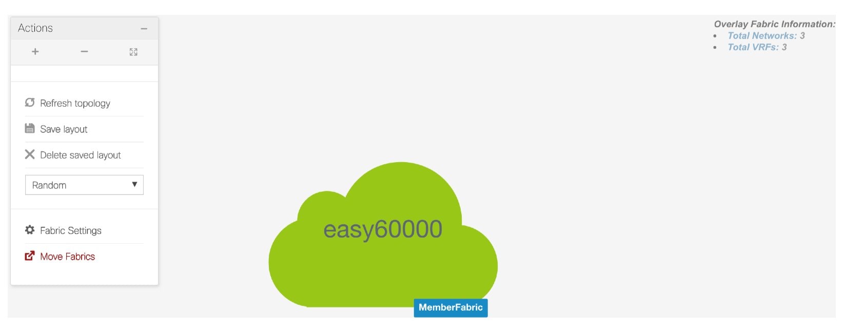
-
Click ← above the Actions panel to go to the Fabric Builder page.
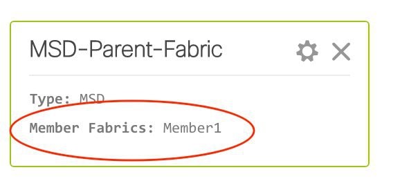
You can see that Member1 is now added to MSD fabric and is displayed in the Member Fabrics field.
Networks and VRFs Creation and Deployment in an MSD Fabric
In standalone fabrics, networks and VRFs are created for each fabric. In an MSD fabric, networks and VRFs should be created at the MSD fabric level. The networks and VRFs are inherited by all the member networks. You cannot create or delete networks and VRFs for member fabrics. However, you can edit them.
For example, consider an MSD fabric with two member fabrics. If you create three networks in the MSD fabric, then all three networks will automatically be available for deployment in both the member fabrics.
Though member fabrics inherit the MSD fabric's networks and VRFs, you have to deploy the networks and VRFs distinctly, for each fabric.
Note |
Networks and VRFs are the common identifiers (represented across member fabrics) that servers (or end hosts) are grouped under so that traffic can be sent between the end hosts based on the network and VRF IDs, whether they reside in the same or different fabrics. Since they have common representation across member fabrics, networks and VRFs can be provisioned at one go. As the switches in different fabrics are physically and logically distinct, you have to deploy the same networks and VRFs separately for each fabric. |
For example, if you create networks 30000 and 30001 for an MSD that contains two member fabrics, the networks are automatically created for the member fabrics and are available for deployment. But you have to deploy the networks 30000 and 30001 in one fabric, and then in the other.
Networks and VRFs are created in the MSD and deployed in the member fabrics. The steps are explained below:
-
Create networks and VRFs in the MSD fabric.
-
Deploy the networks and VRFs in the member fabric devices, one fabric at a time.
Create Networks in the MSD Fabric
-
Click Control > Networks & VRFs (under Fabrics submenu). The LAN Fabric Provisioning page comes up.
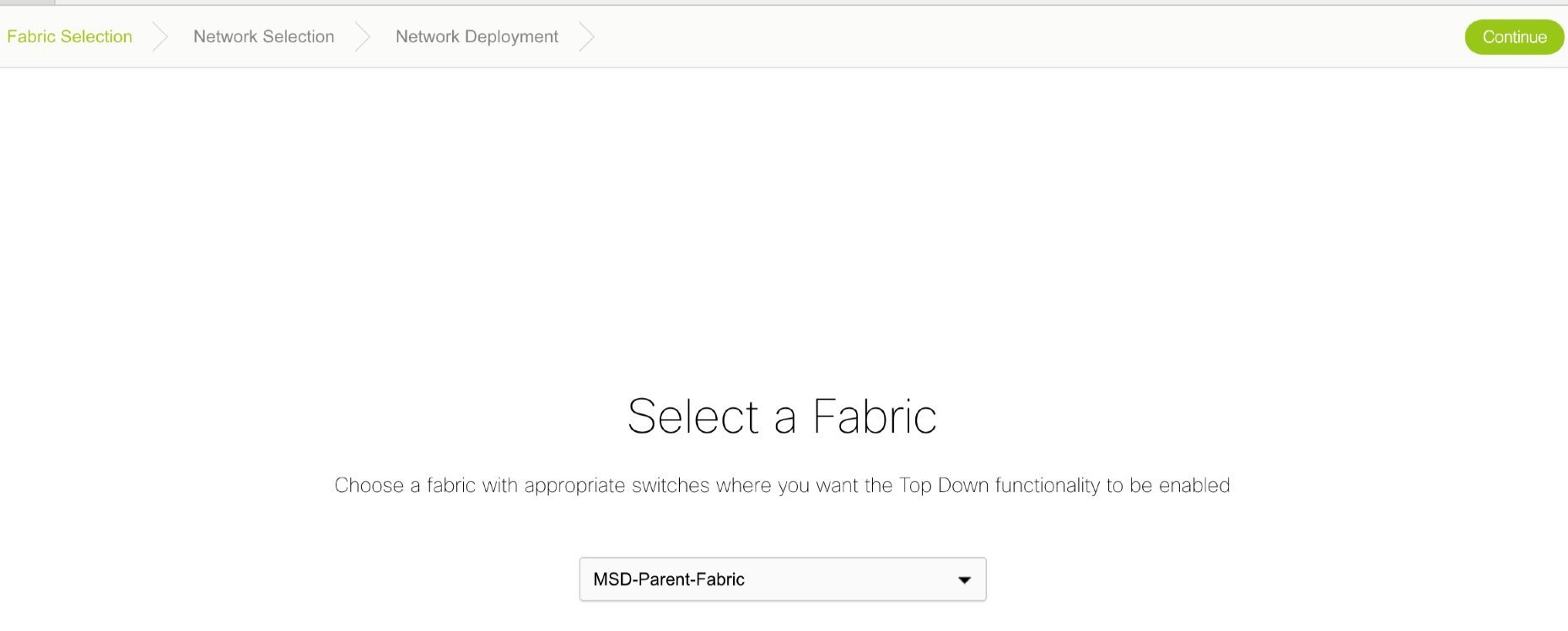
-
Click Continue. The Select a Fabric page comes up. Click the Select a Fabric drop-down box to see the list of fabrics.

The MSD fabric MSD-Parent-Fabric contains one member fabric, Member1. It is indented to the right, indicating that is a part of the MSD. All other standalone fabrics appear in the same indent level of the MSD.
Select MSD-Parent-Fabric from the list. The Select a Fabric screen for an MSD fabric comes up. Since this is a container of member fabrics and does not have any devices associated with it, associated device-relevant functions will not be seen in the GUI (for example, the Fabric Extension Setup option only appears for standalone and member fabrics).
-
Click Continue on the top right part of the screen. The Networks page comes up. This lists the list of networks created for the MSD fabric. Initially, this screen has no entries.
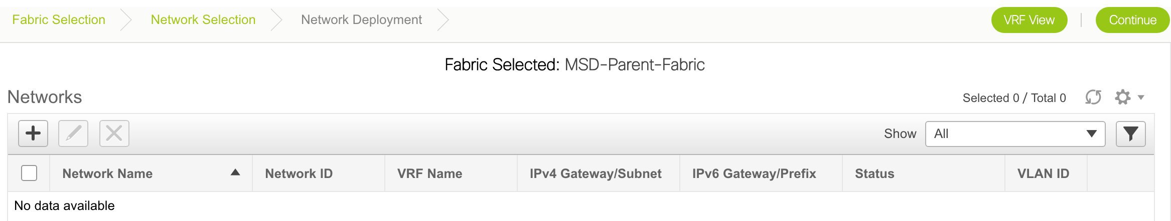
-
Click the + button at the top left part of the screen (under Networks) to add networks to the MSD fabric. The Create Network screen comes up. Most of the fields are autopopulated.
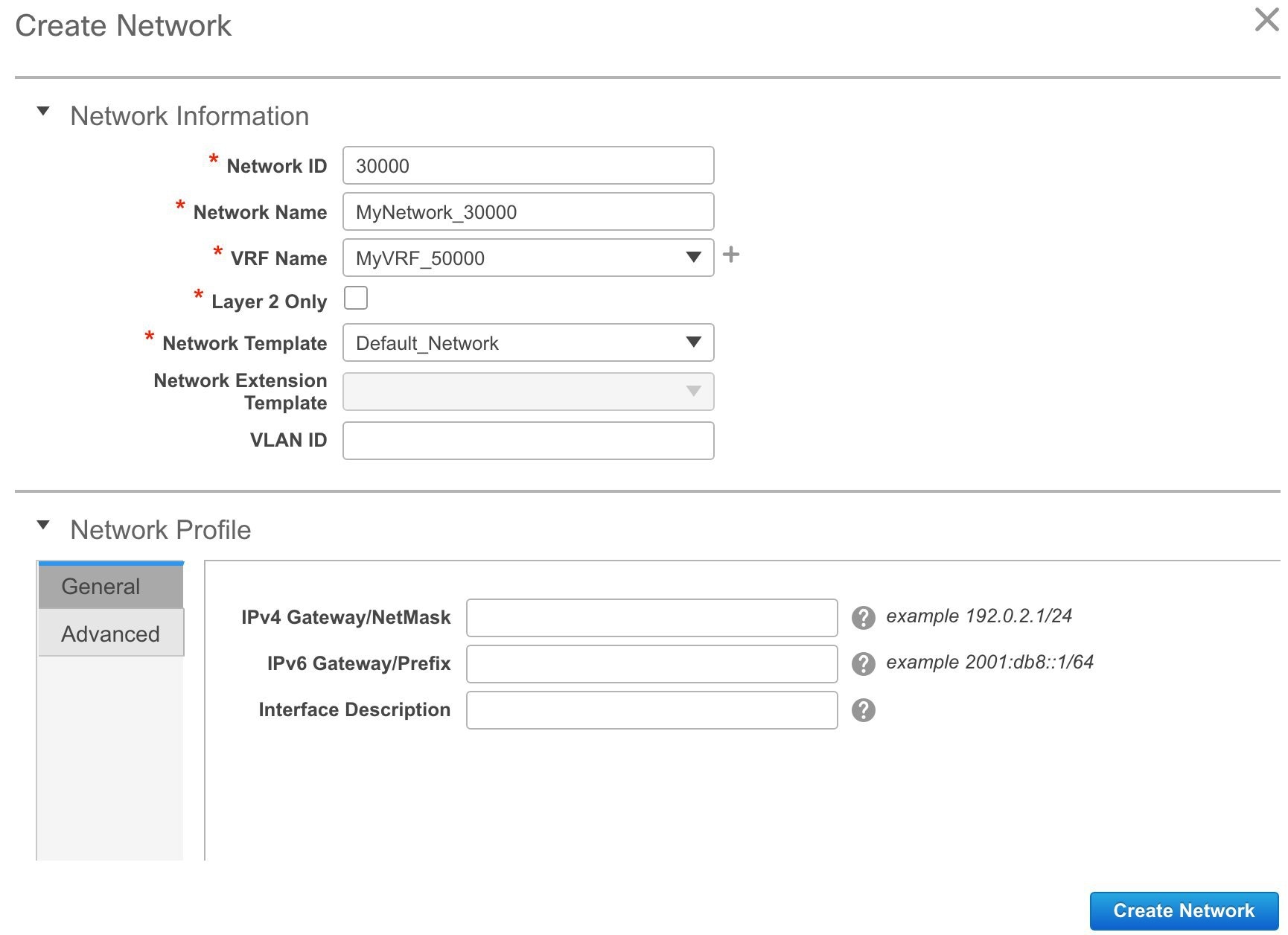
The fields in this screen are:
Network ID and Network Name - Specifies the Layer 2 VNI and name of the network. The network name should not contain any white spaces or special characters except underscore (_) and hyphen (-).
VRF Name - Allows you to select the Virtual Routing and Forwarding (VRF).
When no VRF is created, this field will be blank. If you want to create a new VRF, click the + button. The VRF name should not contain any white spaces or special characters except underscore (_), hyphen (-), and colon (:).
Note
You can also create a VRF by clicking the VRF View button on the Networks page.
Layer 2 Only - Specifies whether the network is Layer 2 only.
Network Template - Allows you to select a network template.
Network Extension Template - This template allows you to extend the network between member fabrics.
VLAN ID - Specifies the corresponding tenant VLAN ID for the network.
Network Profile section contains the General and Advanced tabs, explained below.
General tab
IPv4 Gateway/NetMask - Specifies the IPv4 address with subnet.
IPv6 Gateway/Prefix - Specifies the IPv6 address with subnet.
Interface Description - Specifies the description for the interface.
Advanced tab - Optionally, specify the advanced profile settings by clicking the Advanced tab. The options are:
-
ARP Suppression
-
DHCPv4 Server
-
DHCPv4 Server VRF
-
MTU for the L3 interface
A sample of the Create Network screen is given below.
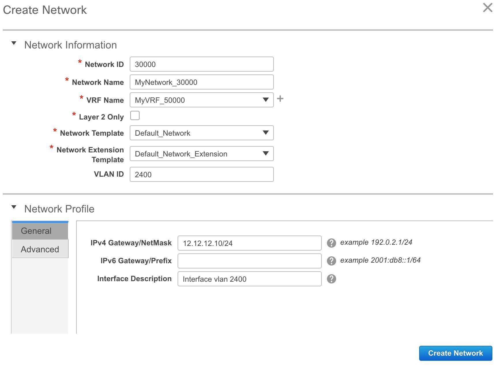
Advanced tab:
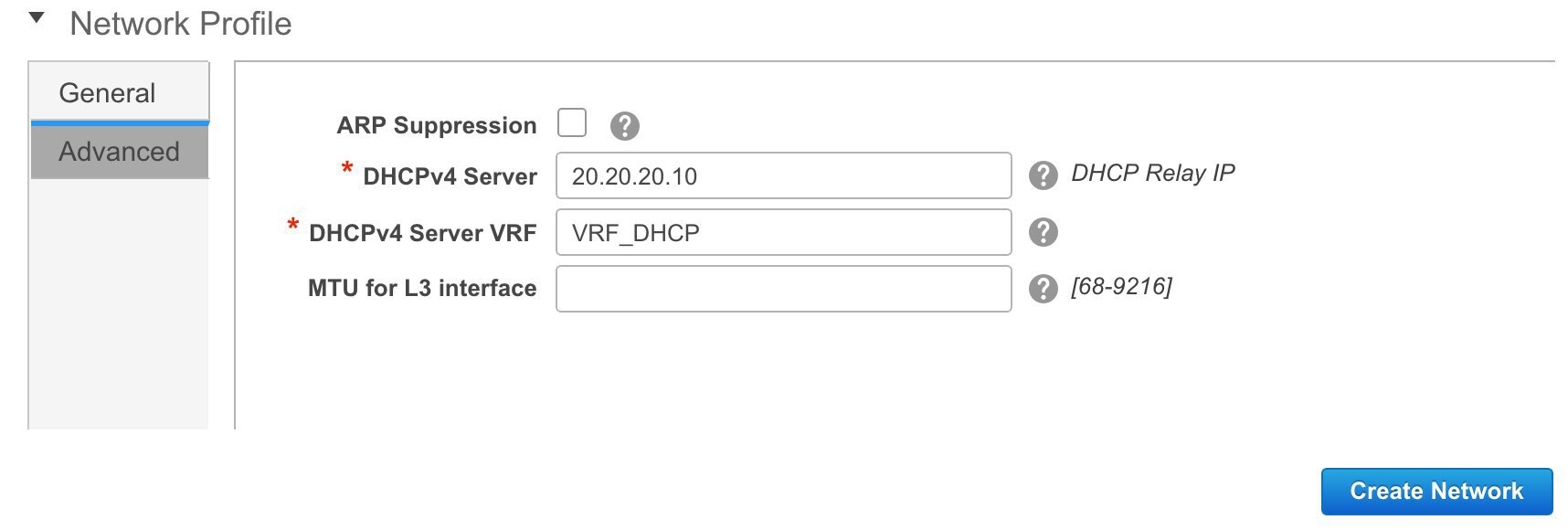
-
-
Click Create Network. A message appears at the bottom right part of the screen indicating that the network is created. The new network (MyNetwork_30000) appears on the Networks page that comes up.
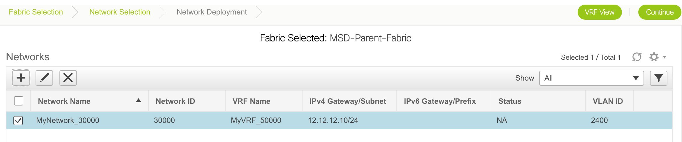
Editing and Deleting Networks in the MSD Fabric
You can edit the Network Profile part (General and Advanced tabs) of the network, including the IPv4 gateway IP address, the DHCP information and the ARP suppression feature.
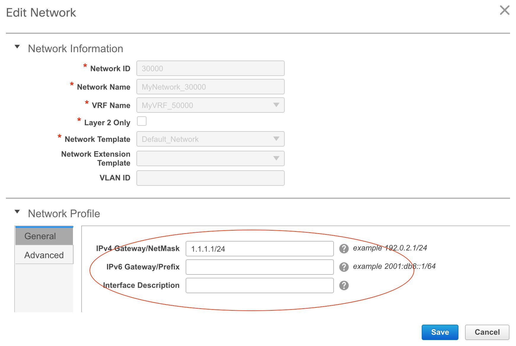
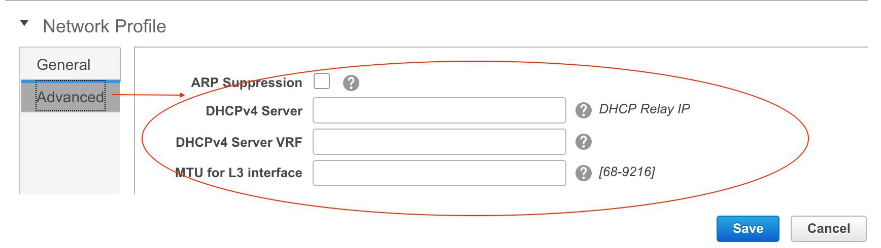
In a standalone fabric, you can proceed to deploy the networks on the fabric's devices. But since this is an MSD container fabric that has no physical devices associated with it, you should deploy the networks through the individual member fabric, for each fabric.
A network or VRF deployed in a member fabric cannot be deleted until all instances are undeployed.
Network Inheritance from MSD-Parent-Fabric to Member1
MSD-Parent-Fabric fabric contains one member fabric, Member1. Go to the Select a Fabric page to access the Member1 fabric.
(To go to the Select a Fabric page do one of the following:
-
Click the Fabric Selection button at the top left part of the screen.
-
From the main menu, click Control > Networks & VRFs and click Continue in the LAN Fabric Provisioning page.
-
Click Member1 from the drop-down box.
-
Click Continue on the top right part of the screen. The Networks page comes up. You can see that the network created for the MSD is inherited to its member.
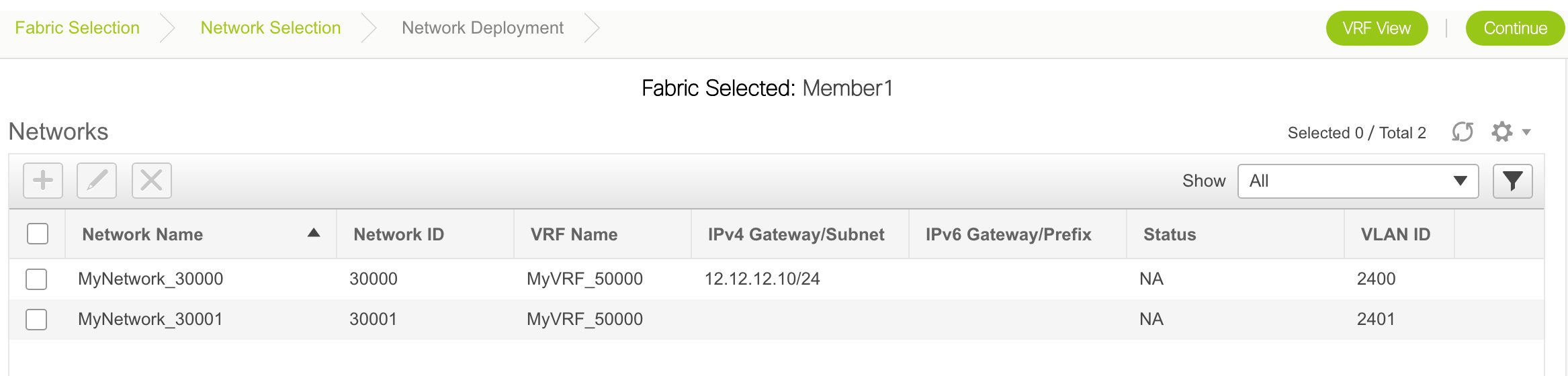
Editing Networks in the Member Fabric
You can only create and delete networks for the MSD fabric, and not for the member fabric. However, you can update a network's multicast group address since it is a fabric instance variable.
-
Select the network and click the Edit option at the top left part of the screen.
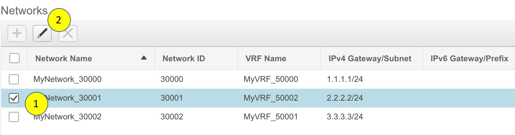
-
In the Edit Networks screen that comes up, click the Advanced tab in the Network Profile section. Update the multicast group address and click Save.
This option is only available for member fabrics and not MSD networks.
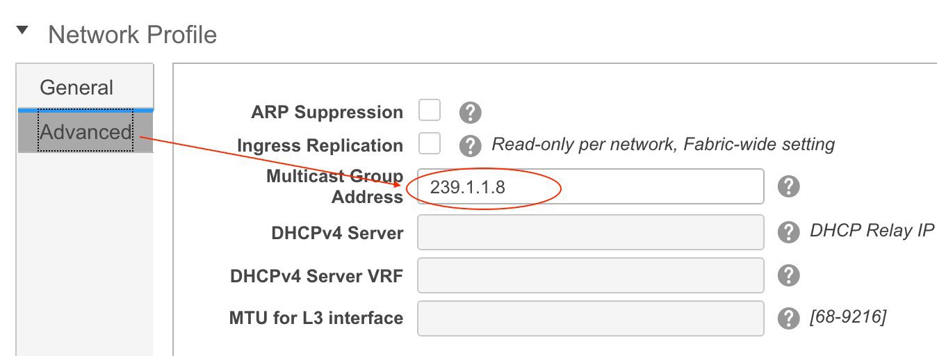
Create VRFs in the MSD Fabric
-
From the MSD fabric's Networks page, click the VRF View button at the top right part of the screen to create VRFs.
[If you have freshly logged in to DCNM, do the following:
Click Control > Networks & VRFs, click Continue in the LAN Fabric Provisioning page and choose the MSD fabric (MSD-Parent-Fabric) from the drop-down box.
Click Continue to reach the Networks page and click VRF View at the top right part of the Networks page].
The VRFs page comes up. This lists the list of VRFs created for the MSD fabric. Initially, this screen has no entries.
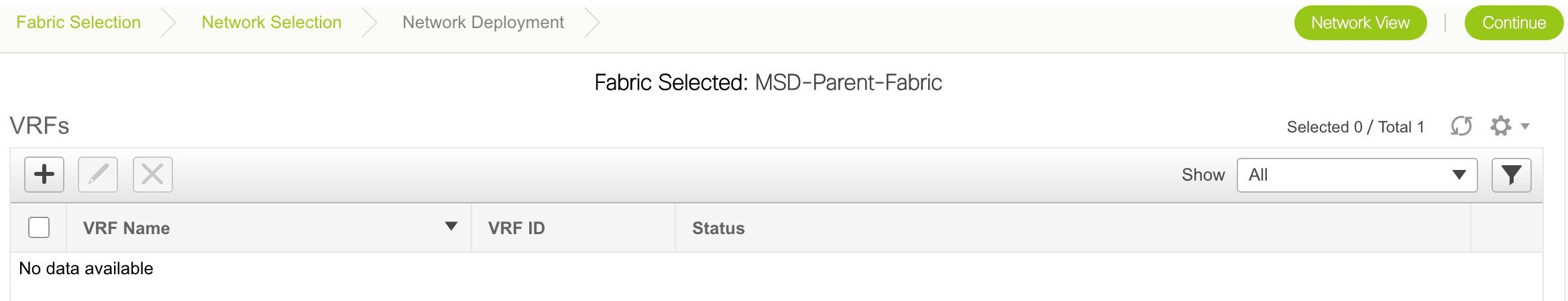
-
Click the + button to add VRFs to the MSD fabric. The Create VRF screen comes up. Most of the fields are autopopulated.

The fields in this screen are:
VRF ID and VRF Name - The ID and name of the VRF.
The VRF ID is the VRF VNI or the L3 VNI of the tenant.
Note
For ease of use, the VRF creation option is also available while you create a network.
VRF Template - This is populated with the Default_VRF template.
VRF Extension Template - This template allows you to extend the VRF between member fabrics.
-
Click Create VRF.
The MyVRF_50000 VRF is created and appears on the VRFs page.
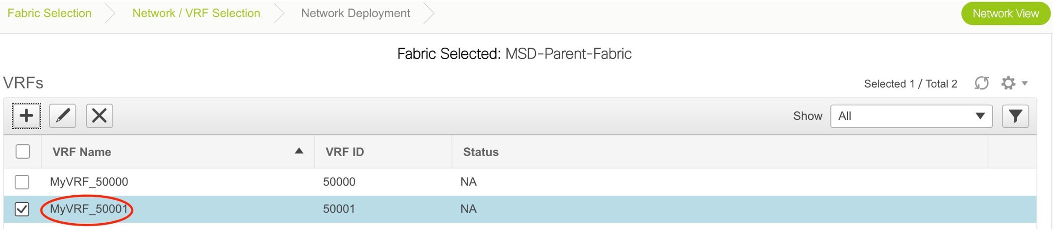
Editing and Deleting VRFs in the MSD Fabric
To delete a VRF, use the delete (X) option at the top left part of the screen. You can delete multiple VRF instances by selecting them and clicking the delete button. You cannot edit VRF parameters after VRF creation.
A network or VRF deployed in a member fabric cannot be deleted until all instances are undeployed.
VRF Inheritance from MSD-Parent-Fabric to Member1
-
MSD-Parent-Fabric contains one member fabric, Member1. Go to the Select a Fabric page to access the Member1 fabric.
[To go to the Select a Fabric page do one of the following:
-
Click the Fabric Selection button at the top left part of the screen.
-
From the main menu, click Control > Networks & VRFs and click Continue in the LAN Fabric Provisioning page].
-
Click Member1 from the drop-down box.
-
Click Continue on the top right part of the screen. The Networks page comes up.
-
Click the VRF View button.
On the VRFs page, you can see that the VRF created for the MSD is inherited to its member.
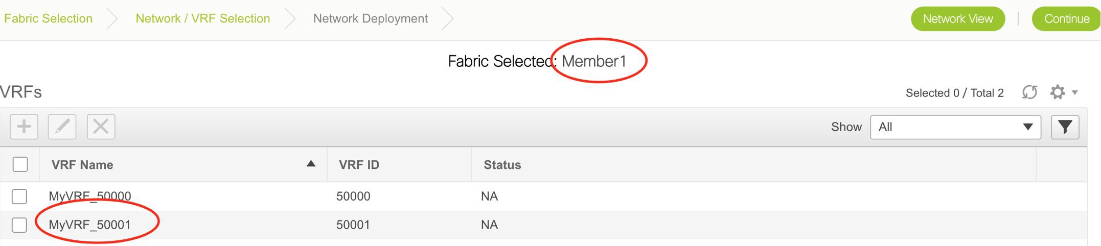
-
Editing and Deleting VRFs in the Member Fabric
You cannot edit VRF parameters or delete a VRF at the member fabric level.
Step 1 of the following is explained. Step 2 information is mentioned in the next subsection.
-
Create networks and VRFs in the MSD fabric.
-
Deploy the networks and VRFs in the member fabric devices, one fabric at a time.
Deployment and Undeployment of Networks and VRFs in Member Fabrics
Before you begin, ensure that you have created networks at the MSD fabric level since the member fabric inherits networks and VRFs created for the MSD fabric.
Note |
The deployment (and undeployment) of networks and VRFs in member fabrics are the same as explained for standalone fabrics. Refer the standalone fabric documentation (Networks Deployment and VRFs Deployment sections in the Networks and VRFs Creation and Deployment in a Standalone Fabric topic). |
Movement of a Standalone Fabric (With Existing Networks and VRFs) to an MSD Fabric
If you move a standalone fabric with existing networks and VRFs to an MSD fabric as a member, ensure that common networks (that is, L2 VNI and L3 VNI information), anycast gateway MAC, and VRF and network templates are the same across the fabric and the MSD. DCNM validates the standalone fabric (network and VRF information) against the (network and VRF information) of the MSD fabric to avoid duplicate entries. An example of duplicate entries is two common network names with a different network ID. After validation for any conflicts, the standalone fabric is moved to the MSD fabric as a member fabric. Details:
-
The MSD fabric inherits the networks and VRFs of the standalone fabric that do not exist in the MSD fabric. These networks and VRFs are in turn inherited by the member fabrics.
-
The newly created member fabric inherits the networks and VRFs of the MSD fabric (that do not exist in the newly created member fabric).
-
If there are conflicts between the standalone and MSD fabrics, validation ensures that an error message is displayed. After the updation, when you move the member fabric to the MSD fabric, the move will be successful. A message comes up at the top of the page indicating that the move is successful.
If you move back a member fabric to standalone status, then the networks and VRFs remain as they are, but they remain relevant as in an independent fabric, outside the purview of an MSD fabric.
NFM Fabric Migration to a DCNM Fabric
NFM VXLAN fabric underlay and overlays can now be migrated and managed in DCNM 11.
Note |
DCNM 10.4(2) release only supported the NFM overlay migrations. |
The migration involves processing the switch configurations and building the intent.
The two use cases involving NFM migration to DCNM are:
-
Migrate an NFM-managed VXLAN BGP EVPN fabric to DCNM 11. Here, the underlay and overlay networks are migrated.
-
Upgrade from DCNM 10.4(2) (or later) with NFM Overlay Migrations to DCNM 11. Here, the underlay is migrated.
Note
This is only applicable to VXLAN BGP EVPN fabrics that were migrated from NFM to DCNM 10.4(2).
Both use cases are explained in this document.
Migrate an NFM-Managed VXLAN BGP EVPN Fabric to DCNM 11
The migration process involves creation of a new VXLAN BGP EVPN fabric through DCNM, adding switches to the fabric for underlay migration and migrating the VXLAN overlay networks from NFM to DCNM.
Prerequisites for NFM Fabric Migration to DCNM
-
Install DCNM 11.0 release software. Refer the relevant Cisco DCNM Installation Guide for more details. Log in to DCNM and set the default LAN Credentials when prompted.
-
Familiarity with the NFM configuration options and screen.
(Go to Switchpool > Settings > Edit. Browse the General and Underlay tabs).
-
Familiarity with the DCNM 11.0 fabric management and monitoring features before initiating the migration process.
-
Familiarity with VXLAN BGP EVPN fabric concepts and functioning of the fabric from the DCNM perspective.
-
Ensure that the NFM fabric switch nodes are operationally stable and functional:
-
All fabric links must be up.
-
vPC switches and the peer links must be up before the migration. Ensure that no configuration updates are in progress or pending changes from NFM.
-
-
Create an inventory list of the switches in the fabric with their IP addresses and credentials. DCNM uses this information to connect to the switches.
-
Open a console session to one of the leaf switches. The session is later used to collect some additional information directly from the switch.
-
Shut down the Cisco NFM software so that it does not make any further configuration changes to the VXLAN fabric. Alternatively, disconnect the NFM network interfaces so that no changes are allowed on the switches.
Guidelines and Limitations
-
Take a backup of the switch configurations and save them before the migration. These configurations can be used to restore the network if necessary.
-
Before starting the process to migrate an NFM-managed VXLAN BGP EVPN fabric to DCNM 11, ensure that there are no configuration inconsistencies, such as inconsistencies in Switch Virtual Interfaces (SVI), VXLAN Network Identifiers (VNI), vPC port channels and so on, in the configurations applied to vPC pair devices.
-
If the NFM-managed switch is not imported into DCNM due to an unknown username or password issue, log in to each switch and specify the username command using the plaintext password. This ensures that the SNMP credentials are set up correctly in NX-OS, and enables DCNM to discover the switch. For example, you can issue this CLI on the switch, where <plaintext password> is the placeholder for entering the plaintext password:
nfm-leaf: snmp-server user admin network-admin auth md5 <plaintext password> -
No configuration changes (unless instructed to do so in this document) must be made to the switches until the migration is completed. Else, significant network issues can occur.
-
Cisco NFM to Cisco DCNM migration is only supported for Cisco Nexus 9000 switches.
-
Before starting the process to migrate an NFM-managed VXLAN BGP EVPN fabric to DCNM 11, ensure that there are no configuration inconsistencies, such as inconsistencies in Switch Virtual Interfaces (SVI), VXLAN Network Identifiers (VNI), vPC port channels and so on, in the configurations applied to vPC pair devices.
-
Fabric point-to-point (P2P) port-channels (between leaf and spine switches) are supported in DCNM 11 only when the NFM fabric being migrated has them. When fabric port channel ports are present, the following guidelines are applicable:
-
Only a single fabric point-to-point port-channel must exist between a leaf switch and spine switch. Multiple fabric port-channels between a leaf switch and spine switch are not supported.
-
Adding or removing links between a leaf switch and spine switch updates the port channel membership automatically.
-
The fabric port channel is deleted when the last member is removed between a leaf switch and spine switch.
-
Adding links after the port channel is deleted makes them standalone point-to-point fabric interfaces.
-
Create a VXLAN BGP EVPN Fabric Through DCNM
A fabric defines a set of devices that makes up the physical fabric, their interconnectivity, configuration, and operational parameters.
-
Click Control > Fabric Builder.
The Fabric Builder page comes up.
-
Click the Create Fabric button. From the Add Fabric screen that comes up, select NFM_Fabric from the Fabric Template drop-down list.
Note
The fabric requires several parameters to be set. Most of the parameters are prepopulated with default values. Carefully review each of the parameters and update them to match your specific fabric requirements.
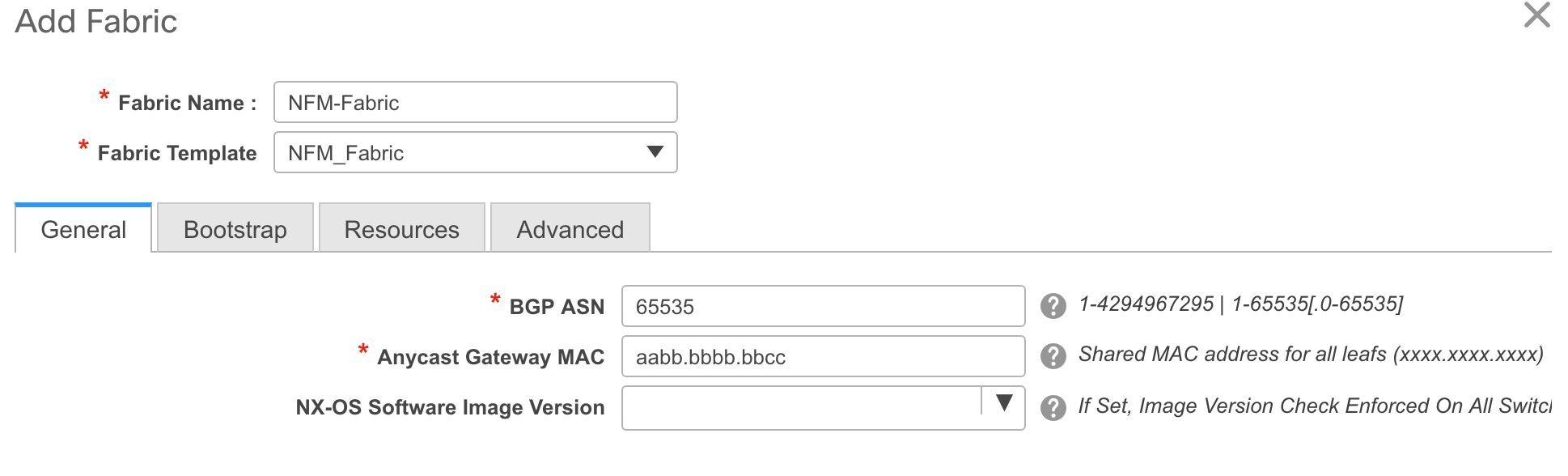
General - The fields on this tab are specific to this fabric.
BGP ASN - Enter the BGP Autonomous System number of the fabric.
Anycast Gateway MAC - Enter the Anycast Gateway MAC address for the fabric.
Note
The MAC address must be of the format xxxx.xxxx.xxxx (for example, ABCD.EF12:3456).
NX-OS Software Image Version - Select an image from the list.
If you upload Cisco NX-OS software images through the image upload option (Control > Image Upload), the uploaded images are listed in this field. If you select an image, the system checks if the switch has the selected version. If not, an error message is displayed. You can resolve the error by clicking on Resolve. The image management screen comes up and you can proceed with the ISSU option. Alternatively, you can delete the release number and save it later.
Bootstrap tab - The fields on this tab are specific to the DCHP settings for the fabric.
Click the Enable DHCP check box to initiate enabling of DHCP for automatic IP address assignment. When you click the check box, the other fields become editable.
Fill up the remaining fields for specifying a DHCP scope for allocating IP addresses to the device interfaces in the fabric. The fields are:
DHCP Scope Start Address and DHCP Scope End Address - The first and last IP addresses of the IP address range.
Switch Management Default Gateway and Switch Management Subnet Prefix - The management gateway IP address and the IP address subnet mask.
Note
DHCP scope and management gateway IP address specification - If you specify the management gateway IP address 10.0.1.0 and subnet mask 24, ensure that the DHCP scope is within the specified subnet, between 10.0.1.1 and 10.0.1.254.
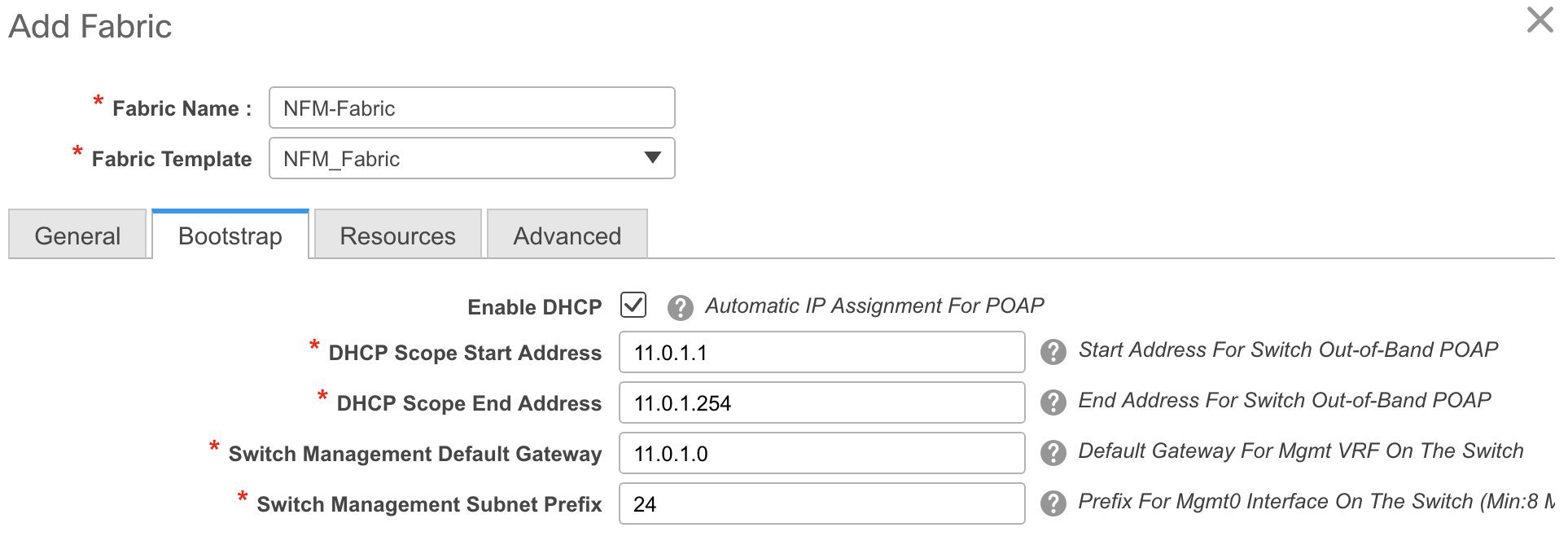
Resources - This tab specifies the IP address, VXLAN VNI, VLAN, and subinterface ranges allocated for the fabric.

Underlay Routing Loopback IP Range - Specifies loopback IP addresses for the protocol peering.
Underlay VTEP Loopback IP Range - Specifies loopback IP addresses for VTEPs.
Underlay Subnet IP Range - IP addresses for underlay P2P routing traffic between interfaces.
Note
NFM uses a single IP underlay address pool. During the DCNM underlay migration, the IP addresses that are found on the switch are honored and retained. However, when any fresh IP address allocation is done after migration, the IP address is picked from the range that is specified here.
Layer 2 VXLAN VNI Range and Layer 3 VXLAN VNI Range - Specifies the VXLAN VNI IDs for the fabric.
Network VLAN Range and VRF VLAN Range - VLAN ranges for the Layer 3 VRF and overlay network.
Subinterface Dot1q Range - Specifies the subinterface range when L3 sub interfaces are used.
Note
These values are defaults. If you want to update the IP address ranges, VXLAN Layer 2/Layer 3 network ID ranges or the VRF/Network VLAN ranges, ensure the following:
-
If you update a range of values, ensure that it does not overlap with other ranges.
-
Update one range of values (L2 Segment ID Range, for example) at a time. If you want to update more than one value, update a specific range, save the changes, and only then update another range of values.
Advanced tab.
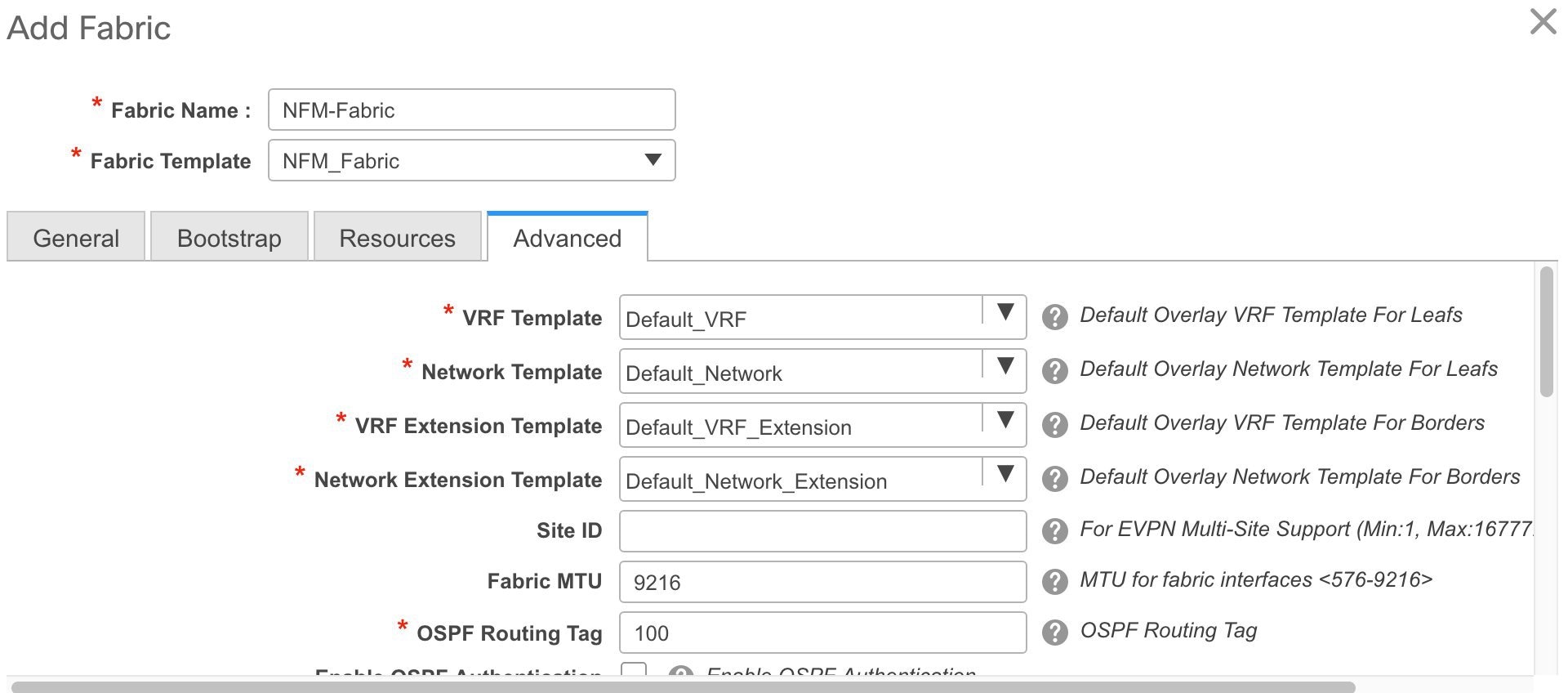
The fields in this tab are:
VRF Template - Specifies the default VRF template for the overlay networks.
Network Template - Specifies the default Network template for the overlay networks.
VRF Extension Template - Specifies the default VRF extension template for extending the overlay networks to other fabrics.
Network Extension Template - Specifies the default Network extension template for extending the overlay networks to other fabrics.
Note
NFM overlay migration supports Default_Network and Default_VRF templates only. Once the fabric has been successfully migrated into DCNM, any of the available templates can be used to deploy new overlay networks.
Site ID - The ID for this fabric if you are moving this fabric within an MSD.
The site ID is mandatory for a member fabric to be a part of an MSD. Each member fabric of an MSD has a unique site ID for identification.
Fabric MTU - Specifies the MTU for the fabric interfaces.
OSPF Routing Tag - Specifies the OSPF routing tag.
Enable OSPF Authentication - Select the check box to enable OSPF authentication. Deselect the check box to disable it.
If you enable this field, the OSPF Authentication Key ID and OSPF Authentication Key fields get enabled.
OSPF Authentication Key ID and OSPF Authentication Key.
Note
The OSPF authentication key must be the 3DES key from the switch. Collect the key ID and the key from one of the leafs.
nfm-leaf# terminal width 300
nfm-leaf# show run ospf | grep message-digest-key
  ip ospf message-digest-key 127 md5 3 c7c83ec78f38f32f3d477519630faf7b
Enable BGP Authentication - Select the check box to enable BGP authentication. Deselect the check box to disable it. If you enable this field, the BGP Authentication Key field gets enabled.
BGP Authentication Key - Enter the 3DES key that is collected from the switch. nfm-leaf# terminal width 300 nfm-leaf# show run bgp | grep password password 3 9e39aa786319a7da1cd23e7dd933e80533b04208805b64077185ecebbcadaa25d791a1d353081e03vPC Peer Link VLAN - VLAN used for the vPC peer link SVI.
For a vPC switch peer link SVI (vlan3966), you must configure these commands manually on each vPC switch. The import fails if you do not configure any of these CLIs or enable additional commands. interface Vlan3966 no shutdown bfd interval 50 min_rx 50 multiplier 3 no bfd echo no ip redirects ip address 172.28.254.30/31 no ipv6 redirects ip router ospf 1 area 0.0.0.0 ip ospf bfdvPC Delay Restore Time - Specifies the vPC delay restore period in seconds.
vPC Auto Recovery Time - Specifies the vPC auto recovery time-out period in seconds.
Power Supply Mode - Choose the appropriate power supply mode.
CoPP Profile - Choose the appropriate Control Plane Policing (CoPP) profile policy for the fabric.
Enable VXLAN OAM - Enables the VXLAM OAM function.
Note
The VXLAN OAM feature in Cisco DCNM is only supported on a single fabric or site.
Enable vPC Advertise PIP - Enables the Advertise PIP feature.
Freeform CLIs - Fabric level freeform CLIs (such as AAA server parameters) can be added while creating or editing a fabric. They are applicable to switches across the fabric. You should add the configurations as displayed in the running configuration, without indentation. Switch level freeform configurations such as VLAN, SVI, and interface configurations should only be added on the switch.
Leaf Freeform Config - Add CLIs that should be added to switches that have the Leaf, Border and Border Gateway roles.
Spine Freeform Config - Add CLIs that should be added to switches with a Spine role.
-
-
Click Save after filing and updating relevant information.
Fabric Underlay Migration
The fabric is placed in a special migration mode when it is created. Several configuration restrictions are in place while the fabric is in this mode. Please ensure the following in this mode:
-
Do not add or edit or delete an interface from the Control > Interfaces page.
-
Do not update switch configurations through the Save & Deploy option (which appears at the top right part of the fabric page).
-
Do not add a new switch (a switch that is not a part of the existing NFM fabric being migrated) through the Add switches or Bootstrap options.
The fabric is automatically taken out of the migration mode when both the underlay and overlay migrations are completed successfully.
Read the following guidelines and then refer the Discovering existing switches section in the Add switches to the fabric topic for detailed migration steps.
-
In the fabric page, use the Add switches option in the Actions panel to add switches to the DCNM-managed fabric.
-
When adding a switch, set Preserve Switch Configuration to Yes.
Use the No setting to add new switches after the underlay and migration is complete.
Note
Adding switches with Preserve Switch Configuration set to No while the fabric is still in the migration state is not supported. Doing so reports an error and the switch is not added to the fabric without making any changes to the switch.
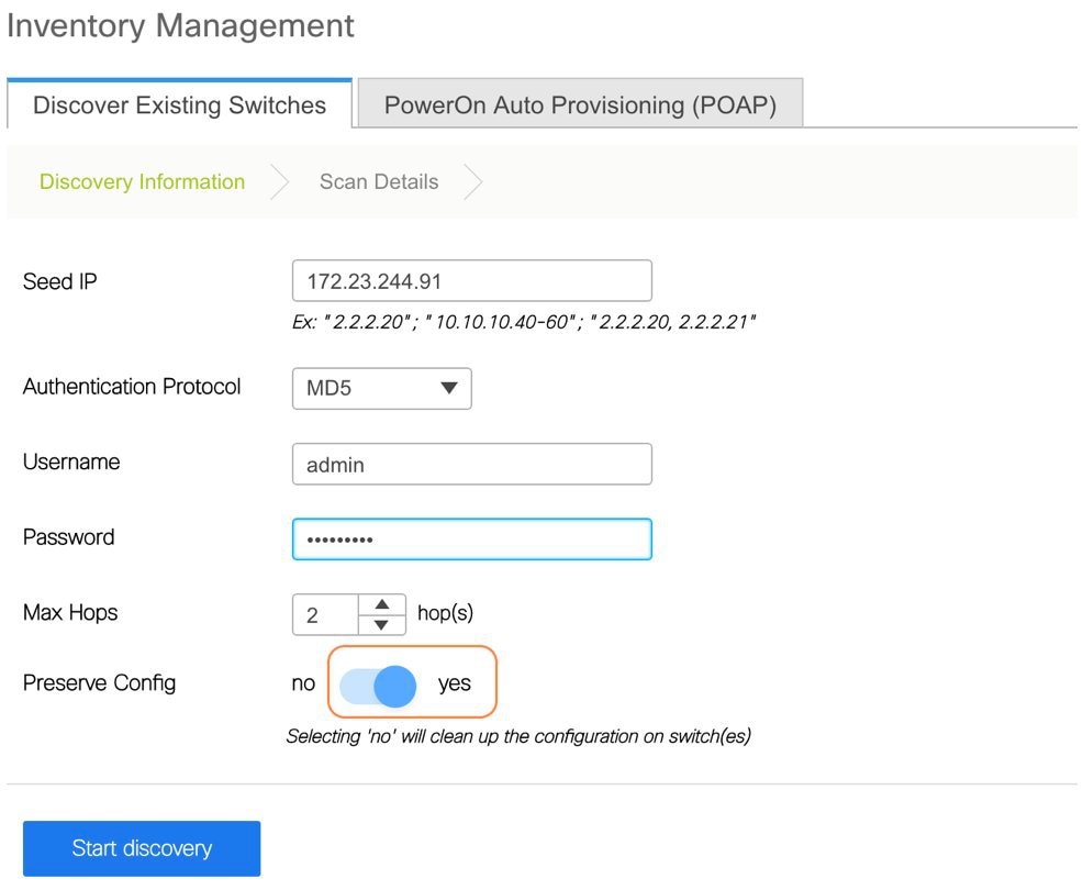
-
Click the Start discovery button and then select the set of switches to be imported from the Inventory Management page that shows up. A progress bar indicates the underlay migration status for each of the switches.
Note
You should not close the Inventory Management page while there are active migrations.
-
The migration workflow will analyse the configurations and the switch is added to the fabric after it passes a set of acceptance criteria. Errors and warnings are reported in the fabric Pending Error as appropriate.
Note
Each switch has a migration mode to track the completion of its underlay migration. A switch in this mode is shown with a special Migration Mode tag in the topology view.
It is normal for a switch to be shown with the tag if an error is detected that prevents the underlay migration to complete. The error message will provide information on the nature of the error and suggested remedial action.
-
Ensure that you add all the NFM fabric devices to the DCNM fabric to complete the underlay migration process. After the underlay networks' migration is complete, the topology is updated in the fabric page.
-
Ensure that the interfaces in the Control > Interfaces screen show the correct policies and associated configurations.
-
You can now proceed to completing the overlay migrations.
Fabric Overlay Migration
The Migration wizard will help you migrate over the NFM Overlay networks (or broadcast domains as known in the NFM). The migration has two phases, Discovery and Migration.
The Discovery phase is where the configurations that are on the switches are parsed and presented in the GUI for review. The networks, interfaces, and switches where the networks exist are displayed. Once you verify the information to be accurate, you can move to the Migration phase by selecting the networks and proceeding to deploy those networks. The GUI workflow tracks the status of the migrations for audit purposes. The migration is considered completed when all the networks are migrated.
Note |
It is important that no configuration or network changes are made to the switches until the migration is completed. Any out-of-band configuration changes can interfere with the migrations and can cause significant network issues. It is important that you verify the discovered networks and data before you initiate a migration. Once the first network is migrated (Migration phase) it is not possible to go back to the Discovery phase to make changes. |
Cisco NFM supports single fabric, whereas Cisco DCNM supports multiple fabrics, so the original NFM-deployed fabric becomes one fabric among all the Cisco DCNM-managed fabrics.
Note |
DCNM 11 currently allows only one active overlay migration to be in progress at a time. |
Each overlay network migration consists of the following steps:
-
Preparing the switch for migration to DCNM Top-Down managed networks.
-
Preparing the Layer 3 network on the switch for migration to DCNM Top-Down managed networks.
-
Deploying the DCNM Top-Down networks configuration to the switch.
-
Removing the original configuration that existed on the switch before the deployment.
Follow these steps to migrate the NFM fabric overlay (networks, VRFs and other overlay parameters) to the DCNM fabric.
-
Click Control > Migration. The Select a Fabric page comes up. The newly created VXLAN fabric appears in the Select a Fabric drop down box.
-
Select the fabric and click Continue on the top right part of the screen.
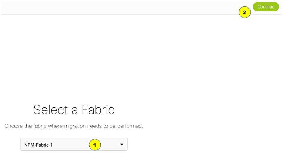
The NFM fabric migration page comes up.
To start with, the DISCOVERY IN PROGRESS message appears at the top of the Migration screen. The discovery process auto-generates the network name of the form as Auto_Net_VLANxxx_VNIyyyyy.
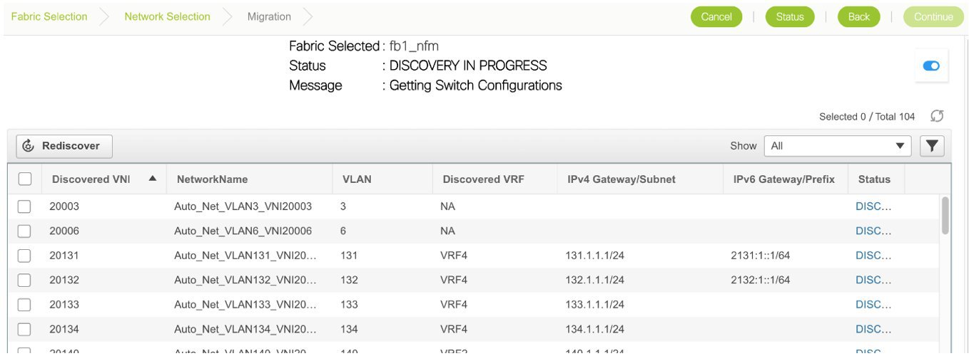
Cisco DCNM will retrieve the running configuration from the switches, parse the configurations to discover the VXLAN overlay data. At this point, the migration is considered to be in progress.
The parsing occurs in the background and the page refreshed with the discovered networks. You cannot proceed further until the discovery process is completed. The Continue button and the check boxes are disabled while discovery is in progress. The discovered networks are persisted until one of the following events occurs:
-
Migration is completed (network is deployed and the original configuration CLIs are removed).
-
Until you click the Rediscover button upon which the current list is discarded and configuration is parsed again. The Rediscover button will throw an error once the migration status is changed to MIGRATION IN PROGRESS. The only time a Rediscovery can be performed is when the status is DISCOVERY COMPLETED. The other states where the Rediscover can be triggered are DISCOVERY FAILED and DISCOVERY ABORTED.
-
Until you cancel the migration.
After the discovery process is complete, the DISCOVERY COMPLETED message appears at the top of the screen.
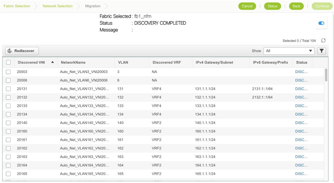
Note
It is important that the discovered networks and data is verified before a migration is attempted. Make necessary changes and click Rediscover to restart the discovery process.
At any point in time, click Cancel to cancel the discovery process that is in progress and click the Status button to view the status.
-
-
After the discovery process is completed, select the networks that you want to migrate to the DCNM fabric.
-
Click Continue at the top right part of the screen. The page that appears next has some additional options that allow you to preview existing configurations and the configurations that are going to be deployed on the switches.
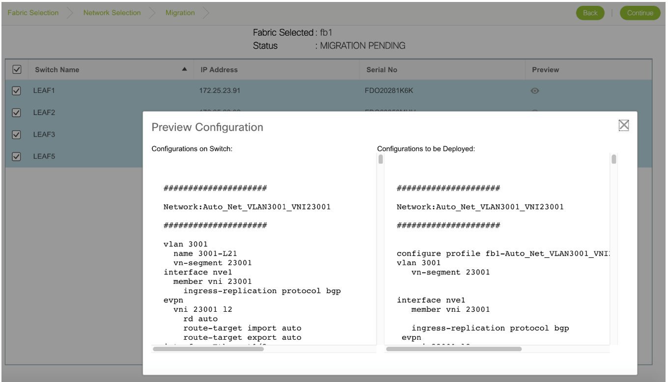
You can select the switch(es) where the networks needs to be migrated. It is however recommended to select all the switches for the migration. If only a subset of switches is selected, ensure that both the switches in the vPC pair are present.
After the overlay network migration is completed, a message MIGRATION COMPLETED is displayed at the top of the screen.
The fabric is moved out of the migration mode and the complete DCNM 11 fabric management functions are enabled.
Viewing Overlay Migration Status
In the Migration page, click the Status button. The page that appears reports the cumulative status of all migrations performed so far.
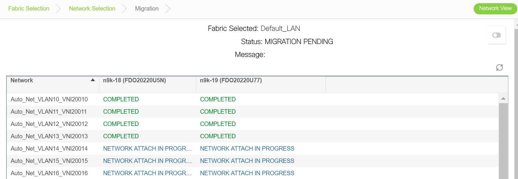
You can click the hyperlinks to view migration history and status.
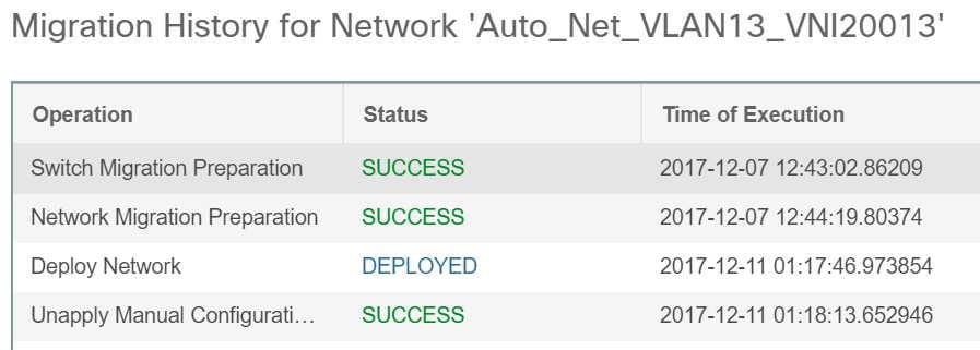
Troubleshooting Cisco NFM to Cisco DCNM Migration
The Migration workflow involves multiple steps and some unexpected issues that you might encounter while migrating Cisco NFM to Cisco DCNM. Fabric underlay and overlay examples:
Fabric Underlay Troubleshooting
Errors and warnings reported during the underlay operations are reported in the fabric Pending Errors, at the top right part of the screen.
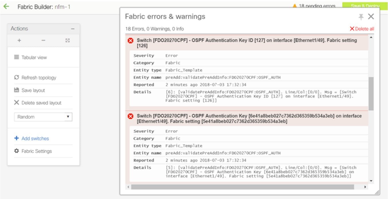
Fabric Overlay Troubleshooting
An issue encountered during the overlay migration will fail the process with an appropriate FAILED status and the Message field will indicate the failure.
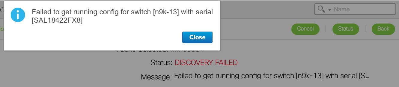
Network Migration Failures
Go to the migration page, identify the network and switch that has encountered the failure and click the Status hyperlink. The resulting popup shows the status of each migration step.
Further details can be obtained by clicking the appropriate hyperlinks and additional details can be obtained by reviewing the log files.
Migration Workflow Failures
The migration status will indicate a FAILURE. Additional details can be obtained by reviewing the log files.
Migration Workflow Status Definitions
This section describes the various states for the discovery or migration workflow:
Discovery-related Status Definitions
DISCOVERY INITIATED - A discovery has been triggered and waiting to start.
DISCOVERY IN PROGRESS - The discovery is active.
DISCOVERY FAILED - The previous discovery failed.
DISCOVERY ABORT INITIATED - An attempt to cancel an active discovery has been initiated.
DISCOVERY ABORTED - The previous discovery has been canceled.
DISCOVERY COMPLETED - The discovery has been completed successfully.
Migration-related Status Definitions
MIGRATION INITIATED - Migration has been initiated for a set of networks.
MIGRATION IN PROGRESS - Migration is in progress for a set of networks.
MIGRATION FAILED - The previous migration failed.
MIGRATION ABORT INITIATED - An attempt to cancel an active migration has been initiated.
MIGRATION ABORTED - Migration has been canceled.
MIGRATION PENDING - There are more networks waiting to be migrated.
MIGRATION COMPLETED - All the networks have been migrated.
Network Migration Status Definitions
DISCOVERED - The network has been discovered from the switch configurations.
SWITCH MIGRATION PREPARATION IN PROGRESS - The switch where the network is present is being prepared.
SWITCH MIGRATION PREPARATION FAILED - The switch preparation step failed.
NETWORK MIGRATION PREPARATION IN PROGRESS - The L3 network is being prepared for migration.
NETWORK MIGRATION PREPARATION FAILED - The L3 network preparation step failed.
NETWORK CREATION IN PROGRESS - The LAN Fabric Provisioning Network entry is being created.
NETWORK CREATION FAILED - The LAN Fabric Provisioning Network entry creation failed.
NETWORK DEPLOYMENT IN PROGRESS - The LAN Fabric Provisioning Network deployment is in progress.
NETWORK DEPLOYMENT FAILED - The LAN Fabric Provisioning Network deployment failed.
ORIGINAL CONFIGURATION REMOVAL PENDING - The LAN Fabric Provisioning Network deployment is successful and waiting to remove the original NFM configured CLIs.
ORIGINAL CONFIGURATION REMOVAL IN PROGRESS - The removal of the original NFM configured CLIs is in progress.
ORIGINAL CONFIGURATION REMOVAL RECOVERABLE FAILURE - The removal of the original NFM configured CLIs failed, but, can be retried on a future attempt after fixing any underlying issues.
ORIGINAL CONFIGURATION REMOVAL FAILED - The removal of the original NFM configured CLIs failed. The failure reason must be reviewed and manual corrective action must be taken. Please review the nature of the failure(s). If some of the configuration CLIs were partially applied, please reapply the failed and rest of the CLIs manually on the switch(es).
COMPLETED - The network was migrated successfully.
Network Migration History Definitions
Switch Migration Preparation - Provides status of preparing the switch for the migration. This action is performed only once per switch, but, will show up in all network histories.
Network Migration Preparation - Provides status of the network migration preparations. This entry is only present for L3 networks.
Deploy Network - Provides status of the LAN Fabric Network provisioning.
Unapply Manual Configurations - Provides status of removing the network overlay CLIs configured by NFM. Note that this does not lead to any loss of configuration since LAN Fabric Provisioning uses configuration profiles.
Upgrade from DCNM 10.4(2) with NFM Overlay Migrations to DCNM 11
Note |
The explanation is only applicable to VXLAN fabrics that were migrated from NFM to DCNM 10.4(2) or later. |
-
Follow the recommended DCNM upgrade procedure and upgrade to DCNM 11.
-
After DCNM is reachable, click Control > Fabric Builder.
The fabrics are listed in a distinct color.
-
Identify the NFM fabric and click Edit. Select the NFM fabric from the Fabric Template drop-down box. Many of the fabric settings have default values. Review all the settings to make sure that they match your fabric. Refer to the Create a VXLAN BGP EVPN Fabric Through DCNM section for information on the fabric settings.
-
Click Save at the bottom right part of the screen. All the switches are displayed with the Migration Mode tag.
-
Click Save & Deploy to complete the migration of the underlay networks .
-
The overlay networks do not need any additional migration action.
Post Migration Operations
After completing the underlay and overlay migrations, follow these steps:
-
Navigate to Control > Fabric Builder in the DCNM GUI. On the page that comes up, click the fabric. The fabric topology page comes up.
-
Click Save & Deploy. This step implements the DNCM 11 VXLAN BGP EVPN fabric best practice of deploying all pending configurations on the fabric switches.
Note
Review the configuration differences that show up, for accuracy, before deploying them to the switch.
Now the fabric is ready for use.
Updating Switch Level Settings
A few switch level settings can be updated using this procedure:
-
Navigate to Control > Fabric Builder and select the fabric.
-
Right click the switch to update its settings, and click the View/Edit Policies option and do the following:
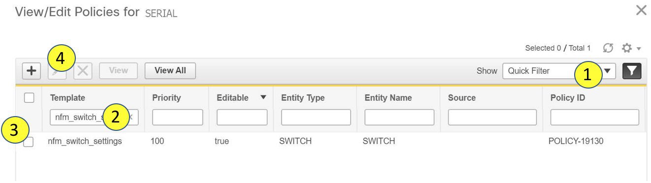
-
Enable the filtering option (at the top right part of the screen) and enter nfm_switch_settings in the Template field.
-
Select the nfm_switch_settings policy and click Edit. The Edit Policy screen comes up.
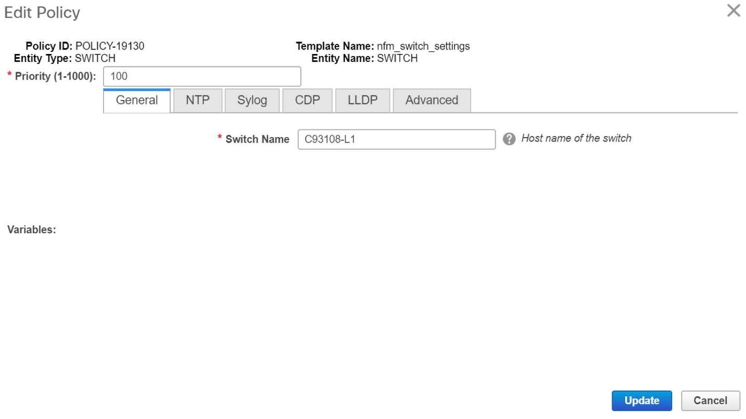
-
Make changes and click Update to update the settings.
-
A Save & Deploy pushes these configuration changes to the switch.
-
Updating Fabric OSPF Authentication Parameters
Disabling OSPF Authentication
-
Navigate to Control > Fabric Builder and click the settings icon of the fabric. The Edit Fabric screen comes up.
-
Click the Advanced tab and deselect the Enable OSPF Authentication check box.
-
Click Save.
-
A Save & Deploy pushes these configuration changes to the switch.
Note |
The task can cause traffic disruption. |
Enabling or Updating OSPF Authentication
-
Log in to one of the leaf switches in the fabric and collect the following information:
nfm-leaf(config)# interface loopback 999 [Pick a non-existent loopback id]

nfm-leaf(config-if)# ip ospf message-digest-key 127 md5 testPassword [Use the desired key ID and password]
nfm-leaf(config-if)# show run interface lo999 interface loopback999 ip ospf message-digest-key 127 md5 3 1afc85c3227850739fff5d727ad413f6nfm-leaf(config-if)# no interface lo999 [delete the temporary loopback interface created earlier] -
Navigate to Control > Fabric Builder and click the settings icon of the fabric. The Edit Fabric screen comes up.
-
Click the Advanced tab and select the Enable OSPF Authentication check box if not already selected.
-
From the information that is collected earlier, enter the key ID into the OSPF Authentication Key ID field and the 3DES key as-is into the OSPF Authentication Key field.
-
Click Save.
-
A Save & Deploy pushes these configuration changes to the switch.
Note |
The task can cause traffic disruption. |
Updating Fabric BGP Authentication Parameters
Disabling BGP Authentication
-
Navigate to Control > Fabric Builder and click the settings icon of the fabric. The Edit Fabric screen comes up.
-
Click the Advanced tab and deselect the Enable BGP Authentication check box.
-
Click Save.
-
A Save & Deploy pushes these configuration changes to the switch.
Note |
The task can cause traffic disruption. |
Enabling or Updating BGP Authentication
-
Log in to one of the leaf switches in the fabric and collect the following information:
nfm-leaf# conf t
nfm-leaf(config)# router bgp <bgp as #>     [BGP AS Number]
nfm-leaf(config-router)# neighbor 1.1.1.1   [A non existent BGP neighbor ID]
nfm-leaf(config-router-neighbor)# password testPassword [desired password in cleartext]nfm-leaf(config-router-neighbor)# show run bgp [snip] router bgp <bgp as #> [snip] neighbor 1.1.1.1 password 3 f092f5f76d298504ca9b1ad0f1469ca8nfm-leaf(config-router-neighbor)# exit nfm-leaf(config-router)# no neighbor 1.1.1.1 [delete the neighbor created earlier ] -
Navigate to Control > Fabric Builder and click the settings icon of the fabric. The Edit Fabric screen comes up.
-
Click the Advanced tab and select the Enable BGP Authentication check box, if already not selected.
-
From the information that is collected earlier, enter the highlighted 3DES key as-is into the BGP Authentication Key field.
-
Click Save.
-
A Save & Deploy pushes these configuration changes to the switch.
Note |
The task can cause traffic disruption. |
Freeform Configurations on Fabric Switches
In DCNM, you can add custom configurations through freeform policies in the following ways:
-
Fabric-wide
-
On all leaf and border switches in the fabric, at once.
-
On all spine switches, at once.
-
-
On a specific switch.
Leaf switches are identified by the role Leaf, border switches by the role Border or Border-Gateway and spine switches by the role Spine.
Note |
You can deploy freeform CLIs when you create a fabric or when a fabric is already created. The following examples are for an existing fabric. However, you can use them as a reference for a new fabric. |
Deploy Fabric-Wide Freeform CLIs on Leaf and Spine Switches
-
Click Control > Fabric Builder. The Fabric Builder screen comes up. A rectangular box represents each fabric.
-
Click the Settings icon (located on the top right part of the rectangular box) for adding custom configurations to an existing fabric. The Edit Fabric screen comes up.
(If you are creating a fabric for the first time, click Create Fabric).
-
Click the Advanced tab and update the following fields:
Leaf Freeform Config – In this field, add configurations for all leaf and border switches in the fabric. For example, you can add NTP, TACAS, and AAA configurations in this field.
Don’t add VLAN, SVI, and interface-specific configurations.
Spine Freeform Config - In this field, add configurations for all spine switches in the fabric.
Note
Copy-paste the intended configuration with correct indentation, as seen in the running configuration on the Nexus switches. For more information, see Resolving Freeform Config Errors in Switches.
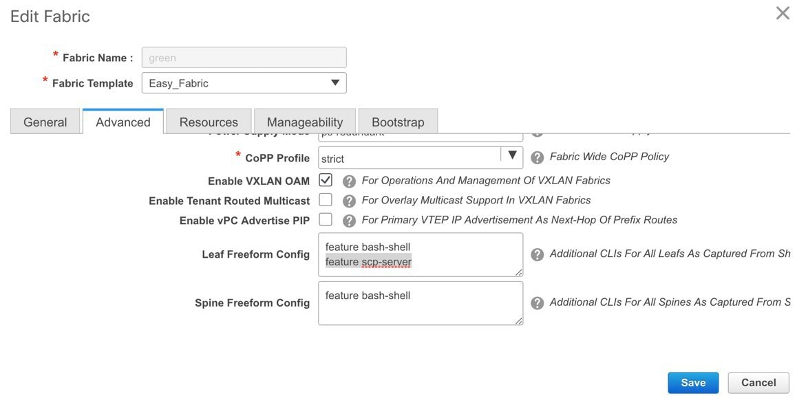
-
Click Save. The Fabric Builder screen comes up again.
-
Click within the box that represents the fabric. The Fabric Topology screen comes up.
-
Click Save & Deploy at the top right part of the screen to save and deploy configurations.
Configuration Compliance functionality will ensure that that intended configuration as expressed by those CLIs are present on the switches and if they are removed or there is a mismatch, then it will flag it as a mismatch and indicate that the device is OUT-OF-SYNC.
Incomplete Configuration Compliance - On some Cisco Nexus 9000 Series switches, in spite of configuring pending switch configurations using the Save & Deploy option, configuration compliance is not successful. Add a switch_freeform_config policy to the affected switch (as explained in the Deploy Freeform CLIs on a Specific Switch section) to resolve the issue. For example, consider the following persistent pending configurations:
line vty
logout-warning 0
After adding the above configurations in a switch_freeform_config policy and saving the updates, click Save and Deploy in the topology screen to complete the deployment process.
Deploy Freeform CLIs on a Specific Switch
-
Click Control > Fabric Builder. The Fabric Builder screen comes up.
-
Click on the rectangular box that represents the fabric. The Fabric Topology screen comes up.
Note
To provision freeform CLIs on a new fabric, you have to create a fabric, import switches into it, and then deploy freeform CLIs.
-
Right-click the switch icon and select the View/edit policies option.
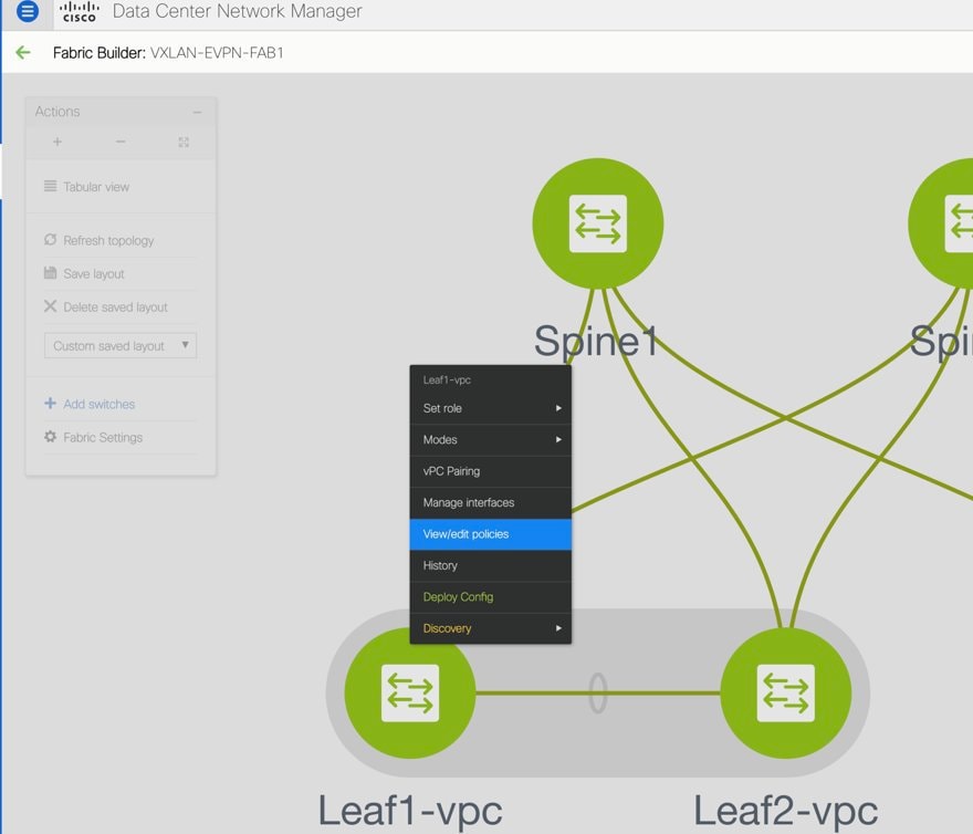
The View/Edit Policies screen comes up.
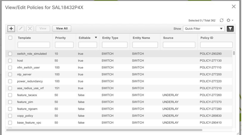
-
Click +. The Add Policy screen comes up.
In the Priority field, the priority is set to 500 by default. You can choose a higher priority (by specifying a lower number) for CLIs that need to appear higher up during deployment. For example, a command to enable a feature should appear earlier in the list of commands.
-
From the Policy field, select switch_freeform_config.
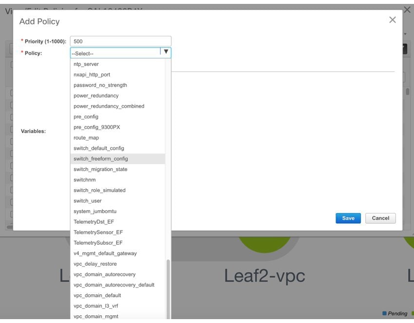
-
Add or update the CLIs in the Freeform Config CLI box.
Copy-paste the intended configuration with correct indentation, as seen in the running configuration on the Nexus switches. For more information, see Resolving Freeform Config Errors in Switches.
A switch_freeform_config policy example for VLAN and corresponding SVI instantiation is given below.
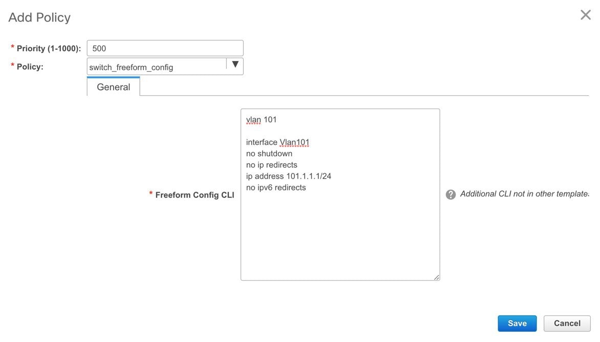
-
Click Save.
After the policy is saved, it gets added to the intended configurations for that switch.
-
Close the policy screens. The Fabric Topology screen comes up again.
-
Right click the switch and click Deploy Config.
The Save & Deploy option can also be used for deployment. However, the Save & Deploy option will identify mismatch between the intended and running configuration across all fabric switches.
Pointers for switch_freeform_config Policy Configuration:
-
You can create multiple instances of the policy.
-
You can add VLAN, SVI and other features. A specific VLAN and corresponding SVI instantiation should be configured through an individual switch_freeform_config policy.
-
For a vPC switch pair, create consistent switch_freeform_config policies on both the vPC switches.
-
Depending on the Cisco Nexus 9000 Series platform type (required for EX, FX, and FX2 platform types), you should include the system nve infra-vlans 101 command in the policy.
Freeform CLI Configuration Examples
Note |
Refer the Deploy Fabric-Wide Freeform CLIs on Leaf and Spine Switches section and Deploy Freeform CLIs on a Specific Switch section for complete steps. |
Console line configuration
This example involves deploying some fabric-wide freeform configurations (for all leaf, and spine switches), and individual switch configurations.
Fabric-wide session timeout configuration:
line console
  exec-timeout 1
Console speed configuration on a specific switch:
line console
  speed 115200
On the switch where the console speed was updated, both types of configurations are displayed:
N9k-switch # show run | b console

line console
  exec-timeout 0
  speed 115200
ACL configuration
ACL configurations are typically configured on specific switches and not fabric-wide (leaf/spine switches). When you configure ACLs as freeform CLIs on a switch, you should include sequence numbers. Else, there will be a mismatch between the switch and DCNM. A configuration sample with sequence numbers:
ip access-list ACL_VTY
  10 deny tcp 172.29.171.67/32 172.29.171.36/32
  20 permit ip any any
ip access-list vlan65-acl
  10 permit ip 69.1.1.201/32 65.1.1.11/32
  20 deny ip any any

interface Vlan65
  ip access-group vlan65-acl in
line vty
  access-class ACL_VTY in
If you have configured ACLs without sequence numbers in a switch_freeform_config policy, update the policy with sequence numbers as displayed in the switch. After updating, use the per switch Deploy Config option by right clicking the device. Alternatively, use the Save and Deploy option in the topology screen so that configuration compliance is triggered again and inconsistencies resolved.
Negotiation, speed and duplex port configuration
Consider the following commands configured on a leaf switch whose Ethernet1/10 interface is connected to a spine switch. The ethernet port speed, duplex mode and disabling of automatic negotiation of speed and duplex abilities over the link are configured for the interface.
interface Ethernet1/10
   speed 100000
   duplex full
   no negotiate auto
This can be configured as a switch_freeform_config policy on a switch.
If the above parameters are the same for all leaf switches (interface 1/10 on each leaf switch has the same settings and connected to a switch), then you can update fabric-wide CLIs for all leaf switches.
In the same way, you can configure all spine switches with the same port name and speed, duplex mode and negotiation settings.
Note |
If you are enabling freeform configurations on all leaf or spine switches, as a best practice, ensure that all switches are connected through the same type of cable. For example, Active Optical Cables or Direct Attach Copper cables. |
Resolving Freeform Config Errors in Switches
Copy-paste the running-config to the freeform config with correct indentation, as seen in the running configuration on the NX-OS switches. The freeform config must match the running config. Otherwise, configuration compliance in DCNM marks switches as out-of-sync.
Let us see an example of the freeform config of a switch.
feature bash-shell
feature telemetry

clock timezone CET 1 0
# Daylight saving time is observed in Metropolitan France from the last Sunday in March (02:00 CET) to the last Sunday in October (03:00 CEST)
clock summer-time CEST 5 Sunday March 02:00 5 Sunday October 03:00 60
clock protocol ntp

telemetry
  destination-profile
    use-vrf management
The highlighted line about the daylight saving time is a comment that is not displayed in the show running config command output. Therefore, configuration compliance marks the switch as out-of-sync because the intent does not match the running configuration.
Let us check the running config in the switch for the clock protocol.
spine1# show run all | grep "clock protocol"
clock protocol ntp vdc 1
You can see that vdc 1 is missing from the freeform config.
In this example, let us copy-paste the running config to the freeform config.
Here is the updated freeform config:
feature bash-shell
feature telemetry

clock timezone CET 1 0
clock summer-time CEST 5 Sunday March 02:00 5 Sunday October 03:00 60
clock protocol ntp vdc 1

telemetry
  destination-profile
    use-vrf management
After you copy-paste the running config and deploy, the switch will be in-sync. When you click Save & Deploy, the Side-by-side Comparison tab in the Config Preview window provides you information about the difference between the defined intent and the running config.
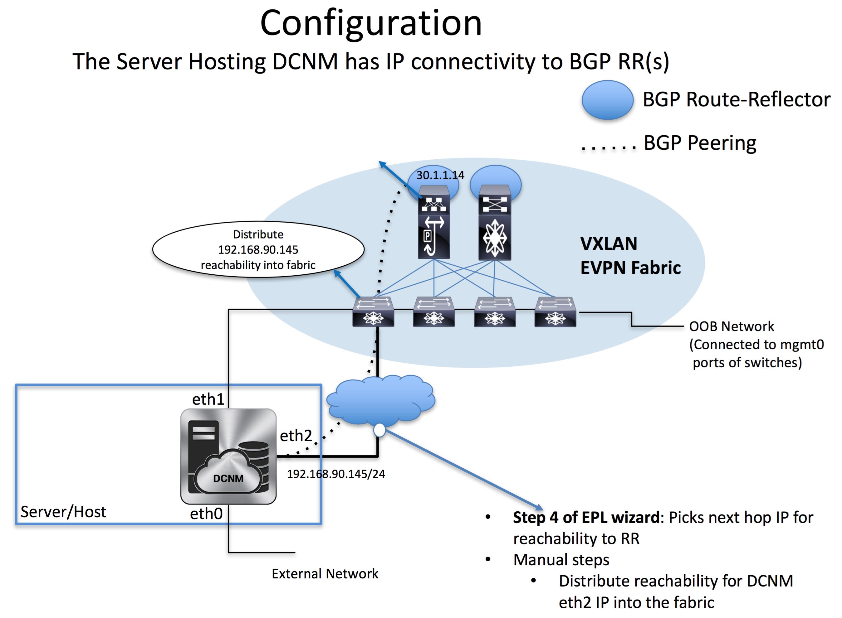
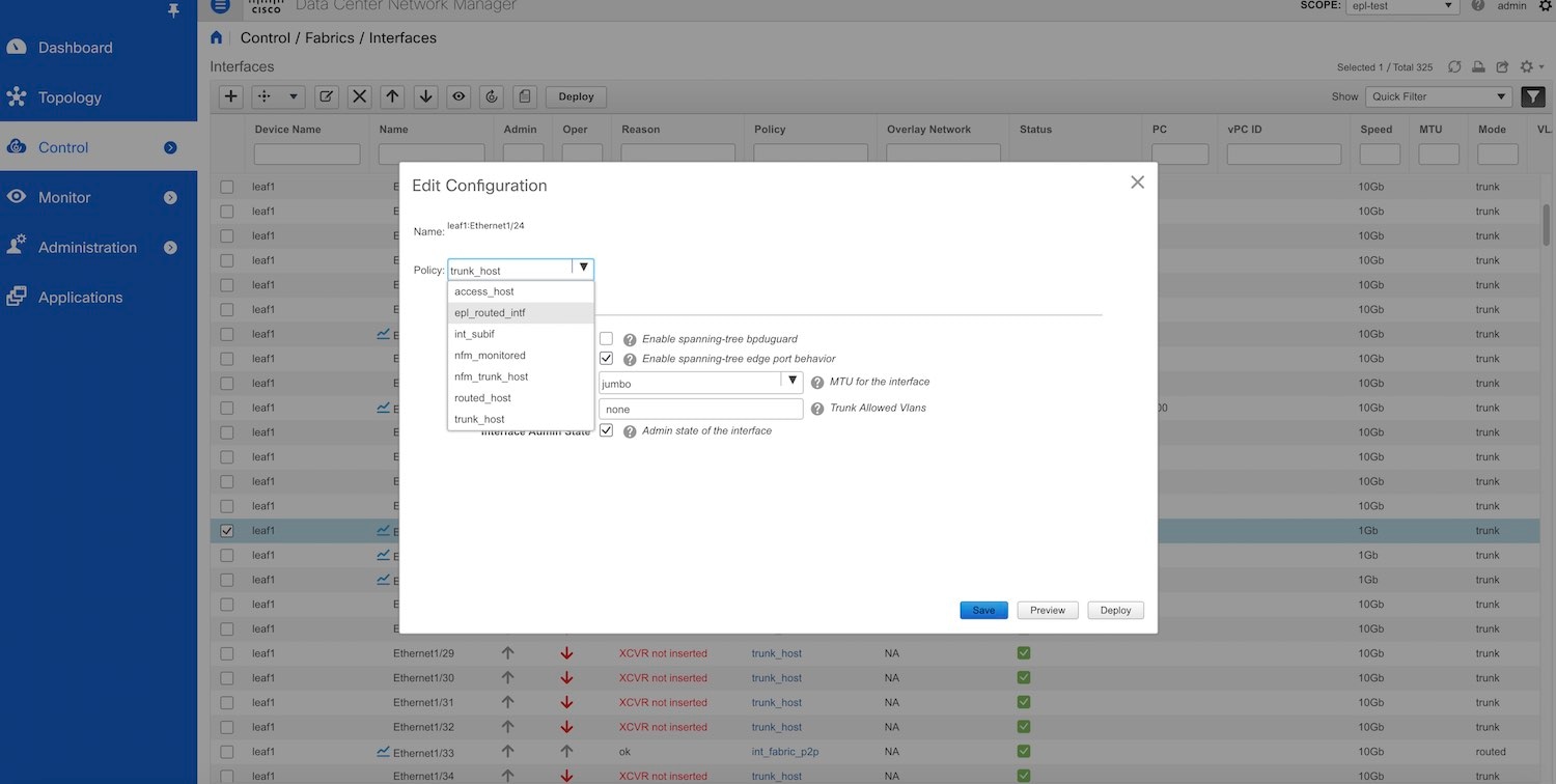
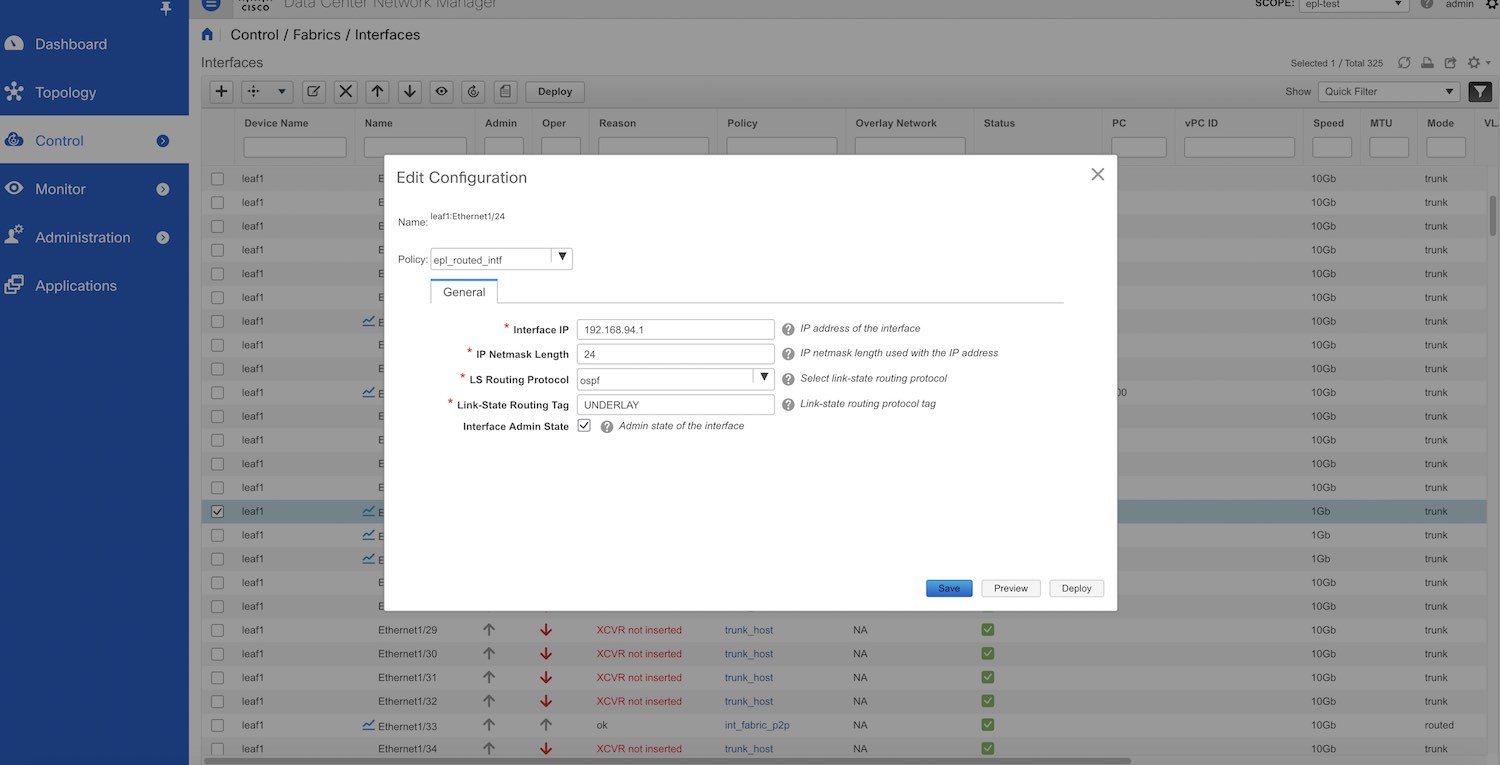
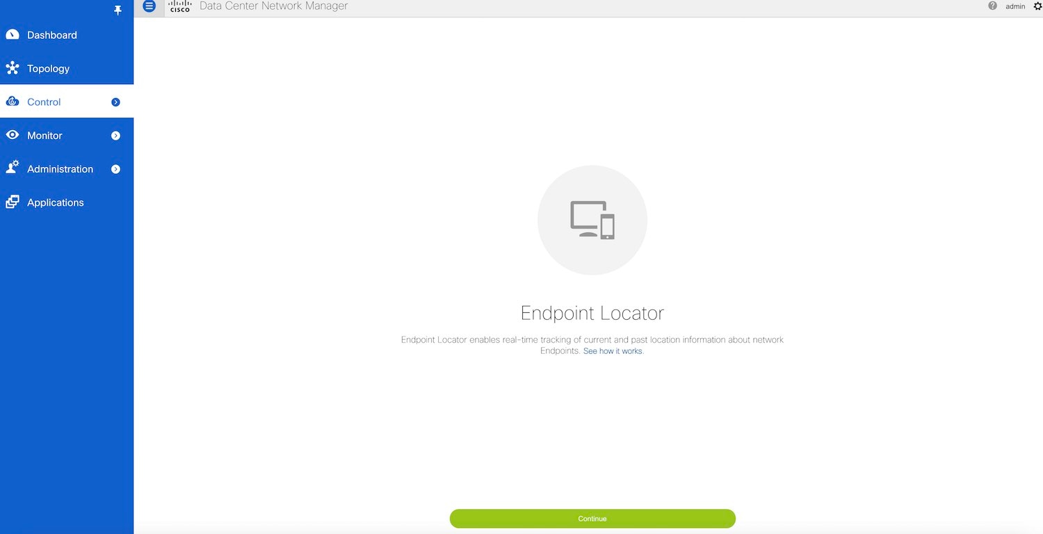
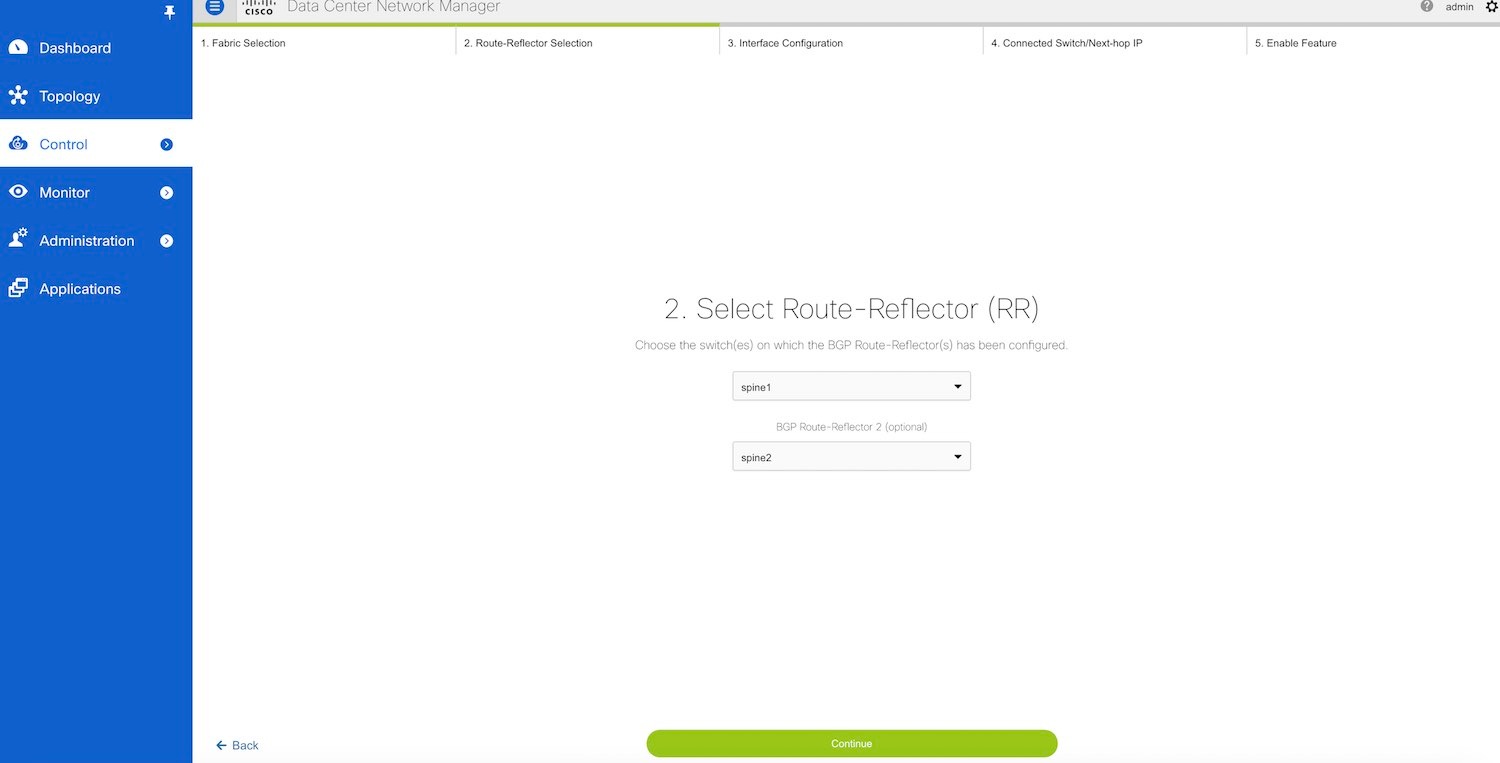
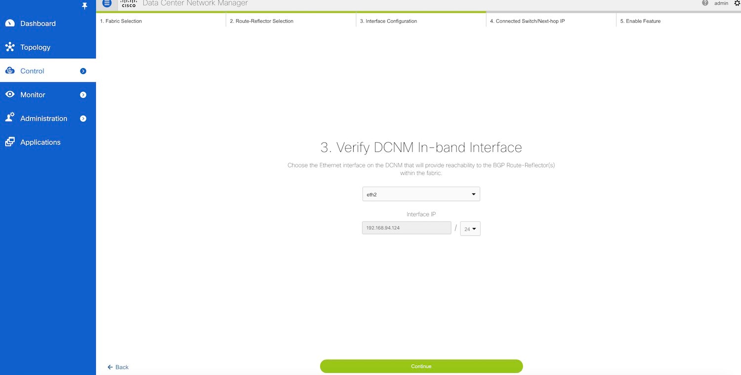

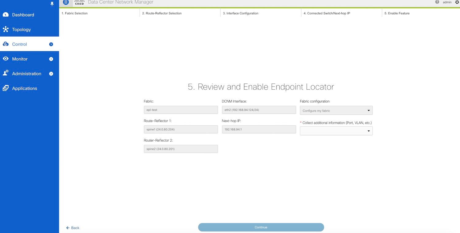
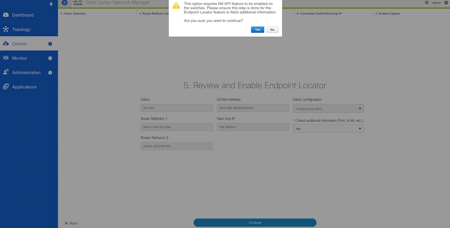
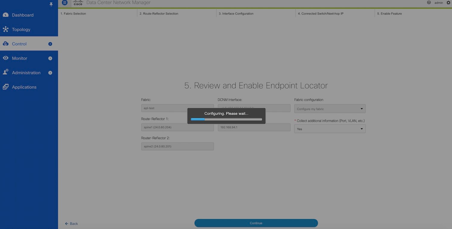
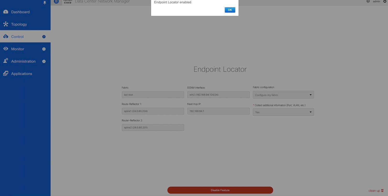
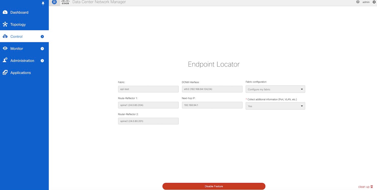
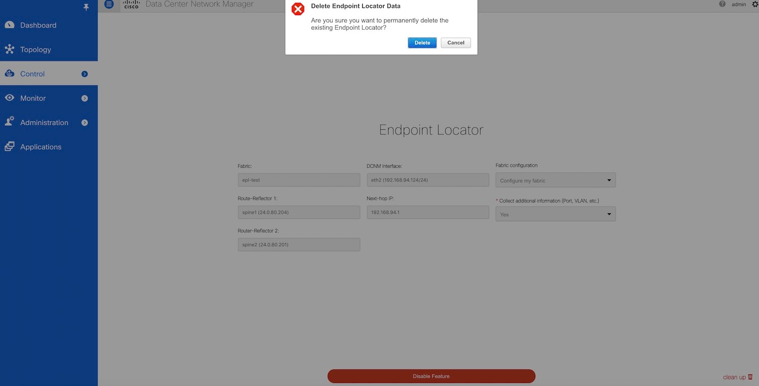
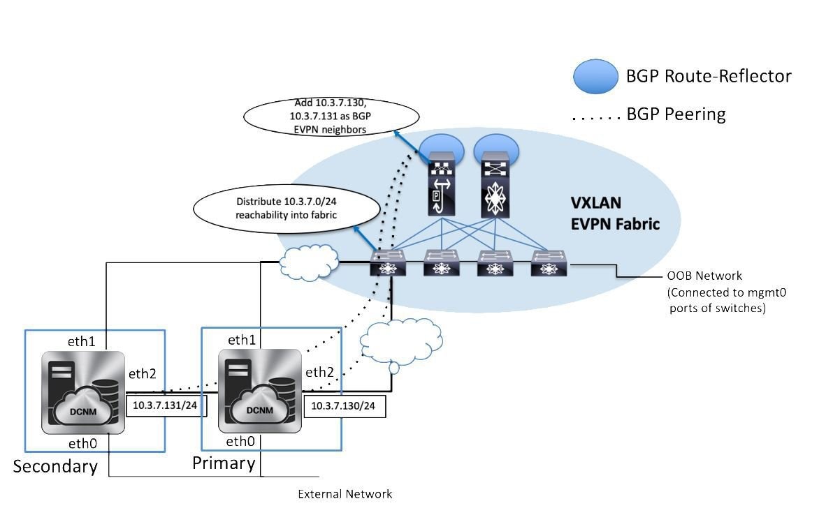
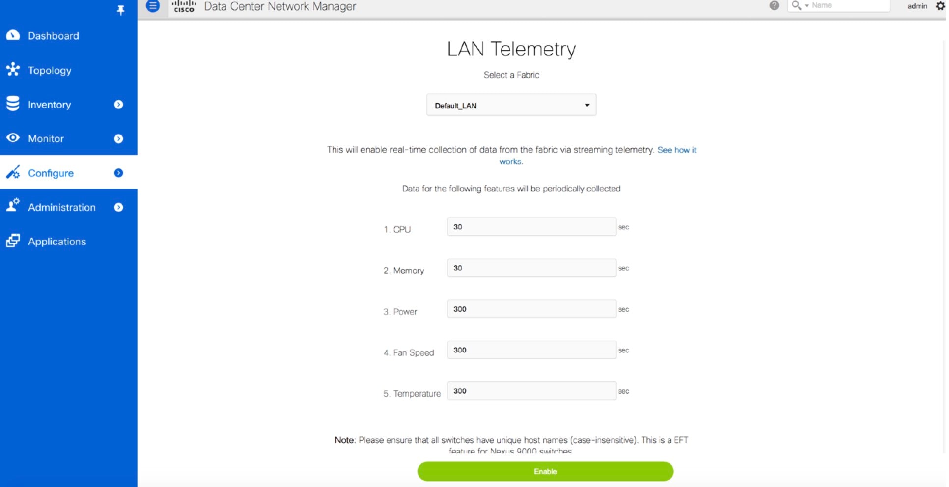
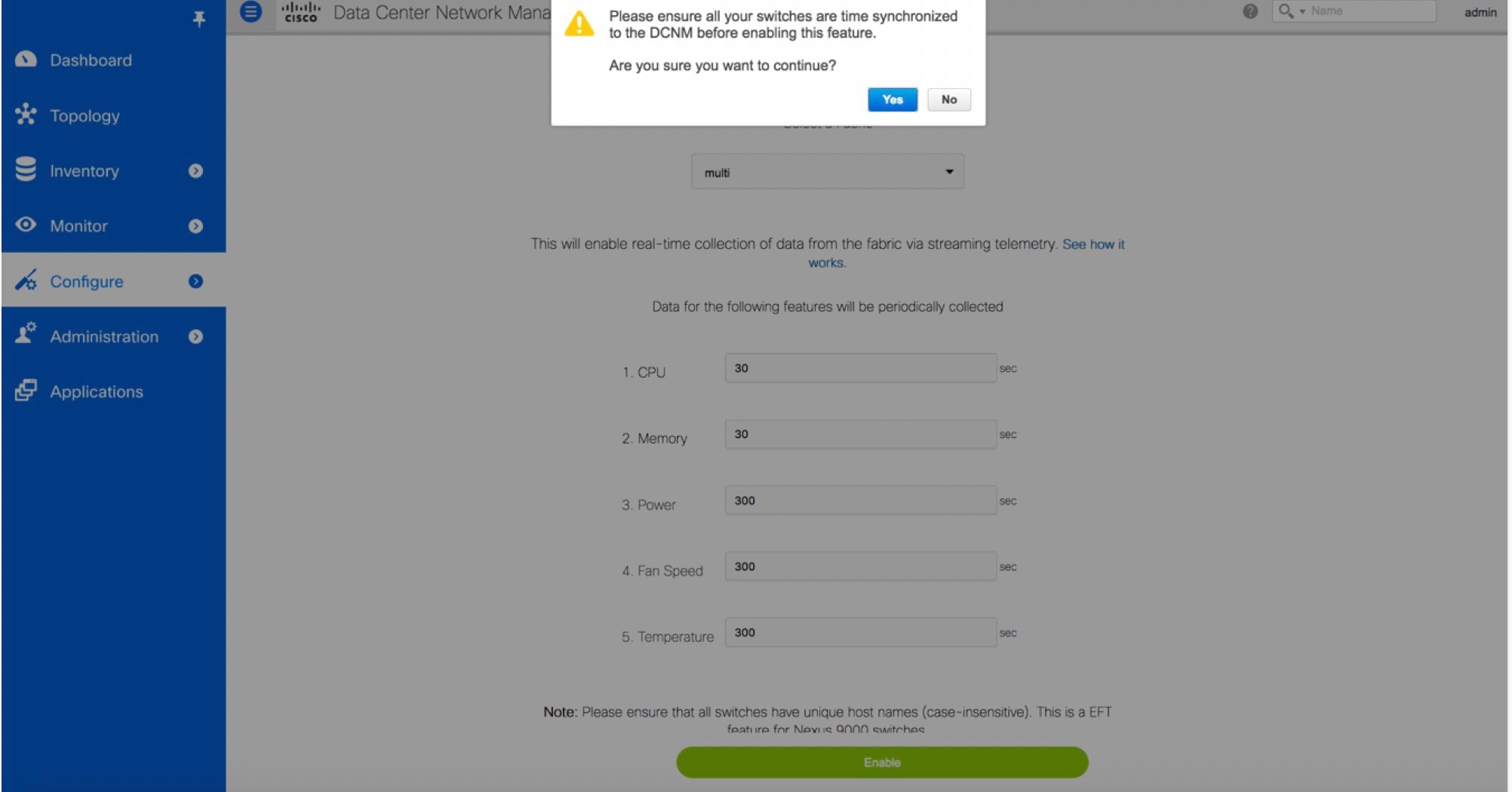
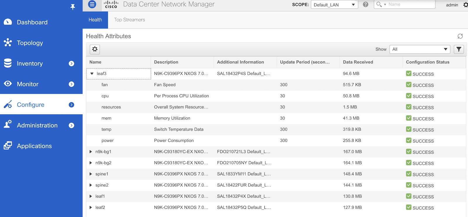
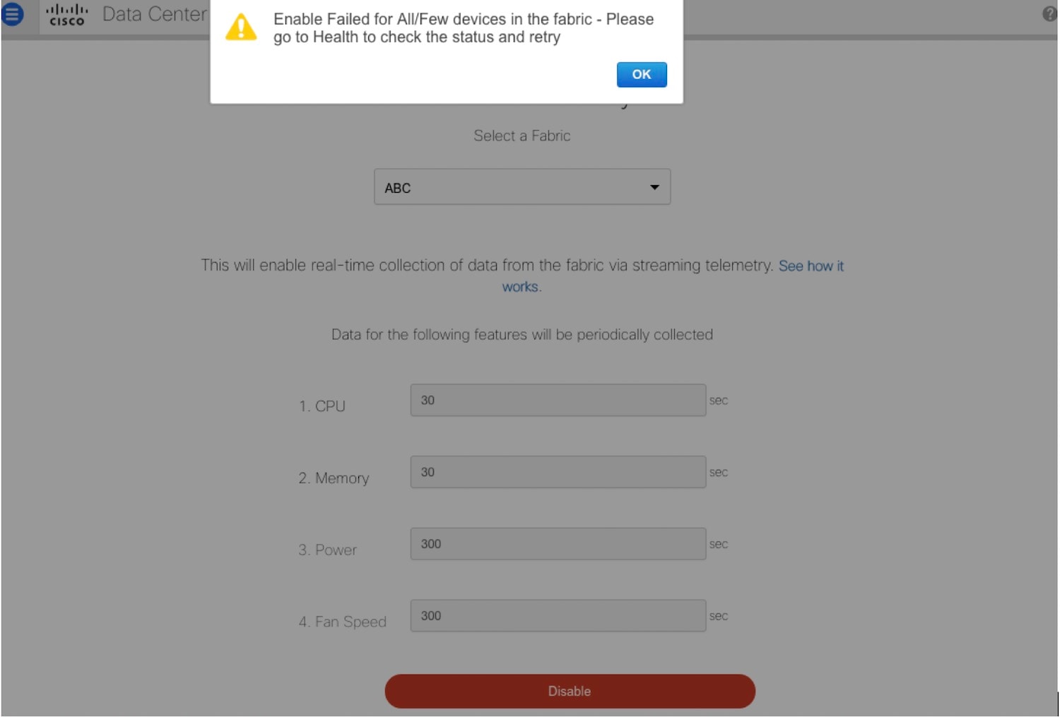
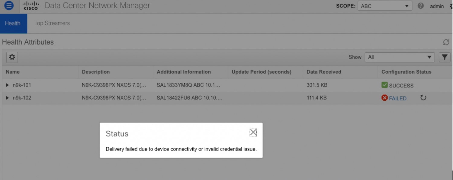
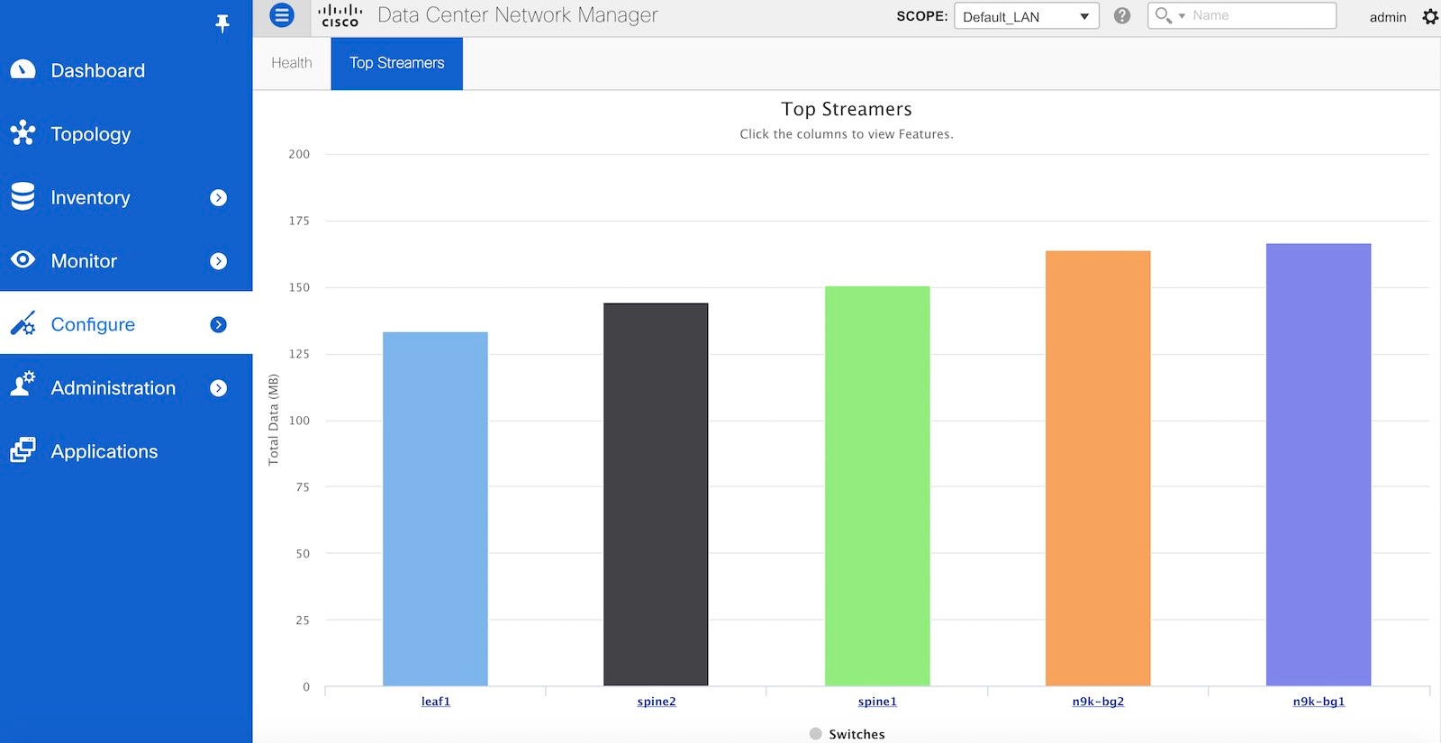
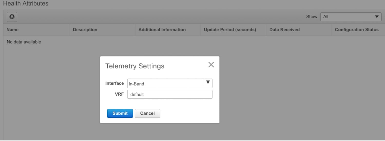
 Feedback