- Preface
- New and Changed Information
- Overview
- Configuring Layer 2 Switching
- Configuring VLANs
- Configuring VTP
- Configuring Private VLANs Using NX-OS
- Configuring Switching Modes
- Configuring Rapid PVST+ Using Cisco NX-OS
- Configuring MST Using Cisco NX-OS
- Configuring STP Extensions Using Cisco NX-OS
- Configuring Reflective Relay for Layer2 Switching
- Index
- Information About VLANs
- Licensing Requirements for VLANs
- Prerequisites for Configuring VLANs
- Guidelines and Limitations for Configuring VLANs
- Default Settings for VLANs
- Configuring a VLAN
- Verifying the VLAN Configuration
- Displaying and Clearing VLAN Statistics
- Configuration Example for VLANs
- Additional References for VLANs
Configuring VLANs
- Information About VLANs
- Licensing Requirements for VLANs
- Prerequisites for Configuring VLANs
- Guidelines and Limitations for Configuring VLANs
- Default Settings for VLANs
- Configuring a VLAN
- Verifying the VLAN Configuration
- Displaying and Clearing VLAN Statistics
- Configuration Example for VLANs
- Additional References for VLANs
Information About VLANs
You can use VLANs to divide the network into separate logical areas at the Layer 2 level. VLANs can also be considered as broadcast domains.
Any switch port can belong to a VLAN, and unicast broadcast and multicast packets are forwarded and flooded only to end stations in that VLAN. Each VLAN is considered a logical network, and packets destined for stations that do not belong to the VLAN must be forwarded through a router.
Understanding VLANs
A VLAN is a group of end stations in a switched network that is logically segmented by function or application, without regard to the physical locations of the users. VLANs have the same attributes as physical LANs, but you can group end stations even if they are not physically located on the same LAN segment.
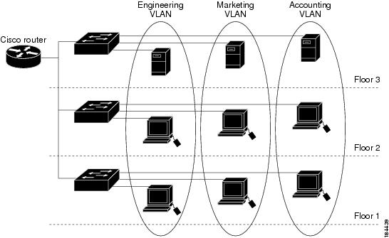
Any switch port can belong to a VLAN, and unicast, broadcast, and multicast packets are forwarded and flooded only to end stations in that VLAN. Each VLAN is considered as a logical network, and packets destined for stations that do not belong to the VLAN must be forwarded through a router. The following figure shows VLANs as logical networks. The stations in the engineering department are assigned to one VLAN, the stations in the marketing department are assigned to another VLAN, and the stations in the accounting department are assigned to another VLAN.
VLANs are usually associated with IP subnetworks. For example, all the end stations in a particular IP subnet belong to the same VLAN. To communicate between VLANs, you must route the traffic.
By default, a newly created VLAN is operational; that is, the newly created VLAN is in the no shutdown condition. Additionally, you can configure VLANs to be in the active state, which is passing traffic, or the suspended state, in which the VLANs are not passing packets. By default, the VLANs are in the active state and pass traffic.
A VLAN interface, or switched virtual interface (SVI), is a Layer 3 interface that is created to provide communication between VLANs. In order to route traffic between VLANs, you must create and configure a VLAN interface for each VLAN. Each VLAN requires only one VLAN interface.
VLAN Ranges
 Note | The extended system ID is always automatically enabled in Cisco Nexus 9000 devices. |
The device supports up to 4095 VLANs in accordance with the IEEE 802.1Q standard. The software organizes these VLANs into ranges, and you use each range slightly differently.
For information about configuration limits, see the verified scalability limits documentation for your switch.
About Reserved VLANS
The following are notes about reserved VLANs (3968 to 4095):
-
The software allocates a group of VLAN numbers for features like multicast and diagnostics, that need to use internal VLANs for their operation. By default, the system allocates a block of 128 reserved VLANs (3968 to 4095) for these internal uses.
-
You can change the range of reserved VLANs with the system vlan vlan-id reserve command. This allows you to set a different range of VLANs to be used as the reserved VLANs. The selected VLANs must be reserved in groups of 128.
-
You may configure VLANs 3968-4092 for other purposes.
-
VLANs 4093-4095 are always reserved for internal use and cannot be used other purposes.
For example, system vlan 400 reserve
reserves VLANs 400-527.The new reserved range takes effect after the running configuration is saved and the device is reloaded.
-
-
The no system vlan vlan-id reserve command changes the range for reserved VLANs to the default range of 3968-4095 after the device is reloaded.
-
Use the show system vlan reserved command to verify the range of the current and future reserved VLAN ranges.
-
Use the show vlan internal usage command to verify the use of different reserved VLANs.
Example of VLAN Reserve
The following is an example of configuring the VLAN reserve (before and after image reload):
**************************************************
CONFIGURE NON-DEFAULT RANGE, "COPY R S" AND RELOAD
**************************************************
switch(config)# system vlan 400 reserve
"vlan configuration 400-527" will be deleted automatically.
Vlans, SVIs and sub-interface encaps for vlans 400-527 need to be removed by the user.
Continue anyway? (y/n) [no] y
Note: After switch reload, VLANs 400-527 will be reserved for internal use.
      This requires copy running-config to startup-config before
      switch reload.  Creating VLANs within this range is not allowed.

switch(config)# show system vlan reserved

system current running vlan reservation: 3968-4095

system future running vlan reservation: 400-527

switch(config)# show vlan internal usage

VLANs                   DESCRIPTION
-------------------     -----------------
3968-4031               Multicast
4032-4035,4048-4059     Online Diagnostic
4036-4039,4060-4087     ERSPAN
4042                    Satellite
3968-4095               Current
4041                    VXLAN Encap

switch(config)# copy running-config startup-config
[########################################] 100%

switch(config)# reload
This command will reboot the system. (y/n)?  [n] y

************
AFTER RELOAD
************

switch# show system vlan reserved

system current running vlan reservation: 400-527

switch# show vlan internal usage

VLANs                   DESCRIPTION
-------------------     -----------------
448-511                 Multicast
400-415                 Online Diagnostic
416-447                 ERSPAN
512                     Satellite
400-527,4093-4094       Current
514                     VXLAN Encap
Creating, Deleting, and Modifying VLANs
Note | By default, all Cisco Nexus 9396 and Cisco Nexus 93128 ports are Layer 2 ports. By default, all Cisco Nexus 9504 and Cisco Nexus 9508 ports are Layer 3 ports. |
VLANs are numbered from 1 to 3967. All ports that you have configured as switch ports belong to the default VLAN when you first bring up the switch as a Layer 2 device. The default VLAN (VLAN1) uses only default values, and you cannot create, delete, or suspend activity in the default VLAN.
You create a VLAN by assigning a number to it; you can delete VLANs and move them from the active operational state to the suspended operational state. If you attempt to create a VLAN with an existing VLAN ID, the device goes into the VLAN submode but does not create the same VLAN again.
Newly created VLANs remain unused until Layer 2 ports are assigned to the specific VLAN. All the ports are assigned to VLAN1 by default.
Depending on the range of the VLAN, you can configure the following parameters for VLANs (except the default VLAN):
You can configure VLAN long-names of up to 128 characters. To configure VLAN long-names, VTP must be in transparent mode.
Note | See the Cisco Nexus 9000 Series NX-OS Interfaces Configuration Guide for information on configuring ports as VLAN access or trunk ports and assigning ports to VLANs. |
When you delete a specified VLAN, the ports associated to that VLAN become inactive and no traffic flows. When you delete a specified VLAN from a trunk port, only that VLAN is shut down and traffic continues to flow on all the other VLANs through the trunk port.
However, the system retains all the VLAN-to-port mapping for that VLAN, and when you reenable or re-create, that specified VLAN, the system automatically reinstates all the original ports to that VLAN. The static MAC addresses and aging time for that VLAN are not restored when the VLAN is reenabled.
Note | Commands entered in the VLAN configuration submode are not immediately executed. You must exit the VLAN configuration submode for configuration changes to take effect. |
High Availability for VLANs
The software supports high availability for both stateful and stateless restarts, as during a cold reboot, for VLANs. For the stateful restarts, the software supports a maximum of three retries. If you try more than 3 times within 10 seconds of a restart, the software reloads the supervisor module.
You can upgrade or downgrade the software seamlessly when you use VLANs.
Note | See the Cisco Nexus 9000 Series NX-OS High Availability and Redundancy Guide, for complete information on high availability features. |
Licensing Requirements for VLANs
The following table shows the licensing requirements for this feature.
|
Product |
License Requirement |
|---|---|
|
Cisco NX-OS |
VLANs require no license. Any feature not included in a license package is bundled with the Cisco NX-OS system images and is provided at no extra charge to you. |
Prerequisites for Configuring VLANs
VLANs have the following prerequisites:
Guidelines and Limitations for Configuring VLANs
VLANs have the following configuration guidelines and limitations:
-
You can configure a single VLAN or a range of VLANs.
When you configure a large number of VLANs, first create the VLANs using the vlan command (for example, vlan 200-300, 303-500). After the VLANS have been successfully created, name or configure those VLANs sequentially.
-
You cannot create, modify, or delete any VLANs that are within the group of VLANs reserved for internal use.
-
VLAN1 is the default VLAN. You cannot create, modify, or delete this VLAN.
-
VLANs 1006 to 3967 are always in the active state and are always enabled. You cannot suspend the state or shut down these VLANs.
-
When the spanning tree mode is changed, the Layer 3 subinterface VLANs that share the same VLAN IDs with Layer 2 VLANs might be affected by a few micro-seconds of traffic drops as a result of the hardware re-programming.
-
VLANs 3968 to 4095 are reserved for internal device use by default.
Default Settings for VLANs
Configuring a VLAN
Note | See the Cisco Nexus 9000 Series NX-OS Interfaces Configuration Guide, for information on assigning Layer 2 interfaces to VLANs (access or trunk ports). All interfaces are in VLAN1 by default. |
Note | If you are familiar with the Cisco IOS CLI, be aware that the Cisco NX-OS commands for this feature might differ from the Cisco IOS commands that you would use. |
- Creating and Deleting a VLAN - CLI Version
- Entering the VLAN Configuration Submode
- Configuring a VLAN
- Configuring a VLAN Before Creating the VLAN
- Enabling the VLAN Long-Name
Creating and Deleting a VLAN - CLI Version
You can create or delete all VLANs except the default VLAN and those VLANs that are internally allocated for use by the device.
Once a VLAN is created, it is automatically in the active state.
Note | When you delete a VLAN, ports associated to that VLAN become inactive. Therefore, no traffic flows and the packets are dropped. On trunk ports, the port remains open and the traffic from all other VLANs except the deleted VLAN continues to flow. |
If you create a range of VLANs and some of these VLANs cannot be created, the software returns a message listing the failed VLANs, and all the other VLANs in the specified range are created.
Note | You can also create and delete VLANs in the VLAN configuration submode. |
1.
config t
2.
vlan {vlan-id | vlan-range}
3.
exit
4.
(Optional)
show vlan
5.
(Optional)
copy running-config startup-config
DETAILED STEPS
This example shows how to create a range of VLANs from 15 to 20:
switch# config t switch(config)# vlan 15-20 switch(config-vlan)# exit switch(config)#
Entering the VLAN Configuration Submode
To configure or modify the VLAN for the following parameters, you must be in the VLAN configuration submode:
1.
config t
2.
vlan {vlan-id | vlan-range}
3.
exit
4.
(Optional)
show vlan
5.
(Optional)
copy running-config startup-config
DETAILED STEPS
This example shows how to enter and exit the VLAN configuration submode:
switch# config t switch(config)# vlan 15 switch(config-vlan)# exit switch(config)#
Configuring a VLAN
To configure or modify a VLAN for the following parameters, you must be in the VLAN configuration submode:
Note | You cannot create, delete, or modify the default VLAN or the internally allocated VLANs. Additionally, some of these parameters cannot be modified on some VLANs. |
1.
config
t
2.
vlan
{vlan-id |
vlan-range}
3.
name
vlan-name
4.
state
{active
|
suspend}
5.
no
shutdown
6.
exit
7.
(Optional)
show
vlan
8.
(Optional) show vtp status
9.
(Optional)
copy
running-config startup-config
DETAILED STEPS
This example shows how to configure optional parameters for VLAN 5:
switch# config t switch(config)# vlan 5 switch(config-vlan)# name accounting switch(config-vlan)# state active switch(config-vlan)# no shutdown switch(config-vlan)# exit switch(config)#
Configuring a VLAN Before Creating the VLAN
Note | The show vlan command does not display these VLANs unless you create it using the vlan command. |
1.
config t
2.
vlan configuration {vlan-id}
DETAILED STEPS
| Command or Action | Purpose |
|---|
switch# config t switch(config)# vlan configuration 20 switch(config-vlan-config)#
Enabling the VLAN Long-Name
You can configure VLAN long-names of up to 128 characters.
Note | When system vlan long-name is included in the start-up configuration, the Cisco Nexus 9000 Series switch boots up in VTP off mode. To enable VTP transparent mode: |
VTP must be in transparent or in off mode. VTP cannot be in client or server mode. For more details about VTP, see Configuring VTP.
1.
configure terminal
2.
system vlan long-name
3.
(Optional) copy running-config startup-config
4.
show running-config vlan
DETAILED STEPS
| Command or Action | Purpose | |
|---|---|---|
| Step 1 | configure terminal Example: switch# configure terminal switch(config)# |
Enters global configuration mode. |
| Step 2 | system vlan long-name
Example: switch(config)# system vlan long-name |
Allows you to enable VLAN names that have up to 128 characters. Use the no form of this command to disable this feature. |
| Step 3 | copy running-config startup-config Example: switch(config)# copy running-config startup-config | (Optional) Saves the change persistently through reboots and restarts by copying the running configuration to the startup configuration. |
| Step 4 | show running-config vlan
Example: switch(config)# show running-config vlan | Verifies that the system VLAN long-name feature is enabled. |
switch# configure terminal switch(config)# system vlan long-name switch(config)# copy running config startup config switch(config)# show running-config vlan
Verifying the VLAN Configuration
|
Command |
Purpose |
|---|---|
| show running-config vlan vlan-id |
Displays VLAN information. |
| show vlan [all-ports | brief | id vlan-id | name name | dot1q tag native] |
Displays VLAN information. |
|
show vlan summary |
Displays a summary of VLAN information. |
|
show vtp status |
Displays VTP information. |
Displaying and Clearing VLAN Statistics
|
Command |
Purpose |
|---|---|
|
clear vlan [id vlan-id] counters |
Clears counters for all VLANs or for a specified VLAN. |
|
show vlan counters |
Displays information on Layer 2 packets in each VLAN. |
Configuration Example for VLANs
The following example shows how to create and name a VLAN as well as how to make the state active and administratively up:
switch# configure terminal
switch(config)# vlan 10
switch(config-vlan)# name test
switch(config-vlan)# state active
switch(config-vlan)# no shutdown
switch(config-vlan)# exit
switch(config)#
Additional References for VLANs
Related Documents
|
Related Topic |
Document Title |
|---|---|
|
NX-OS Layer 2 switching configuration |
Cisco Nexus 9000 Series NX-OS Layer 2 Switching Configuration Guide |
|
Interfaces, VLAN interfaces, IP addressing, and port channels |
Cisco Nexus 9000 Series NX-OS Interfaces Configuration Guide |
|
Multicast routing |
Cisco Nexus 9000 Series NX-OS Multicast Routing Configuration Guide |
|
NX-OS fundamentals |
Cisco Nexus 9000 Series NX-OS Fundamentals Configuration Guide |
|
High availability |
Cisco Nexus 9000 Series NX-OS High Availability and Redundancy Guide |
|
System management |
Cisco Nexus 9000 Series NX-OS System Management Configuration Guide |
Standards
|
Standards |
Title |
|---|---|
|
No new or modified standards are supported by this feature, and support for existing standards has not been modified by this feature. |
— |
MIBs
|
MIBs |
MIBs Link |
|---|---|
|
|
To locate and download MIBs, go to the following URL: ftp://ftp.cisco.com/pub/mibs/supportlists/nexus9000/Nexus9000MIBSupportList.html |
 Feedback