-
null
Installing the Switch Chassis
- Safety
- Installation Options with Racks and Cabinets
- Airflow Considerations
- Installation Guidelines
- Unpacking and Installing the Switch
- Installing the Switch
- Grounding the Chassis
- Starting the Switch
Safety
Before you install, operate, or service the switch, see the Regulatory, Compliance, and Safety Information for the Cisco Nexus 3000 and 9000 Series for important Safety Information.
 Warning | Statement 1071—Warning Definition IMPORTANT SAFETY INSTRUCTIONS This warning symbol means danger. You are in a situation that could cause bodily injury. Before you work on any equipment, be aware of the hazards involved with electrical circuitry and be familiar with standard practices for preventing accidents. Use the statement number provided at the end of each warning to locate its translation in the translated safety warnings that accompanied this device. SAVE THESE INSTRUCTIONS |
 Note | Statement 1017—Restricted Area This unit is intended for installation in restricted access areas. A restricted access area can be accessed only through the use of a special tool, lock and key, or other means of security. |
Note | Statement 1030—Equipment Installation Only trained and qualified personnel should be allowed to install, replace, or service this equipment. |
Installation Options with Racks and Cabinets
You can install the switch in the following types of racks using the rack-mount kit shipped with the switch:
The rack or cabinet that you use must meet the requirements listed in General Requirements for Cabinets and Racks
The rack-mount kit enables you to install the switch into racks of varying depths. You can use the rack-mount kit parts to position the switch with easy access to either the port connections end of the chassis or the end of the chassis with the fan and power supply modules. For instructions on how to install the rack-mount kit, see the Installing the Switch.
Airflow Considerations
The switch comes with fan and power supply modules that have either port-side intake or port-side exhaust airflow for cooling the switch. If you are positioning the port end of the switch in a cold aisle, make sure that the switch has port-side intake modules with burgundy colorings on the fan and AC power supplies and green markings on DC power supplies. If you are positioning the fan and power supply modules in a cold aisle, make sure that the switch has port-side exhaust modules with blue colorings.
Installation Guidelines
When installing the switch, follow these guidelines:
-
Record equipment and installation information in the forms presented in Appendix E, "Site Planning and Maintenance Records" as you install and configure the switch.
-
Ensure that there is adequate space around the switch to allow for servicing the switch and for adequate airflow (see Clearance Requirements).
-
Ensure that you are positioning the switch in a rack so that it takes in cold air from the cold aisle and exhausts air to the hot aisle. If there is blue coloring on the fan tray and AC power supply modules, the switch is configured for port-side exhaust and you must position the fan and power supply modules in a cold aisle. If there is burgundy coloring on the fan and AC power supply modules or green coloring on the DC power supply modules, the switch is configured for port-side intake and you must position the ports in a cold aisle.
-
Ensure that the chassis can be adequately grounded. If the switch is not mounted in a grounded rack, we recommend connecting both the system ground on the chassis directly to an earth ground.
-
Ensure that the site power meets the power requirements listed in Appendix B System Specifications. If available, you can use an uninterruptible power supply (UPS) to protect against power failures.

Caution
Avoid UPS types that use ferroresonant technology. These UPS types can become unstable with the switch, which can have substantial current draw fluctuations because of fluctuating data traffic patterns.
-
Ensure that circuits are sized according to local and national codes. Typically, this often requires one or both of the following:
-
AC power supplies typically require at least a 15-A or 20-A AC circuit.
-
DC power supplies require the following:
Caution
To prevent loss of input power, ensure the total maximum loads on the circuits supplying power to the switch are within the current ratings for the wiring and breakers.
-
Unpacking and Installing the Switch
Before you install the switch, be sure to unpack and inspect the switch for damage or missing components. If anything is missing or damaged, contact your customer service representative immediately.
 Tip | Keep the shipping container in case the chassis requires shipping at a later time. |
Before you unpack the switch and before you handle any switch components, be sure that you are wearing a grounded electrostatic discharge (ESD) strap. To ground the strap, attach it directly to an earth ground or to a grounded rack or grounded chassis (there must be a metal-to-metal connection to the earth ground).
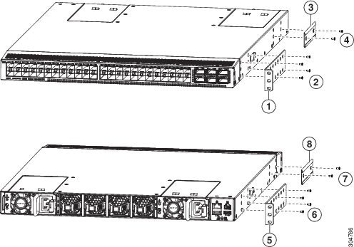
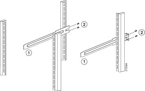
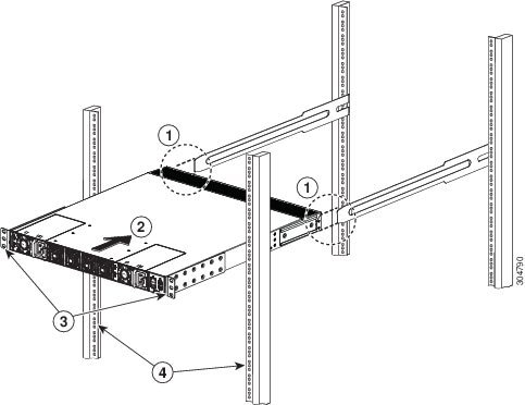
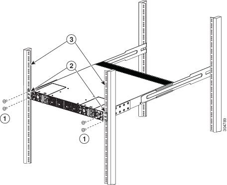
Installing the Switch
To install the switch, you must attach front and rear mounting brackets to the switch, install slider rails on the rear of the rack, slide the switch onto the slider rails, and secure the switch to the front of the rack. Typically, the front of the rack is the side easiest to access for maintenance.
Note | You must supply the eight 10-32 or 12-24 screws required to mount the slider rails and switch to the rack. |
Grounding the Chassis
The switch is grounded when you connect the chassis and the power supplies to the earth ground in the following ways:
-
You connect the chassis (at its grounding pad) to the data center ground. If the rack is fully-bonded and grounded, you can ground the switch by connecting it to the rack.
Note
The chassis ground connection is active even when the power supply modules have not been grounded or connected to the switch.
-
You connect each AC power supply to the earth ground automatically when you connect the power supply to an AC power source (see Powering Up the Switch).
-
You connect each DC power supply to the earth ground when you connect the power cables to the connector block and insert the connector block to the power supply (see Powering Up the Switch).
Warning | Statement 1024—Ground Conductor This equipment must be grounded. Never defeat the ground conductor or operate the equipment in the absence of a suitably installed ground conductor. Contact the appropriate electrical inspection authority or an electrician if you are uncertain that suitable grounding is available. |
Warning | Statement 1046—Installing or Replacing the Unit When installing or replacing the unit, the ground connection must always be made first and disconnected last. |
Before you can ground the chassis, you must have a connection to the earth ground for the data center building. If you installed the switch chassis into a bonded rack (see the rack manufacturer's instructions for more information) that now has a connection to the data center earth ground, you can ground the chassis by connecting its grounding pad to the rack. Otherwise, you must connect the chassis grounding pad directly to the data center ground.
| Step 1 | Use a wire-stripping tool to remove approximately 0.75 inch (19 mm) of the covering from the end of the grounding wire. | ||||||||
| Step 2 | Insert the
stripped end of the grounding wire into the open end of the grounding lug, and
use a crimping tool to crimp the lug to the wire (see Callout 2 in the
following figure). Verify that the ground wire is securely attached to the
grounding lug by attempting to pull the wire out of the crimped lug.
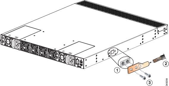
| ||||||||
| Step 3 | Secure the grounding lug to the chassis grounding pad with two M4 screws (see Callouts 1 and 3 in the previous figure), and tighten the screws to 11 to 15 in-lb (1.24 to 1.69 N·m) of torque. | ||||||||
| Step 4 | Prepare the other end of the grounding wire and connect it to an appropriate grounding point in your site to ensure an adequate earth ground for the switch. If the rack is fully bonded and grounded, connect the grounding wire as explained in the documentation provided by the vendor for the rack. |
Starting the Switch
You start the switch by connecting it to its dedicated power source. If you need power-supply redundancy, you must connect each of the power supplies to one or two power sources. If you need grid redundancy, you must connect each power supply in a switch to a different power source.
-
The switch must be installed and secured to a rack or cabinet.
-
The rack must be close enough to the dedicated power source so that you can connect the switch to the power source by using a designated power cables.
-
You have a designated power cable for each power supply that you are connecting to the dedicated power source.
Note
Depending on the outlet receptacle on your AC power distribution unit, you might need an optional jumper power cord to connect the switch to your outlet receptacle.
-
The switch is not connected to the network (this includes any management or interface connections).
-
The fan and power supply modules are fully secured in their chassis slots.
All of the fan slots must be filled with fan modules. The power supply slots must have at least one power supply. If there is an open power supply slot, it must have a blank filler plate installed to preserve the designed airflow.
-
Ensure that the switch is adequately grounded (see Grounding the Chassis).
| Step 1 | Connect each
power supply to a power source as follows:
| ||
| Step 2 | Listen for the fans; they should begin operating when the power supply is powered. | ||
| Step 3 | After the
switch boots, verify that the LEDs are lit as follows:
| ||
| Step 4 | Verify that the system software has booted and the switch has initialized without error messages. | ||
| Step 5 | Complete the
worksheets provided in
Appendix
E, "Site Planning and Maintenance Records," for future reference.
A setup utility automatically launches the first time that you access the switch and guides you through the basic configuration. For instructions on how to configure the switch and check module connectivity, see the appropriate Cisco Nexus 93xxx configuration guide. |
 Feedback