Overview
This chapter provides an architectural overview of the Cisco Nexus 2000 Series Fabric Extender and includes the following sections:
- Information About the Cisco Nexus 2000 Series Fabric Extender
- Fabric Extender Terminology
- Fabric Extender Features
- Oversubscription
- Management Model
- Forwarding Model
- Connection Model
- Port Numbering Convention
- Fabric Extender Image Management
- Fabric Extender Hardware
- Host Interfaces
- Host EtherChannel
- VLANs and Private VLANs
- Virtual Port Channels
- Fibre Channel over Ethernet Support
- Protocol Offload
- Quality of Service
- Access Control Lists
- IGMP Snooping
- Switched Port Analyzer
- Fabric Interface Features
- Static Pinning Fabric Interface Connection
- EtherChannel Fabric Interface Connection
- Chassis
- Ethernet Interfaces
Information About the Cisco Nexus 2000 Series Fabric Extender
The Cisco Nexus 2000 Series Fabric Extender is a highly scalable and flexible server networking solution that works with Cisco Nexus 5000 Series devices to provide high-density, low-cost connectivity for server aggregation. Scaling across 1-Gigabit Ethernet, 10-Gigabit Ethernet, unified fabric, rack, and blade server environments, the Fabric Extender is designed to simplify data center architecture and operations.
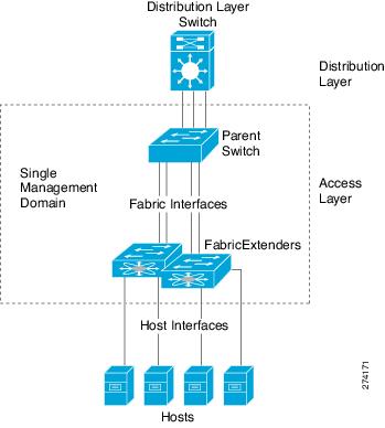
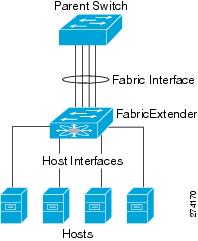
The Fabric Extender integrates with its parent switch, the Cisco Nexus 5000 Series device, to allow automatic provisioning and configuration taken from the settings on the parent switch. This integration allows large numbers of servers and hosts to be supported using the same feature set as the parent switch, including security and quality of service (QoS) configuration parameters, with a single management domain as shown in the following figure. The Fabric Extender and its parent switch enable a large multi-path, loop-free, active-active data center topology without the use of Spanning Tree Protocol (STP).
The Cisco Nexus 2000 Series Fabric Extender forwards all traffic to its parent Cisco Nexus 5000 Series device over 10-Gigabit Ethernet fabric uplinks, allowing all traffic to be inspected by policies established on the Cisco Nexus 5000 Series device.
No software is included with the Fabric Extender. Software is automatically downloaded and upgraded from its parent switch.
Fabric Extender Terminology
Some terms used in this document are as follows:
-
Fabric interface—A 10-Gigabit Ethernet uplink port designated for connection from the Fabric Extender to its parent switch. A fabric interface cannot be used for any other purpose. It must be directly connected to the parent switch.

Note
A fabric interface includes the corresponding interface on the parent switch. This interface is enabled when you enter the switchport mode fex-fabric command.
-
EtherChannel fabric interface—An EtherChannel uplink connection from the Fabric Extender to its parent switch. This connection consists of fabric interfaces bundled into a single logical channel.
-
Host interface—An Ethernet host interface for connection to a server or host system.
Note
Do not connect a bridge or switch to a host interface. These interfaces are designed to provide end host or server connectivity.
-
EtherChannel host interface—An EtherChannel host interface for connection to a server or host system.
Fabric Extender Features
The Cisco Nexus 2000 Series Fabric Extender allows a single switch—and a single consistent set of switch features—to be supported across a large number of hosts and servers. By supporting a large server-domain under a single management entity, policies can be enforced more efficiently.
Some of the features of the parent switch cannot be extended onto the Fabric Extender.
- Host Interfaces
- Host EtherChannel
- VLANs and Private VLANs
- Virtual Port Channels
- Fibre Channel over Ethernet Support
- Protocol Offload
- Quality of Service
- Access Control Lists
- IGMP Snooping
- Switched Port Analyzer
- Fabric Interface Features
Host Interfaces
Host interfaces are for host or server connectivity only; host interfaces cannot connect to another network. These interfaces are always enabled as edge ports; as they come up, these ports immediately transition to the forwarding state. Host interfaces are always enabled with BPDU Guard. If a BPDU is received, the port is immediately placed in an error-disabled state which keeps the link down.
You can enable host interfaces to accept Cisco Discovery Protocol (CDP) packets. This protocol only works when it is enabled for both ends of a link.
Note |
CDP is not supported on fabric interfaces when the Fabric Extender is configured in a virtual port channel (vPC) topology. |
Ingress and egress packet counters are provided on each host interface.
For more information about BPDU Guard and CDP see the Cisco Nexus 5000 Series NX-OS Layer 2 Switching Configuration Guide, Release 4.2(1)N1(1).
Host EtherChannel
The Cisco Nexus 2248TP and Cisco Nexus 2232PP support EtherChannel host interface configurations. Up to 8 interfaces can be combined in an EtherChannel. The EtherChannel can be configured with or without LACP.
Note |
Support for host interface EtherChannel was added to the Fabric Extender from Cisco NX-OS Release 4.2(1)N1(1). |
For more information about EtherChannels see the Cisco Nexus 5000 Series NX-OS Layer 2 Switching Configuration Guide, Release 4.2(1)N1(1).
VLANs and Private VLANs
The Fabric Extender supports Layer 2 VLAN trunks and IEEE 802.1Q VLAN encapsulation. Host interfaces can be members of private VLANs with the following restrictions:
-
You can configure a host interface as an isolated or community access port only.
-
You cannot configure a host interface as a promiscuous port.
-
You cannot configure a host interface as a private VLAN trunk port.
For more information about promiscuous, community, and isolated ports in private VLANs see the Cisco Nexus 5000 Series NX-OS Layer 2 Switching Configuration Guide, Release 4.2(1)N1(1).
Virtual Port Channels
Using a virtual port channel (vPC) you can configure topologies where a Cisco Nexus 2000 Series Fabric Extender is connected to a pair of parent switches or a pair of Fabric Extenders are connected to a single parent switch. The vPC can provide multipath connections, which allow you to create redundancy between the nodes on your network.
The following vPC topologies are possible with the Fabric Extender:
-
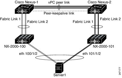
The parent switches are connected single homed to Fabric Extenders which are subsequently connected to servers with dual interfaces (see the following figure).
Figure 2. Single Homed Fabric Extender vPC Topology
-
The Fabric Extender is connected dual homed to two upstream parent switches and connected downstream to single homed servers (see the following figure).
Figure 3. Dual Homed Fabric Extender vPC Topology
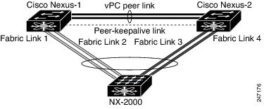
This configuration is also called Active-Active topology.
See the Cisco Nexus 5000 Series NX-OS Layer 2 Switching Configuration Guide, Release 4.2(1)N1(1) for vPC configuration details.
Fibre Channel over Ethernet Support
The Cisco Nexus 2232PP supports Fibre Channel over Ethernet (FCoE) with the following restrictions:
-
Only FCoE Initialization Protocol (FIP) enabled converged network adapters (CNAs) are supported on the Fabric Extender.
-
Binding to an EtherChannel is limited to only one member EtherChannel.
See the Cisco Nexus 5000 Series NX-OS Fibre Channel over Ethernet Configuration Guide, Release 4.2(1)N1(1) for configuration details.
Protocol Offload
To reduce the load on the control plane of the Cisco Nexus 5000 Series device, Cisco NX-OS provides the ability to offload link-level protocol processing to the Fabric Extender CPU. The following protocols are supported:
Quality of Service
The Fabric Extender provides two user queues for its quality of service (QoS) support, one for all no-drop classes and one for all drop classes. The classes configured on its parent switch are mapped to one of these two queues; traffic for no-drop classes is mapped to one queue and traffic for all drop classes is mapped to the other. Egress policies are also restricted to these two classes.
The parent switch provides two predefined type qos class maps for matching broadcast or multicast traffic; class-all-flood and class-ip-multicast. These classes are ignored on the Fabric Extender.
The Fabric Extender uses IEEE 802.1p class of service (CoS) values to associate traffic with the appropriate class. Per-port QoS configuration and CoS-based egress queuing is also supported.
Host interfaces support pause frames, which is implemented using IEEE 802.3x link-level flow control (LLC). By default, flow control send is on and flow control receive is off on all host interfaces. Autonegotiation is enabled on the host interfaces. Per-class flow control is set according to the QoS classes.
Host interfaces support jumbo frames (up to 9216 bytes); however a per-host interface maximum transmission unit (MTU) is not supported. Instead, MTU is set according to the QoS classes. You modify MTU by setting policy and class maps on the parent switch. Because the Fabric Extender has only two user queues, the MTU for the drop-queue is set to the maximum MTU of all drop classes and the MTU on the no-drop queue is set to the maximum MTU of all no-drop classes.
For more information about LLC and quality of service, see the Cisco Nexus 5000 Series NX-OS Quality of Service Configuration Guide, Release 4.2(1)N1(1).
Access Control Lists
The Fabric Extender supports the full range of ingress access control lists (ACLs) that are available on its parent switch.
For more information about ACLs see the Cisco Nexus 5000 Series NX-OS Security Configuration Guide, Release 4.2(1)N1(1).
IGMP Snooping
IGMP snooping is supported on all host interfaces of the Fabric Extender.
The Fabric Extender and its parent switch support IGMPv3 snooping based only on the destination multicast MAC address. It does not support snooping based on the source MAC address or on proxy reports.
Note |
For more information about IGMP snooping, see http://tools.ietf.org/wg/magma/draft-ietf-magma-snoop/rfc4541.txt. Also see the Cisco Nexus 5000 Series NX-OS Layer 2 Switching Configuration Guide, Release 4.2(1)N1(1). |
Switched Port Analyzer
You can configure the host interfaces on the Fabric Extender as Switched Port Analyzer (SPAN) source ports. Fabric Extender ports cannot be configured as a SPAN destination. Only one SPAN session is supported for all the host interfaces on the same Fabric Extender. Ingress source (Rx), egress source (Tx), or both ingress and egress monitoring is supported.
Note |
All IP multicast traffic on the set of VLANs that a Fabric Extender host interface belongs to is captured in the SPAN session. It is not possible to separate the traffic by IP multicast group membership. If ingress and egress monitoring is configured for host interfaces on the same Fabric Extender, you may see a packet twice: once as the packet ingresses on an interface with Rx configured, and again as the packet egresses on an interface with Tx configured. |
For more information about SPAN see the Cisco Nexus 5000 Series NX-OS System Management Configuration Guide, Release 4.2(1)N1(1)
Fabric Interface Features
The Fabric Extender fabric interfaces support static EtherChannel and priority flow control (PFC). PFC allows you to apply pause functionality to specific classes of traffic on an interface (instead of all the traffic on the interface). During the initial discovery and association process, SFP+ validation and digital optical monitoring (DOM) are performed as follows:
-
The Fabric Extender performs a local check on the uplink SFP+ transceiver. If it fails the security check, the LED flashes but the link is still allowed to come up.
-
The Fabric Extender local check is bypassed if it is running its backup image.
-
The parent switch performs SFP validation again when the fabric interface is brought up. It keeps the fabric interface down if SFP validation fails.
Once an interface on the parent switch is configured in fex-fabric mode, all other features that were configured on that port and are not relevant to this mode are deactivated. If the interface is reconfigured to remove fex-fabric mode, the previous configurations are reactivated.
Note |
Per class flow control mode is enabled by default on the fabric interfaces. When a fabric interface is configured on the parent switch, PFC mode is enabled by default and cannot be changed. |
For more information about PFC see the Cisco Nexus 5000 Series NX-OS Quality of Service Configuration Guide, Release 4.2(1)N1(1)
Oversubscription
In a switching environment, oversubscription is the practice of connecting multiple devices to the same interface to optimize port usage. An interface can support a connection that runs at its maximum speed but because most interfaces do not run at their maximum speeds, you can take advantage of unused bandwidth by sharing ports. In the case of the Cisco Nexus 2000 Series Fabric Extender, oversubscription, which is a function of the available fabric interfaces to active host interfaces, provides cost-effective scalability and flexiblity for Ethernet environments.
The Cisco Nexus 2148T Fabric Extender has four 10-Gigabit Ethernet fabric interfaces and 48 1000BASE-T (1-Gigabit) Ethernet host interfaces. With this system, you can have any number of configurations. For example, you can configure the following:
-
No oversubscription (40 host interfaces for four fabric interfaces)
-
1.2 to 1 oversubscription (48 host interfaces for four fabric interfaces)
-
4.8 to 1 oversubscription (48 host interfaces for one fabric interface)
The Cisco Nexus 2248TP Fabric Extender has four 10-Gigabit Ethernet fabric interfaces and 48 100/1000BASE-T (100-Megabit/1-Gigabit) Ethernet host interfaces. It offers similar configurations to the Cisco Nexus 2148T when its host interfaces are running in Gigabit Ethernet mode. It can easily be run with no oversubscription when its host interfaces are running in 100-Megabit mode.
The Cisco Nexus 2232PP Fabric Extender has eight 10-Gigabit Ethernet fabric interfaces and 32 10-Gigabit Ethernet host interfaces. With this system, you can have a 4 to 1 oversubscription (4 host interfaces for one fabric interface) or higher.
Management Model
The Cisco Nexus 2000 Series Fabric Extender is managed by its parent switch over the fabric interfaces through a zero-touch configuration model. The Fabric Extender is discovered by the switch by detecting the fabric interfaces of the Fabric Extender.
After discovery, if the Fabric Extender has been correctly associated with the parent switch, the following operations are performed:
-
The switch checks the software image compatibility and upgrades the Fabric Extender if necessary.
-
The switch and Fabric Extender establish in-band IP connectivity with each other. The switch assigns an IP address in the range of loopback addresses (127.15.1.0/24) to the Fabric Extender to avoid conflicts with IP addresses that may be in use on the network.
-
The switch pushes the configuration data to the Fabric Extender. The Fabric Extender does not store any configuration locally.
-
The Fabric Extender updates the switch with its operational status. All Fabric Extender information is displayed using the switch commands for monitoring and troubleshooting.
Note |
Prior to Cisco NX-OS Release 4.1(3)N1(1), a Cisco Nexus 2000 Series Fabric Extender could be managed by one parent switch only. |
Forwarding Model
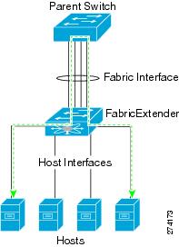
The Cisco Nexus 2000 Series Fabric Extender does not perform any local switching. All traffic is sent to the parent switch that provides central forwarding and policy enforcement, including host-to-host communications between two systems connected to the same Fabric Extender as shown in the following figure.
The forwarding model facilitates feature consistency between the Fabric Extender and its parent switch.
Note |
The Fabric Extender provides end-host connectivity into the network fabric. As a result, Bridge Protocol Data Unit (BPDU) Guard is enabled on all its host interfaces. If you connect a bridge or switch to a host interface, that interface is placed in an error-disabled state when a BPDU is received. You cannot disable BPDU Guard on the host interfaces of the Fabric Extender. |
The Fabric Extender supports egress multicast replication from the network to the host. Packets sent from the parent switch for multicast addresses attached to the Fabric Extender are replicated by the Fabric Extender ASICs and then sent to corresponding hosts.
Connection Model
Two methods (the static pinning fabric interface connection and the EtherChannel fabric interface connection) allow the traffic from an end host to the parent switch to be distributed when going through the Cisco Nexus 2000 Series Fabric Extender.
Static Pinning Fabric Interface Connection
To provide a deterministic relationship between the host interfaces and the parent switch, you can configure the Fabric Extender to use individual fabric interface connections. This configuration connects the 10-Gigabit Ethernet fabric interfaces as shown in the following figure. You can use any number of fabric interfaces up to the maximum available on the model of the Fabric Extender.
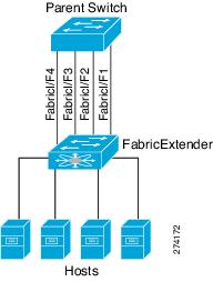
When the Fabric Extender is brought up, its host interfaces are distributed equally among the available fabric interfaces. As a result, the bandwidth that is dedicated to each end host toward the parent switch is never changed by the switch but instead is always specified by you.
Note |
If a fabric interface fails, all its associated host interfaces are brought down and remain down until the fabric interface is restored. |
You must use the pinning max-links command to create a number of pinned fabric interface connections so that the parent switch can determine a distribution of host interfaces. The host interfaces are divided by the number of the max-links and distributed accordingly. The default value is max-links 1.
 Caution |
Changing the value of the max-links is disruptive; all the host interfaces on the Fabric Extender are brought down and back up as the parent switch reassigns its static pinning. |
The pinning order of the host interfaces is initially determined by the order in which the fabric interfaces were configured. When the parent switch is restarted, the configured fabric interfaces are pinned to the host interfaces in an ascending order by the port number of the fabric interface.
To guarantee a deterministic and sticky association across a reboot, you can manually redistribute the pinning.
Note |
The redistribution of the host interfaces will always be in an ascending order by the port number of the fabric interface. |
EtherChannel Fabric Interface Connection
To provide load balancing between the host interfaces and the parent switch, you can configure the Fabric Extender to use an EtherChannel fabric interface connection. This connection bundles 10-Gigabit Ethernet fabric interfaces into a single logical channel as shown in the following figure.
When you configure the Fabric Extender to use an EtherChannel fabric interface connection to its parent switch, the switch load balances the traffic from the hosts that are connected to the host interface ports by using the following load-balancing criteria to select the link:
-
For a Layer 2 frame, the switch uses the source and destination MAC addresses.
-
For a Layer 3 frame, the switch uses the source and destination MAC addresses and the source and destination IP addresses.
Note |
A fabric interface that fails in the EtherChannel will not trigger a change to the host interfaces. Traffic is automatically redistributed across the remaining links in the EtherChannel fabric interface. |
Port Numbering Convention
The following port numbering convention is used for the Fabric Extender:
interface ethernet chassis/slot/port
where
-
chassis is configured by the administrator. A Fabric Extender must be directly connected to its parent switch via individual fabric interfaces or an EtherChannel fabric interface. You configure a chassis ID on a physical Ethernet interface or EtherChannel on the switch to identify the Fabric Extender discovered through those interfaces.
The chassis ID ranges from 100 to 199.
Note
The chassis ID is required only to access a host interface on the Fabric Extender. A value of less than 100 indicates a slot on the parent switch. The following port numbering convention is used for the interfaces on the switch:
interface ethernet slot/port
-
slot identifies the slot number on the Fabric Extender.
-
port identifies the port number on a specific slot and chassis ID.
Fabric Extender Image Management
No software ships with the Cisco Nexus 2000 Series Fabric Extender. The Fabric Extender image is bundled into the system image of the parent device. The image is automatically verified and updated (if required) during the association process between the parent device and the Fabric Extender.
When you enter the install all command, it upgrade the software on the parent Cisco Nexus 5000 Series device and also upgrades the software on any attached Fabric Extender. To minimize downtime as much as possible, the Fabric Extender remains online while the installation process loads its new software image. Once the software image has successfully loaded, the parent device and the Fabric Extender both automatically reboot. This process is required to maintain version compatibility between the parent device and the Fabric Extender.
Fabric Extender Hardware
The Cisco Nexus 2000 Series Fabric Extender architecture allows hardware configurations with various host interface counts and speeds.
Chassis
The Cisco Nexus 2000 Series Fabric Extender is a 1 RU chassis that is designed for rack mounting. The chassis supports redundant hot-swappable fans and power supplies.
Ethernet Interfaces
There are three models of the Cisco Nexus 2000 Series Fabric Extender:
-
The Cisco Nexus 2148T has 48 1000BASE-T Ethernet host interfaces for its downlink connection to servers or hosts and 4 10-Gigabit Ethernet fabric interfaces with SFP+ interface adapters for its uplink connection to the parent switch.
-
The Cisco Nexus 2248TP has 48 100BASE-T/1000Base-T Ethernet host interfaces for its downlink connection to servers or hosts and 4 10-Gigabit Ethernet fabric interfaces with SFP+ interface adapters for its uplink connection to the parent switch.
-
The Cisco Nexus 2232PP has 32 10-Gigabit Ethernet host interfaces with SFP+ interface adapters and 8 10-Gigabit Ethernet fabric interfaces with SFP+ interface adapters for its uplink connection to the parent switch.
 Feedback