Information About Cisco Nexus 1000V
The Cisco Nexus 1000V is a distributed virtual switch solution that is fully integrated within the VMware virtual infrastructure, including VMware vCenter, for the virtualization administrator. This solution offloads the configuration of the virtual switch and port groups to the network administrator to enforce a consistent data center network policy.
 Note |
We recommend that you monitor and install the patch files for the VMware ESXi host software. |
Information About the Cisco Nexus 1000V Virtual Supervisor Module
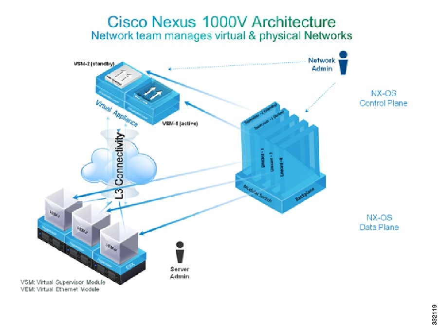
The VSM uses an external network fabric to communicate with the VEMs. The VSM runs the control plane protocols and configures the state of each VEM, but it never forwards packets. The physical NICs on the VEM server are the uplinks to the external fabric. VEMs switch traffic between the local virtual Ethernet ports that are connected to the VM vNICs but do not switch traffic to other VEMs. Instead, a source VEM switches packets to the uplinks that the external fabric delivers to the target VEM.
A single Cisco Nexus 1000V instance, including dual-redundant VSMs and managed VEMs, forms a switch domain. Each Cisco Nexus 1000V domain within a VMware vCenter Server must be distinguished by a unique integer called the domain identifier.
A single VSM can control up to 250 VEMs.
See the Cisco Nexus 1000V Resource Availability Reference for information about scale limits.
The Cisco Nexus 1000V architecture is shown in the following figure.
Information About the Virtual Ethernet Module
Each hypervisor is embedded with one VEM that replaces the virtual switch by performing the following functions:
-
Advanced networking and security
-
Switching between directly attached VMs
-
Uplinking to the rest of the network
Note |
Only one version of the VEM can be installed on an ESX/ESXi host at any time. |
Note |
Cisco Nexus 1000V VEM does not support ESXi custom TCP/IP stack and control traffic through the custom TCP/IP stack. |
In the Cisco Nexus 1000V, the traffic is switched between VMs locally at each VEM instance. Each VEM also interconnects the local VM with the rest of the network through the upstream access-layer network switch (blade, top-of-rack, end-of-row, and so forth). The VSM runs the control plane protocols and configures the state of each VEM accordingly, but it never forwards packets.
In the Cisco Nexus 1000V, the module slots are for the primary module 1 and secondary module 2. Either module can act as active or standby. The first server or host is automatically assigned to module 3. The network interface card (NIC) ports are 3/1 and 3/2 (vmnic0 and vmnic1 on the ESX/ESXi host). The ports to which the virtual NIC interfaces connect are virtual ports on the Cisco Nexus 1000V where they are assigned with a global number.
Information About VSM-to-VEM Communication
The VSM and the VEM can communicate over a Layer 2 network or a Layer 3 network. These configurations are referred to as Layer 2 or Layer 3 control modes.
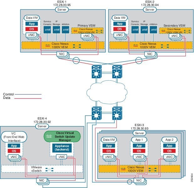
Layer 3 Control Mode
Layer 3 control mode is the preferred method of communication between the VSM and the VEMs. In Layer 3 control mode, the VEMs can be in a different subnet than the VSM and from each other. Active and standby VSM control ports should be Layer 2 adjacent. These ports are used to communicate the HA protocol between the active and standby VSMs.
Each VEM needs a designated VMkernel NIC interface that is attached to the VEM that communicates with the VSM. This interface, which is called the Layer 3 Control vmknic, must have a system port profile applied to it (see System Port Profiles and System VLANs), so the VEM can enable it before contacting the VSM.
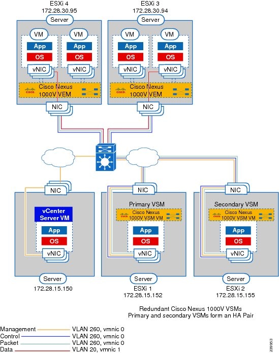
For a sample topology diagram, see Topology for Layer 3 Control Mode.
For more information about Layer 3 control mode, see the “Configuring the Domain” chapter in the Cisco Nexus 1000V System Management Configuration Guide.
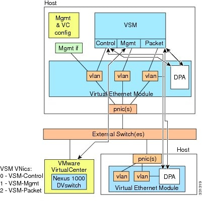
Layer 2 Control Mode
In Layer 2 control mode, the VSM and VEMs are in the same subnet. You can install the VSM and VEMs on different ESXi hosts or on the same ESXi host. This figure shows a VSM and VEM that are running on the same host in Layer 2 control mode.
For a sample topology diagram showing Layer 2 control mode, see Topology for Layer 2 Control Mode.

 Feedback