- Index
- New and Changed Information
- Preface
-
- Configuring and Managing VSANs
- SAN Device Virtualization
- Creating Dynamic VSANs
- Configuring Inter-VSAN Routing
- Configuring and Managing Zones
- Distributing Device Alias Services
- Configuring Fibre Channel Routing Services and Protocols
- Dense Wavelength Division Multiplexing
- Managing FLOGI, Name Server, FDMI, and RSCN Databases
- Discovering SCSI Targets
- Configuring FICON
- Advanced Features and Concepts
-
- Configuring FIPS
- Configuring Users and Common Roles
- Configuring SNMP
- Configuring RADIUS and TACACS+
- Configuring IPv4 Access Control Lists
- Configuring Certificate Authorities and Digital Certificates
- Configuring IPsec Network Security
- Configuring FC-SP and DHCHAP
- Configuring Port Security
- Configuring Fabric Binding
- Launching Fabric Manager in Cisco SAN-OS Releases Prior to 3.2(1)
- Cisco Fabric Manager Unsupported Feature List
- Interface Nonoperational Reason Codes
- Managing Cisco FabricWare
- Fabric Manager Web Services
Cisco MDS 9000 Family Fabric Manager Configuration Guide
Bias-Free Language
The documentation set for this product strives to use bias-free language. For the purposes of this documentation set, bias-free is defined as language that does not imply discrimination based on age, disability, gender, racial identity, ethnic identity, sexual orientation, socioeconomic status, and intersectionality. Exceptions may be present in the documentation due to language that is hardcoded in the user interfaces of the product software, language used based on RFP documentation, or language that is used by a referenced third-party product. Learn more about how Cisco is using Inclusive Language.
- Updated:
- February 6, 2008
Chapter: Configuring High Availability
Configuring High Availability
The Cisco MDS 9500 Series of multilayer directors support application restartability and nondisruptive supervisor switchability. The switches are protected from system failure by redundant hardware components and a high availability software framework.
This chapter includes the following sections:
•![]() Synchronizing Supervisor Modules
Synchronizing Supervisor Modules
About High Availability
The high availability (HA) software framework provides the following:
•![]() Ensures nondisruptive software upgrade capability. See Chapter 15, "Software Images."
Ensures nondisruptive software upgrade capability. See Chapter 15, "Software Images."
•![]() Provides redundancy for supervisor module failure by using dual supervisor modules.
Provides redundancy for supervisor module failure by using dual supervisor modules.
•![]() Performs nondisruptive restarts of a failed process on the same supervisor module. A service running on the supervisor modules and on the switching module tracks the HA policy defined in the configuration and takes action based on this policy. This feature is also available in switches in the Cisco MDS 9200 Series and the Cisco MDS 9100 Series.
Performs nondisruptive restarts of a failed process on the same supervisor module. A service running on the supervisor modules and on the switching module tracks the HA policy defined in the configuration and takes action based on this policy. This feature is also available in switches in the Cisco MDS 9200 Series and the Cisco MDS 9100 Series.
•![]() Protects against link failure using the PortChannel (port aggregation) feature. This feature is also available in switches in the Cisco MDS 9200 Series and in the Cisco MDS 9100 Series. See Chapter 23, "Configuring PortChannels."
Protects against link failure using the PortChannel (port aggregation) feature. This feature is also available in switches in the Cisco MDS 9200 Series and in the Cisco MDS 9100 Series. See Chapter 23, "Configuring PortChannels."
•![]() Provides management redundancy using the Virtual Router Redundancy Protocol (VRRP). This feature is also available in switches in the Cisco MDS 9200 Series and in the Cisco MDS 9100 Series.
Provides management redundancy using the Virtual Router Redundancy Protocol (VRRP). This feature is also available in switches in the Cisco MDS 9200 Series and in the Cisco MDS 9100 Series.
See the "Virtual Router Redundancy Protocol" section on page 51-8
•![]() Provides switchovers if the active supervisor fails. The standby supervisor, if present, takes over without disrupting storage or host traffic.
Provides switchovers if the active supervisor fails. The standby supervisor, if present, takes over without disrupting storage or host traffic.
Directors in the Cisco MDS 9500 Series have two supervisor modules (sup-1 and sup-2) in slots 5 and 6 (Cisco MDS 9509 and 9506 Switches) or slots 7 and 8 (Cisco MDS 9513 Switch). When the switch powers up and both supervisor modules are present, the supervisor module that comes up first enters the active mode and the supervisor module that comes up second enters the standby mode. If both supervisor modules come up at the same time, sup-1 becomes active. The standby supervisor module constantly monitors the active supervisor module. If the active supervisor module fails, the standby supervisor module takes over without any impact to user traffic.

Note ![]() For high availability, you need to connect the ethernet port for both active and standby supervisors to the same network or virtual LAN. The active supervisor owns the one IP address used by these ethernet connections. On a switchover, the newly activated supervisor takes over this IP address.
For high availability, you need to connect the ethernet port for both active and standby supervisors to the same network or virtual LAN. The active supervisor owns the one IP address used by these ethernet connections. On a switchover, the newly activated supervisor takes over this IP address.
Switchover Mechanisms
Switchovers occur by one of the following two mechanisms:
•![]() The active supervisor module fails and the standby supervisor module automatically takes over.
The active supervisor module fails and the standby supervisor module automatically takes over.
•![]() You manually initiate a switchover from an active supervisor module to a standby supervisor module.
You manually initiate a switchover from an active supervisor module to a standby supervisor module.
Once a switchover process has started another switchover process cannot be started on the same switch until a stable standby supervisor module is available.

HA Switchover Characteristics
An HA switchover has the following characteristics:
•![]() It is stateful (nondisruptive) because control traffic is not impacted.
It is stateful (nondisruptive) because control traffic is not impacted.
•![]() It does not disrupt data traffic because the switching modules are not impacted.
It does not disrupt data traffic because the switching modules are not impacted.
•![]() Switching modules are not reset.
Switching modules are not reset.
Initiating a Switchover
To manually initiate a switchover from an active supervisor module to a standby supervisor module, reset the active supervisor module using Device Manager. Once the switchover process has started, another switchover process cannot be started on the same switch until a stable standby supervisor module is available.
To perform a switchover using Device Manager, follow these steps:
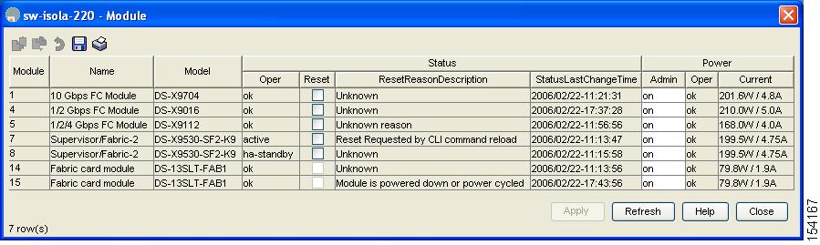
Step 1 ![]() Ensure that an HA switchover is possible by selecting Physical > Modules to verify the presence of multiple modules.
Ensure that an HA switchover is possible by selecting Physical > Modules to verify the presence of multiple modules.
You see the screen shown in Figure 17-1.
Figure 17-1 Modules Screen Shows Current Supervisor
Step 2 ![]() Select Admin > Reset Switch on the main Device Manager screen.
Select Admin > Reset Switch on the main Device Manager screen.
Figure 17-2 Reset Switch Dialog Box
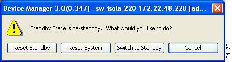
Step 3 ![]() Click Switch to Standby.
Click Switch to Standby.
Switchover Guidelines
Be aware of the following guidelines when performing a switchover:
•![]() When you manually initiate a switchover, system messages indicate the presence of two supervisor modules.
When you manually initiate a switchover, system messages indicate the presence of two supervisor modules.
•![]() A switchover can only be performed when two supervisor modules are functioning in the switch.
A switchover can only be performed when two supervisor modules are functioning in the switch.
•![]() The modules in the chassis are functioning as designed.
The modules in the chassis are functioning as designed.
Process Restartability
Process restartability provides the high availability functionality in Cisco MDS 9000 Family switches. It ensures that process-level failures do not cause system-level failures. It also restarts the failed processes automatically. This vital process functions on infrastructure that is internal to the switch.
See the "Displaying System Processes" section on page 68-1.
Synchronizing Supervisor Modules
The running image is automatically synchronized in the standby supervisor module by the active supervisor module. The boot variables are synchronized during this process.
The standby supervisor module automatically synchronizes its image with the running image on the active supervisor module.
See the "Replacing Modules" section on page 15-17.
The following conditions identify when automatic synchronization is possible:
•![]() If the internal state of one supervisor module is Active with HA standby and the other supervisor module is HA-standby, the switch is operationally HA and can do automatic synchronization.
If the internal state of one supervisor module is Active with HA standby and the other supervisor module is HA-standby, the switch is operationally HA and can do automatic synchronization.
•![]() If the internal state of one of the supervisor modules is none, the switch cannot do automatic synchronization.
If the internal state of one of the supervisor modules is none, the switch cannot do automatic synchronization.
Table 17-1 lists the possible values for the redundancy states.
Table 17-2 lists the possible values for the supervisor module states.
Table 17-3 lists the possible values for the internal redundancy states.
|
|
|
|---|---|
HA standby |
The HA switchover mechanism in the standby supervisor module is enabled (see the "HA Switchover Characteristics" section). |
Active with no standby |
A switchover is possible. |
Active with HA standby |
The active supervisor module in the switch is ready to be configured. The standby module is in the HA-standby state. |
Shutting down |
The switch is being shut down. |
HA switchover in progress |
The switch is in the process of changing over to the HA switchover mechanism. |
Offline |
The switch is intentionally shut down for debugging purposes. |
HA synchronization in progress |
The standby supervisor module is in the process of synchronizing its state with the active supervisor modules. |
Standby (failed) |
The standby supervisor module is not functioning. |
Active with failed standby |
The active supervisor module and the second supervisor module is present but is not functioning. |
Other |
The switch is in a transient state. If it persists, call TAC. |
 Feedback