Cisco MDS 9700 Series Multilayer Directors Hardware Installation Guide
Bias-Free Language
The documentation set for this product strives to use bias-free language. For the purposes of this documentation set, bias-free is defined as language that does not imply discrimination based on age, disability, gender, racial identity, ethnic identity, sexual orientation, socioeconomic status, and intersectionality. Exceptions may be present in the documentation due to language that is hardcoded in the user interfaces of the product software, language used based on RFP documentation, or language that is used by a referenced third-party product. Learn more about how Cisco is using Inclusive Language.
High humidity can cause moisture to seep into the switch. Moisture can cause corrosion of internal components and degradation
of properties such as electrical resistance, thermal conductivity, physical strength, and size. The switch is rated to operate
at 8 to 80 percent relative humidity, with a humidity gradation of 10 percent per hour.
The switch can withstand from 5 to 90 percent relative humidity. Buildings in which the climate is controlled by air-conditioning
in the warmer months and by heat during the colder months usually maintain an acceptable level of humidity for the switch
equipment. However, if the switch is located in an unusually humid location, you should use a dehumidifier to maintain the
humidity within an acceptable range.
Altitude Requirements
If you operate a switch at a high altitude (low pressure), the efficiency of forced and convection cooling is reduced and
can result in electrical problems that are related to arcing and corona effects. This condition can also cause sealed components
with internal pressure, such as electrolytic capacitors, to fail or to perform at a reduced efficiency. This switch is rated
to operate at altitudes from –500 to 13,123 feet (–152 to 4,000 meters). You can store the switch at altitudes of –1,000 to
30,000 feet (–305 to 9,144 meters).
Dust and Particulate Requirements
Exhaust fans cool power supplies and system fan modules cool switches by drawing in air and exhausting air out through various
openings in the chassis. However, fans also ingest dust and other particles, causing contaminant buildup in the switch and
increased internal chassis temperature. A clean operating environment can greatly reduce the negative effects of dust and
other particles, which act as insulators and interfere with the mechanical components in the switch.
Note
If you are using this switch in a non-clean environment, you can order and install optional air filters. These air filters
require that you also order the optional front door for the chassis.
In addition to regular cleaning, follow these precautions to avoid contamination of your switch:
Do not permit smoking near the switch.
Do not permit food or drink near the switch.
Minimizing Electromagnetic and Radio Frequency Interference
Electromagnetic interference (EMI) and radio frequency interference (RFI) from the switch can adversely affect other devices
such as radio and television (TV) receivers operating near the switch. Radio frequencies that emanate from the switch can
also interfere with cordless and low-power telephones. Conversely, RFI from high-power telephones can cause spurious characters
to appear on the switch monitor.
RFI is defined as any EMI with a frequency above 10 kHz. This type of interference can travel from the switch to other devices
through the power cable and power source or through the air like transmitted radio waves. The Federal Communications Commission
(FCC) publishes specific regulations to limit the amount of EMI and RFI that can be emitted by computing equipment. Each switch
meets these FCC regulations.
To reduce the possibility of EMI and RFI, follow these guidelines:
Cover all open expansion slots with a metal filler.
Always use shielded cables with metal connector shells for attaching peripherals to the switch.
When wires are run for any significant distance in an electromagnetic field, interference can occur between the field and
the signals on the wires and cause the following implications:
Bad wiring can result in radio interference emanating from the plant wiring.
Strong EMI, especially when it is caused by lightning or radio transmitters, can destroy the signal drivers and receivers
in the chassis and even create an electrical hazard by conducting power surges through lines into equipment.
Note
To predict and prevent strong EMI, you might need to consult experts in radio frequency interference (RFI).
The wiring is unlikely to emit radio interference if you use twisted-pair cable with a good distribution of grounding conductors.
If you exceed the recommended distances, use a high-quality twisted-pair cable with one ground conductor for each data signal
when applicable.
If the wires exceed the recommended distances, or if wires pass between buildings, give special consideration to the effect
of a lightning strike in your vicinity. The electromagnetic pulse caused by lightning or other high-energy phenomena can easily
couple enough energy into unshielded conductors to destroy electronic switches. You may want to consult experts in electrical
surge suppression and shielding if you had similar problems in the past.
Shock and Vibration Requirements
The switch is being shock- and vibration-tested for operating ranges, handling, and earthquake standards to Network Equipment
Building Standards (NEBS) Zone 4 per GR-63-Core.
Grounding Requirements
The switch is sensitive to variations in voltage supplied by the power sources. Overvoltage, undervoltage, and transients
(or spikes) can erase data from the memory or cause components to fail. To protect against these types of problems, ensure
that there is an earth-ground connection for the switch. You can connect the grounding pad on the switch either directly to
the earth-ground connection or to a fully bonded and grounded rack.
You must provide the grounding cable to make this connection but you can connect the grounding wire to the switch using a
grounding lug that ships with the switch. Size the grounding wire to meet local and national installation requirements. Depending
on the power supply and system, a 12 AWG to 6 AWG copper conductor is required for U.S. installations (for those installations,
we recommend that you use commercially available 6 AWG wire). The length of the grounding wire depends on the proximity of
the switch to proper grounding facilities.
Note
You automatically ground the AC power supplies when you connect them to a power source, but you cannot ground a 3-kW DC power
supply. You must connect the chassis to the facility earth ground.
Planning for Power Requirements
To plan for the power requirements of a switch, you must determine each of the following:
Power requirements of the switch
Minimum number of power supplies required to power the switch and its components
Power mode to use and the number of additional power supplies required for that mode
You must also ensure that the circuit used for the switch is dedicated to the switch to minimize the possibility of circuit
failure.
When you know the amount of power that is required for operations (available power) and redundancy (reserve power), you can
plan for the required number of input power receptacles with reach of the switch location.
Power Modes Overview
You can configure one of the following power modes to either use the combined power provided by the installed power supply
units (no power redundancy) or to provide power redundancy when there is a power loss:
Combined Mode
This mode allocates the combined power of all power supplies to active power for switch operations. This mode does not allocate
reserve power for power redundancy in case of power outages or power supply failures.
Power supply redundancy mode (N+1)
This mode allocates one power supply as a reserve power supply in case an available power supply fails. The remaining power
supplies are allocated for available power. The reserve power supply must be at least as powerful as the most powerful power
supply in the available pool to potentially replace the full power output of the failed power supply in the worst case. Because
it is impossible to predict which power supply may fail, we recommend provisioning the system with power supplies of equal
rating. This way the output of any power supply that fails can be replaced by the remaining power supplies.
For example, a system with four 3-kW power supplies in N+1 redundancy mode has a total of 12-kW. 9-kW are allocated to the
available power pool and 3-kW are reserved. If any of the power supplies fail enough power is reserved that the remaining
power supplies can still meet the 9-kW commitment.
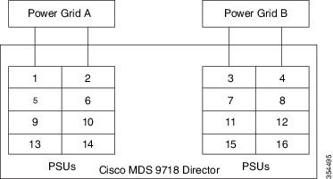
Input grid redundancy mode (grid redundancy)
In this mode half of the power supply's output is allocated to the reserve power pool and half to the available power pool.
This provides the system with enough reserve power in the case of 50% of the power supplies failing, as when a power grid
fails. The system logically allocates the left two columns of PSU bays to Grid A and sums the output power of operational
PSUs. It does the same for the right two columns (Grid B) and uses the minimum of the two as the available power pool. To
utilize maximum power the sum of power supply outputs of Grid A and Grid B PSU bays must be equal.
For example, a system with four 3-kW PSUs in Grid A bays and three 3-kW PSUs in Grid B bays and in grid redundancy mode has
12-kW available from Grid A and 9-kW from Grid B. The minimum of the two grids is 9-kW so 9-kW is allocated to the available
power pool and 9-kW are reserved. If either grid fails enough power is reserved that the remaining power supplies can still
meet the 9-kW commitment. The output of the fourth PSU in Grid A is not considered in the calculations although it provides
power.
Full redundancy mode
This mode supports both grid redundancy or N+1 redundancy. 50% of the power supply output is allocated to the reserve pool
and the other 50% of the power supply outputs are allocated to the available power pool. The reserved power may be used to
backup either single power supply failures or a grid failure.
For example, a system with six 3-kW power supplies in grid redundancy mode has a total of 18-kW. 9-kW are allocated to the
available power pool and 9-kW are allocated to the reserve pool. If a grid failure occurs (half of the power supplies lose
power) the full reserve power pool is available to meet the 9-kW commitment. Otherwise, as single power supplies fail power
is allocated to the available pool from the remaining reserve power pool until the reserve power pool is exhausted.
Note
Once a single power supply has failed in this mode, grid redundancy is no longer available.
The following figure shows how to connect power supplies in a Cisco MDS 9718 for grid redundancy.
Figure 1. Cisco MDS 9718 Grid-PSU Connections
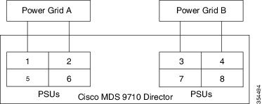
The following figure shows how to connect power supplies in a Cisco MDS 9710 for grid redundancy.
Figure 2. Cisco MDS 9710 Grid-PSU Connections
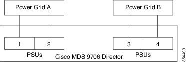
The following figure shows how to connect power supplies in a Cisco MDS 9706 for grid redundancy.
Figure 3. Cisco MDS 9706 Grid-PSU Connections
Rack and Cabinet Requirements
This section provides the requirements for the following type of racks, assuming an external ambient air temperature range
of 32°F to 104°F (0 to 40°C):
General Requirements for Open Four-Post Racks
The rack must be a standard 19-inch four-post EIA rack, with mounting rails that conform to English universal hole spacing
per section 1 of ANSI/EIA-310-D-1992. See the Clearance Requirements for Cisco MDS 9700 Series Directors section.
General Rack and Cabinet Requirements for Cisco MDS 9700 Series Directors
You can install the following types of racks or cabinets for your switch:
Standard perforated-doors cabinets
Solid-walled cabinets with a roof fan module (bottom to top cooling)
Standard open four-post Telco racks
Standard open two post Telco racks
Note
Cisco MDS 9700 Series Directors are compatible with Cisco racks (such as Cisco R42612) and PDUs.
Use a standard 19 inch, four post Electronic Industries Alliance (EIA) cabinet or rack with mounting rails that conform to
English universal hole spacing per section 1 of the ANSI/EIA-310-D-1992 standard.
The depth of a four post rack or a cabinet must be 24 to 32 inches (61.0 to 81.3 cm) between the front and rear mounting vertical
rails.
Ensure that the airflow and cooling are adequate and there is sufficient clearance around the air vents on the switch, as
described in
The rack must have sufficient vertical clearance for the chassis and any desired clearance for the installation process. The
shelf brackets are 2 RU, and they are built and installed so that they do not add up to the total chassis vertical clearance
of 14 RU.
The front and rear doors of enclosed racks must have at least 60% open area perforation pattern.
Additionally, you must consider the following site requirements for the rack:
Power receptacles must be located within reach of the power cords used with the switch.
AC power supplies
Power cords for 3-kW AC power supplies are 8 to 12 feet (2.5 to 4.3 m) long.
DC power supplies
Power cords for 3.0-kW DC power supplies are supplied and dimensioned by the customer.
HVAC/HVDC power supplies
Power cords for 3.5-kW HVAC/HVDC power supplies are 14 feet (4.26 m) long.
Where necessary, have a seismic rating of Network Equipment Building Standards (NEBS) Zone 3 or Zone 4, per GR-63-CORE.
Rack and Cabinet Requirements for the Cisco MDS 9718 Chassis
To correctly install the switch in a cabinet that is located in a hot-aisle/cold-aisle environment, you should fit the cabinet
with baffles to prevent exhaust air from recirculating into the chassis air intake. Work with your cabinet vendors to determine
which of their cabinets meet the following requirements or see the Cisco Technical Assistance Center (TAC) for recommendations:
The height of the rack or cabinet must accommodate the 25 RU (43.75 inches or 111.1 cm) height of the switch and its bottom
support bracket.
Minimum gross load rating of 2000 lb (907.2 kg) (static load rating) if supporting two switches.
Rack and Cabinet Requirements for the Cisco MDS 9710 Chassis
The rack must meet the following requirements:
The minimum vertical rack space per chassis is 24.5 inches (62.2 cm) or 14 RU.
The width between the mounting rails must be at least 17.75 inches (45.1 cm). For four-post EIA racks, this is the distance
between the two front rails and rear rails.
To correctly install the switch in a cabinet that is located in a hot-aisle/cold-aisle environment, you should fit the cabinet
with baffles to prevent exhaust air from recirculating into the chassis air intake. Work with your cabinet vendors to determine
which of their cabinets meet the following requirements or see the Cisco Technical Assistance Center (TAC) for recommendations:
The height of the rack or cabinet must accommodate the 14-RU (24.5 inches or 62.2 cm) height of the switch and its bottom
support bracket.
Minimum gross load rating of 2000 lb (907.2 kg) (static load rating) if supporting three switches.
Rack and Cabinet Requirements for the Cisco MDS 9706 Chassis
To correctly install the switch in a cabinet that is located in a hot-aisle/cold-aisle environment, you should fit the cabinet
with baffles to prevent exhaust air from recirculating into the chassis air intake. Work with your cabinet vendors to determine
which of their cabinets meet the following requirements or see the Cisco Technical Assistance Center (TAC) for recommendations:
The height of the rack or cabinet must accommodate the 9 RU (15.75 inches or 40.0 cm) height of the switch and its bottom
support bracket. The bottom support bracket ships as a part of the accessory kit for the switch.
Minimum gross load rating of 2000 lb (907.2 kg) (static load rating) if supporting four switches.
Clearance Requirements for Cisco MDS 9700 Series Directors
You must provide adequate clearance between the chassis and any other rack, device, or structure so that you can properly
install the chassis, route cables, provide airflow, and maintain the switch. Ensure that the following clearance requirements
are met:
7 inches (17.78 cm) between the front of chassis and inside of cabinet.
34 inches (86.36 cm) [40 inches recommended (101 cm)] in front of the cabinet so that a fully loaded 34 inches (86.36 cm)
chassis box can be moved.
2 inches (5.08 cm) for module handles.
3 inches (7.62 cm) between the rear of the chassis and the inside of the cabinet, that is, the perforated rear door (required
for airflow in the cabinet if used).
25 inches (63.5 cm) outside of the cabinet to remove fabric modules.
No clearance is required between the chassis and the sides of the rack or cabinet (no side airflow).
Clearance required for cables that connect to as many as 400 ports (in addition to the cabling required for other devices
in the same rack). These cables must not block access to any removable chassis modules or block airflow into or out of the
chassis. Route the cables through the cable management frames on the left and right sides of the chassis.
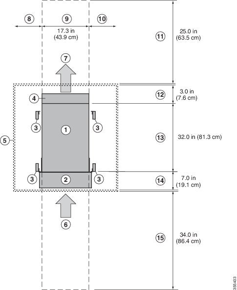
The following figure illustrates the front, rear, and side clearance requirements for Cisco MDS 9700 Series Directors.
Figure 4. Clearance Requirements for Cisco MDS 9700 Series Directors (Top View)
Table 1. Cisco MDS 9700 Clearance Requirements
1
Chassis
2
Cable Management Frames
3
Vertical rack-mount posts and rails
4
Area used for fan tray handles at the rear of the chassis (allow 2 inches [5 cm])
5
Nearest object or inside of cabinet (no side clearance required)
6
Fibre Channel ports.
Air intake from the cold aisle for all modules and power supplies
7
Air exhaust to the hot aisle for all modules and power supplies
8
No left side clearance required (no airflow on left side)
9
Chassis width
10
No right side clearance required (no airflow on right side)
11
Rear service clearance required to replace fan trays and fabric modules
12
Airflow clearance area required at the rear of the chassis within the cabinet (if a cabinet is used)
13
Chassis depth
14
Clearance required between the front of the chassis and the inside of the cabinet (if used) or the edge of the cold aisle
(if no cabinet) for the cable management frames and the optional front doors
15
Front service clearance required for installing the chassis and replacing the modules on the front of the chassis
Rack-Mounting Guidelines
Caution
If the rack is on wheels, ensure that the brakes are engaged or the rack is otherwise stabilized.
If installing this kit in an EIA rack, attach the switch to all four rack-mounting rails; the EIA rails may not be thick
enough to prevent flexing of the shelf brackets if only two rails are used.
Before Installing the Rack-Mount Support Brackets
Before installing the rack-mount support brackets for the Cisco MDS 9700 Series, check the contents of your kit. The table
below, lists the contents of the shelf bracket kit.
Table 2. Contents of Rack-Mount Support Brackets Kit
Quantity
Part Description
2
Bottom support brackets
20
12-24 x 3/4-in. Phillips screws
20
M6 x 19 mm Phillips binder-head screws
20
10-32 x 3/4-inch screws
Installing and Removing the Brackets
This section provides information on how to install and remove brackets.
Before installing the shelf brackets, check the contents of your kit. The table below, lists the contents of the shelf bracket
kit.
Table 3. Contents of Shelf Bracket Kit
Quantity
Part Description
2
Slider brackets
2
Shelf brackets
1
Crossbar
2
10-32 x 3/8-in. Phillips pan-head screws
16
12-24 x 3/4-in. Phillips screws
16
10-24 x 3/4-in. Phillips screws
Required Equipment
You need the following equipment for this installation:
Number 2 Phillips screwdriver
Tape measure and level (to ensure shelf brackets are level)
Installing the Cisco MDS 9700 Series Shelf Bracket Kit into a Rack
Use this procedure to install the shelf brackets in a rack.
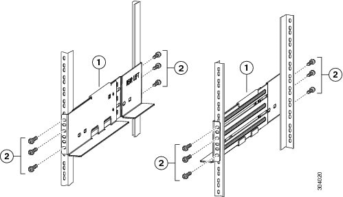
The following figure shows the installation of the Cisco MDS 9700 Series Shelf Bracket Kit into a four-post rack.
Figure 5. Installing the Shelf Bracket Kit into a Rack
Procedure
Step 1
Position a shelf bracket inside the rack-mounting rails. Align the screw holes at the front of the shelf bracket with the
holes in the front rack-mounting rail, and then attach the shelf bracket to the front rack-mounting rail using a minimum of
three (M6, 12-32 or 12-24) screws.
Step 2
Align the screw holes at the back of the shelf bracket with the holes in the back rack-mounting rail, and then attach the
shelf bracket to the back rack-mounting rail using a minimum three (M6, 12-32 or 12-24) screws.
Step 3
Verify that the shelf brackets are at the same height (using the level or tape measure as desired).
Installing the Switch on the Brackets
This section provides information on how to install the switch on the rack-mount support brackets and on the shelf brackets
and includes the following subsections:
Installing the Switch on the Rack-Mount Support Brackets
Use this procedure to install the switch on top of the rack-mount support brackets.
Before you begin
This section provides general instructions for installing the switch on top of the rack-mount support brackets. For detailed
installation instructions, see the Rack Mounting Guidelines section, covered earlier in this chapter.
Warning
This unit is intended for installation in restricted access areas. A restricted access area can be accessed only through the
use of a special tool, lock and key, or other means of security. Statement 1017
Only trained and qualified personnel should be allowed to install, replace, or service this equipment. Statement 1030
Note
Before you install, operate, or service the system, see the Regulatory Compliance and Safety Information for the Cisco MDS 9000 Family for important safety information.
Procedure
Step 1
Verify that the rack-mount support brackets are level and securely attached to the rack-mounting rails, the support rack-mount
support brace is securely attached to the brackets, and the rack is stabilized.
Step 2
Slide a mechanical lift under the switch and lift the switch up onto the rack-mount support brackets, ensuring it is squarely
positioned.
Step 3
Attach the switch to the rack-mounting rails. See the
Caution
We recommend grounding the chassis, even if the rack is already grounded. There is a grounding pad with two threaded M4 holes
on the chassis for attaching a grounding lug.
The Cisco MDS 9700 Series Shelf Bracket Kit can be used to support the switch in a nonthreaded rack. This shelf bracket kit
can be used as a permanent support when installing a Cisco MDS 9700 Series Director in a rack that meets the requirements
listed in the Rack and Cabinet Requirements section.
Warning
This unit is intended for installation in restricted access areas. A restricted access area can be accessed only through the
use of a special tool, lock and key, or other means of security. Statement 1017
Only trained and qualified personnel should be allowed to install, replace, or service this equipment. Statement 1030
Note
Before you install, operate, or service the system, see the Regulatory Compliance and Safety Information for the Cisco MDS 9000 Family for important safety information.
Procedure
Step 1
Verify that the shelf brackets are level and securely attached to the rack-mounting rails, the crossbar is securely attached
to the shelf brackets, and the rack is stabilized.
Step 2
Slide the switch onto the shelf brackets, ensuring that it is squarely positioned.
Step 3
Attach the Cisco MDS 9700 Series switch to the rack-mounting rails. Slide the clip nuts over the holes on the nonthreaded
rails on the rack. These clip nuts provide the threading for the screws that will secure the chassis to the rack. Use the12
10-32 x 1/2 inch screws provided in this shelf bracket kit to secure the chassis to the rack.
Caution
We recommend that grounding the chassis, even if the rack is already grounded. There is a grounding pad with two threaded
M4 holes on the chassis for attaching a grounding lug.
Removing the Shelf Bracket Kit
Use this procedure to remove the shelf bracket kit.
The shelf bracket kit can be removed after the Cisco MDS 9700 Series switch has been installed in a two-post telco (only MDS
9706 Director) or four-post EIA rack, and the front rack-mount brackets are securely attached to the rack-mounting rails.
For additional support in an EIA rack, ensure that the C brackets on the Cisco MDS 9710 Switch are attached to the rear rack-mounting
rails.
Procedure
Step 1
Remove the screws fastening the slider brackets to the rear rack-mounting rails. Then slide the slider brackets out of the
shelf brackets.
Step 2
Remove the screws fastening the crossbar to the shelf brackets and remove the crossbar.
Step 3
Remove the screws fastening the shelf brackets to the front rack-mounting rails. Then remove the shelf brackets from the rack.


 Feedback