New and Changed Information
The following table provides an overview of the significant changes to the organization and features in this guide from the release the guide was first published to the current release. The table does not provide an exhaustive list of all changes made to the guide or the new features of the Cisco Cloud APIC.
|
Cloud APIC Release |
Feature or Change Description |
|---|---|
|
Release 5.0(2) |
First release of this document. |
|
Release 5.1(2) |
Support for third-party load balancers. |
Layer 4 to Layer 7 Services in Infra Tenant for Azure Sites
This document describes the workflow for Infra tenant configuration of multi-node service graphs with user defined routing (UDR).
Additional information about service graphs in cloud sites, such as specific features and use cases, is available in the Cloud APIC Azure User Guide. The information and procedures provided below are specific to deploying service graphs from Multi-Site Orchestrator.
Service Graphs
A service graph is used to represent a set of Layer 4 to Layer 7 service devices inserted between two or more Endpoint Groups (EPGs). EPGs can represent your applications running within a cloud (e.g. Cloud EPG), or internet (e.g. Cloud External EPG), or in other sites (e.g. on-premises or remote cloud sites).
A service graph in conjunction with contracts (and filters) is used to specify communication between two EPGs. The cloud APIC automatically derives security rules, such as network security groups (NSG) and application security groups (ASG), and forwarding routes using User Defined Routing (UDR) based on the policy specified in Contract and Service Graph.
By using a service graph, you can specify the policy once and deploy the service chain within regions or inter-regions. After the graph is configured, the Cloud APIC automatically configures the services according to the service function requirements that are specified in the service graph. The Cloud APIC also automatically configures the network according to the needs of the service function that is specified in the service graph, which does not require any change in the service device. For third-party firewalls, the configuration inside the device is not managed by cloud APIC.
Each time the graph is deployed, Cisco ACI takes care of changing the network configuration to enable the forwarding in the new logical topology.
Service Graph Devices
Multiple service graphs can be specified to represent different traffic flows or topologies. A service graph represents the network using the following elements:
-
Service Graph Nodes—A node represents a device, such as a load balancer or a firewall. Each device within the service graph may require one or more parameters and have one or more connectors.
-
Connectors—A connector enables input and output on a node.
Following combinations are possible with service graphs:
-
Same device can be used in multiple service graphs.
-
Same service graph can be used between multiple consumer and provider EPGs.
The following service graph devices are supported:
-
Azure Application Load Balancers (ALB)
-
Azure Network Load Balancers (NLB)
-
Unmanaged third-party firewall devices
-
Unmanaged third-party load balancers
Overlay-1 and Overlay-2 VRFs
The overlay-1 and overlay-2 VRFs are automatically created in the infra tenant for Cloud APIC. In the Azure portal, CIDRs and subnets from the overlay-1 and overlay-2 VRFs are deployed in the Azure cloud on the overlay-1 VNet. The overlay-2 VRF is used to hold additional CIDRs. You should not consider overlay-2 as a separate VNet.
Requirement for Separate VRFs in the Infra Hub
Prior to Release 5.0(2), the infra hub VNet was used to achieve transit routing functionality for inter-spoke communications within the site through CSRs in the hub, and to send VxLAN packets for EPG communication across sites.
There are situations where you might want to deploy a certain number of EPGs configured with shared services and layer 4 to layer 7 service graphs in a common hub that can be shared across spokes. In some situations, you might have multiple hub networks deployed separately (for example, for production, pre-production, and core services). You might want to deploy all of these hub networks in the same infra hub VNet (in the same infra cloud context profile), along with the existing cloud CSRs.
Thus, for these kind of requirements, you might need to split the hub VNet into multiple VRFs for network segmentation while keeping the security intact.
Infra Hub Services VRF (Overlay-2 VRF in the Infra VNet)
Beginning with Release 5.0(2), the overlay-2 VRF is now created in the infra tenant implicitly during the Cisco Cloud APIC bringup. In order to keep the network segmentation intact between the infra subnets used by the cloud site (for CSRs and network load balancers) and the user subnets deployed for shared services, different VRFs are used for infra subnets and user-deployed subnets:
-
Overlay-1: Used for infra CIDRs for the cloud infra, along with Cisco Cloud Services Routers (CSRs), the infra network load balancer, and the Cisco Cloud APIC
-
Overlay-2: Used for user CIDRs to deploy shared services, along with layer 4 to layer 7 service devices in the infra VNet (the overlay-1 VNet in the Azure cloud)
All the user-created EPGs in the infra tenant can only be mapped to the overlay-2 VRF in the infra VNet. You can add additional CIDRs and subnets to the existing infra VNet (the existing infra cloud context profile). They are implicitly mapped to overlay-2 VRF in the infra VNet, and are deployed in the overlay-1 VNet in the Azure cloud.
Prior to Release 5.0(2), any given cloud context profile would be mapped to a cloud resource of a specific VNet. All the subnets and associated route tables of the VNet would be have a one-to-one mapping with a single VRF. Beginning with Release 5.0(2), the cloud context profile of the infra VNet can be mapped to multiple VRFs (the overlay-1 and overlay-2 VRFs in the infra VNet).In the cloud, the subnet’s route table is the most granular entity for achieving network isolation. So all system-created cloud subnets of the overlay-1 VRF and the user-created subnets of the overlay-2 VRF will be mapped to separate route tables in the cloud for achieving the network segmentation.
 Note |
On Azure cloud, you cannot add or delete CIDRs in a VNet when it has active peering with other VNets. Therefore, when you need to add more CIDRs to the infra VNet, you need to first disable VNet peering in it, which removes all the VNet peerings associated with the infra VNet and causes traffic disruption. After adding new CIDRs to the infra VNet, you need to enable VNet peering again in the infra VNet. You do not have to disable VNet peering if you are adding a new subnet in an existing CIDR in the hub VNet. See Configuring VNET Peering for Cloud APIC for Azure for more information. |
Redirect Programming
Redirect programming depends on the classification of the destination EPG (tag-based or subnet-based):
-
For a subnet-based EPG, subnets of the destination EPGs are used to program redirects
-
For a tag-based EPGs, CIDRs of the destination VNet are used to program redirects
As a result of this, the redirect affects traffic from other EPGs going to the same destination in the redirect, even if the EPG is not part of the service graph with the redirect. Traffic from EPGs that are not part of the redirect will also get redirected to the service device.
The following table describes how redirect is programmed in different scenarios.
|
Consumer |
Provider |
Redirect on Consumer VNet |
Redirect on Provider VNet |
|---|---|---|---|
|
Tag-based |
Tag-based |
Redirect for the provider are the CIDRs of the provider's VNet |
Redirect for the consumer are the CIDRs of the consumer's VNet |
|
Tag-based |
Subnet-based |
Redirect for the provider are the subnets of the provider |
Redirect for the consumer are the CIDRs of the consumer's VNet |
|
Subnet-based |
Tag-based |
Redirect for the provider are the CIDRs of the provider's VNet |
Redirect for the consumer are the subnets of the consumer |
|
Subnet-based |
Subnet-based |
Redirect for the provider are the subnets of the provider |
Redirect for the consumer are the subnets of the consumer |
Redirect Policy
To support the Layer 4 to Layer 7 Service Redirect feature, a new redirect flag is now available for service device connectors. The following table provides information on the existing and new flags for the service device connectors.
|
ConnType |
Description |
|---|---|
|
redir |
This value means the service node is in redirect node for that connection. This value is only available or valid for third-party firewalls and Network Load Balancers. |
|
snat |
This value tells the service graph that the service node is performing source NAT on traffic. This value is only available or valid for the provider connector of third-party firewalls and only on the provider connector of a node. |
|
snat_dnat |
This value tells the service graph that the service node is performing both source NAT and destination NAT on traffic. This value is only available or valid for the provider connector of third-party firewalls and only on the provider connector of a node. |
|
none |
Default value. |
Spoke to Internet
In this use case, the consumer VNet (with consumer VMs) and the hub VNet are peered using VNet peering. A network load balancer is also deployed, fronting two firewalls for scaling. In this use case, the consumer VMs need access to the internet for a certain reason, such as patch updates. In the consumer VNet, the route table is modified to include a redirect for the internet in this case, and traffic is redirected to the NLB in front of firewalls in the hub VNet. Any traffic from this consumer that is part of the service graph that is going to the internet goes to the NLB as the next-hop. With VNet peering, traffic first goes to the NLB, then the NLB forwards the traffic to one of the firewalls in the back end. The firewalls also perform source network address translation (SNAT) when sending traffic to the internet.
Ensure that all the Layer 4 - Layer 7 devices used in this use case have dedicated subnets.
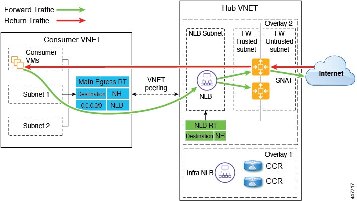
The following figure shows the packet flow for this use case.
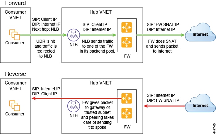
The following figure shows the service graph for this use case.

Spoke to Spoke
In this use case, traffic flows from spoke to spoke, through the hub firewall fronted by a hub NLB. Consumer endpoints are in the consumer VNet, and the provider VNet has VMs fronted by an internal NLB (or a third party load balancer). The egress route table is modified in the consumer and provider VNets so that traffic is redirected to the firewall device fronted by the NLB. Redirect is applied in both directions in this use case. The NLB must have a dedicated subnet in this case.
Ensure that all the Layer 4 - Layer 7 devices used in this use case have dedicated subnets.
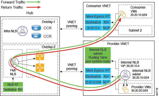
The following figure shows the packet flow for this use case.
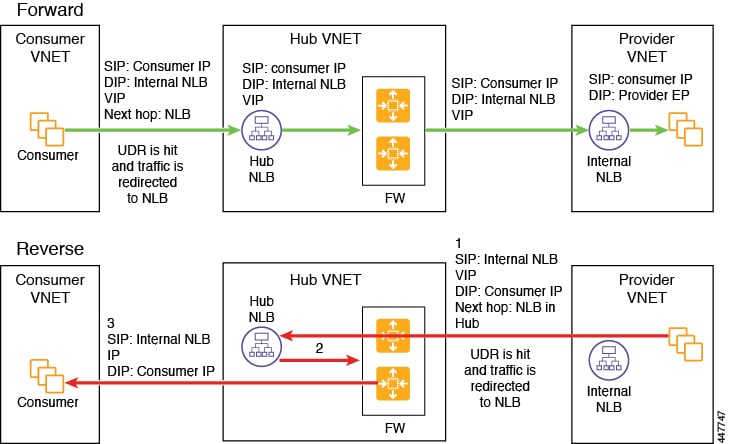
The following figure shows the service graph for this use case.

Inter-Region Spoke to Spoke
In this use case, both regions must have service devices,. The consumer VNet is in region 1, the provider is stretched across both regions (regions 1 and 2), and some endpoints are in region 1 and some endpoints are in region 2. Different redirects are programmed for local provider endpoints and for remote region endpoints. In this case, the firewall that is used will be the firewall that is closest to the provider endpoint side.
Ensure that all the Layer 4 - Layer 7 devices used in this use case have dedicated subnets.
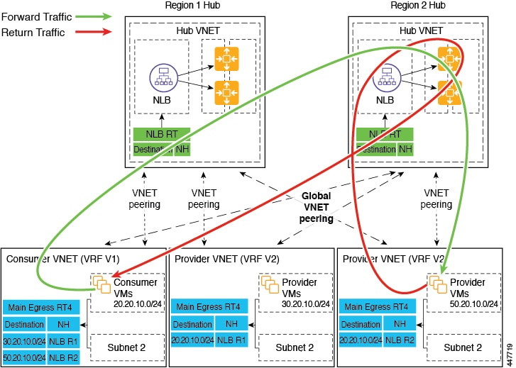
For example, consider the two subnets in the consumer VNet (VRF 1) egress route table (RT):
-
30.20.10.0/24 (NLB in region 1 [R1])
-
50.20.10.0/24 (NLB in region 2 [R2])
Assume the consumer wants to send traffic to the provider VMs 30.20.10.0/24, which are local to it. In that case, traffic will get redirected to the region 1 hub NLB and firewall, and will then go to the provider.
Now assume the consumer wants to send traffic to the provider VMs 50.20.10.0/24. In this case, the traffic will get redirected to the region 2 hub NLB and firewall, because that firewall is local to the provider endpoint.
The following figure shows the packet flow for this use case.
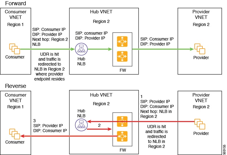
The following figure shows the service graph for this use case.

In the above use case, the provider VMs can also be front-ended by a cloud native or third party load balancer
Internet to Spoke (Inter-VRF)
In this use case, traffic coming from the internet needs to go through the firewall before hitting the provider endpoints. Redirect is not used in this use case.
 Note |
The general term "external load balancer" is used in this section because in this use case, the external load balancer could be either an NLB or an ALB or a third party load balancer. The following examples provide configurations using an ALB, but keep in mind that the external load balancer could be an NLB or a third party load balancer instead. |
The external load balancer exposes the service through VIP. Internet traffic is directed to that VIP, then external load balancers direct traffic to the firewalls in the backend pool (the external load balancers have the firewall's untrusted interface as its backend pool). The firewall performs SNAT and DNAT, and the traffic goes to the internal NLB VIP. The internal NLB then sends traffic to one of the provider endpoints.
Ensure that all the Layer 4 - Layer 7 devices used in this use case have dedicated subnets.
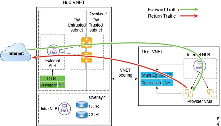
The following figure shows the packet flow for this use case.
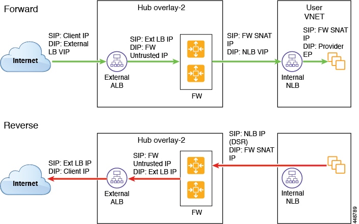
The following figure shows the service graph for this use case.

High Availability Support for Third Party Load Balancers
In this use case, traffic coming from the internet needs to go through the third party load balancer before hitting the provider endpoints. Redirect is not used in this use case.
The third party load balancer is configured as the backend pool of the NLB. Secondary IP addresses of the devices act as the target for the NLBs. You can choose to add either primary or secondary IP address (or both) as the target for the NLBs. The third party load balancer VMs are deployed in active-active mode only. Third party load balancers can not be used in active-standby high availability configuration.
Ensure that the third party load balancers and the network load balancers have dedicated subnets.
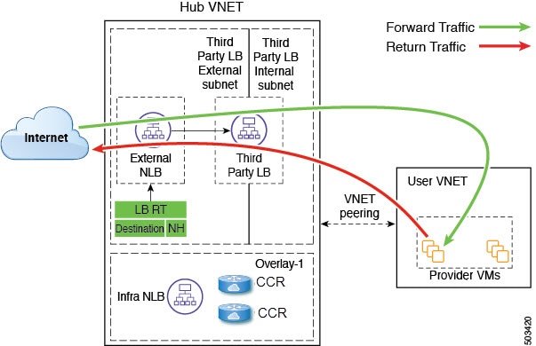
The following figure shows the service graph for this use case.

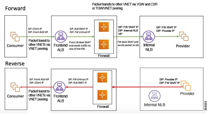
Consumer and Provider EPGs in Two Separate VNets
This use case is an example configuration with two VNets, with a consumer EPG and provider EPG in separate VNets.
-
A frontend ALB, firewall, and internal NLB are inserted between the consumer and provider EPGs.
-
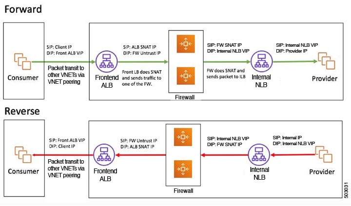
A consumer endpoint sends traffic to the frontend ALB VIP and it is forwarded to the firewall.
-
The firewall performs SNAT and DNAT, and the traffic flows to internal NLB VIP.
-
The internal NLB load balances the traffic to the backend provider endpoints.
In this use case, a third party load balancer can be used in place of the frontend ALB or an internal NLB.
Ensure that all the Layer 4 - Layer 7 devices used in this use case have dedicated subnets.
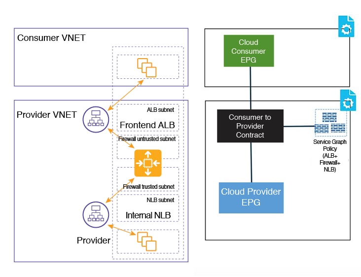
In the figure:
-
The consumer EPG is in a consumer VNet.
-
The provider EPG and all the service devices are in the provider VNet.
-
The application load balancer, network load balancer (or third party load balancer), and firewall need to have their own subnet in the VNet.
Packet flow for both the directions is shown in the following figure:
Hub VNet with Consumer and Provider EPGs in Two Separate VNets
This use case is an example configuration with three VNets: a hub VNet, and a consumer EPG and provider EPG in two separate VNets.
-
A frontend ALB and firewall are inserted within the hub VNet, which is between the consumer and provider EPGs.
-
An internal NLB is inserted in the provider EPG.
-
A consumer endpoint sends traffic to the frontend ALB VIP and it is forwarded to the firewall.
-
The firewall performs SNAT and DNAT, and the traffic flows to internal NLB VIP.
-
The internal NLB load balances the traffic to the backend provider endpoints.
In this use case, a third party load balancer can be used in place of the frontend ALB or an internal NLB.
Ensure that all the Layer 4 - Layer 7 devices used in this use case have dedicated subnets.
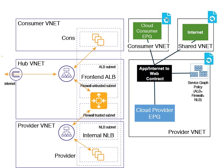
In the figure:
-
The consumer EPG is in a consumer VNet.
-
The provider EPG and the internal NLB are in the provider VNet.
-
The frontend ALB and firewall are in the hub VNet
-
The application load balancer, network load balancer (or third party load balancer), and firewall need to have their own subnet in the VNet.
Packet flow for both the direction is shown in the following figure:
Creating Service Graph Devices
This release of Multi-Site Orchestrator does not support creating service graph devices, so you must first create them from the Cloud APIC UI. This section describes the GUI workflow to create the device; specific device configuration are described in the Cloud APIC Azure User Guide.
Procedure
| Step 1 |
Log in to your Cloud APIC GUI. |
||
| Step 2 |
Create a new device 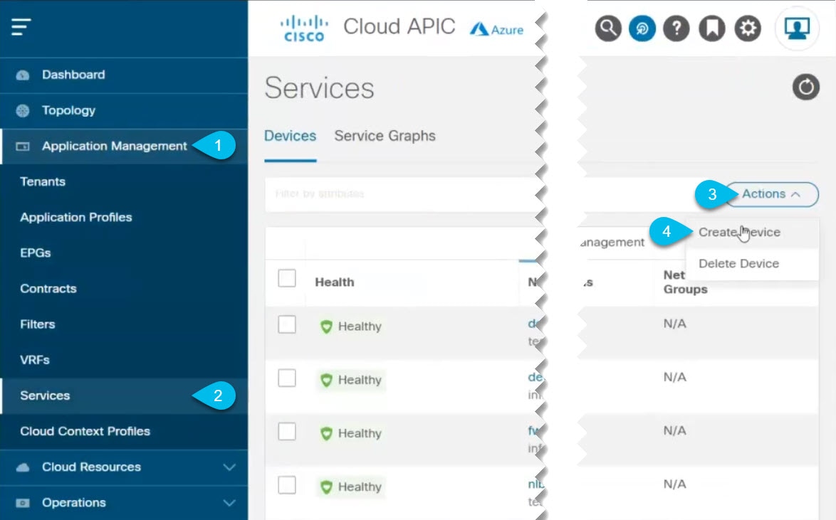
|
||
| Step 3 |
Create an Azure Application Load Balancers (ALB) device. If you are not creating an ALB, skip this step. |
||
| Step 4 |
Create an Azure Network Load Balancers (NLB) device. If you are not creating an NLB, skip this step. |
||
| Step 5 |
Create a Third-Party Firewall device. If you are not creating a third-party unmanaged device, skip this step. |
||
| Step 6 |
Create a Third-Party load balancer device. If you are not creating a third party load balancer, skip this step.
|
Guidelines and Limitations
-
ACI Multi-Site multi-cloud deployments support a combination of any two cloud sites (AWS, Azure, or both) and two on-premises sites for a total of four sites.
-
Infra tenant configurations are supported only for Azure cloud sites.
-
Infra tenant configurations are supported only for the two VRFs automatically created in the Cloud APIC.
The Layer 4 to Layer 7 services in the
infratenant are configured on theoverlay-2VRF which is implicitly created during the Cloud APIC setup. When configuring these use cases from the Multi-Site Orchestrator, you must import the existingoverlay-2VRF from the Cloud APIC. -
The Layer 4 to Layer 7 services is not supported across multiple sites.
Creating Schema and Template
This section describes how to create a new schema for the Infra tenant. The process is the same as when creating a typical
schema, with the exception that you can now choose the infra tenant.
Procedure
| Step 1 |
Log in to your Cisco Multi-Site Orchestrator GUI. |
| Step 2 |
Create a new Schema for the Infra Tenant. 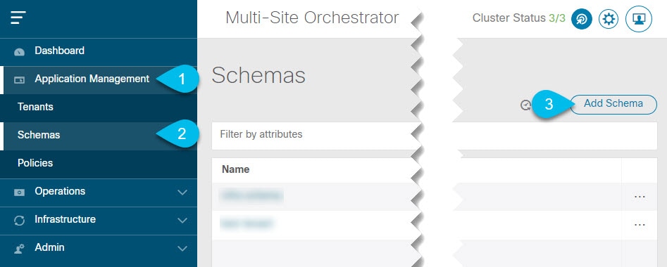
The Edit Schema window will open. |
| Step 3 |
Name the Schema and pick the Tenant. 
|
Associating Template with Sites
Use the following procedure to associate the template with the appropriate sites.
Procedure
|
Add the sites. 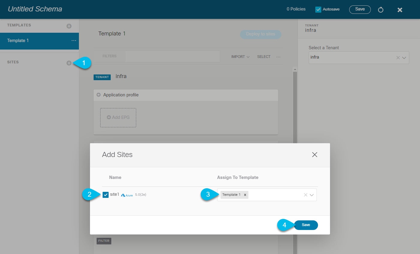
|
Importing overlay-2 VRF
When working with Infra tenant schemas, you cannot create new VRFs. This section describes how to import the overlay-2 VRF from the cloud site.
Procedure
| Step 1 |
Select the template and the |
| Step 2 |
Choose to import from the Cloud site. 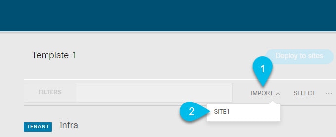
|
| Step 3 |
Choose the 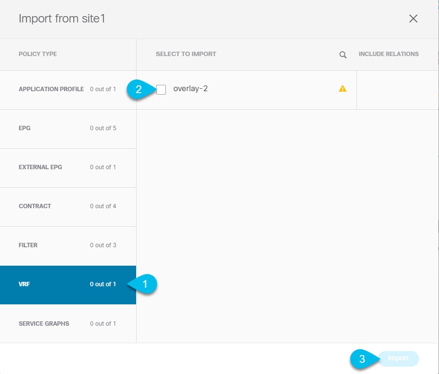 |
| Step 4 |
Repeat these steps for all sites associated with the template. If you plan to stretch the configuration between multiple Azure sites, you must import the |
Adding or Updating Overlay-2 CIDRs
After you deploy your Cloud APIC, you will see overlay-1 and overlay-2 VRFs in the Cisco Cloud APIC. However, only the overlay-1 will be created in the Azure portal. This is because overlay-2 is a logical extension of overlay-1 and is used to hold additional CIDRs that you may need when deploying firewalls or load balancers in the Infra VNet.
This section describes how to create new or modify existing CIDRs for the overlay-2 VRF.
Procedure
| Step 1 |
Navigate to the  |
| Step 2 |
Disable Hub Network Peering. If you simply need to add additional subnets to an existing CIDR or hub network peering is not enabled, skip this step. You need to disable VNet peering before adding new CIDRs or editing existing CIDRs in Once you have updated the CIDRs, you can then re-enable the VNet peerings. 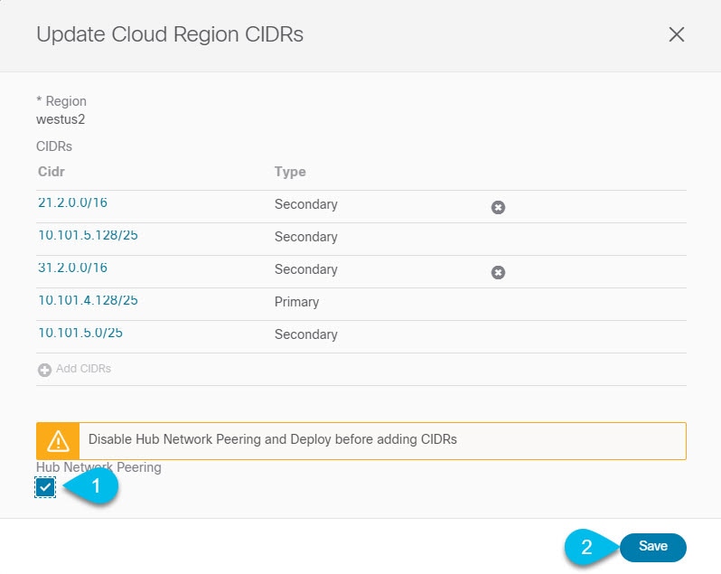 |
| Step 3 |
In the Update Cloud Region CIDRs screen, click Add CIDRs and provide the new CIDR information. You can add only secondary CIDRs. |
| Step 4 |
Re-enable Hub Network Peering. If you did not disable the Hub Network Peering at the start of these steps, skip this step. |
Creating Filter and Contract
This section describes how to create a contract and filters that will be used for the traffic going through the service graphs. If you plan to allow all traffic, you can skip this section.
Procedure
| Step 1 |
Create a filter. 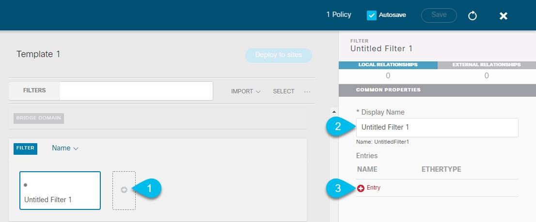
|
| Step 2 |
Provide the filter details. 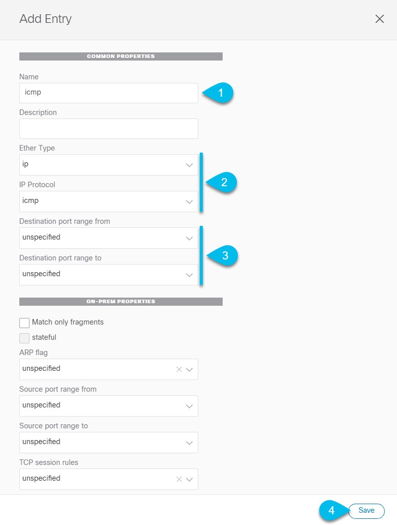 |
| Step 3 |
Create a contract |
| Step 4 |
Assign the filters to the contract |
Creating Consumer and Provider EPGs
This section describes how to create two cloud EPGs in the infra tenant. You will then establish a contract between them and attach the contract to a service graph so the traffic between the EPGs flows through the service graph nodes. If you have imported the EPGs from your cloud site, you can skip this section.
Procedure
| Step 1 |
Create an application profile.
|
| Step 2 |
Create an EPG.
|
| Step 3 |
Repeat the previous step to create the second EPG. You will configure the two EPGs as the provider and consumer and the traffic between them will flow through the service graph. |
| Step 4 |
Establish the contract between the two EPGs.
|
| Step 5 |
Repeat the previous step for the second EPG you created. |
What to do next
Adding Cloud EPG Endpoint Selectors
On the Cloud APIC, a cloud EPG is a collection of endpoints that share the same security policy. Cloud EPGs can have endpoints in one or more subnets and are tied to a CIDR.
You define the endpoints for a cloud EPG using an object called endpoint selector. The endpoint selector is essentially a set of rules run against the cloud instances assigned to either AWS VPC or Azure VNET managed by the Cloud APIC. Any endpoint selector rules that match endpoint instances will assign that endpoint to the Cloud EPG.
Unlike the traditional on-premises ACI fabrics where endpoints can only belong to a single EPG at any one time, it is possible to configure endpoint selectors to match multiple Cloud EPGs. This in turn would cause the same instance to belong to multiple Cloud EPGs. However, we recommend configuring endpoint selectors in such a way that each endpoint matches only a single EPG.
Before you begin
-
You must have created a cloud EPG as described in Creating Consumer and Provider EPGs.
Procedure
| Step 1 |
Add an endpoint selector. 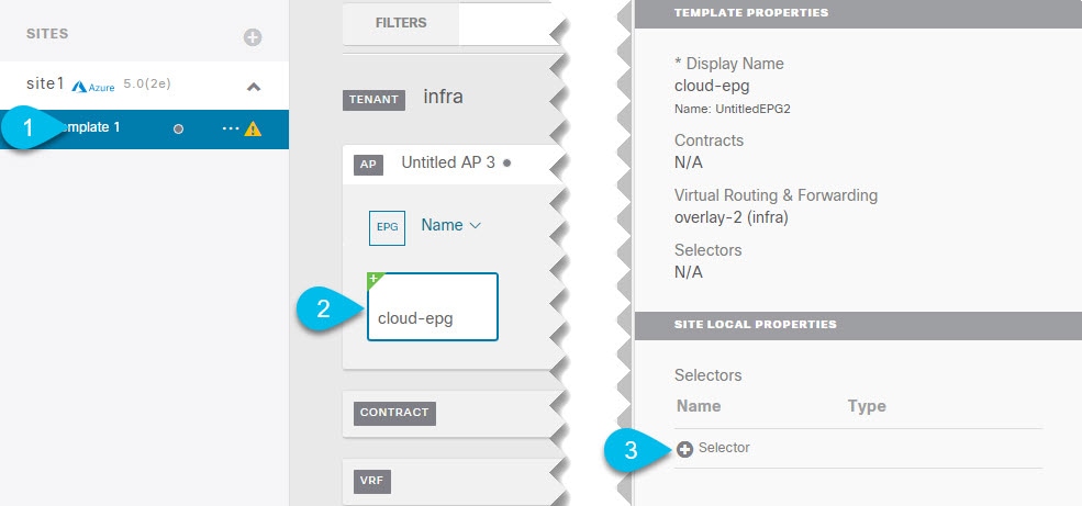 |
| Step 2 |
Define the endpoint selector rules. 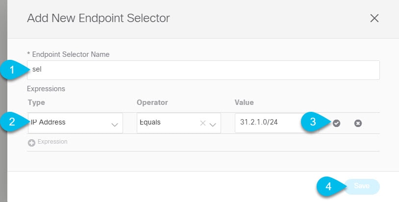 |
Creating Service Graphs
This section describes how to configure one or more devices for a service graph and deploy it to an Azure cloud site.
Procedure
|
Add one or more Service Graph nodes. 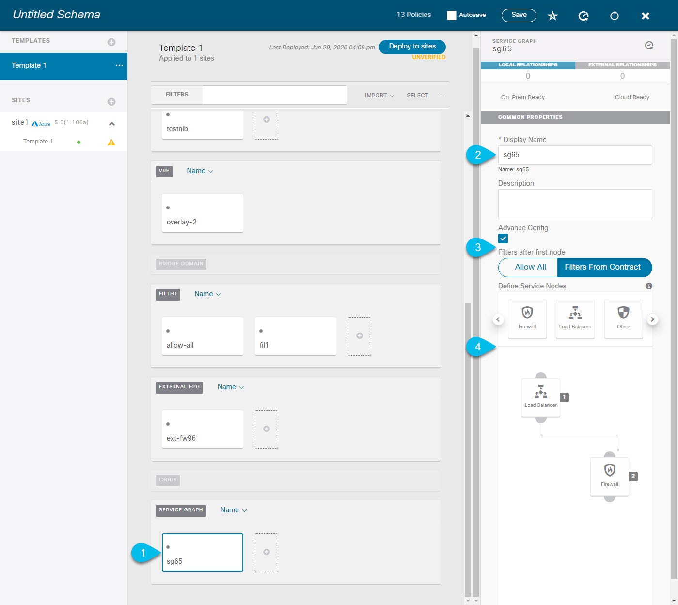 |
What to do next
Configuring Service Graph's Site-Local Properties
This section describes how to configure the service graph devices in an Azure cloud site.
Before you begin
-
You must have created a service graph as described in Creating Service Graphs.
Procedure
| Step 1 |
Navigate to the service graph's site-local properties and select the first node. 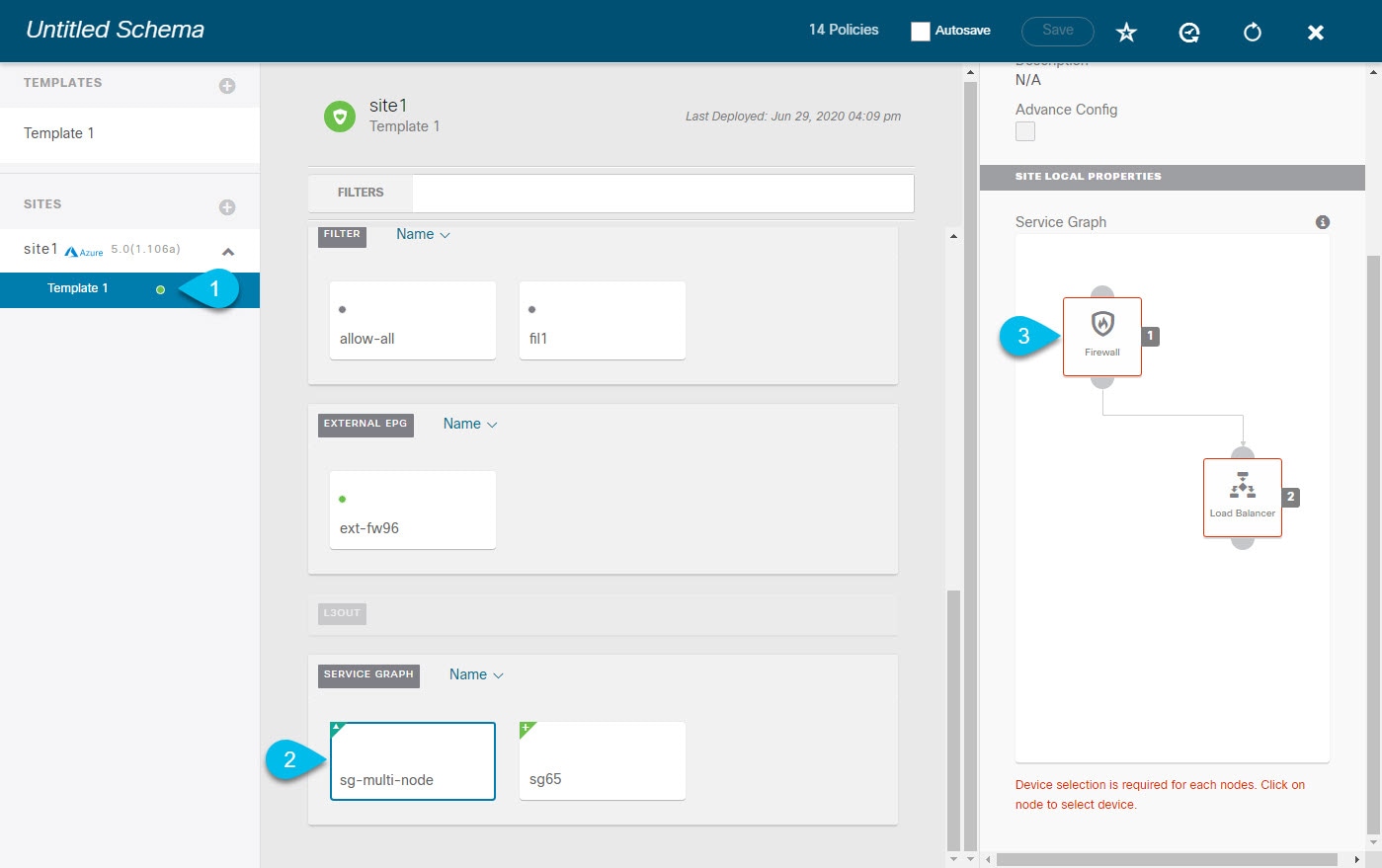 |
||
| Step 2 |
Choose a load balancer device for the service graph node. If you are not adding a load balancer device, skip this step. Beginning with Cisco Cloud APIC Release 5.1(2), you can create a third party load balancer as a service device.
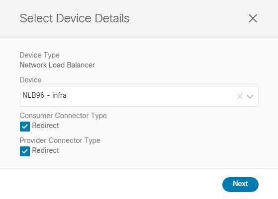
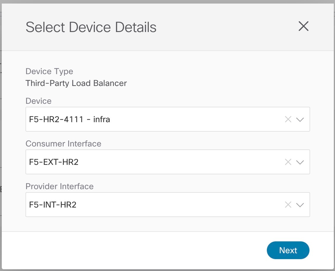
|
||
| Step 3 |
Choose a firewall device for the service graph node. If you are not adding a firewall device, skip this step. 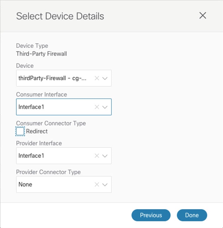 |
Assigning Contract to Service Graph
This section describes how to associate a service graph with a contract.
Before you begin
-
You must have created a contract as described in Creating Filter and Contract.
-
You must have created a service graph as described in Creating Service Graphs.
Procedure
| Step 1 |
In the main pane, select the contract you created. |
| Step 2 |
From the Service Graph dropdown in the right sidebar, select the service graph you created. |
Configuring Listeners for Load Balancer Devices
This section describes how to add a listener to an ALB or NLB node of a service graph.
Listeners enable you to specify the ports and protocols that the load balancer accepts and forwards traffic on. All listeners require you to configure at least one rule (a default rule, which does not have a condition). Rules enable you to specify the action that the load balancer takes when a condition is met. Unlike application gateway, here a rule can only forward traffic to specific port of the backend pool. NLB should be in a separate subnet similar to ALB.
Before you begin
-
You must have created a contract.
-
You must have created a service graph as described in Creating Service Graphs.
-
You must have assigned the service graph to the contract.
Procedure
| Step 1 |
Navigate to the contract's site—local properties and select the first service graph node.  |
| Step 2 |
In the Add Listeners for Load Balancer window, click Add Listener. |
| Step 3 |
Configure a listener for an ALB device. If you are not configuring any ALB devices, skip this step. 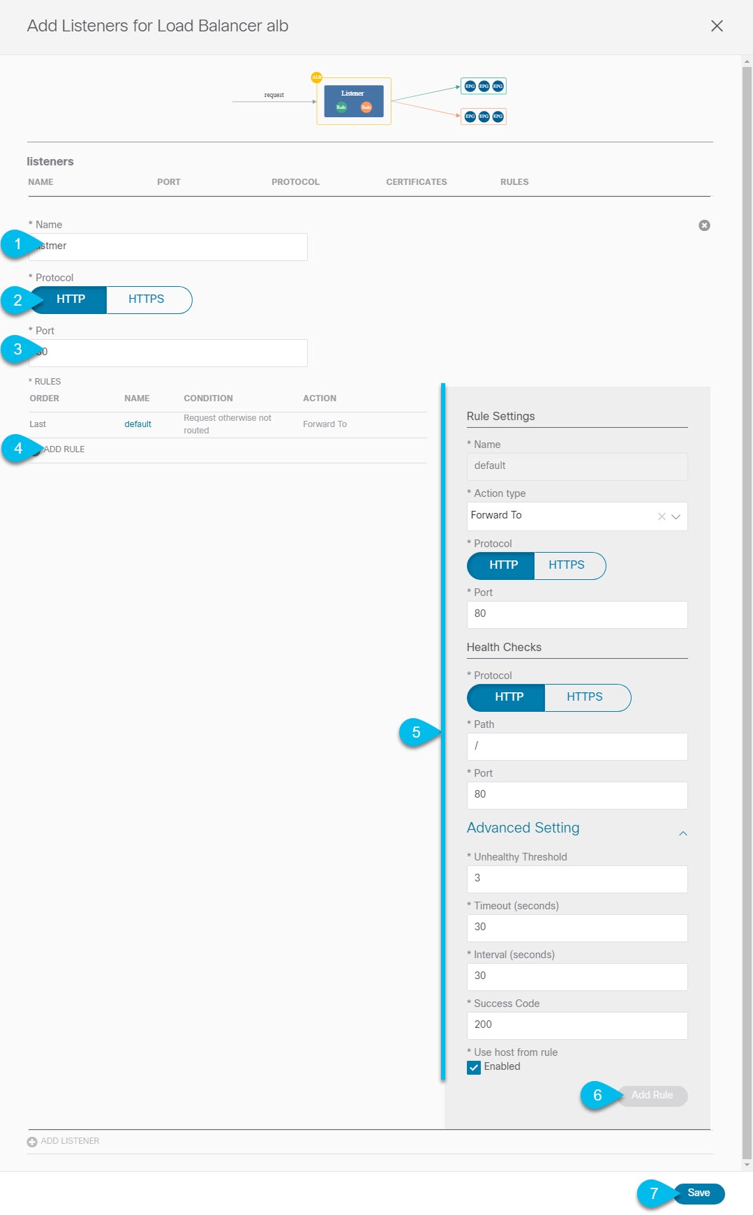 |
| Step 4 |
Configure a listener for an NLB device. If you are not configuring any NLB devices, skip this step. 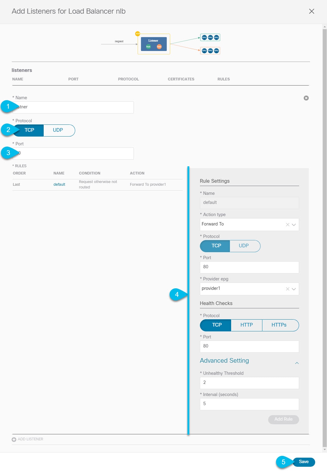 |
 Feedback