Routed Connectivity to External Networks

This chapter contains the following sections:

About Routed Connectivity to Outside Networks

A Layer 3 outside network configuration (L3Out) defines how traffic is forwarded outside of the fabric. Layer 3 is used to discover the addresses of other nodes, select routes, select quality of service, and forward the traffic that is entering, exiting, and transiting the fabric.


Note


For guidelines and cautions for configuring and maintaining Layer 3 outside connections, see Guidelines for Routed Connectivity to Outside Networks.


For information about the types of L3Outs, see External Layer 3 Outside Connection Types.

Create L3Out Wizard

A new Create L3Out wizard is introduced in APIC release 4.2(1) that provides a straightforward walk-through for configuring an L3Out.

The Create L3Out wizard streamlines the process for configuring an L3Out, which defines how the ACI fabric connects to external layer 3 networks. With the Create L3Out wizard, you make the necessary basic configurations for the L3Out components in the following pages:

  • Identity page: This page is used to configure the basic settings for the L3Out, as well as the static routing and dynamic routing protocols settings.

  • Nodes and Interfaces page: This page is used to configure the node profiles and interface profiles for the Layer 3 and Layer 2 interface types.

  • Protocols page: This page is used to configure specific polices based on the protocols that you selected in the Identity page.

  • External EPG page: This page is used to configure the contract and subnets for the external EPG.

MP-BGP Route Reflectors

Configuring an MP-BGP Route Reflector Using the GUI

Procedure


Step 1

On the menu bar, choose System > System Settings.

Step 2

In the Navigation pane, right-click BGP Route Reflector, and click Create Route Reflector Node.

Step 3

In the Create Route Reflector Node dialog box, from the Spine Node drop-down list, choose the appropriate spine node. Click Submit.

Note


Repeat the above steps to add additional spine nodes as required.

The spine switch is marked as the route reflector node.

Step 4

In the BGP Route Reflector properties area, in the Autonomous System Number field, choose the appropriate number. Click Submit.

Note


The autonomous system number must match the leaf connected router configuration if Border Gateway Protocol (BGP) is configured on the router. If you are using routes learned using static or Open Shortest Path First (OSPF), the autonomous system number value can be any valid value.

Step 5

On the menu bar, choose Fabric > Fabric Policies > Pods > Policy Groups.

Step 6

In the Navigation pane, expand and right-click Policy Groups, and click Create Pod Policy Group.

Step 7

In the Create Pod Policy Group dialog box, in the Name field, enter the name of a pod policy group.

Step 8

In the BGP Route Reflector Policy drop-down list, choose the appropriate policy (default). Click Submit.

The BGP route reflector policy is associated with the route reflector pod policy group, and the BGP process is enabled on the leaf switches.

Step 9

On the menu bar, choose Fabric > Fabric Policies > Profiles > Pod Profile default > default.

Step 10

In the Work pane, from the Fabric Policy Group drop-down list, choose the pod policy that was created earlier. Click Submit.

The pod policy group is now applied to the fabric policy group.

Verifying the MP-BGP Route Reflector Configuration

Procedure


Step 1

Verify the configuration by performing the following actions:

  1. Use secure shell (SSH) to log in as an administrator to each leaf switch as required.

  2. Enter the show processes | grep bgp command to verify the state is S.

    If the state is NR (not running), the configuration was not successful.

Step 2

Verify that the autonomous system number is configured in the spine switches by performing the following actions:

  1. Use the SSH to log in as an administrator to each spine switch as required.

  2. Execute the following commands from the shell window

    Example:

    cd /mit/sys/bgp/inst

    Example:

    grep asn summary
The configured autonomous system number must be displayed. If the autonomous system number value displays as 0, the configuration was not successful.

Layer 3 Out for Routed Connectivity to External Networks

Routed connectivity to external networks is enabled by associating a fabric access (infraInfra) external routed domain (l3extDomP) with a tenant Layer 3 external instance profile (l3extInstP or external EPG) of a Layer 3 external outside network (l3extOut), in the hierarchy in the following diagram:

Figure 1. Policy Model for Layer 3 External Connections

A Layer 3 external outside network (l3extOut object) includes the routing protocol options (BGP, OSPF, or EIGRP or supported combinations) and the switch-specific and interface-specific configurations. While the l3extOut contains the routing protocol (for example, OSPF with its related Virtual Routing and Forwarding (VRF) and area ID), the Layer 3 external interface profile contains the necessary OSPF interface details. Both are needed to enable OSPF.

The l3extInstP EPG exposes the external network to tenant EPGs through a contract. For example, a tenant EPG that contains a group of web servers could communicate through a contract with the l3extInstP EPG according to the network configuration contained in the l3extOut. The outside network configuration can easily be reused for multiple nodes by associating the nodes with the L3 external node profile. Multiple nodes that use the same profile can be configured for fail-over or load balancing. Also, a node can be added to multiple l3extOuts resulting in VRFs that are associated with the l3extOuts also being deployed on that node. For scalability information, refer to the current Verified Scalability Guide for Cisco ACI.

Advertise Host Routes

Enabling Advertise Host Routes on the BD, individual host-routes (/32 and /128 prefixes) are advertised from the Border-Leaf switches (BL). The BD must be associated to the L3out or an explicit prefix list matching the host routes. The host routes must be configured to advertise host routes out of the fabric.

Border-Leaf switches along with the subnet advertise the individual end-point(EP) prefixes. The route information is advertised only if the host is connected to the local POD. If the EP is moved away from the local POD or once the EP is removed from EP database (even if the EP is attached to a remote leaf), the route advertisement is then withdrawn.

Advertise Host Route configuration guidelines and limitations are:

  • When host routes are advertised, the VRF Transit Route Tag is set in order to prevent them from being advertised back into the fabric and installed. In order for this loop protection to work properly, external routers must preserve this route-tag if advertising to another L3Out.

  • If a bridge domain is tied to an EPG that has the same subnet configured for internal leaking, you must also enable the "Advertised Externally" flag on the EPG subnet.

  • The Advertise Host Routes feature is supported on Generation 2 switches or later (Cisco Nexus N9K switches with "EX", "FX", or "FX2" on the end of the switch model name or later; for example, N9K-93108TC-EX).

  • Host route advertisement supports both BD to L3out Association and the explicit route map configurations. We recommend using explicit route map configuration which allows you greater control in selecting individual or a range of host routes to configure.

  • EPs/Host routes in SITE-1 will not be advertised out through Border Leafs in other SITEs.

  • When EPs is aged out or removed from the database, Host routes are withdrawn from the Border Leaf.

  • When EP is moved across SITEs or PODs, Host routes should be withdrawn from first SITE/POD and advertised in new POD/SITE.

  • EPs learned on a specific BD, under any of the BD subnets are advertised from the L3out on the border leaf in the same POD.

  • EPs are advertised out as Host Routes only in the local POD through the Border Leaf.

  • Host routes are not advertised out from one POD to another POD.

  • In the case of Remote Leaf, if EPs are locally learned in the Remote Leaf, they are then advertised only through a L3out deployed in Remote Leaf switches in same POD.

  • EPs/Host routes in a Remote Leaf are not advertised out through Border Leaf switches in main POD or another POD.

  • EPs/Host routes in the main POD are not advertised through L3out in Remote Leaf switches of same POD or another POD.

  • The BD subnet must have the Advertise Externally option enabled.

  • The BD must be associated to an L3out or the L3out must have explicit route-map configured matching BD subnets.

  • There must be a contract between the EPG in the specified BD and the External EPG for the L3out.


    Note


    If there is no contract between the BD/EPG and the External EPG the BD subnet and host routes will not be installed on the border leaf.


  • Advertise Host Route is supported for shared services. For example: epg1/BD1 deployed is in VRF-1 and L3out in another VRF-2. By providing shared contract between EPG and L3out host routes are pulled from one VRF-1 to another VRF-2.

  • When Advertise Host Route is enabled on BD custom tag cannot be set on BD Subnet using route-map.

  • When Advertise Host Route is enabled on a BD and the BD is associated with an L3Out, BD subnet is marked public. If there's a rogue EP present under the BD, that EP is advertised out on L3Out.

Guidelines for Routed Connectivity to Outside Networks

Use the following guidelines when creating and maintaining Layer 3 outside connections.

Topic

Caution or Guideline

Floating SVIs

When running ESXi on UCS B Series blade switches behind a fabric interconnect, we recommend that you leave "Fabric Failover" disabled and allow the DVS running on ESXi itself to achieve redundancy in the event of a failure. If enabled, the LLDP/CDP packets that Cisco ACI uses for deployment will be seen on the active and standby virtual switch ports (vEths), which could cause constant flapping and deployment issues.

Issue where a border leaf switch in a vPC pair forwards a BGP packet with an incorrect VNID to an on-peer learned endpoint

If the following conditions exist in your configuration:

  • Two leaf switches are part of a vPC pair

  • For the two leaf switches connected behind the L3Out, the destination endpoint is connected to the second (peer) border leaf switch, and the endpoint is on-peer learned on that leaf switch

If the endpoint is on-peer learned on the ingress leaf switch that receives a BGP packet that is destined to the on-peer learned endpoint, an issue might arise where the transit BGP connection fails to establish between the first layer 3 switch behind the L3Out and the on-peer learned endpoint on the second leaf switch in the vPC pair. This might happen in this situation because the transit BGP packet with port 179 is forwarded incorrectly using the bridge domain VNID instead of the VRF VNID.

To resolve this issue, move the endpoint to any other non-peer leaf switch in the fabric so that it is not learned on the leaf switch.

Border leaf switches and GIR (maintenance) mode

If a border leaf switch has a static route and is placed in Graceful Insertion and Removal (GIR) mode, or maintenance mode, the route from the border leaf switch might not be removed from the routing table of switches in the ACI fabric, which causes routing issues.

To work around this issue, either:

  • Configure the same static route with the same administrative distance on the other border leaf switch, or

  • Use IP SLA or BFD for track reachability to the next hop of the static route

L3Out aggregate stats do not support egress drop counters

When accessing the Select Stats window through Tenants > tenant_name > Networking > L3Outs > L3Out_name > Stats, you will see that L3Out aggregate stats do not support egress drop counters. This is because there is currently no hardware table in the ASICs that record egress drops from the EPG VLAN, so stats do not populate these counters. There are only ingress drops for the EPG VLAN.

Updates through CLI

For Layer 3 external networks created through the API or GUI and updated through the CLI, protocols need to be enabled globally on the external network through the API or GUI, and the node profile for all the participating nodes needs to be added through the API or GUI before doing any further updates through the CLI.

Loopbacks for Layer 3 networks on same node

When configuring two Layer 3 external networks on the same node, the loopbacks need to be configured separately for both Layer 3 networks.

Ingress-based policy enforcement

Starting with Cisco APIC release 1.2(1), ingress-based policy enforcement enables defining policy enforcement for Layer 3 Outside (L3Out) traffic for both egress and ingress directions. The default is ingress. During an upgrade to release 1.2(1) or higher, existing L3Out configurations are set to egress so that the behavior is consistent with the existing configuration. You do not need any special upgrade sequence. After the upgrade, you change the global property value to ingress. When it has been changed, the system reprograms the rules and prefix entries. Rules are removed from the egress leaf and installed on the ingress leaf, if not already present. If not already configured, an Actrl prefix entry is installed on the ingress leaf. Direct server return (DSR), and attribute EPGs require ingress based policy enforcement. vzAny and taboo contracts ignore ingress based policy enforcement. Transit rules are applied at ingress.

Bridge Domains with L3Outs

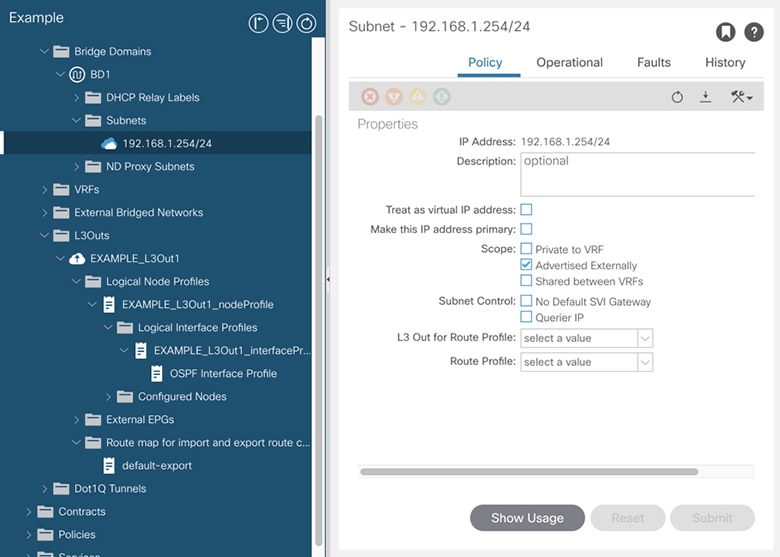
A bridge domain in a tenant can contain a public subnet that is advertised through an l3extOut provisioned in the common tenant.

Bridge domain route advertisement For OSPF and EIGRP

When both OSPF and EIGRP are enabled on the same VRF on a node and if the bridge domain subnets are advertised out of one of the L3Outs, it will also get advertised out of the protocol enabled on the other L3Out.

For OSPF and EIGRP, the bridge domain route advertisement is per VRF and not per L3Out. The same behavior is expected when multiple OSPF L3Outs (for multiple areas) are enabled on the same VRF and node. In this case, the bridge domain route will be advertised out of all the areas, if it is enabled on one of them.

BGP Maximum Prefix Limit

Starting with Cisco APIC release 1.2(1x), tenant policies for BGP l3extOut connections can be configured with a maximum prefix limit, that enables monitoring and restricting the number of route prefixes received from a peer. Once the maximum prefix limit has been exceeded, a log entry is recorded, and further prefixes are rejected. The connection can be restarted if the count drops below the threshold in a fixed interval, or the connection is shut down. Only one option can be used at a time. The default setting is a limit of 20,000 prefixes, after which new prefixes are rejected. When the reject option is deployed, BGP accepts one more prefix beyond the configured limit, before the APIC raises a fault.

MTU

  • Cisco ACI does not support IP fragmentation. Therefore, when you configure Layer 3 Outside (L3Out) connections to external routers, or Multi-Pod connections through an Inter-Pod Network (IPN), it is recommended that the interface MTU is set appropriately on both ends of a link. On some platforms, such as Cisco ACI, Cisco NX-OS, and Cisco IOS, the configurable MTU value does not take into account the Ethernet headers (matching IP MTU, and excluding the 14-18 Ethernet header size), while other platforms, such as IOS-XR, include the Ethernet header in the configured MTU value. A configured value of 9000 results in a max IP packet size of 9000 bytes in Cisco ACI, Cisco NX-OS, and Cisco IOS, but results in a max IP packet size of 8986 bytes for an IOS-XR untagged interface.

  • The MTU settings for the Cisco ACI physical interfaces vary:

    • For sub-interfaces, the physical interface MTU is fixed and is set to 9216 for the front panel ports on the leaf switches.

    • For SVI, the physical interface MTU is set based on the fabric MTU policy. For example, if the fabric MTU policy is set to 9000, then the physical interface for the SVI is set to 9000.

QoS for L3Outs

To configure QoS policies for an L3Out and enable the policies to be enforced on the BL switch where the L3Out is located, use the following guidelines:

  • The VRF Policy Control Enforcement Direction must be set toEgress.

  • The VRF Policy Control Enforcement Preference must be set to Enabled.

  • When configuring the contract that controls communication between the EPGs using the L3Out, include the QoS class or Target DSCP in the contract or subject of the contract.

ICMP settings

ICMP redirect and ICMP unreachable are disabled by default in Cisco ACI to protect the switch CPU from generating these packets.

Example L3Out Configuration

There are many different options available to you when configuring an L3Out using the Create L3Out wizard. Following is one example L3Out configuration, where you will configure an OSPF L3Out with two external routers, that will help you to understand the general configuration process.


Note


This example uses Cisco APIC release 4.2(x) and the associated GUI screens.


Example Topology

Figure 2. Example Topology for an OSPF L3Out with Two External Routers

This basic L3Out example shows you how to:

  • Configure an L3Out with the following specifications:

    • With Area 0 OSPF

    • With two external routers

    • With routed interfaces

    • On two border leaf switches

  • Advertise a BD subnet using default route-map (default-export)

  • Allow communication with a contract between EPG1 and external route (10.0.0.0/8)

Figure 3. OSPF Configuration Diagram

The preceding diagram illustrates the configuration for the example topology in Example Topology for an OSPF L3Out with Two External Routers. The configuration flow for this example is as follows:

  1. L3Out: This creates

    • L3Out itself (OSPF parameters)

    • Node, Interface, OSPF I/F Profiles

    • L3Out EPG with External Subnets for the External EPG scope

  2. Advertise a BD subnet: This uses

    • default-export route-map

    • BD subnet with Advertise Externally scope

  3. Allow EPG - L3Out communication: This uses a contract between EPG1 and L3Out EPG1

Prerequisites

Figure 4. Example Screen of Objects Created as Prerequisites
  • This configuration example focuses only on the L3Out configuration part. The other configurations such as for VRF, BD, EPG, Application Profiles, and Access Policies (Layer 3 Domain etc.) are not covered. The preceding screenshot displays the prerequisite tenant configurations that are as follows:

    • VRF1

    • BD1 with the subnet 192.168.1.254/24

    • EPG1 with a static port towards endpoints

Create Example L3Out Using the Create L3Out Wizard

This task creates the OSPF L3Out described in Example Topology. Following this task, Cisco ACI will be configured with two border leaf switches and OSPF neighborship with two external routers as shown in Example Topology for an OSPF L3Out with Two External Routers.

Procedure


Step 1

In the GUI Navigation pane, under the Tenant Example, navigate to Networking > L3Outs.

Step 2

Right-click and choose Create L3Out.

Step 3

In the Create L3Out screen, Identity tab, perform the following actions:

  1. In the Name field, enter the name for an L3Out. (EXAMPLE_L3Out1)

  2. In the VRF field and the L3 Domain field, choose the appropriate values. (VRF1, EXAMPLE_L3DOM)

  3. In the OSPF field, check the checkbox.

  4. In the OSPF Area ID field, choose the value 0 or the text backbone.

  5. In the OSPF Area Type field, choose Regular area.

  6. Keep the rest of the fields with their default values.

Step 4

Click Next to display the Nodes and Interfaces screen, and perform the following actions:

  1. In the Interface Types area, in the Layer 3 field and in the Layer 2 field, ensure that your selections match the choices in the preceding screenshot (Routed and Port).

  2. In the Nodes area, in the Node ID field, from the drop-down list, choose the appropriate node ID. (leaf2 (Node 102))

  3. In the Router ID field, enter the appropriate router ID. (2.2.2.2)

    The Loopback Address field auto populates based on the router ID value you enter. You do not require the loopback address, so delete the value and leave the field blank.

  4. In the Interface field, choose the interface ID. (eth1/11)

  5. In the IP Address field, enter the associated IP address. (172.16.1.1/30)

  6. In the MTU field, keep the default value. (inherit)

  7. Click the + icon next to the MTU field to add an additional interface for node leaf2. (Node-102)

  8. In the Interface field, choose the interface ID. (eth1/12)

  9. In the IP Address field, enter the associated IP address. (172.16.2.1/30)

  10. In the MTU field, keep the default value. (inherit)

Step 5

To add another node, click the + icon next to the Loopback Address field, and perform the following actions:

Note


When you click the + icon, the new Nodes area is displayed below the area that you had populated earlier.

  1. In the Nodes area, in the Node ID field, from the drop-down list, choose the node ID. (leaf3 (Node-103))

  2. In the Router ID field, enter the router ID. (3.3.3.3)

    The Loopback Address field auto populates based on the router ID value you enter. You do not require the loopback address, so delete the value and leave the field blank.

  3. In the Interface field, choose the interface ID. (eth1/11)

  4. In the IP Address field, enter the IP address. (172.16.3.1/30)

  5. In the MTU field, keep the default value. (inherit)

  6. Click the + icon next to the MTU field to add an additional interface for node leaf3. (Node-103)

  7. In the Interface field, choose the interface ID. (eth1/12)

  8. In the IP Address field, enter the associated IP address. (172.16.4.1/30)

  9. In the MTU field, keep the default value. (inherit), and click Next.

    We have specified the node, interface, and IP address for each interface.

Step 6

Click Next to view the Protocols screen.

This screen allows you to specify the OSPF interface level policy to configure hello-interval, network-type, etc.

In this example, nothing is selected. Therefore, the default policy is used. The default OSPF interface profile uses Unspecified as network-type which defaults to broadcast network type. To optimize this with point-to-point network-type for sub-interface, see Change the OSPF Interface Level Parameters (Optional).

Step 7

Click Next.

The External EPG screen is displayed with L3Out EPG details. This configuration is to classify the traffic into the EPG to apply to the contract.

Step 8

In the External EPG screen, perform the following actions:

  1. In the External EPG area, Name field, enter a name for the external EPG. (L3Out_EPG1)

  2. In the Provided Contract field, do not choose a value.

    In this example, there is no provided contract for L3Out_EPG1 because a normal EPG (EPG1) is the provider.

  3. In the Consumed Contract field, choose default from the drop-down list.

Step 9

In the Default EPG for all external networks field, uncheck the checkbox, and perform the following actions:

  1. Click the + icon in the Subnets area, to display the Create Subnet dialog box.

  2. In the IP Address field, enter the subnet. (10.0.0.0/8)

  3. In the External EPG Classification field, check the checkbox for External Subnets for the External EPG. Click OK.

Step 10

Click the + icon in the Subnets area once more to display the Create Subnet dialog box, and perform the following actions:

Note


Although this is an optional configuration, it is a best practice to specify the L3Out interface subnets in case endpoints have to communicate with those IPs.

  1. In the IP Address field, enter the subnet. (172.16.0.0/21)

    This subnet covers all the interfaces in the L3Out. This can be each individual subnet for each routed interface instead.

  2. In the External EPG Classification field, check the checkbox for External Subnets for the External EPG. Click OK.

  3. Click Finish.


The L3Out OSPF is now deployed.

Review - Create Example L3Out Using the Create L3Out Wizard

Review how the configuration using the wizard is presented in the Cisco APIC GUI, and verify that the configurations are accurate.

Procedure


Step 1

Navigate to your Tenant_name > Networking > L3Outs > EXAMPLE_L3Out1, in the Work pane, scroll to view the details as follows:

At this location in the GUI, verify the main L3Out parameters such as VRF, domain, and OSPF parameters that are configured in the Identity screen in the Create L3Out wizard.

Step 2

Verify that OSPF is enabled with the specified parameters such as Area ID and Area Type.

Step 3

Under Logical Node Profiles, EXAMPLE_L3Out1_nodeProfile is created to specify border leaf switches with their router IDs.

Step 4

Under Logical Interface Profile, EXAMPLE_L3Out1_interfaceProfile is created.

Verify the interface parameters such as interface ID, IP addresses, in this example, as routed interfaces. The default MAC addresses gets auto populated. OSPF interface profile is also created under this for OSPF interface level parameters.


The review is complete.

Configure Advertise the BD Subnet with a Route Map

In this example, a route map, default-export, is used with the IP prefix list to advertise the BD subnet.


Note


This default-export route map will be applied to the L3Out (EXAMPLE_L3Out1) without being associated to anything specific.


Procedure


Step 1

To enable a BD subnet to be advertised, navigate to Tenant > Networks > Bridge Domains > BD1 > Subnets > 192.168.1.254/24, and select Advertised Externally scope.

Step 2

To create a route map under your L3Out (EXAMPLE_L3Out1), navigate to Route map for import and export route control.

Step 3

Right-click and choose Create Route map for import and export route control.

Step 4

In the Create Route map for import and export route control dialog box, in the Name field, choose default-export.

Step 5

In the Type field, choose Matching Route Policy Only.

Note


Match Routing Policy Only: By choosing this Type with default-export route map, all route advertisement configuration is performed by this route map. BD associations and export route control subnets configured under the external EPG will not apply. You should configure all match rules within this route-map for all routes that will be advertised from this L3Out.

Match Prefix and Routing Policy: By choosing this Type with default-export route map, route advertisement is matched by any match rules configured in this route map in addition to any BD to L3Out associations and export route control subnets defined under the External EPG.

When using a route profile, it is recommended to use Match Routing Policy Only for a simpler configuration that is easier to maintain.

Step 6

In the Contexts area, click the + icon, to display the Create Route Control Context dialog box, and perform the following actions:

  1. In the Order field, configure the order. (0)

    In this example, we have only one order.

  2. In the Name field, enter a name for the context. (BD_Subnets)

  3. In the Action field, choose Permit.

    This enables the route map to permit the prefix we will configure.

In this example, we require the match rule that requires the IP prefix list, BD1_prefix. This IP prefix list points to the BD subnet advertised.

Step 7

In the Match Rule field, create the IP prefix-list by performing the following actions;

  1. Choose Create Match Rule for a Route-Map.

  2. In the Name field, enter a name BD1_prefix.

  3. In the Match Prefix area, click the + icon, and enter the BD subnet (192.168.1.0/24).


Verify the Contract

In this task, you verify the contract to enable communication between an endpoint (192.168.1.1) and external prefixes (10.0.0.0/8, and optionally 172.16.0.0/21). In this example, the EPG for the endpoint is EPG1 and the external EPG for external prefixes is L3Out_EPG1.

The required configuration should already be present from the Create L3Out wizard.

Procedure


Step 1

Under your L3Out, navigate to External EPGs > L3Out_EPG1.

Step 2

In the Work pane, in the External EPG Instance Profile area, under Policy > General sub-tab, look at the Properties and verify that the two subnets are displayed with External Subnets for the External EPG.

Step 3

Next, click the Contracts sub-tab and verify the contract you specified earlier is consumed correctly. In case you want to add more contracts, you can perform the actions from this location in GUI.

Step 4

Navigate to Application Profile > Application EPGs > EPG1 > Contracts, and verify that EPG1 is providing the appropriate contract.


Change the OSPF Interface Level Parameters (Optional)

If you wish to change the OSPF interface-level parameters, such as Hello Interval, OSPF network type, then you can configure it in the OSPF Interface Profile. The node level OSPF parameters are already configured.

Procedure


Step 1

Under your L3Out, navigate to Logical Interface Profile > EXAMPLE_L3Out1_interfaceProfile > OSPF Interface Profile.

Step 2

In the Work pane, in the Properties area, choose the OSPF Interface Policy you wish to use.


This modifies your OSPF interface level parameters.