Cisco ACI with Cisco AVS

This chapter includes the following sections:

Cisco AVS Overview

The Cisco Application Virtual Switch (AVS) is a key part of the Cisco Application Centric Infrastructure (ACI). It is a distributed virtual switch that offers different forwarding and encapsulation options and extends across many virtualized hosts and data centers defined by the VMware vCenter Server.

The Cisco AVS is integrated with the Cisco ACI architecture as a virtual leaf and is managed by the Cisco APIC. The Cisco AVS implements the OpFlex protocol for control plane communication.

This section provides an overview of the Cisco AVS.

The Cisco AVS supports two modes of traffic forwarding: Local Switching mode, formerly known as Fex disable mode; and No Local Switching mode, formerly known as Fex enable mode. You choose the forwarding mode during Cisco AVS installation.

Local Switching Mode

In Local Switching mode, all intra-EPG traffic is locally forwarded by the Cisco AVS, without the involvement of the leaf. All inter-EPG traffic is forwarded through the leaf. In this mode, the Cisco AVS can use either VLAN or VXLAN encapsulation—or both—for forwarding traffic to the leaf and back. You choose the encapsulation type during Cisco AVS installation.

Beginning with Cisco AVS Release 5.2(1)SV3(2.5), you can configure a single VMM domain in Local Switching mode to use VLAN and VXLAN encapsulation. Previously, encapsulation was determined solely by the presence of VLAN or multicast pools, and you needed to have separate VMM domains for EPGs using VLAN and VXLAN encapsulation.

If you choose VLAN encapsulation, a range of VLANs must be available for use by the Cisco AVS. These VLANs have local scope in that they have significance only within the Layer 2 network between the Cisco AVS and the leaf. If you choose VXLAN encapsulation, only the infra-VLAN needs to be available between the Cisco AVS and the leaf. This results in a simplified configuration and is the recommended encapsulation type if there are one or more switches between the Cisco AVS and the physical leaf.
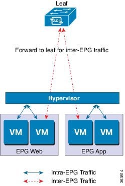
Figure 1. The Cisco AVS in Local Switching Mode

Illustration of the Cisco AVS in local switching mode

No Local Switching Mode

In No Local Switching mode, all traffic is forwarded by the leaf. In this mode, VXLAN is the only allowed encapsulation type.
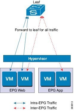
Figure 2. The Cisco AVS in No Local Switching Mode


Statistics Collection

Statistics collection is enabled on Cisco AVS by default. You may see Cisco AVS faults within the APIC GUI relating to VM resource use.

You should troubleshoot those faults in the VMware vCenter because the Cisco ACI only generates these faults based on information it receives from VMware vCenter.

About the Cisco AVS and the VMware vCenter

The Cisco Application Virtual Switch (AVS) is a distributed virtual switch that extends across many virtualized hosts. It manages a data center defined by the vCenter Server.

The Cisco AVS is compatible with any upstream physical access layer switch that complies with the Ethernet standard, including Cisco Nexus switches. The Cisco AVS is compatible with any server hardware listed in the VMware Hardware Compatibility List (HCL).

The Cisco AVS is a distributed virtual switch solution that is fully integrated within the VMware virtual infrastructure, including VMware vCenter for the virtualization administrator. This solution allows the network administrator to configure virtual switch and port groups in order to establish a consistent data center network policy.

The following figure shows a topology that includes the Cisco AVS with the Cisco Application Policy Infrastructure Controller (APIC) and VMware vCenter.
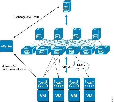
Figure 3. Sample Cisco AVS Topology


Note

If there are multiple vCenters connected to a single Cisco ACI fabric, you should ensure that there are no overlapping MAC address allocation schema across the multiple vCenters while deploying the vCenters instead of the default OUI allocation. Overlaps can cause duplicate MAC address generation. For more information, see VMware documentation.

Cisco AVS in a Multipod Environment

The Cisco AVS can be part of a multipod environment. Multipod environments use a single APIC cluster for all the pods; all the pods act as a single fabric.

Multipod environments enable a more fault tolerant fabric comprising multiple pods with isolated control plane protocols. They also provide greater flexibility in full mesh cabling between leaf and spine switches.

Cisco AVS does not require any additional configuration to operate in a multipod environment.

For detailed information about multipod environments, see the following documents on Cisco.com:

  • Cisco Application Centric Infrastructure Fundamentals

  • Cisco APIC Getting Started Guide

  • Cisco APIC NX-OS Style Command-Line Interface Configuration Guide

The following features are not supported for Cisco AVS with multipod in the Cisco APIC 2.0(1.x) release:

  • L3 Multicast

  • Storage vMotion with two separate NFS in two separate PODs

  • ERSPAN destination in different PODs

  • Distributed Firewall syslog server in different PODs

Required Software

The following table shows the versions of software you need to install for Cisco Application Virtual Switch (AVS) to work with the Cisco Application Policy Infrastructure Controller (APIC), VMware vCenter, and VMware ESXi hypervisor:

Component

Description

Cisco AVS software

Cisco AVS is supported in Release 4.2(1)SV2(2.3) and later releases. However, Release 5.2(1)SV3(1.5) or later is required if you want to use Distributed Firewall and Microsegmentation with Cisco AVS.

Cisco APIC

See the Cisco AVS Release Notes for compatibility information. However, version 1.1(1j) or later is required with Cisco AVS 5.2(1)SV3(1.5) or later if you want to use Distributed Firewall and Microsegmentation with Cisco AVS.

VMware vCenter

Cisco AVS is compatible with release 5.5, 6.0, or 6.5 of VMware vCenter Server.

VMware vSphere bare metal

Cisco AVS is supported as a vLeaf for the Cisco APIC with release 5.5 and later releases of the VMware ESXi hypervisor.

Note 
When you choose a Cisco AVS VIB, you need to choose the one compatible with the version of VMware ESXi hypervisor that you use. ESXi 5.5 uses xxix.3.2.1.vib, ESXi 6.0 uses xxxx.6.0.1.vib, and ESXi 6.5 uses xxxx.6.5.1.vib.

Cisco Virtual Switch Update Manager (VSUM)

Cisco AVS is supported in VSUM Release 1.0 and later releases.

Cisco AVS Documentation

You can find documentation on the Cisco Application Virtual Switch page on Cisco.com.

Documentation for Cisco Application Virtual Switch (AVS) includes:
  • Cisco Application Virtual Switch Release Notes

  • Cisco Application Virtual Switch Documentation Overview

  • Cisco Application Virtual Switch Installation Guide

  • Cisco Application Virtual Switch Download Instructions for VMware ESXi Deployments

  • Cisco Application Virtual Switch Configuration Guide

  • Cisco Application Virtual Switch Verified Scalability Guide

  • Cisco Application Virtual Switch Solution Guide

  • Cisco Application Virtual Switch Troubleshooting Guide

  • Cisco Virtual Switch Update Manager Getting Started Guide

  • Cisco Virtual Switch Update Manager Release Notes

  • Cisco Virtual Switch Update Manager Troubleshooting Guide
Cisco AVS Installation

Installing the Cisco Application Virtual Switch (AVS) consists of two separate sets of tasks: configuring the Cisco Application Policy Infrastructure Controller (APIC) and then installing Cisco AVS using the Cisco Virtual Switch Update Manager (VSUM), the ESXi CLI, or the VMware Virtual Update Manager (VUM). You also must verify the installation.

This section provides the instructions for each set of tasks that you need to perform to install Cisco AVS to use within the Cisco Application Centric Infrastructure (ACI) fabric.

Workflow for Installing the Cisco AVS

This section provides a high-level description of the tasks that you need to perform in order to install the Cisco AVS.

  1. Create interface and switch policies and a VMware vCenter domain profile for the Cisco AVS in the unified configuration wizard in the Cisco Application Policy Infrastructure Controller (APIC) GUI.

    An interface policy configures the type of interface—port channel (PC) or virtual PC (VPC)—for the vSphere hosts and a link aggregation control protocol (LACP), or MAC pinning. See the appendix "Recommended Topologies" in the Cisco Application Virtual Switch Installation Guide for supported topologies.

    A switch policy configures the connection between the Cisco AVS (the vLeaf) and the ESXi hypervisor by specifying a physical port on the leaf switch and by specifying Cisco AVS trunk settings. These include VLANs or VXLANs.

    A VMware vCenter domain groups virtual machine (VM) controllers with similar networking policy requirements. For example, VM controllers can share VLAN or Virtual Extensible Local Area Network (VXLAN) space and application endpoint groups (EPGs). The Cisco APIC communicates with the controller to publish network configurations such as port groups that are then applied to the virtual workloads.

    See the section "Creating Interface and Switch Policies and a vCenter Domain Profile Using the GUI" in this guide for instructions.
  2. Install the Cisco AVS and add the ESXi host to the Cisco AVS.


    Note

    You can connect a single ESX or ESXi host to only one Cisco AVS at a time. You cannot add multiple Cisco AVS to a single ESX or ESXi host.

    Using Cisco VSUM is the recommended method for installing the Cisco AVS. Using Cisco VSUM validates the version and compatibility for the ESXi host, and in one procedure enables you to install the Cisco AVS onto the ESXi host and add the ESXi host to the Cisco AVS distributed virtual switch (DVS).

    See the section "Completing the Cisco AVS Installation with Cisco VSUM" in this guide for instructions for installing the Cisco AVS using VSUM.

    However, you can install Cisco AVS using the VMware vCenter plug-in. You should use the vCenter plug-in to install Cisco AVS only if you are already using it to perform other tasks or if you plan to do so. See Installing Cisco AVS Using the VMware vCenter Plug-in in this guide.

    You also can install Cisco AVS using the ESXi CLI or VMware Virtual Update Manager (VUM). You might want to do so if you have one or few Cisco AVS. See Installing the Cisco AVS Software Using the ESXi CLI in this guide or "Installing the Cisco AVS Software Using VMware VUM" in the Cisco Application Virtual Switch Installation Guide for instructions.

  3. Verify the Cisco AVS Installation.

    You need to verify that the Cisco AVS has been installed on the VMware ESXi hypervisor by verifying the virtual switch status and the virtual NIC status. You also need to verify that the vmknic is created, that OpFlex is online, and that the ports are in a forwarding state.

    See the section Verifying the Cisco AVS Installation in this guide for instructions.

  4. Add hosts to the Cisco AVS.

    Once you have installed the Cisco AVS, you can add hosts, one at a time, to it.

    See the section Adding Cisco AVS Hosts to the DVS in this guide for instructions.

Creating Interface, Switch, and vCenter Domain Profiles

Before you can install the Cisco AVS, you need to create interface, switch, and vCenter domain profiles. As of Cisco APIC 1.1.x, we recommend that you perform these tasks in the united configuration wizard in the Cisco APIC. This is the procedure "Creating Interface and Switch Profiles and a vCenter Domain Profile Using the Advanced GUI" in this guide.

You should understand and follow the guidelines in this section before proceeding with the tasks.

Alternate Procedures

If you need to configure a FEX profile or detailed interface, switch, or vCenter domain profiles, you can find instructions in Appendix C, "Procedures for Creating Interface, Switch, and vCenter Domain Profiles" in the Cisco Application Virtual Switch Installation Guide.

Firewall Considerations

If you use the recommended united configuration wizard, the Cisco APIC automatically creates a firewall policy, which can be modified later. If you instead use the alternate procedures to create interface, switch, or vCenter domain profiles, you will need to create a firewall policy manually. Follow the instructions in the Distributed Firewall section of this guide.

Interface and Switch Profile Guidelines and Prerequisites

Follow these guidelines and fulfil the prerequisites when creating interface and switch profiles for your Cisco AVS.

Guidelines for Creating Interface and Switch Profiles

The Cisco AVS supports PC, VPC, MAC Pinning, and FEX interface policies. It does not support individual interface policies. See the Cisco Application Virtual Switch Installation Guide for information about FEX policies.

  • If there is a Layer 2 network between the leaf switch and the Cisco AVS vSphere host, configure the interface policy on the interfaces that are connected to the Layer 2 network.

  • The number of links and leafs that you use determine whether you need to configure a PC or a VPC policy for the Cisco AVS:

    • If you are using a single link between a leaf and an ESXi host, you need to configure a PC policy.

    • If you are using multiple links between one leaf and an ESXi host, you must configure a PC policy.

    • If you are using multiple links between multiple leafs and an ESXi host, you must configure a VPC policy.

  • Follow these guidelines for choosing a LACP policy:

    • Choose LACP (Active or Passive) if the uplinks from the Cisco AVS (vSphere host) are directly connected to the leaf switches and you want to use or turn on the LACP channeling protocol.

    • Choose Static Channel - Mode On if the uplinks form the Cisco AVS are directly connected to the leaf switches but you do not want to use the LACP channeling protocol, for example, static port channel.

    • Choose MAC Pinning if the uplinks from the Cisco AVS should not be channeled together and will operate as separate links.

Prerequisites for Creating Interface and Switch Profiles

You should verify that the leaf switch interfaces are physically connected to the ESXi hypervisor or, if you are using a Layer 2 device, verify that the leaf is physically connected to the Layer 2 device.

vCenter Domain Profile Guidelines and Prerequisites

You must create a new vCenter domain profile; you cannot convert an existing one. For information about deleting an existing VMware vCenter domain profile, see the section "Guidelines for Deleting VMM Domains" in Cisco Application Centric Infrastructure Fundamentals.

Guidelines for Creating a VMware vCenter Domain Profile

You can create multiple data centers and DVS entries under a single domain. However, you can have only one Cisco AVS assigned to each data center.

If you choose VXLAN encapsulation and MAC pinning link aggregation, we recommend that you enable VXLAN load balancing. See the section “Enabling VXLAN load balancing” in the Cisco Application Virtual Switch Configuration Guide.


Note

VXLAN load balancing is enabled by default. However, to use it effectively, you need to configure additional VMK NICs to match the number of PNICs.

Beginning with Cisco AVS Release 5.2(1)SV3(1.15), you can use IPv6 when creating a VMM domain, provided that the vCenter and ESXi host management are IPv6-enabled.

Prerequisites for Creating a VMware vCenter Domain Profile

Make sure that the multicast IP address pool has enough multicast IP addresses to accommodate the number of EPGs that will be published to the VMware vCenter domain. You can add more IP addresses to a multicast address pool that is already associated with a VMware vCenter domain at any time.

Make sure that you have a sufficient number of VLAN IDs. If you do not, ports on endpoint groups (EPGs) might report that no encapsulation is available.

If you want to change the switch mode on a Cisco AVS, you first must remove the existing DVS and then add the VMware vCenter domain with the desired switching mode. For instructions on removing the existing DVS, see Cisco Application Virtual Switch Configuration Guide.

vCenter must be installed, configured, and reachable through the in-band/out-of-band management network.

You must have the administrator/root credentials to the vCenter.


Note

If you prefer not to use the vCenter administrator/root credentials, you can create a custom user account with minimum required permissions. See Custom User Account with Minimum VMware vCenter Privileges for a list of the required user privileges.

Creating Interface and Switch Profiles and a vCenter Domain Profile Using the GUI


Note

If you want to choose a delimiter for the VMware PortGroup name when you create a vCenter domain, you cannot do so in this procedure, which uses the configuration wizard. Instead, you must create the vCenter domain separately; the delimiter option appears in the Create vCenter Domain dialog box. See the procedure "Creating a VMware vCenter Domain Profile" in the Cisco Application Virtual Switch Installation Guide.


Before you begin

Before you create a vCenter domain profile, you must establish connectivity to external network using in-band management network on the Cisco APIC.

Procedure

Step 1

Log into the Cisco APIC.

Step 2

On the menu bar, click Fabric > Access Policies.

Step 3

In the Policies navigation pane, click Quick Start, and then in the central pane click Configure an interface, PC, and VPC.

Step 4

In the Configure Interfaces, PC, and VPC dialog box, expand Configured Switch Interfaces, click the green + icon, and then perform the following steps:

  1. In the Select Switches to Configure Interfaces area, make sure that the Quick radio button is selected.

  2. From the Switches drop-down list, choose the appropriate leaf ID.

    In the Switch Profile Name field, the switch profile name automatically appears.

  3. Click the green + icon again.

    The Configure Interfaces, PC, and VPC dialog box displays a wizard that enables you to configure interface, switch, and vCenter domain profiles.

Step 5

In the wizard, perform the following actions:

  1. In the Interface Type area, choose the appropriate radio button.

    PC or VPC are the only valid options for Cisco AVS deployment. See the section Guidelines for Creating Interface and Switch Policies in this guide.

  2. In the Interfaces field, enter the interface or interface range for your vSphere hosts.

    Once you enter the interface or interface range, the wizard enters a name in the Interface Selector Name field.

  3. In the Interface Policy Group area, choose the Create One radio button.

    Note 
    This procedure assumes that you are creating interface and switch policies and creating a vCenter domain from scratch. If you choose the Choose One radio button, you will not be able to do so in the wizard.
  4. From the CDP Policy or the LLDP Policy drop-down list, create a policy.

    Note 
    If you use a Cisco Unified Computing System (UCS) server, create a policy to enable a Cisco Discovery Protocol (CDP) policy and a policy to disable Link Layer Discovery Protocol (LLDP).
    Note 
    Beginning with Cisco AVS Release 5.2(1)SV3(1.15), CDP and LLDP policies are disabled by default. You must enable them in the configuration wizard. Enable CDP or LLDP policies in the Interface Policy Group area to enable them on Cisco AVS and other switches in the fabric. If you want to enable CDP or LLDP only on Cisco AVS, enable them in the vSwitch Policy area of the configuration wizard.
  5. From the Link Level Policy drop-down list, choose the desired link level policy or create one.

    The link level policy specifies the speed of the physical interface. If you do not choose a link level policy, the speed will default to 10 Gbps.
  6. In the Port Channel Policy drop-down list, choose Create Port Channel Policy.

    You need to choose the same policy that is on the ESXi server. For example, if the server does not support LACP, you can choose Static Channel - Mode On or MAC Pinning.

  7. In the Attached Device Type area, choose AVS VLAN Hosts or AVS VXLAN Hosts.

    Note 
    If the hypervisors are directly connected to leaf switches, you can use either VLAN or VXLAN. (Cisco UCS blade servers, where Fabric Interconnects are connected to the fabric, are considered to be directly connected.) However, if the hypervisors are not directly connected to leaf switches, you must use VXLAN. For more information, see the Overview section.
  8. In the Domain area, make sure that the Create One radio button is chosen.

    The Create One option is used when creating a new VMM domain for an interface or switch profile, as you do in this procedure. The Choose One button is used when creating an interface or switch profile for a new host that you want to make part of an existing VMM domain.

  9. In the Domain Name field, enter the domain name.

    Note 
    When you create the VMM domain, you choose VLAN or VXLAN encapsulation, depending on the attached device type you chose in Step 5g. However, beginning with Cisco AVS Release 5.2(1)SV3(2.5), you can configure a single VMM domain to use VLAN and VXLAN encapsulation. After you finish installing the Cisco AVS, you can enable mixed encapsulation mode. See the section "Mixed-Mode Encapsulation Configuration" in the Cisco Application Virtual Switch Configuration Guide.
  10. If you chose AVS VLAN Hosts in Step 5 g, in the VLAN Range field, enter the VLAN range as appropriate.

    Note 
    Do not define a range that includes the reserved VLAN ID for infrastructure network because that VLAN is for internal use.
  11. If you chose AVS VXLAN Hosts in Step 5 g, in the Fabric Multicast Address field, enter an address, such as 225.1.1.1.

  12. If you chose AVS VXLAN Hosts in Step 5 g, in the Pool of Multicast Address Ranges field, create a new multicast pool or choose an existing one.

    Note 
    The multicast address configured in Step 5 l must not overlap with the ranges configured in Step 5 m.
  13. If you chose AVS VXLAN Hosts in Step 5 g, in the Local Switching area, choose True or False.

    With local switching, traffic within an endpoint group (EPG) does not go to the leaf, so if you choose local switching, you might not see some traffic counters. If you want to see all intra-EPG traffic, you should choose False. See the section Cisco Application Virtual Switch Overview for additional information about Local Switching and No Local Switching modes.
  14. (Optional) From the Security Domains drop-down list, choose or create a security domain.

  15. In the vCenter Login Name field, enter the vCenter Administrator/root username.

  16. In the Password field, enter the vCenter Administrator/root password.

  17. In the Confirm Password field, reenter the password.

Step 6

Click the + icon to expand vCenter, and in the Create vCenter Controller dialog box, perform the following actions:

  1. In the Name field, enter a name to refer to the vCenter domain.

    The name does not need to be the same as the vCenter domain name; you can use the vCenter host name.

  2. In the Host Name (or IP Address) field, enter the host name or IP address.

    If you use the host name, you must already have configured a DNS policy on Cisco APIC. If you do not have a DNS policy configured, enter the IP address of the vCenter server.

  3. From the DVS Version drop-down list, choose a DVS version.

    The DVS version that you choose represents the minimum ESXi version of the host that can be added to the virtual switch. So if you choose DVS version 5.5, you can add or manage hosts of ESXI version 5.5 and later.

  4. In the Datacenter field, enter the data center name.

    Note 
    The name that you enter for Datacenter must match exactly the name in vCenter. The name is case sensitive.
  5. Click OK.

    Note 
    For the following three steps, if you do not specify port channel, vSwitch, or interface control policies, the same interface policy that you configured earlier in this procedure will take effect for the vSwitch.
  6. From the Port Channel Mode drop-down list, choose a mode.

    Choose MAC Pinning if you have a Unified Computing System (UCS) Fabric Interconnect (FI) between the top-of-rack switch and the Cisco AVS.

  7. In the vSwitch Policy area, choose a policy.

  8. In the Interface Controls area, choose BPDU Guard, BPDU Filter, or both.

  9. From the Firewall drop-down list, choose Learning, Enabled or Disabled mode.

    Learning mode, the default, should be used only when upgrading from a version of Cisco AVS that does not support Distributed Firewall to a version that does. Otherwise, Distributed Firewall should be in Enabled mode.You can change the Distributed Firewall mode later. See the section Creating a Distributed Firewall Policy or Changing its Mode Using the GUI in this guide for instructions.
Step 7

In the Configure Interface, PC, And VPC dialog box, click SAVE, click SAVE again, and then click SUBMIT.

Step 8

Verify the new domain and profiles, by performing the following actions:

  1. On the menu bar, choose Virtual Networking > Inventory.

  2. In the navigation pane, expand VMM Domains > VMware > Domain_name > Controllers, and then choose the vCenter.

In the work pane, under Properties, view the virtual machine manager (VMM) domain name to verify that the controller is online. In the work pane, the vCenter properties are displayed including the operational status. The displayed information confirms that connection from the APIC controller to the vCenter server is established, and the inventory is available.

Configuring vSwitch Override Policies on the VMM Domain Using the GUI

Before installing Cisco AVS, you can use the configuration wizard to create a VMware vCenter profile and create interface policy group policies for Cisco AVS. You also can create vSwitch policies that override the interface policy group policies and apply a different policy for the leaf.

However, if you did not use the configuration wizard—or if you used the configuration wizard but did not configure a vSwitch override policy—you can configure a vSwitch override policy by following the procedure in this section.


Note

In Cisco AVS 5.2(1)SV3(1.10), you cannot create a Distributed Firewall policy on the vSwitch using the configuration wizard. See the section "Configuring Distributed Firewall" in this guide for instructions for configuring a Distributed Firewall policy and associating it to the VMM domain.

Note

Previously, you could configure a vSwitch override policy through the Fabric tab as well as the Virtual Networking tab. Override policies configured through the Virtual Networking tab took precedence. However, any override policy configured through the Fabric tab stands until it is reconfigured through the Virtual Networking tab.
Before you begin

We recommend that you already have created access policies and an attachable access entity profile for Cisco AVS.

Procedure

Step 1

Log in to the Cisco APIC.

Step 2

Go to Virtual Networking > Inventory > VMM Domains > VMware.

Step 3

In the navigation pane, choose the relevant VMM domain.

Step 4

In the VMM domain work pane, scroll to the VSwitch Policies area, and from the appropriate vSwitch policy drop-down list, choose the policy that you want to apply as an override policy.

Step 5

Click Submit.


What to do next

Verify that the policies are in effect on Cisco AVS.

Pre-Cisco AVS Installation Configuration Using the NX-OS Style CLI

You can perform some pre-Cisco AVS installation configuration tasks using the NX-OS style CLI.

Creating a VLAN Domain Using the NX-OS Style CLI
Procedure

Create a VLAN domain.

Example:
Configuring a VLAN domain with static allocation:
apic1# configure
apic1(config)# vlan-domain cli-vdom1
apic1(config-vlan)# vlan 101-200 

apic1(config-vlan)# show running-config 
# Command: show running-config vlan-domain cli-vdom1 
# Time: Thu Oct  1 10:12:21 2015
  vlan-domain cli-vdom1 
    vlan 101-200 
    exit
Example:
Configuring a VLAN domain with dynamic allocation:
apic1# configure
apic1(config)# vlan-domain cli-vdom1 dynamic
apic1(config-vlan)# vlan 101-200 dynamic

apic1(config-vlan)# show running-config 
# Command: show running-config vlan-domain cli-vdom1 dynamic
# Time: Thu Oct  1 10:12:21 2015
  vlan-domain cli-vdom1 dynamic
    vlan 101-200 dynamic
    exit

Configuring a Port Channel Using the NX-OS Style CLI
Procedure

Create a port channel.

Example:

apic1# config
apic1(config)# template port-channel cli-pc1
apic1(config-if)# channel-mode active
apic1(config-if)# vlan-domain member cli-vdom1

apic1(config-if)# show running-config 
# Command: show running-config interface port-channel cli-pc1
# Time: Thu Oct  1 10:38:30 2015
  interface port-channel cli-pc1
    vlan-domain member cli-vdom1
    channel-mode active
    exit

Configuring a VPC Using the NX-OS Style CLI

Configuring a Virtual Port Channel (VPC) using the NX-OS style CLI consists of two tasks: configuring a VPC domain and then configuring the VPC on the switch interfaces.

Configuring a VPC Domain Using the NX-OS Style CLI
Procedure

Configure a VPC domain.

Example:

apic1# config
apic1(config)# vpc domain explicit 10 leaf 101 102

apic1(config-vpc)# show running-config 
# Command: show running-config vpc domain explicit 10 leaf 101 102
# Time: Thu Oct  1 10:39:26 2015
  vpc domain explicit 10 leaf 101 102
    exit

Configuring a VPC on Switch Interfaces Using NX-OS Style CLI
Procedure

Configuring a VPC on switch interfaces

Example:

apic1# config
apic1(config)# leaf 101 – 102
apic1(config-leaf)# interface ethernet 1/3
apic1(config-leaf-if)# channel-group cli-pc1 vpc

apic1(config-leaf-if)# show running-config 
# Command: show running-config leaf 101 - 102 interface ethernet 1/3
# Time: Thu Oct  1 10:41:15 2015
  leaf 101
    interface ethernet 1/3
      channel-group cli-pc1 vpc
      exit
    exit
  leaf 102
    interface ethernet 1/3
      channel-group cli-pc1 vpc
      exit
    exit

Creating a VMM Domain with Local Switching or No Local Switching Using the NX-OS Style CLI
Procedure

Create a VMM domain with local switching or no local switching.

Example:
apic1(config)# vmware-domain cli-vmm1 delimiter=@
apic1(config-vmware)# vlan-domain member cli-vdom1
apic1(config-vmware)# vcenter 10.193.218.223 datacenter dc1 dvs-version 5.5
apic1(config-vmware-vc)# username root 
Password: 
Retype password: 
apic1(config-vmware-vc)#
apic1(config-vmware)# configure-avs
apic1(config-vmware-avs)# switching mode vlan
<or>
apic1(config-vmware-avs)# switching mode vxlan-ns
apic1(config-vmware-avs)# multicast-address 226.0.0.1
apic1(config-vmware-avs)# vxlan multicast-pool 226.0.0.11-226.0.0.20

apic1(config-vmware-vc)# show running-config 
# Command: show running-config vmware-domain cli-vmm1 vcenter 10.193.218.223 datacenter dc1 dvs-version 5.5
# Time: Thu Oct  1 10:51:45 2015
  vmware-domain cli-vmm1 delimiter=@
    vcenter 10.193.218.223 datacenter dc1 dvs-version 5.5
      username root
      exit
    exit

apic1(config-vmware-avs)# show running-config 
# Command: show running-config vmware-domain cli-vmm1 configure-avs
# Time: Thu Oct  1 10:53:28 2015
  vmware-domain cli-vmm1 delimiter=@
    configure-avs
      switching mode vlan | vxlan | vxlan-ns
      exit
    exit

In the initial string vmware-domain cli-vmm1 delimiter=@, delimiter=@ is optional. If you do not enter a delimiter, the system will use the default | delimiter.

For switching mode, mode might be vxlan or vxlan-ns. The string vxlan-ns is VXLAN encapsulation with no local switching.

Note 
Beginning in Cisco AVS Release 5.2(1)SV3(2.5), you can configure a single VMM domain to use VLAN and VXLAN encapsulation. You can do so after creating the VMM domain in this procedure by following the procedure "Checking or Changing the VMM Domain Encapsulation Mode" in the Cisco Application Virtual Switch Configuration Guide.

Prerequisites for Installing Cisco AVS

Installing Cisco AVS has the following prerequisites:

  • You must set up the Cisco APIC before you can set up the Cisco AVS. See the Cisco APIC Getting Started Guide for instructions on how to configure the Cisco APIC for the first time.

  • You must make sure that all switches are registered and that the Cisco ACI fabric is up to date. See Cisco Application Centric Infrastructure Fundamentals and the Cisco APIC Getting Started Guide.

  • The Cisco AVS configuration in the Cisco APIC must be completed manually. See the section Creation of Interface and Switch Policies and the vCenter Domain Profile in this guide or the Cisco Application Virtual Switch Installation Guide for detailed information about configuring the Cisco APIC before Cisco AVS installation.

  • If you want to use Cisco VSUM to install the Cisco AVS, you first must install Cisco VSUM. See the section Installing Cisco VSUM in this guide.

  • If you want to use Cisco VSUM to install the Cisco AVS, you must have downloaded the appropriate Cisco AVS image file from Cisco.com and uploaded it to the Cisco VSUM repository. See the sections About the Virtual Switch Image File Upload Utility and Uploading the Cisco AVS Image File in this guide.

  • You have created a tenant configuration that contains the required bridge domain, application profile, endpoint groups, and contracts. See the Cisco APIC Getting Started Guide for more information.

  • The host has one or more unclaimed physical NICs.

  • You have administrative privileges for the vCenter Server.

  • When connecting the Cisco AVS using VXLAN encapsulation, set the maximum transmission unit (MTU) value equal to or greater than 1600 on all intermediate devices on the path between the Cisco ACI fabric and the Cisco AVS. These include FI switches and UCS-B. However, to optimize performance, the MTU should be set to the maximum supported size that all intermediate devices on the path between the Cisco ACI fabric and the Cisco AVS support.

  • When adding additional VMware ESXi hosts to the VMM domain for the Cisco AVS, ensure that the version of the ESXi host is compatible with the Distributed Virtual Switch (DVS) version already deployed in the vCenter. For more information about Cisco AVS compatibility for ESXi hosts, see the Cisco AVS Release Notes for your Cisco AVS release.

    If the ESXi host version is not compatible with the existing DVS version, vCenter will not be able to add the ESXi host to the DVS, and an incompatibility error will occur. Modification of the existing DVS Version setting from the Cisco APIC is not possible. To lower the DVS Version in the vCenter, you need to remove and reapply the VMM domain configuration with a lower setting.


Important

If you have ESXi 6.5 hosts running UCS B-Series or C-Series server with VIC cards, some of the vmnics may go down on a port state event, such as a link flap or a TOR reload. To prevent this problem, do not use the default eNIC driver but install it from the VMware website: https://my.vmware.com/web/vmware/details?downloadGroup=DT-ESXI65-CISCO-NENIC-1020&productId=614.

Installing Cisco AVS Using the VMware vCenter Plug-in

You can install Cisco AVS using the Cisco AVS plug-in in VMware vCenter, avoiding the need to install the switch software with Cisco VSUM, VUM, or the CLI.

You should use the vCenter plug-in to install Cisco AVS if you are already using it to perform other tasks or if you plan to do so. We do not recommend using the vCenter plug-in to install Cisco AVS unless you plan to use it for other tasks. For information about the vCenter plug-in, see the chapter Cisco ACI vCenter Plug-in in this guide.

This procedure does the following:

  1. Places the host into maintenance mode.

    If the host cannot be put into maintenance mode, the installation will not start.

  2. Uploads the appropriate VIB file to the host data store.

    The plug-in chooses the appropriate VIB file for east host, based on the version of ESXi host and version of Cisco AVS that you choose.

  3. Installs Cisco AVS software.

  4. Deletes the VIB file from the host data store.

  5. Takes the host out of maintenance mode.

Before you begin

  • You must have downloaded the .zip folder with the VIB file from Cisco.com to your local computer.

  • You must have made sure that it is compatible with the version of Cisco APIC; check the Cisco AVS Release Notes on Cisco.com for compatibility.

  • You must have already created a VMM domain on Cisco APIC.

  • You must have already registered the ACI fabric inside the vCenter plug-in.

    For instructions, see Connecting vCenter Plug-in to your ACI Fabric in this guide.

  • You also must have fulfilled the other prerequisites for installing Cisco AVS documented earlier in this guide.


Note

You cannot use the vCenter plug-in to migrate hosts.

Procedure


Step 1

Log in to VMware vSphere Web Client.

Step 2

Choose Cisco ACI Fabric > Cisco AVS.

Step 3

At the top of the central work pane, from the Select an ACI domain drop-down list, choose a domain.

When you choose a domain, the work pane displays the host or hosts in the vCenter related to the VMM domain. The central pane displays the following columns:
  • Name—Name of the host

  • ESX Version—The ESX or ESXi version on the host

  • Added to Domain—Whether the host is connected to the Cisco AVS associated with the selected domain

  • OpFlex State—Whether the OpFlex agent on the host is online

  • AVS Version—The version of Cisco AVS, if any, installed on the host

Step 4

Choose a one or more hosts by clicking the appropriate check box or check boxes.

Step 5

In the Actions area of the work pane, perform one of the following actions from the AVS version drop-down list:

  • Choose the version of Cisco AVS to be installed on the selected hosts; you see versions in the drop-down list if you previously uploaded a Cisco AVS version to vCenter.
  • Choose Upload a new AVS version to open a dialog box enabling you to upload a new Cisco AVS package from the VIB file on your local computer to vCenter.
Step 6

In the Concurrent Tasks drop-down, if you chose multiple hosts in Step 4, choose how many hosts on which to install Cisco AVS at the same time.

You can choose up to 10 hosts on which to install Cisco AVS at the same time. If you choose multiple hosts but do not choose a number from the Concurrent Tasks drop-down list, the default value of 2 will apply.

Step 7

Choose Install/Upgrade AVS.

Step 8

In the Install AVS dialog box, click Yes to put the hosts into maintenance mode.

In the central work pane, the AVS version for the host displays installation progress. You also can view progress of the individual installation tasks in the Recent Tasks area.

What to do next

Verify the Cisco AVS installation. See Verifying the Cisco AVS Installation in this guide for instructions.


Note

The procedure installs the VIB on the host; however, the host still needs to be manually connected to the switch.

Installing the Cisco AVS Using Cisco VSUM

Once you have finished configuring the Cisco AVS in the Cisco APIC, you complete the installation of the Cisco AVS in the Cisco VSUM. You do so by installing the Cisco AVS and adding the ESXi host to the Cisco AVS.

Installing Cisco VSUM

You can install the Cisco VSUM OVA using the following steps.

Before you begin
  • Ensure that the Cisco VSUM OVA image is available in the file system.

  • Ensure that you have the IP address, subnet mask, gateway IP address, domain name, DNS server, and vCenter IP address and credentials for deploying the OVA.


    Note

    When you install Cisco VSUM, you must use the same credentials that you use to install the thick client.
Procedure

Step 1

Log in to the VMware vSphere Web Client.


Step 2

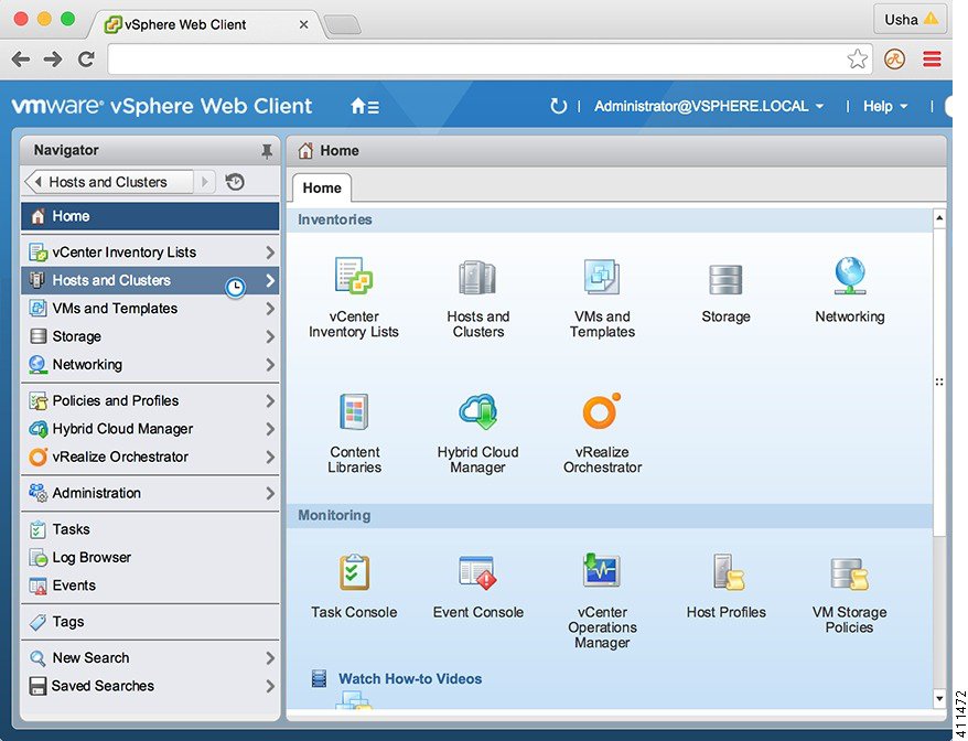
Choose Hosts and Clusters.


Step 3

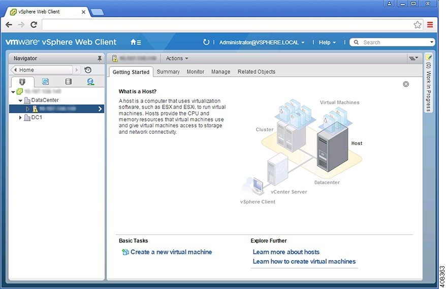
Choose the host on which to deploy the Cisco VSUM OVA.


Step 4

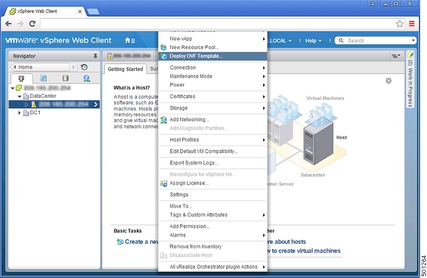
From the Actions menu, choose Deploy OVF Template.

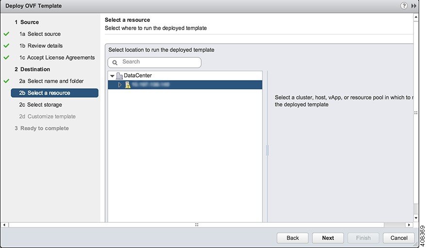
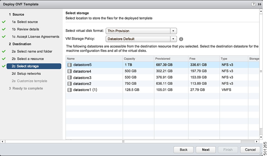
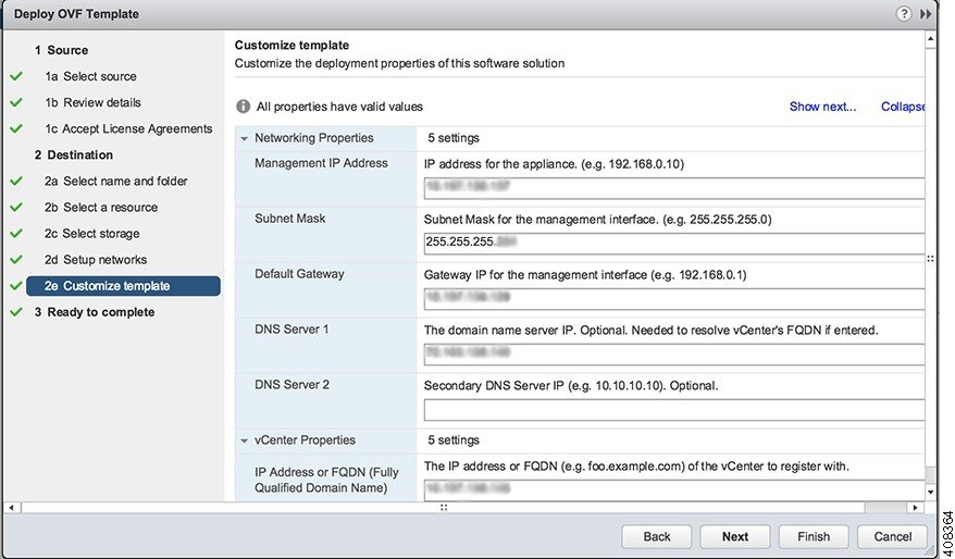
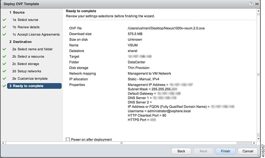
Step 5

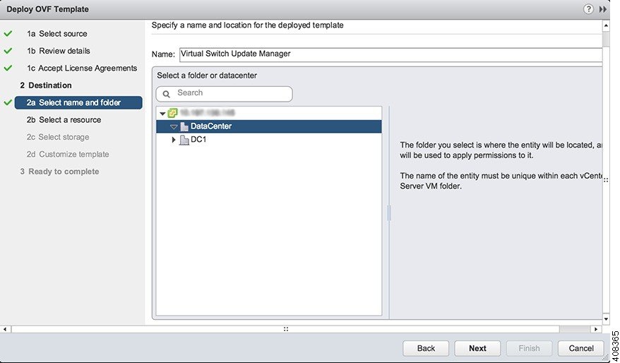
In the Deploy OVF Template wizard, complete the information as described in the following table.

Pane Action

1a Select source

Choose the Cisco VSUM OVA.


1b Review details

Review the details.


1c Accept License Agreements

Review the agreement and click Accept.


2a Select name and folder

Enter a name and choose a location for the appliance.


2b Select a resource

Choose the host or cluster to run the OVA template.


2c Select storage

Choose the data store for the VM.

Choose either Thin provisioned format or Thick provisioned format to store the VM virtual disks.

We recommend that you store the VM virtual disks in the Thick provisioned format.

2d Setup networks

Choose the destination network for the VM that is reachable from the vCenter Server.


2e Customize template

Provide the following information:

  • Management IP address

  • Subnet mask

  • Gateway IP address

  • DNS server IP address

  • DNS entry to resolve the fully qualified domain name (FQDN)

  • vCenter IP or FQDN

  • vCenter username

  • vCenter password

  • HTTP cleartext port and HTTPS port


3 Ready to complete

Review the deployment settings.

Caution 
Any discrepancies can cause VM booting issues. Carefully review the IP address, subnet mask, gateway information, and vCenter credentials.


Step 6

Click Finish.

Step 7

After Cisco VSUM deploys successfully, click Close.

Step 8

Power on the Cisco VSUM VM.

It might take 5 minutes for Cisco VSUM to be installed and registered as a vSphere Web Client plug-in.

If the Web Client session was open during the installation, you must log out and log in again to view the Cisco VSUM plug-in.


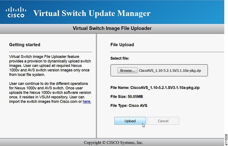
About the Virtual Switch Image File Upload Utility

The Virtual Switch Image File Upload utility is a GUI that enables you to dynamically upload the Cisco AVS image files before you install Cisco AVS. You must download the Cisco AVS image files from Cisco.com on your local system before you upload them to the Cisco VSUM repository.

Uploading the Cisco AVS Image File

Before you install Cisco AVS using Cisco VSUM, you must upload the corresponding Cisco AVS image file to Cisco VSUM.

Before you begin

Download the Cisco AVS .zip image folder from https://software.cisco.com/download.


Attention

You must download the Cisco AVS .zip image folder before starting the upload operation.


Procedure

Step 1

Log in to the VMware vSphere Web Client.

Step 2

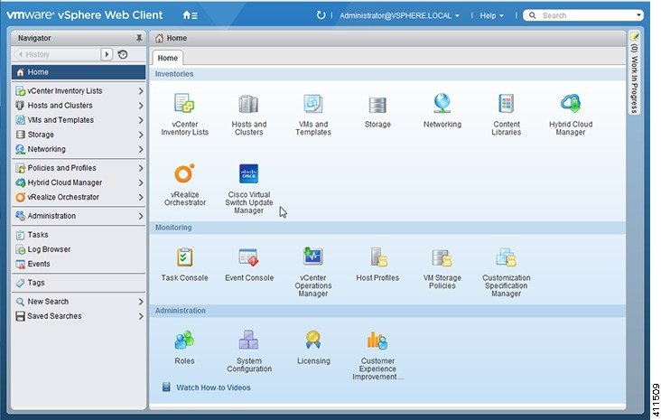
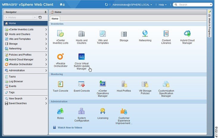
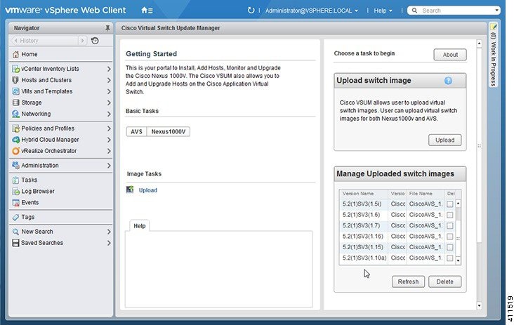
Choose Home > Cisco Virtual Switch Update Manager.


Step 3

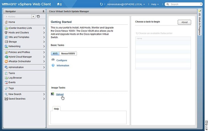
In the Cisco Virtual Switch Update Manager pane, choose AVS > Upload.


Step 4

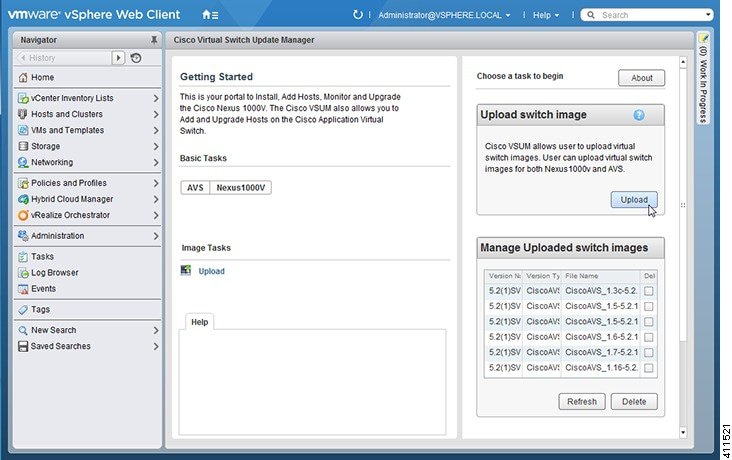
In the Upload Switch Image pane, click Upload.


Step 5

In the Virtual Switch Image File Uploader window, click Browse, choose the appropriate image folder available on your local machine, and then click Upload.


The upload might take a few minutes.

Step 6

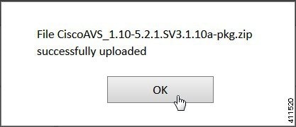
In the dialog box telling you that the .zip image folder was successfully uploaded, click OK.


Step 7

You can confirm the upload in the Manage Uploaded switch Images pane.


What to do next

Install Cisco AVS as described in the remaining procedures in this chapter.

Installing Cisco AVS Using VSUM

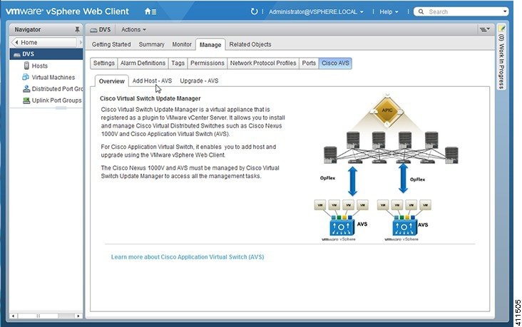
The following procedure—using the feature labeled Add Host-AVS in Cisco VSUM—puts the hosts into maintenance mode, installs the Cisco AVS, and adds an ESXi host or multiple hosts to the Cisco AVS.

Before you begin

You must obtain the following information for the Cisco AVS:

  • vCenter IP address

  • vCenter user ID

  • vCenter password

Procedure

Step 1

Log in to the VMware vSphere Web Client.

Step 2

Choose Home > Cisco Virtual Switch Update Manager.


Step 3

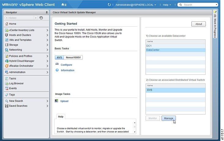
In the Cisco Virtual Switch Update Manager pane, choose AVS > Configure, choose a data center, choose the Cisco AVS, and then click Manage.

You choose the Cisco AVS from the Choose an associated Distributed Virtual Switch area.


Step 4

In the switch pane, choose Cisco AVS > Add Host-AVS.


Step 5

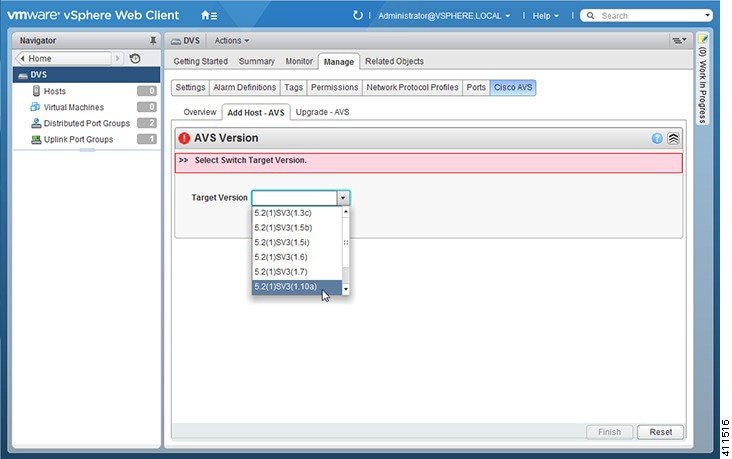
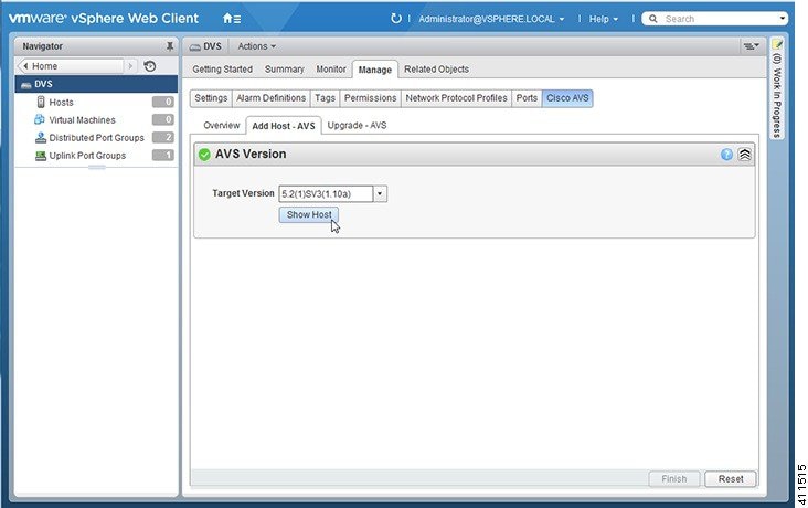
In the Add Host-AVS tab, complete the following actions:

  1. From the Target Version drop-down list, choose the target VIB version to be installed on the host.


  2. Click Show Host.


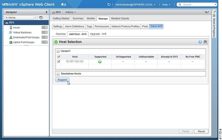
    The hosts are represented in the following categories:

    • Cluster—Hosts that are part of clusters.

    • Standalone—Hosts that are not part of clusters. You can add hosts that are in a standalone mode.

  3. Expand Cluster or Standalone, depending on your setup.

    Hosts are further organized within the Cluster and Standalone categories:

    • Supported—Hosts that are supported by the Cisco AVS. You can add these hosts.

    • Unsupported—Hosts that are not supported by the Cisco AVS.

    • Unreachable—Hosts that are in a not responding state or are in a disconnected state.

    • Already in DVS—Hosts that are already associated with the DVS. You cannot add a host that is already associated with a DVS.

    • No free PNIC—Hosts that do not have a free PNIC. You cannot add a host that does not have a free PNIC.

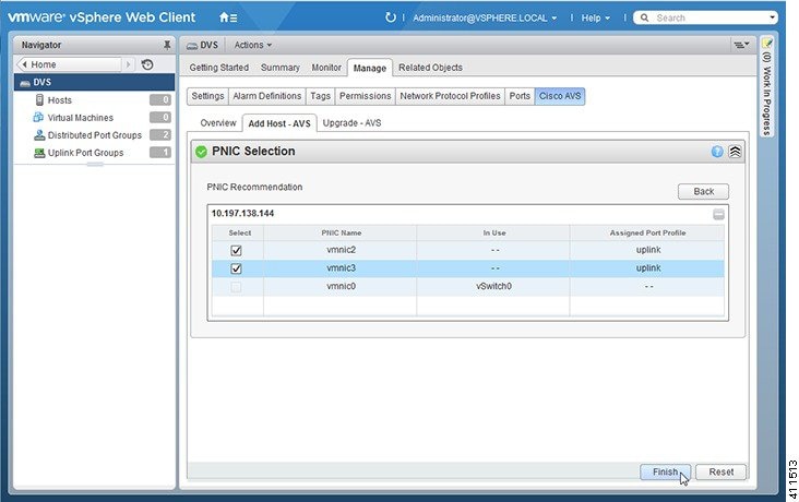
  4. Choose one or more available hosts and then click Suggest.


    The PNIC Selection area displays the available uplinks for each host.
  5. In the PNIC Selection area, choose the PNIC or PNICs to be added to the Cisco AVS.


  6. Click Finish to add the host or hosts to the Cisco AVS.

Step 6

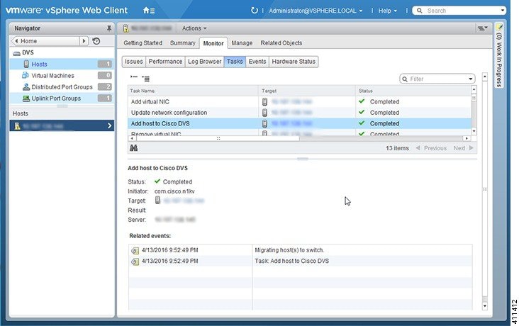
Check the status of adding the host by completing the following steps:

  1. Choose the host in the left navigation pane.

  2. Click the Monitor tab and then click Tasks.


    The task console appears in the work pane, displaying a list of tasks with the most recent task at the top.

  3. Find the task in the Task Name column and then view the status in the Status column.

    The Status column shows whether the task is complete or in progress.

    Note 

    Several tasks might appear above the primary task you just performed. They might be associated with your primary task.

    The host addition is confirmed when the primary task Add hosts to Cisco DVS has the status Completed.

If you close the browser and later want to view the task's history, log in to the VMware vSphere Web Client, and click Tasks in the navigation pane to display the lists of tasks in the work pane.


What to do next

Verify the Cisco AVS installation. See Verifying the Cisco AVS Installation in this guide for instructions.

Installing the Cisco AVS Software Using the ESXi CLI

You can install the Cisco AVS on the ESXi hypervisor with the CLI using a vSphere Installation Bundle (VIB).

Procedure


Step 1

Open an ESXi CLI session to the ESXi hypervisor.

Step 2

Download the Cisco AVS VIB file from Cisco.com or the VMware portal.

Step 3

copy scp://filepath/file-name root@host:/tmp

Copy the Cisco AVS VIB to the ESXi hypervisor.

Example:

esxhost# copy scp://username@server/path/cisco-vem-v165-esx.vib root@host:/tmp
Step 4

esxcli software vib list | grep cisco

Locate the VIB on the ESXi hypervisor.

Note 
If there is an existing VIB file on the host, remove it by using the esxcli software remove command.

Example:

esxhost# esxcli software vib list | grep cisco
cisco-vem-v164-esx            5.2.1.2.2.0.88-3.1.74          Cisco     PartnerSupported     2014-03-31
Step 5

esxcli software vib install -v absolute path to the image

Install the VIB on the ESXi hypervisor.

Example:

esxhost# esxcli software vib install -v /tmp/cross_cisco-vem-v165-4.2.1.2.2.2.473-3.1.165.vib
Installation Result
   Message: Operation finished successfully.
   Reboot Required: false
   VIBs Installed: cisco-vem-v164-esx_5.2.1.2.2.0.88-3.1.74
   VIBs Removed: 
   VIBs Skipped: 
esxhost#
Note 
At this point, you might see the following error message:
[InstallationError]
Error in running rm /tardisks/cisco_ve.v00:
Return code: 1
Output: rm: can't remove '/tardisks/cisco_ve.v00': Device or
resource busy
It is not safe to continue. Please reboot the host immediately to
discard the unfinished update.
Please refer to the log file for more details.
This message occurs if the host was already added to the Cisco AVS in the vCenter. The solution is to log in to VMware vSphere Web Client and in the vCenter remove the vmk1 under the distributed switch.
Step 6

vemcmd show version

Displays the VIB version.

Example:

[root@localhost:~] vemcmd show version
VEM Version: 5.2.1.3.3.9.972-6.0.1
OpFlex SDK Version: 3.0(0.257a)
System Version: VMware ESXi 6.0.0 Releasebuild-2494585
ESX Version Update Level: 0
[root@localhost:~]

Verifying the Cisco AVS Installation

The following sections describe how to verify that the Cisco Application Virtual Switch (AVS) has been installed on the VMware ESXi hypervisor.

Verifying the Virtual Switch Status

Procedure

Step 1

Log in to the VMware vSphere Client.

Step 2

Choose Networking.

Step 3

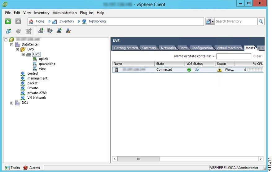
Open the folder for the data center and click the virtual switch.

Step 4

Click the Hosts tab.


The VDS Status and Status fields display the virtual switch status. The VDS status should be Up to indicate that OpFlex communication has been established.

Verifying the vNIC Status

Procedure

Step 1

In VMware vSphere Client, click the Home tab.

Step 2

Choose Hosts and Clusters.

Step 3

Click the host.

Step 4

Click the Configuration tab.

Step 5

In the Hardware panel, choose Networking.

Step 6

In the View field, click the vSphere Distributed Switch button.

Step 7

Click Manage Virtual Adapters. The vmk1 displays as a virtual adapter and lists an IP address.

Step 8

Click the newly created vmk interface to display the vmknic status.

Note 
Allow approximately 20 seconds for the vmk to receive an IP address through DHCP.

Adding Cisco AVS Hosts to the DVS

You can add only one host at a time. You need to perform this procedure once for every host that you want to add.

Note

If you installed the Cisco AVS by using the Cisco VSUM, you do not need to perform this procedure; VSUM adds hosts to the DVS at the same time that it installs the Cisco AVS. However, you do need to perform this procedure if you upgraded Cisco AVS by using the CLI or the VMware VUM.


Before you begin

Before you add vLeafs to the DVS, ensure that you have created a tenant configuration that contains the required bridge domain, application profiles, endpoint groups, and contracts. For more information, see the Cisco APIC Getting Started Guide.

Procedure


Step 1

In vSphere Web Client, choose Home >Inventories > Networking.

Step 2

In the left navigation pane, choose AVS Distributed Switch, and then click the Hosts tab.

Step 3

Right-click anywhere within the work pane and choose Add Host to vSphere Distributed Switch.

Step 4

In the Add Host to vSphere Distributed Switch dialog box, choose the virtual NIC ports that are connected to the leaf switch (vmnic2, vmnic3).

Step 5

Click Next.

Step 6

In the Network Connectivity dialog box, click Next.

Step 7

In the Virtual Machine Networking dialog box, click Next.

Step 8

In the Ready to Complete dialog box, click Finish.

Step 9

Repeat Step 1 through Step 8 for each additional host.


Uninstalling Cisco AVS

You might need to remove Cisco AVS for testing or if you need to remove all configuration from the Cisco ACI fabric, resetting the fabric to its initial state. Follow the high-level steps in this procedure to remove the Cisco AVS.

Procedure


Step 1

Complete the following steps in the VMware vSphere Client:

  1. Remove all VMs from EPG port groups.

  2. Remove all Virtual Tunnel Endpoint (VTEP) VMware kernels (VMKs) from the Cisco AVS hosts.

  3. Remove all hosts from the Cisco AVS.

See the VMware documentation for instructions.

Step 2

Complete the following steps in the Cisco APIC:

  1. Remove all virtual machine management (VMM) domain associations to EPGs to delete port groups.

    This step is optional if you are removing all configuration from the Cisco ACI fabric.

  2. Remove the Cisco AVS VMM domain.


What to do next

If you are uninstalling the Cisco AVS but not removing all configuration from the Cisco ACI fabric, you can remove the VIB software from each host where it was installed. You can do so by completing one of the following tasks:

  • Enter the following vSphere CLI command to remove the VIB software from a host: esxcli software vib remove -n installed_vem_version

  • Complete the procedure in the section "Uninstalling Cisco AVS Using the VMware vCenter Plug-in" in this guide.

Uninstalling Cisco AVS Using the VMware vCenter Plug-in

This procedure removes the Cisco AVS VIB file from the host.

You should use the vCenter plug-in to uninstall Cisco AVS if you are already using it to perform other tasks or if you plan to do so. We do not recommend using the vCenter plug-in to uninstall Cisco AVS unless you plan to use it for other tasks. For information about the vCenter plug-in, see the chapter "Cisco ACI vCenter Plug-in" in the Cisco ACI Virtualization Guide on Cisco.com.

Before you begin

  • You must perform the all steps in the procedure "Uninstalling Cisco AVS" except for the task in the "What to do next" section.

  • You must disconnect Cisco AVS from the VMM domain.

Procedure


Step 1

Log in to VMware vSphere Web Client.

Step 2

Choose Cisco ACI Fabric > Cisco AVS.

Step 3

At the top of the central work pane, from the Select an ACI domain drop-down list, choose a domain.

When you choose a domain, the work pane displays the host or hosts in the vCenter related to the VMM domain. The central pane displays the following columns:
  • Name—Name of the host

  • ESX Version—The ESX or ESXi version on the host

  • Added to Domain—Whether the host is connected to the Cisco AVS associated with the selected domain

  • OpFlex State—Whether the OpFlex agent on the host is online

  • AVS Version—The version of Cisco AVS, if any, installed on the host

Step 4

Choose a one or more hosts by clicking the appropriate check box or check boxes.

Step 5

In the Concurrent Tasks drop-down, if you chose multiple hosts in Step 4, choose how many hosts on which to uninstall Cisco AVS at the same time.

You can choose up to 10 hosts on which to uninstall Cisco AVS at the same time. If you choose multiple hosts but do not choose a number from the Concurrent Tasks drop-down list, Cisco AVS will be uninstalled on the hosts one after another.

Step 6

Click Uninstall AVS.

Step 7

In the Uninstall AVS dialog box, click Yes to put the hosts into maintenance mode.

In the central work pane, the AVS version for the host displays uninstallation progress. You also can view progress of the individual uninstallation tasks in the Recent Tasks area. When the uninstallation is complete, "Not installed" will appear for the host in the central work pane AVS Version column.

What to do next

Take the following optional steps to remove from vCenter the version of Cisco AVS you just uninstalled:

  1. Click Remove uploaded versions.

  2. In the Select the AVS versions you wish to remove from vCenter dialog box, click the appropriate check box and then click OK.

Key Post-Installation Configuration Tasks for the Cisco AVS

After you install the Cisco Application Virtual Switch (AVS), you need to perform some configuration tasks in the Cisco Application Policy Infrastructure Controller (APIC).

Prerequisites for Configuring the Cisco AVS

Before you configure the Cisco Application Virtual Switch (AVS), you need to perform the following tasks:
  1. Install the Cisco AVS as described in the previous sections of this guide.

  2. Understand the concepts presented in the ACI Fundamentals Guide and the APIC Getting Started Guide.

Workflow for Key Post-Installation Configuration Tasks for the Cisco AVS

This section provides a high-level description of the tasks that you need to perform in the correct sequence in order to configure Cisco AVS.

  1. Deploy an application profile.

    1. Create a tenant.

      A tenant is a logical container for application policies that enable an administrator to exercise domain-based access control. Tenants can represent a customer in a service provider setting, an organization or domain in an enterprise setting, or just a convenient grouping of policies.

      The fabric can contain multiple tenants. Tenants can be isolated from one another or can share resources. The primary elements that the tenant contains are filters, contracts, outside networks, bridge domains, contexts, and application profiles that contain endpoint groups (EPGs). Entities in the tenant inherit its policies.

      You must configure a tenant before you can deploy any Layer 4 to Layer 7 services.

      See the section Creating a Tenant, Private Network, and Bridge Domain Using the GUI in this guide for instructions for creating tenants.

    2. Create an application profile.

      An application profile models application requirements. An application profile is a convenient logical container for grouping EPGs.

      Modern applications contain multiple components. For example, an e-commerce application could require a web server, a database server, data located in a storage area network, and access to outside resources that enable financial transactions. The application profile contains as many (or as few) EPGs as necessary that are logically related to providing the capabilities of an application.

      See the section Creating an Application Profile Using the GUI in this guide for instructions for creating an application profile.

    3. Create an endpoint group (EPG)

      Endpoints are devices that are connected to the network directly or indirectly. They have an address (identity), a location, attributes (such as version or patch level), and can be physical or virtual. Endpoint examples include servers, virtual machines, network-attached storage, or clients on the Internet.

      An EPG is a named logical entity that contains a collection of endpoints that have common policy requirements such as security, virtual machine mobility, QoS, or Layer 4 to Layer 7 services. EPGs enable you to manage endpoints as a group rather than having to configure and manage them individually; endpoints in an EPG have the same configuration and changes to EPG configuration are propagated automatically to all the endpoints assigned to it. In vCenter Server, an EPG is represented as a port group.

      See the section Creating EPGs Using the GUI in this guide for instructions for creating EPGs.

    4. Assign port groups to virtual machines (VMs) in vCenter.

      In vCenter Server, an EPG is represented as a port group. The virtual Ethernet (vEth) interfaces are assigned in vCenter Server to an EPG in order to do the following:

      • Define the port configuration by the policy.

      • Apply a single policy across a large number of ports.

      EPGs that are configured as uplinks can be assigned by the server administrator to physical ports (which can be vmnics or PNICs). EPGs that are not configured as uplinks can be assigned to a VM virtual port.

      See the section Assigning Port Groups to VMs in vCenter in this guide for instructions.

    5. Create filters.

      A filter is a managed object that helps enable mixing and matching among EPGs and contracts so as to satisfy various applications or service delivery requirements. It specifies the data protocols to be allowed or denied by a contract—rules for communications between EPGs—that contains the filter.

      See the section Creating a Filter Using the GUI in this guide for instructions.

    6. Create contracts.

      Contracts are policies that enable communications between EPGs. An administrator uses a contract to select the type(s) of traffic that can pass between EPGs, including the protocols and ports allowed. If there is no contract, inter-EPG communication is disabled by default. No contract is required for communication within an EPG; communication within an EPG is always implicitly allowed.

      Contracts govern the communication between EPGs that are labeled providers, consumers, or both. An EPG can both provide and consume the same contract. An EPG can also provide and consume multiple contracts simultaneously.

      See the section Creating a Contract Using the GUI in this guide for instructions.

  2. Verify the application profile.

    You need to perform the following tasks to verify that the application profile has been created.

    1. Verify the application profile on the Cisco APIC.

    2. Verify that the EPGs appear in the vCenter.

    3. Ensure that the VMs can communicate.

    See the section Verifying the Application Profile in this guide for instructions.

  3. Configure an IPv4 or IPv6 address

    To configure an IP address for VMs connected to Cisco AVS, you assign an IPv4 or IPv6 address—or both an IPV4 and IPv6 address—for the VM and then assign a gateway address.

    See the section Configuring an IP Address for VMs Connected to Cisco AVS in this guide for instructions.

  4. Configure an IGMP querier under the infra BD subnet.

    In order for Cisco AVS to forward multi-destination traffic—especially when traffic goes through a blade switch—you should configure an IGMP querier under the infra BD subnet. This enables devices to build their Layer 2 multicast tree.

    See the section "Configuring IGMP Querier and Snooping" in the Cisco AVS Configuration Guide for instructions.

  5. (Optional but recommended) Enable Distributed Firewall.

    After you install or upgrade to Cisco AVS Release 5.2(1)SV3(1.5), you need to enable Distributed Firewall if you want to use the feature. Distributed Firewall is in Learning mode by default. Follow the instructions in Creating a Distributed Firewall Policy or Changing its Mode Using the GUI in this guide to enable Distributed Firewall.

Deploying an Application Profile for Cisco AVS Using the GUI

Basic mode is deprecated after Cisco APIC Release 3.0(1). Cisco does not recommend using Basic mode for configuration. However, if you want to use Basic mode, use the following URL: APIC URL/index.Simple.html

Caution: Cisco recommends that you do not mix configuration modes (Advanced or Basic). When you make a configuration in either mode and change the configuration using the other mode, unintended changes can occur. For example, if you apply an interface policy to two ports using Advanced mode and then change the settings of one port using Basic mode, your changes might be applied to both ports.

Creating a Tenant, VRF, and Bridge Domain Using the GUI

If you have a public subnet when you configure the routed outside, you must associate the bridge domain with the outside configuration.

Procedure

Step 1

On the menu bar, choose Tenants > Add Tenant.

Step 2

In the Create Tenant dialog box, perform the following tasks:

  1. In the Name field, enter a name.

  2. Click the Security Domains + icon to open the Create Security Domain dialog box.

  3. In the Name field, enter a name for the security domain. Click Submit.

  4. In the Create Tenant dialog box, check the check box for the security domain that you created, and click Submit.

Step 3

In the Navigation pane, expand Tenant-name > Networking, and in the Work pane, drag the VRF icon to the canvas to open the Create VRF dialog box, and perform the following tasks:

  1. In the Name field, enter a name.

  2. Click Submit to complete the VRF configuration.

Step 4

In the Networking pane, drag the BD icon to the canvas while connecting it to the VRF icon. In the Create Bridge Domain dialog box that displays, perform the following tasks:

  1. In the Name field, enter a name.

  2. Click the L3 Configurations tab.

  3. Expand Subnets to open the Create Subnet dialog box, enter the subnet mask in the Gateway IP field and click OK.

  4. Click Submit to complete bridge domain configuration.

Step 5

In the Networks pane, drag the L3 icon down to the canvas while connecting it to the VRF icon. In the Create Routed Outside dialog box that displays, perform the following tasks:

  1. In the Name field, enter a name.

  2. Expand Nodes And Interfaces Protocol Profiles to open the Create Node Profile dialog box.

  3. In the Name field, enter a name.

  4. Expand Nodes to open the Select Node dialog box.

  5. In the Node ID field, choose a node from the drop-down list.

  6. In the Router ID field, enter the router ID.

  7. Expand Static Routes to open the Create Static Route dialog box.

  8. In the Prefix field, enter the IPv4 or IPv6 address.

  9. Expand Next Hop Addresses and in the Next Hop IP field, enter the IPv4 or IPv6 address.

  10. In the Preference field, enter a number, then click UPDATE and then OK.

  11. In the Select Node dialog box, click OK.

  12. In the Create Node Profile dialog box, click OK.

  13. Check the BGP, OSPF, or EIGRP check boxes if desired, and click NEXT. Click OK to complete the Layer 3 configuration.

To confirm L3 configuration, in the Navigation pane, expand Networking > VRFs.

Creating an Application Profile Using the GUI

Procedure

Step 1

On the menu bar, choose TENANTS. In the Navigation pane, expand the tenant, right-click Application Profiles, and click Create Application Profile.

Step 2

In the Create Application Profile dialog box, in the Name field, add the application profile name (OnlineStore).


Creating EPGs Using the GUI

The port the EPG uses must belong to one of the VM Managers (VMM) or physical domains associated with the EPG.

Procedure

Step 1

On the menu bar, choose Tenants and the tenant where you want to create an EPG.

Step 2

In the navigation pane, expand the folder for the tenant, the Application Profiles folder, and the folder for the application profile.

Step 3

Right-click the Application EPG folder, and in the Create Application EPG dialog box, perform the following actions:

  1. In the Name field, add the EPG name (db).

  2. In the Bridge Domain field, choose the bridge domain from the drop-down list (bd1).

  3. Check the Associate to VM Domain Profiles check box. Click Next.

  4. In the STEP 2 > Domains area, expand Associate VM Domain Profiles and from the drop-down list, choose the desired VMM domain.

  5. From the Deployment Immediacy drop-down list, accept the default or choose when policies are deployed from Cisco APIC to the physical leaf switch.

  6. From the Resolution Immediacy drop-down list, choose when policies are deployed from the physical leaf switch to the virtual leaf.

    If you have Cisco AVS, choose Immediate or On Demand; if you have Cisco ACI Virtual Edge or VMware VDS, choose Immediate, On Demand, or Pre-provision.

  7. (Optional) In the Delimiter field, enter one of the following symbols: |, ~, !, @, ^, +, or =.

    If you do not enter a symbol, the system uses the default | delimiter in the VMware portgroup name.

  8. If you have Cisco ACI Virtual Edge or Cisco AVS, from the Encap Mode drop-down list, choose an encapsulation mode.

    You can choose one of the following encap modes:

    • VXLAN—This overrides the domain's VLAN configuration, and the EPG uses VXLAN encapsulation. However, a fault is for the EPG if a multicast pool is not configured on the domain.

    • VLAN—This overrides the domain's VXLAN configuration, and the EPG uses VLAN encapsulation. However, a fault is triggered for the EPG if a VLAN pool is not configured on the domain.

    • Auto—This causes the EPG to use the same encapsulation mode as the VMM domain. This is the default configuration.

  9. If you have Cisco ACI Virtual Edge, from the Switching Mode drop-down list, choose native or AVE.

    If you choose native, the EPG is switched through the VMware VDS; if you choose AVE, the EPG is switched through the Cisco ACI Virtual Edge. The default is native.

  10. Click Update and then click Finish.

Step 4

In the Create Application Profile dialog box, create two more EPGs. Create the three EPGs—db, app, and web—in the same bridge domain and data center.


Endpoint Retention Configuration

After you create a vCenter domain, you can configure endpoint retention. This feature enables you to delay the deletion of an endpoint, reducing the chances of dropped traffic.

You configure endpoint retention in the APIC GUI or with the NX-OS style CLI or the REST API. For instructions, see the following sections in the chapter "Cisco ACI with VMware VDS Integration" in this guide. The procedures are the same for Cisco AVS.

Creating VLAN Pools with Encapsulation Blocks Using the GUI

You can create VLAN pools to associate with a VMM domain or with EPGs, either application EPGs or microsegments.

Procedure

Step 1

Log in to Cisco APIC.

Step 2

Go to Fabric > Access Policies.

Step 3

In the Policies navigation pane, expand the Pools folder.

Step 4

Right-click the VLAN folder and then choose Create VLAN Pool.

Step 5

In the Create VLAN Pool dialog box, in the Name field, give the VLAN pool a name.

Step 6

In the Allocation Mode area, choose Dynamic Allocation or Static Allocation mode.

Note 
If you want to associate the VLAN pool to a VMM domain, you must choose dynamic allocation. If you define static allocation for a VLAN pool, then try to create a VMM domain, the VLAN pool with static allocation will not be available.
Step 7

In the Encap Blocks area, click the + icon.

Step 8

In the Create Ranges dialog box, in the Range area, type the numbers of the appropriate VLANs in the From and To fields.

Step 9

In the Allocation Mode area, choose Dynamic Allocation, Inherit allocMode from parent or Static Allocation.

VLAN pools can contain encapsulation blocks with different allocation modes. For example, a VLAN pool with dynamic allocation can contain encapsulation blocks with dynamic or static allocation.

Note 
You must configure an encapsulation block with static allocation if you want to configure an EPG with static VLAN port encapsulation. You can use any one of the VLANS in the encapsulation block with static allocation.
Step 10

Click OK.

The VLAN range and allocation mode appear in the Encap Blocks area of the Create VLAN Pool dialog box.
Step 11

In the Create VLAN Pool dialog box, click Submit.


Assigning Port Groups to the VM in vCenter

Procedure

Step 1

Log in to the vCenter.

Step 2

Navigate to the virtual machine (VM) in the navigation pane.

Step 3

Right-click the VM in the navigation pane.

Step 4

In the Edit Settings dialog box for the VM, complete the following actions:

  1. From the Network Adapter 1 drop-down menu, choose the appropriate combined value for tenant, application profile, and endpoint group (EPG).

    For example, you might see an option similar to T2|ap4|EPG1 followed by the values that were configured in Cisco APIC.

  2. Repeat Step 4 a for any other network adapters you have and want to configure.

    You must configure one network adapter; configuring others is optional.

  3. Click OK.


Creating a Filter Using the GUI

Create a filter using the following steps. This task shows how to create an HTTP filter.

Before you begin

Verify that the tenant, network, and bridge domain have been created.

Procedure

Step 1

On the menu bar, choose TENANTS. In the Navigation pane, expand the tenant > Security Policies, right-click Filters, and click Create Filter.

Note 

In the Navigation pane, you expand the tenant where you want to add filters.

Step 2

In the Create Filter dialog box, perform the following actions:

  1. In the Name field, enter the filter name (http).

  2. Expand Entries, and in the Name field, enter the name (Dport-80).

  3. From the EtherType drop-down list, choose the EtherType (IP).

  4. From the IP Protocol drop-down list, choose the protocol (tcp).

  5. From the Destination Port/Range drop-down lists, choose http in the From and To fields. (http)

  6. Click Update, and click Submit.

    The newly added filter appears in the Navigation pane and in the Work pane.
Step 3

Expand Entries in the Name field. Follow the same process to add another entry with HTTPS as the Destination port, and click Update.

This new filter rule is added.

Creating a Contract Using the GUI

Create a contract using the following steps.

Procedure

Step 1

On the menu bar, choose TENANTS and the tenant name on which you want to operate. In the Navigation pane, expand the tenant > Security Policies.

Step 2

Right-click Contracts > Create Contract.

Step 3

In the Create Contract dialog box, perform the following tasks:

  1. In the Name field, enter the contract name (web).

  2. Click the + sign next to Subjects to add a new subject.

  3. In the Create Contract Subject dialog box, enter a subject name in the Name field. (web)

  4. Note 

    This step associates the filters created that were earlier with the contract subject.

    In the Filter Chain area, click the + sign next to Filters.

  5. In the dialog box, from the drop-down menu, choose the filter name (http), and click Update.

Step 4

In the Create Contract Subject dialog box, click OK.


Deploying an Application Profile for Cisco AVS Using the NX-OS CLI

Creating a Tenant, VRF, and Bridge Domain Using the NX-OS Style CLI

This section provides information on how to create tenants, VRFs, and bridge domains.

Note

Before creating the tenant configuration, you must create a VLAN domain using the vlan-domain command and assign the ports to it.
Procedure

Step 1

Create a VLAN domain (which contains a set of VLANs that are allowable in a set of ports) and allocate VLAN inputs, as follows:

Example:

In the following example ("exampleCorp"), note that VLANs 50 - 500 are allocated.

apic1# configure
apic1(config)# vlan-domain dom_exampleCorp
apic1(config-vlan)# vlan 50-500
apic1(config-vlan)# exit
Step 2

Once the VLANs have been allocated, specify the leaf (switch) and interface for which these VLANs can be used. Then, enter "vlan-domain member" and then the name of the domain you just created.

Example:

In the following example, these VLANs (50 - 500) have been enabled on leaf 101 on interface ethernet 1/2-4 (three ports including 1/2, 1/3, and 1/4). This means that if you are using this interface, you can use VLANS 50-500 on this port for any application that the VLAN can be used for.

apic1(config-vlan)# leaf 101
apic1(config-vlan)# interface ethernet 1/2-4
apic1(config-leaf-if)# vlan-domain member dom_exampleCorp
apic1(config-leaf-if)# exit
apic1(config-leaf)# exit
Step 3

Create a tenant in global configuration mode, as shown in the following example:

Example:

apic1(config)# tenant exampleCorp
Step 4

Create a private network (also called VRF) in tenant configuration mode as shown in the following example:

Example:

apic1(config)# tenant exampleCorp
apic1(config-tenant)# vrf context exampleCorp_v1
apic1(config-tenant-vrf)# exit
Step 5

Create a bridge domain (BD) under the tenant, as shown in the following example:

Example:

apic1(config-tenant)# bridge-domain exampleCorp_b1
apic1(config-tenant-bd)# vrf member exampleCorp_v1
apic1(config-tenant-bd)# exit
Note 

In this case, the VRF is "exampleCorp_v1".

Step 6

Allocate IP addresses for the BD (ip and ipv6), as shown in the following example.

Example:
apic1(config-tenant)# interface bridge-domain exampleCorp_b1
apic1(config-tenant-interface)# ip address 172.1.1.1/24
apic1(config-tenant-interface)# ipv6 address 2001:1:1::1/64
apic1(config-tenant-interface)# exit

What to do next

The next section describes how to add an application profile, create an application endpoint group (EPG), and associate the EPG to the bridge domain.

Creating an Application Profile and EPG Using the NX-OS Style CLI

Before you begin

Before you can create an application profile and an application endpoint group (EPG), you must create a VLAN domain, tenant, VRF, and BD (as described in the previous section).

Procedure

Step 1

Create an application profile, as shown in the following example ("exampleCorp_web1"):

Example:

apic1(config)# tenant exampleCorp
apic1(config-tenant)# application exampleCorp_web1
Step 2

Create an EPG under the application, as shown in the following example ("exampleCorp_webepg1"):

Example:

apic1(config-tenant-app)# epg exampleCorp_webepg1
 
Step 3

Associate the EPG to the bridge domain, shown as follows:

Example:
apic1(config-tenant-app-epg)# bridge-domain member exampleCorp_b1
apic1(config-tenant-app-epg)# exit
apic1(config-tenant-app)# exit
apic1(config-tenant)# exit
Note 

Every EPG belongs to a BD. An EPG can belong to a BD from the same tenant (or) from tenant Common. If you look at the chain, the lowest end is the EPG, and above that is the BD. The BD belongs to a VRF, and the VRF belongs to the tenant.


What to do next

These examples have shown how to configure an application EPG on a tenant. The next section discusses how to map a VLAN on a port to the EPG.

Creating VLAN Pools with Encapsulation Blocks Using the NX-OS Style CLI

Procedure

Step 1

Create a dynamic or static VLAN pool.

Example:
apic1# config
apic1(config)# vlan-domain AVS-DOM2 dynamic                                                   
or
apic1# config
apic1(config)# vlan-domain AVS-DOM2

Static VLAN pool is the default; you must add the keyword dynamic to the command if you want to create a dynamic VLAN pool.

Step 2

Define a dynamic or static allocation block.

Example:
apic1(config-vlan)# vlan 1071-1075 dynamic 
                                          
or
apic1(config-vlan)# vlan 1071-1075

Static allocation is the default; you must add the keyword dynamic to the command if you want to create a dynamic allocation block.

Step 3

Allocate dynamic or static encapsulation blocks.

Example:
apic1(config-vlan)# vlan 1076-1080,1091 dynamic
scale-apic1(config-vlan)#
apic1(config-vlan)# exit 
or
apic1(config-vlan)# vlan 1076-1080,1091
scale-apic1(config-vlan)#
apic1(config-vlan)# exit 

Allocation is static by default; to allocate dynamic encapsulation, you need to add the keyword dynamic to the command.

Note 
Static VLAN pools cannot contain dynamic encapsulation blocks; however, dynamic VLAN pools can contain static and dynamic encapsulation blocks.
Step 4

Associate the VLAN pool to the VMM domain.

Example:
apic1(config)# vmware-domain AVS-DOM2
apic1(config-vmware)# vlan-domain member AVS-DOM2         
apic1(config-vmware)# exit
apic1(config)# exit
apic1#  
apic1# show vlan-domain

Deploying an Application Policy Using the NX-OS Style CLI

The port the EPG uses must belong to one of the VM Managers (VMM) or physical domains associated with the EPG.

Procedure

Step 1

To get into the configuration mode using the NX-OS CLI, enter the following:

Example:

apic1#configure
apic1(config)#
Step 2

Create an application network profile for the tenant.

The application network profile in this example is OnlineStore.
Example:

apic1(config)# tenant exampleCorp
apic1(config-tenant)# application OnlineStore   
apic1(config-tenant-app)# 
Step 3

Create application web, db, and app EPGs for this application network profile of the tenant.

Example:
    
apic1(config-tenant-app)# epg web
apic1(config-tenant-app-epg)# exit
apic1(config-tenant-app)# epg db
apic1(config-tenant-app-epg)# exit
apic1(config-tenant-app)# epg app
apic1(config-tenant-app-epg)# exit
Step 4

Get back into the tenant mode to create an access list (filter) for different traffic types between these EPGs.

Example:

apic1(config-tenant-app)# exit
Step 5

Create an access list (filter) for the http and https traffic.

Example:

apic1(config-tenant)# access-list http
apic1(config-tenant-acl)# match tcp dest 80
apic1(config-tenant-acl)# match tcp dest 443
apic1(config-tenant-acl)# exit
Step 6

Create an access list (filter) for Remote Method Invocation (RMI) traffic.

Example:

apic1(config-tenant)# access-list rmi
apic1(config-tenant-acl)# match tcp dest 1099
apic1(config-tenant-acl)# exit
Step 7

Create an access list (filter) for the SQL/database traffic.

Example:

apic1(config-tenant)# access-list sql
apic1(config-tenant-acl)# match tcp dest 1521
apic1(config-tenant)# exit
Step 8

Create the contracts and assign an access group (filters) for RMI traffic between EPGs.

Example:

apic1(config)# tenant exampleCorp
apic1(config-tenant)# contract rmi
apic1(config-tenant-contract)# subject rmi
apic1(config-tenant-contract-subj)# access-group rmi both
apic1(config-tenant-contract-subj)# exit
apic1(config-tenant-contract)# exit
Step 9

Create the contracts and assign an access group (filters) for web traffic between EPGs.

Example:
 
apic1(config-tenant)# contract web
apic1(config-tenant-contract)# subject web
apic1(config-tenant-contract-subj)# access-group http both
apic1(config-tenant-contract-subj)# exit
Step 10

Create the contracts and assign an access group (filters) for SQL traffic between EPGs.

Example:

apic1(config-tenant)# contract sql
apic1(config-tenant-contract)# subject sql
apic1(config-tenant-contract-subj)# access-group sql both
apic1(config-tenant-contract-subj)# exit
apic1(config-tenant-contract)# exit

Step 11

Attach the bridge domain and contracts to the web EPG.

Example:

apic1(config-tenant)# application OnlineStore
apic1(config-tenant-app)# epg web
apic1(config-tenant-app-epg)# bridge-domain member exampleCorp_b1
apic1(config-tenant-app-epg)# contract consumer rmi
apic1(config-tenant-app-epg)# contract provider web
apic1(config-tenant-app-epg)# exit
Step 12

Attach the bridge domain and contracts to the db EPG.

Example:

apic1(config-tenant-app)# epg db
apic1(config-tenant-app-epg)# bridge-domain member exampleCorp_b1
apic1(config-tenant-app-epg)# contract provider sql
apic1(config-tenant-app-epg)# exit
Step 13

Attach the bridge domain and contracts to the application EPG.

Example:

apic1(config-tenant-app)# epg app
apic1(config-tenant-app-epg)# bridge-domain member exampleCorp_b1

Step 14

Associate the provider contracts to the application EPGs.

Example:

apic1(config-tenant-app-epg)# contract provider rm1
apic1(config-tenant-app-epg)# contract consumer sql
apic1(config-tenant-app-epg)# exit
apic1(config-tenant-app)# exit
apic1(config-tenant)# exit
Step 15

Associate the ports and VLANs to the EPGs app, db, and web.

Example:

apic1(config)# leaf 103
apic1(config-leaf)# interface ethernet 1/2-4
apic1(config-leaf-if)# vlan-domain member exampleCorp
apic1(config-leaf)# exit
apic1(config)# leaf 103
apic1(config-leaf)# interface ethernet 1/2
apic1(config-leaf-if)# switchport
access  trunk  vlan
apic1(config-leaf-if)#  switchport trunk allowed vlan 100 tenant exampleCorp application OnlineStore epg app
apic1(config-leaf-if)# exit
apic1(config-leaf)# interface ethernet 1/3
apic1(config-leaf-if)#  switchport trunk allowed vlan 101 tenant exampleCorp application OnlineStore epg db
apic1(config-leaf-if)# exit
apic1(config-leaf)# interface ethernet 1/4
apic1(config-leaf-if)#  switchport trunk allowed vlan 102 tenant exampleCorp application OnlineStore epg web
apic1(config-leaf-if)# exit

Verifying the Application Profile

Verifying the Application Profile and EPGs in the GUI

After you create an application profile and EPGs, you should verify that they appear in the Cisco APIC.

Basic mode is deprecated after Cisco APIC Release 3.0(1). Cisco does not recommend using Basic mode for configuration. However, if you want to use Basic mode, use the following URL: APIC URL/indexSimple.html

Caution: Cisco recommends that you do not mix configuration modes (Advanced or Basic). When you make a configuration in either mode and change the configuration using the other mode, unintended changes can occur. For example, if you apply an interface policy to two ports using Advanced mode and then change the settings of one port using Basic mode, your changes might be applied to both ports.

Procedure

Step 1

Log in to the Cisco APIC.

Step 2

On the menu bar, choose TENANTS and the tenant in which you created the application profile and EPGs.

Step 3

In the navigation pane, expand the tenant folder and then expand the Application Profiles folder.

Step 4

Verify that the application profile that you created appears.

Step 5

Open the application profile folder and then click the Application EPGs folder.

Step 6

In the work pane, verify that the EPGs that you created appear and then click each EPG to view its properties.


Verifying the EPGs in vCenter

You need to verify that the EPGs that you created have been propagated to the vCenter.

Procedure

Step 1

Log in to the vCenter.

Step 2

Navigate to the Cisco AVS.

Step 3

Verify that the EPGs that you created appear among the port groups for the Cisco AVS.


Verifying that VMs can Communicate

You need to verify that VMs can communicate with each other.

Procedure

Step 1

Log in to the vCenter.

Step 2

Navigate to one of the virtual machines VMs that you want to test.

Step 3

Click the console tab for the VM.

Step 4

Log in to the VM.

Step 5

Access the command prompt and enter the following command:ping Second IP address

Step 6

View the results to ensure that the two VMs can communicate.

Step 7

Repeat Step 2 through Step 6 as needed.


Configuring an IP Address for VMs Connected to Cisco AVS

To configure an IP address for VMs connected to Cisco AVS, you assign an IPv4 or IPv6 address—or both an IPV4 and IPv6 address—to the VM and then assign a gateway address.

Assigning an IP Address to the Cisco AVS VM Network Adapter

You can assign either an IPv4 address or an IPv6 address to a Cisco AVS virtual machine network adapter. You first associate a port group with the VM network adapter in the VMware vSphere Client, check whether any IP addresses have already been assigned to the adapter on the VM console, and then assign a new IPv4 or IPV6 address, using the procedure appropriate for your Linux or Windows environment.

Note

This procedure assumes that you have created a VM or VMs.


Before you begin
You must have an IPv4 or IPv6 address to assign to the Cisco AVS VM network adapter.
Procedure

Step 1

Log in to the VMware vSphere Client.

Step 2

Choose Home > Inventory > Hosts and Clusters.

Step 3

In the navigation pane, click the server with the VM and then click the VM.

Step 4

In the central pane, click Edit virtual machine settings.

Step 5

In the Virtual Machine Properties dialog box, make sure that the Hardware tab is chosen.

Step 6

In the navigation pane, click the network adapter.

Step 7

In the Network Label area, choose a port group and then click OK.

The port group is associated with the network adapter.
Step 8

Log into the VM.

You can log into the VM by right-clicking on the VM and choosing Open Console or by establishing a SSH/Telnet session on the VM's management port if SSH/Telnet is already enabled.

Step 9

Use the command appropriate for your environment (such as ifconfig for Linux and ipconfig for Windows) to list the IP addresses assigned to the network adapter.

Step 10

Use the configuration procedure relevant to your version of Linux or Windows to assign a new persistent (static or dynamic) IPv4 or IPv6 address within the desired subnet of the EPG or bridge domain.

Step 11

Log out of the VM.


What to do next

If you wish, you can configure a gateway address using the Cisco APIC.

Assigning a Gateway Address for the VMs Connected to Cisco AVS Using the GUI

You can configure the gateway address either under a bridge domain or under an EPG in that bridge domain but not under both.

Basic mode is deprecated after Cisco APIC Release 3.0(1). Cisco does not recommend using Basic mode for configuration. However, if you want to use Basic mode, use the following URL: APIC URL/indexSimple.html

Caution: Cisco recommends that you do not mix configuration modes (Advanced or Basic). When you make a configuration in either mode and change the configuration using the other mode, unintended changes can occur. For example, if you apply an interface policy to two ports using Advanced mode and then change the settings of one port using Basic mode, your changes might be applied to both ports.

Procedure

Step 1

Log in to Cisco APIC.

Step 2

Complete one of the following sets of steps:

  • If you are configuring a gateway under the bridge domain subnets, complete Step 3 through Step 7 and skip Step 8 through 12.
  • If you are configuring a gateway under the EPG subnets, skip Step 3 through Step 7 and complete Step 8 through Step 12.
Step 3

Choose Tenants > tenant_name > Networking > Bridge Domains > bridge_domain_name > Subnets.

Step 4

On the right side of the work pane, click the + icon.

Step 5

In the Create Subnet dialog box, in the Gateway IP field, enter the gateway IPv4 or IPv6 address.

Step 6

Accept the default values in the dialog box.

In the Scope area, Private to VRF is chosen by default. In the Subnet Control area, ND RA Prefix is chosen by default.

Step 7

Click SUBMIT.

Step 8

Choose Tenant > tenant_name > Application Profiles > application_profile_name > Application EPGs > epg_name > Subnets.

Step 9

On the right side of the work pane, click the ACTIONS down arrow and choose Create EPG Subnet.

Step 10

In the Create EPG Subnet dialog box, in the Default Gateway IP field, enter the gateway IPv4 or IPv6 address.

Step 11

Accept the default values in the dialog box.

In the Scope area, Private to VRF is chosen by default. In the Subnet Control area, ND RA Prefix is chosen by default.

Step 12

Click SUBMIT.


Guidelines for Using vMotion with Cisco AVS

Follow the guidelines in this section for using vMotion with Cisco AVS.

vMotion Configuration

  • We recommend that you configure vMotion on a separate VMkernel NIC with a separate EPG. Do not configure vMotion on the VMkernel NIC created for the OpFlex channel.

  • We recommend that you do not delete or change any parameters for the VMkernel NIC created for the OpFlex channel.

  • Ensure that OpFlex is up on the destination host. Otherwise the EPG will not be available on the host.


Note

If you delete the VMkernel NIC created for the OpFlex channel by mistake, recreate it with the attach port-group vtep, and configure it with a dynamic IP address. You should never configure a static IP address for an OpFlex VMkernel NIC.

vMotion with Cisco AVS when Using VXLAN Encapsulation

When using vMotion with Cisco AVS and using virtual extensible LAN (VXLAN) encapsulation, you must take into account the following when setting the maximum transmission unit (MTU).

  • Using the default value of 1500 MTU will cause a timeout during vMotion migration to Cisco AVS. So we recommend an MTU greater than or equal to 1600. However, in order to optimize performance, the MTU should be set to the maximum allowed value of 8950.

  • Cisco AVS will enforce the physical NIC (PNIC) MTU by fragmenting or segmenting the inner packet. Any switch in the path, such as Fabric Interconnect, must have an MTU value greater than or equal to the Cisco AVS PNIC MTU.

  • The path MTU between the Virtual Tunnel Endpoint (VTEP) and the fabric must be greater than Cisco AVS PNIC MTU because reassembly of VXLAN packets is not supported.

  • Total overhead when using VXLAN is at least 50 bytes:

    • Outer Ethernet—14 bytes

    • IP Header—20 bytes

    • UDP header—8 bytes

    • VXLAN Header—8 bytes

Cross-vCenter vMotion Support

Cisco AVS supports cross-vCenter vMotion beginning in Release 5.2(1)SV3(1.15).


Note

Microsegmentation with Cisco ACI for Cisco AVS is not supported for cross-vCenter and cross-vDS vMotion.

Note

When you do a cross-vCenter vMotion of endpoints, you might experience a few seconds of traffic loss.

Guidelines for Using Cross-vCenter and Cross-vDS vMotion

  • The source and destination VMware vCenter Server instances and ESXi hosts must be running version 6.0 or later.

  • The source and destination vSphere Distributed Switch (vDS) version must be same.

  • Refer to VMware documentation for prerequisites for cross-vDS and Cross-VCenter vMotion.

Stale VM Entry After Cross-Data Center VMware vMotion

After you migrate VMs using cross-data center VMware vMotion in the same VMware vCenter, you may find a stale VM entry under the source DVS. This stale entry can cause problems, such as host removal failure. The workaround for this problem is to enable "Start monitoring port state" on the vNetwork DVS. See the KB topic "Refreshing port state information for a vNetwork Distributed Virtual Switch" on the VMware website for instructions.

Distributed Firewall

The Distributed Firewall is a hardware-assisted firewall that supplements—but does not replace—other security features in the Cisco Application Centric Infrastructure (ACI) fabric such as Cisco Adaptive Security Virtual Appliance (ASAv) or secure zones created by Microsegmentation with the Cisco Application Virtual Switch (AVS). Distributed Firewall was a new feature in Cisco AVS in Release 5.2(1)SV3(1.5).

Part of Cisco AVS, the Distributed Firewall resides in the ESXi (hypervisor) kernel and is in learning mode by default. No additional software is required for the Distributed Firewall to work. However, you must configure policies in the Cisco Application Policy Infrastructure Controller (APIC) to work with the Distributed Firewall.

The Distributed Firewall is supported on all Virtual Ethernet (vEth) ports but is disabled for all system ports (Virtual Extensible LAN (VXLAN] tunnel endpoint [VTEP]) and all vmkernel ports) and for all uplink ports.

Distributed Firewall flows are limited to 10,000 per endpoint and 250,000 per Cisco AVS host.

Key Features of the Distributed Firewall

Feature

Description

Provides dynamic packet filtering (also known as stateful inspection)

Tracks the state of TCP and FTP connections and blocks packets unless they match a known active connection. Traffic from the Internet and internal network is filtered based on policies that you configure in the APIC GUI.

Is distributed

Tracks connections even if virtual machines (VMs) are relocated by vMotion to other servers.

Prevents SYN-ACK attacks

When the provider VM initiates SYN-ACK packets, the Distributed Firewall on the provider Cisco AVS drops these packets because no corresponding flow (connection) is created.

Supports TCP flow aging

Connections in ESTABLISHED state are maintained for 2 hours unless the per-port limit reaches the 75% threshold. Once that threshold is reached, any new connection can potentially replace the old connection (which has been inactive for at least 5 minutes).

Connections in non-ESTABLISHED TCP state are retained for 5 minutes of idle/inactive time.

Is implemented at the flow level

Enables a flow between VMs over the TCP connection, eliminating the need to establish a TCP/IP connection for each packet.

Not dependent on any particular topology or configuration

Works with either Local Switching and No Local Switching modes and with either VLAN and VXLAN.

Is hardware-assisted

In the ACI fabric, Cisco Nexus 9000 leaf switches store the policies, avoiding impact on performance.

Bases implementation on 5-tuple values

Uses the source and destination IP addresses, the source and destination ports, and the protocol in implementing policies.

Is in learning mode by default

Facilitates upgrades; Distributed Firewall must be in learning mode when you upgrade from an earlier release of Cisco AVS to Release 5.2(1)SV3(1.5) or later releases that support Distributed Firewall.

Benefits of Distributed Firewall

This section provides examples of how Distributed Firewall works with hardware in the Cisco ACI fabric to provide security.

Enhanced Security For Reflexive ACLs

An administrator creates a contract using subjects and filters in the Cisco APIC between consumer and provider EPGs to allow web traffic. The administrator creates a policy in Cisco APIC to allow traffic from any source port to destination port 80.

As soon as the policy is configured in Cisco APIC, a reflexive access control list (ACL) entry from the provider to the consumer is automatically programmed in the ACI hardware. This reflexive ACL is created to allow the reverse traffic for the time when a connection remains established. This reflexive ACL entry is necessary to allow the reverse traffic to flow.

Because of the automatic reflexive ACL creation, the leaf switch allows the provider to connect to any client port when the connection is in the established state. But this might not be desirable for some data centers. That is because an endpoint in a provider EPG might initiate a SYN attack or a port-scan to the endpoints in the consumer EPGs using its source port 80.

However, the Distributed Firewall, with the help of the physical hardware, will not allow such attack. The physical leaf hardware evaluates the packet it receives from the hypervisor against the policy ternary content addressable memory (TCAM) entry.

Protecting Data when VMs are Moved with vMotion

Distributed Firewall is present in the hypervisor kernel. Every packet sent or received follows the flow-based entry in the Cisco AVS Distributed Firewall in the hypervisor kernel as well as in the physical leaf. Since the flows are directly attached to a virtual machine (VM) virtual Ethernet (vEth) interface, even when VMs are moved by vMotion to a different hypervisor host, the flows and table entries move with it to the new hypervisor.

This movement also is reported back to physical leaf. The physical leaf allows the legitimate flow to continue and will prevent attacks if they occur. So even when the VM is moved to the new hosts, VM is still communicating without losing protection.

Seamless FTP Traffic Handling

The behavior and interworking of the FTP protocol is different than other TCP-based protocols. For this reason, it requires special treatment in the Distributed Firewall. FTP Server (Provider) listens on the Control port (TCP port 21) and a Data port (TCP port 20). When communication begins between FTP client (Consumer) and server (Provider), the control connection is set up initially between the FTP client and server. The data connection is set up on demand (only when there is data to be exchanged) and torn down immediately after the data transfer.

Distributed Firewall supports only Active-FTP mode handling. The data connections are not tracked for the Passive-FTP mode.

Distributed Firewall will allow the FTP data connection only if it matches the FTP Client IP and Port information that was received during the control connection handshake. Distributed Firewall will block the FTP data connections if there is no corresponding control connection; this is what prevents FTP attacks.

Configuring Distributed Firewall

You configure Distributed Firewall by setting it to one of its three modes:

  • Enabled—Enforces the Distributed Firewall.

  • Disabled—Does not enforce Distributed Firewall. This mode should be used only if you do not want to use the Distributed Firewall. Disabling Distributed Firewall removes all flow information on the Cisco AVS.

  • Learning—Cisco AVS monitors all TCP communication and creates flows in a flow table but does not enforce the firewall. Learning is the default firewall mode in Cisco AVS Release 5.2(1)SV3(1.5) and Release 5.2(1)SV3(1.10). Learning mode provides a way to enable the firewall without losing traffic.

You need to create policies in Cisco APIC to work with Distributed Firewall.


Note

We recommend that you use vmxnet3 adapters for the VMs when using Distributed Firewall.

Workflow for Configuring Distributed Firewall

This section provides a high-level description of the tasks that you need to perform in order to change the Distributed Firewall mode and create policies.

  1. Create an interface policy group to enable the firewall policy in the Cisco APIC, or, if you already have an interface policy group, make sure that it contains a firewall policy.

    If you followed instructions in the section "Creating Interface and Switch Profiles and a vCenter Domain Profile Using the GUI" in this guide, using the configuration wizard, you created an interface policy group with a firewall policy.

  2. Configure a stateful policy for Distributed Firewall.

    Follow instructions in the section "Configuring a Stateful Policy for Distributed Firewall" in this guide.

  3. Change the Distributed Firewall mode if necessary.

    Distributed Firewall is in learning mode by default. If you have not previously enabled Distributed Firewall, follow the instructions in the section "Changing the Distributed Firewall Mode Using the Cisco APIC GUI" in this guide to make sure that the feature is enabled.

  4. Configure Distributed Firewall flow logging.

    Cisco AVS reports the flows that are denied by Distributed Firewall to the system log (syslog) server. You can configure parameters for the flows and view the denied flows on the syslog server. See the instructions in the section "Distributed Firewall Flow Logging" in this guide.

  5. Choose which Distributed Firewall flow count statistics that you want to view.

    Cisco AVS collects Distributed Firewall flow information, but you must choose which statistics you want to know about before you can view the. See the instructions in the section "Distributed Firewall Flow Counts" in this guide.

Configuring a Stateful Policy for Distributed Firewall Using the GUI

You need to configure a stateful policy in the Cisco APIC.

You also can perform the procedure with the REST API or the NX-OS style CLI. See the section Configuring a Stateful Policy for Distributed Firewall Using the REST API or the section Configuring a Stateful Policy for Distributed Firewall Using the NX-OS Style CLI in this guide for instructions.

Procedure

Step 1

Log in to the Cisco APIC.

Step 2

Choose Tenants.

Step 3

In the navigation pane, expand the folder for the tenant for which you want to configure the policy and then expand the Security Policies folder.

Step 4

Right-click the Contracts folder and then choose Create Contract.

Step 5

In the Create Contract dialog box, in the Name field, type a name for the contract.

Step 6

In the Subjects area, click the + icon.

Step 7

In the Create Contract Subject dialog box, in the Name field, type a name for the subject.

Step 8

In the Filters area, click the + icon next to FILTERS.

Step 9

Click the down arrow to display the Name drop-down filter list, and then click the + icon at the top of the Name list.

Step 10

In the Create Filter dialog box, complete the following actions:

  1. In the Name field, type a name for the filter.

  2. In the Entries area, click the + icon to display additional fields below.

  3. In the Name field, type a name to further describe the filter, if necessary.

  4. From the Ether Type drop-down menu, choose IP.

  5. From the IP Protocol field, choose tcp.

  6. Check the Stateful check box.

  7. (Optional) In the Source Port / Range field, from the To and the From drop-down menus, choose Unspecified, the default.

  8. In the Destination Port / Range field, from the To and the From drop-down menus, choose http.

  9. Click UPDATE and then click SUBMIT.

Step 11

In the Create Contract Subject dialog box, in the Filters area, click UPDATE and then click OK.

Step 12

In the Create Contract dialog box, click SUBMIT.


Configuring a Stateful Policy for Distributed Firewall Using the NX-OS Style CLI

Procedure

Configure a stateful policy in the Cisco APIC.

Example:
apic1(config)# tenant Tenant1
apic1(config-tenant)# access-list TCP-511 apic1
apic1 (config-tenant-acl)# match icmp 
apic1 (config-tenant-acl)# match raw TCP-511 dFromPort 443 dToPort 443 etherT ip prot 6 stateful yes 
apic1 (config-tenant-acl)# match raw tcp etherT ip prot 6 sFromPort 443 sToPort 443 stateful yes 
apic1 (config-tenant-acl)# match raw tcp-22out dFromPort 22 dToPort 22 etherT ip prot 6 stateful yes apic1(config-tenant-acl)# match raw tcp-all etherT ip prot 6 stateful yes 
apic1(config-tenant-acl)# match raw tcp22-from etherT ip prot 6 sFromPort 22 sToPort 22 stateful yes apic1(config-tenant-acl)# exit apic1(config-tenant)# contract TCP511 
apic1(config-tenant-contract)# subject TCP-ICMP
apic1(config-tenant-contract-subj)# access-group TCP-511 both 
apic1(config-tenant-contract-subj)# access-group arp both 
apic1(config-tenant-contract-subj)#

Creating a Distributed Firewall Policy or Changing its Mode Using the GUI

If you use the unified configuration wizard in the section Creating Interface and Switch Profiles and a vCenter Domain Profile Using the GUI, Cisco APIC applies the firewall policy in the mode you chose: Learning, Enabled, or Disabled. If you do not use the unified configuration wizard, Cisco APIC applies the default policy, which is Learning mode. If you are upgrading from a version of Cisco AVS before Release 5.2(1)SV3(1.5)—versions that did not support Distributed Firewall—the default policy, which is Learning mode, also is applied. However, you can edit the policy or create a new one.

You can create a Distributed Firewall policy or change its mode in the Cisco APIC GUI.

Procedure

Step 1

Log in to the Cisco APIC.

Step 2

Go to Fabric > Access Policies.

Step 3

Perform one of the following sets of actions:

If you want to ... Then...
Create a new Distributed Firewall policy
  1. In the Policies navigation pane, expand the Policies, Interface, and Firewall folders.

  2. Right-click the Firewall folder and choose Create Firewall Policy.

  3. In the Create Firewall Policy dialog box, in the Name field, type a name for the policy.

  4. In the Mode area, choose a mode, and then click Submit.

    The default mode is Learning. However, learning mode is used only when upgrading from a version of Cisco AVS that does not support Distributed Firewall to a version that does. Otherwise, Distributed Firewall should be in Enabled mode.

    Note 
    Do not change the mode from Disabled directly to Enabled. Doing so will lead to traffic loss. Instead, from Disabled mode, change the mode to Learning, wait 5 minutes, and then change the mode to Enabled.
    Note 
    The Create Firewall Policy dialog box includes a Syslog area where you can configure the source for Distributed Firewall flow information that is sent to the syslog server. See the section "Distributed Firewall Flow Logging" in this guide for information about configuring the source and destination.
  5. Associate the new policy with the VMM domain by completing the following steps:

    1. Go to Virtual Networking > Inventory.

    2. In the Inventory navigation pane, expand the VMM Domainsfolder and the VMware folder, and then choose the relevant VMM domain.

    3. In the VMM domain work pane, scroll to the VSwitch Policies area, and from the Firewall Policy drop-down list, choose the firewall policy that you just created.

    4. Click Submit.

Change the mode of an existing Distributed Firewall policy
Note 
It is assumed that the policy is already associated with a VMM domain.
  1. In the Policies navigation pane, expand the Policies, Interface, and Firewall folders.

  2. Click the policy that you want to modify.

  3. In the Properties work pane, in the Mode area, choose a mode, and then click Submit.

    Note 
    Do not change the mode from Disabled directly to Enabled. Doing so will lead to traffic loss. Instead, from Disabled mode, change the mode to Learning, wait 5 minutes, and then change the mode to Enabled. Changing to Learning mode will allow Cisco AVS to add flow table entries for existing flows.
    Note 
    The Properties work pane includes a Syslog area where you can configure the source for Distributed Firewall flow information that is sent to the syslog server. See the section "Distributed Firewall Flow Logging" in this guide for information about configuring the source and destination.

What to do next

Verify that the Distributed Firewall is in the desired state by completing the following steps:

  1. In the Policies navigation pane, choose the policy in the Firewall folder.

  2. In the Properties dialog box, verify that the mode is correct.

Enabling Distributed Firewall After Installation or Upgrade

When you install or upgrade to Cisco AVS Release 5.2(1)SV3(1.5) or later, Distributed Firewall is in learning mode by default. If you upgrade Cisco APIC first, you have the option to enable Distributed Firewall at that time. However, if you upgrade from an earlier version of Cisco AVS—that does not support Distributed Firewall—and are upgrading Cisco AVS only, you must first upgrade all the Cisco AVS hosts and then enable Distributed Firewall.

Distributed Firewall is in learning mode by default in Release 5.2(1)SV3(1.5) and later releases to facilitate upgrades from previous versions of Cisco AVS. Learning mode allows the flow of traffic on the Cisco AVS and creates connections in the established state.

See the section Distributed Firewall in this guide for more information.

Use the following procedure to enable Distributed Firewall after you install or upgrade to Cisco AVS Release 5.2(1)SV3(1.5) or later releases that support Distributed Firewall.

Procedure

Step 1

Log into the Cisco APIC.

Step 2

Go to Fabric > Access Policies.

Step 3

In the left navigation pane, expand the Policies, Interface, and Firewall folders.

Step 4

Click the policy that you want to modify.

Step 5

In the Properties dialog box in the work pane, in the Mode area, choose the Enabled radio button.


Configuring Distributed Firewall Using the NX-OS Style CLl

Procedure

Enable Distributed Firewall or change its mode.

Example:
apic1# configure
apic1(config)# vmware-domain Direct-AVS2-VXLAN
apic1(config-vmware)# configure-avs
apic1(config-vmware-avs)# firewall mode < any of below 3>
disabled  Disabled mode
enabled   Enabled mode
learning  Learning mode

Distributed Firewall Flow Logging

You can view flow information for Distributed Firewall with the Cisco APIC to assist with auditing network security.

Cisco AVS reports the flows that are denied and permitted by Distributed Firewall to the system log (syslog) server. When you enable Distributed Firewall, Cisco AVS monitors TCP, UDP, and ICMP traffic by default. It also tracks, logs, and—depending on how you configure parameters—permits or denies TCP traffic. You can view the denied and permitted flows on the syslog server.

Configuring Parameters for Distributed Firewall Flow Information

Cisco AVS reports the flows that are denied or permitted by Distributed Firewall as well UDP and ICMP flows to the system log (syslog) server. You can configure parameters for the flows in the CLI or REST API to assist with auditing network security.

You configure Distributed Firewall logging in two tasks: configuring up to three syslog servers, referred to as remote destinations in the GUI, and configuring the syslog policy. You can configure the following parameters:

  • Syslog server parameters

    • Enable/disable


      Note

      Distributed Firewall logging is disabled by default.
    • Permitted flows, Denied flows, or both

    • Polling interval

      You can set the interval for exporting the flows from 60 seconds to 24 hours.


      Note

      A polling interval of 125 seconds is required to send data at maximum scale. We recommend that you configure the syslog timer with a polling interval of at least 150 seconds.
    • Log severity

      You can set the severity level from 0-7.

  • Syslog policy parameters

    • IP address

    • Port

    • Log severity

      You can set the severity level from 0-7.

    • Log facility

Cisco AVS reports up to 250,000 denied or permitted flows to the syslog server for each polling interval. If you choose to log denied and permitted flows, Cisco AVS will report up to 500,000 flows. Cisco AVS also reports up to 100,000 short-lived flows—flows that are shorter than the polling interval.

Syslog messages are sent only if the syslog destination log severity is at or below the same log severity for the syslog policy. Severity levels for the syslog server and syslog policy are as follows:

  • 0: Emergency

  • 1: Alert

  • 2: Critical

  • 3: Error

  • 4: Warning

  • 5: Notification

  • 6: Information

  • 7: Debug

Guidelines for Configuring the Syslog Server

Follow the guidelines in this section when configuring the syslog server for Cisco AVS.

  • The syslog server should always be reachable from the Cisco AVS host management network or Cisco AVS overlay-1 network (infraVRF [virtual routing and forwarding]).

    If the syslog server is behind the Cisco AVS, bring up the VM VNIC in the VTEP port group.

  • The syslog server should always be on a different host from Cisco AVS.

    Sending log messages from a Cisco AVS to a syslog server hosted behind the same Cisco AVS is not supported.

  • If the syslog server destination is a VM, make sure that vMotion is disabled on it. If the syslog server destination VM is moved to another host for any reason, make sure that the static client end point (CEP) is configured accordingly. See the section "Configuring a Static End Point Using the GUI."

    The IP for the syslog server can be obtained using DHCP (Option 61 is needed during DHCP) or static configuration. Make sure that the IP address is in the same subnet as the other VTEPs in overlay-1 (infraVRF).

Distributed Firewall Flow Syslog Messages

This section provides the formats and examples of syslog messages for distributed Firewall flows

  • Denied flows

    • Format
      <Syslog Server timestamp>  < PRI = Facility*8 + Severity > <syslog version>  <Host timestamp> <Host IP>  <Application name (avs-dfwlog)> - AVS IP: <AVSIP>  DFWLOG-DENY_FLOW - <Deny Reason> AVS UUID: <UUID>, Source IP: <Source IP address>, Destination IP: <Destination IP address> , Source Port: <Port number>, Destination Port: <Port Number>, Source Interface: <Interface name>, Protocol: "TCP"(6), Hit-Count = <Number of Occurrences>, EPG Name: <EPG Name>
    • Example
      Thu Apr 21 14:36:45 2016 10.197.138.90 <62>1 2016-04-22T11:34:49.198 10.197.138.90 avs-dfwlog - AVS IP: 10.197.138.90 DFWLOG-DENY_FLOW - ACK scan ingress AVS UUID: 4c4c4544-0047-3510-8048-c2c04f443032, Source IP: 192.168.5.1, Destination IP: 192.168.5.2, Source Port: 60957, Destination Port: 21, Source Interface: UB4_sid.eth0, Protocol: "TCP"(6), Hit-Count = 1, EPG Name: uni/epp/fv-[uni/tn-TEMP_CLIENT/ap-APP_PROF/epg-EPG-1]
  • Permitted flows

    • Format

      <Syslog server timestamp> < PRI = Facility*8 + Severity> <syslog version> <Host timestamp> <Host IP>  <Application name (avs-dfwlog)> - AVS IP: <AVSIP>  DFWLOG-PERMIT_FLOW -  AVS UUID: <UUID>, Source IP: <Source IP address>, Destination IP: <Destination IP address>, Source Port: <Port Number>, Destination Port: <Port Number>, Source Interface: <Interface name>, Protocol: "TCP"(6), Age = <Age in seconds>, EPG Name: <Full EPG Name>
    • Example
      Tue Apr 19 19:31:21 2016 10.197.138.90 <62>1 2016-04-20T16:30:03.418 10.197.138.90 avs-dfwlog - AVS IP: 10.197.138.90 DFWLOG-PERMIT_FLOW - ESTABLISHED AVS UUID: 4c4c4544-0047-3510-8048-c2c04f443032, Source IP: 192.168.5.1, Destination IP: 192.168.5.2, Source Port: 59418, Destination Port: 5001, Source Interface: UB4_sid.eth0, Protocol: "TCP"(6), Age = 0, EPG Name: uni/epp/fv-[uni/tn-TEMP_CLIENT/ap-APP_PROF/epg-EPG-1]
  • Short-lived permitted flows

    • Format
      <Syslog Server timestamp>  < PRI = Facility*8 + Severity > <syslog version>  <Host timestamp> <Host IP>  <Application name (avs-dfwlog)> - AVS IP: <AVSIP>  DFWLOG-PERMIT_SHORT_LIVED - <State of flow> AVS UUID: <UUID>, Source IP: <Source IP address>, Destination IP: <Destination IP address>, Source Port: <Port Number>, Destination Port: <Port Number>, Source Interface: <Interface Name>, Protocol: "TCP"(6), Timestamp = <Host Timestamp>, EPG Name: <EPG Name>
    • Example
      Thu Apr 21 14:46:38 2016 10.197.138.88 <62>1 2016-04-22T06:26:37.610 10.197.138.88 avs-dfwlog - AVS IP: 10.197.138.88 DFWLOG-PERMIT_SHORT_LIVED - CLOSED AVS UUID: 4c4c4544-0037-5810-8047-b7c04f443032, Source IP: 192.168.5.2, Destination IP: 192.168.5.1, Source Port: 5001, Destination Port: 59508, Source Interface: UB3_sid.eth0, Protocol: "TCP"(6), Timestamp = 2016-04-22T06:26:37.610, EPG Name: uni/epp/fv-[uni/tn-TEMP_CLIENT/ap-APP_PROF/epg-EPG-1]
  • ICMP monitored flows

    • Format
      <Syslog server timestamp> < PRI = Facility*8 + Severity> <syslog version> <Host
      timestamp> <Host IP> <Application name (avs-dfwlog)> - AVS IP: <AVSIP>
      DFWLOG-PERMIT_FLOW_ICMP - AVS UUID: <UUID>, Source IP: <Source IP address>,
      Destination IP: <Destination IP address>, Type:<ICMP type field>, Source Interface:
      <Interface name>, Protocol: "ICMP"(1), Timestamp= <Host time stamp>, Direction: <Egress/Ingress>, EPG Name:<Full EPG Name>
    • Example
      2016-11-28 11:02:43	News.Info	10.197.138.88	1 2016-11-28T19:01:34.221 10.197.138.88 avs-dfwlog - AVS IP: 10.197.138.88 DFWLOG-ICMP_TRACKING AVS UUID: 4c4c4544-0037-5810-8047-b7c04f443032, Source IP: 192.168.5.1, Destination IP: 192.168.5.2, Icmp type and code: Echo request (8,0) Source Interface: UB4_sid.eth0, Protocol: "ICMP"(1), Timestamp = 2016-11-28T19:01:34.221, Direction: Ingress, EpP DN: uni/epp/fv-[uni/tn-TEST_TENT/ap-Temp1/epg-tempEPG]  
  • UDP monitored flows

    • Format
      UDP: 
      <Syslog server timestamp> < PRI = Facility*8 + Severity> <syslog version> <Host timestamp> <Host IP> <Application name (avs-dfwlog)> - AVS IP: <AVSIP> DFWLOG-PERMIT_FLOW_UDP - AVS UUID: <UUID>, Source IP: <Source IP address>, Destination IP: <Destination IP address>, Source Port: <Port Number>, Destination Port: <Port Number>, Source Interface: <Interface name>, Protocol: "UDP"(17), Timestamp=<Host timestamp>, Direction: <Egress/Ingress>, EPG Name: <Full EPG Name>
      
    • Example
      2016-11-28 11:00:23	News.Info	10.197.138.88	1 2016-11-28T19:00:14.252 10.197.138.88 avs-dfwlog - AVS IP: 10.197.138.88 DFWLOG-UDP_TRACKING AVS UUID: 4c4c4544-0037-5810-8047-b7c04f443032, Source IP: 169.254.170.192, Destination IP: 169.254.255.255, Source Port: 138, Destination Port: 138, Source Interface: win_sys.eth1, Protocol: "UDP"(17), Timestamp = 2016-11-28T19:00:14.252, Direction: Ingress, EpP DN: uni/epp/fv-[uni/tn-t0/ap-a0/epg-e0]
Configuring a Static End Point Using the GUI
Procedure

Step 1

Log into Cisco APIC.

Step 2

In the Tenant infra navigation pane, open the following folders: Application Profiles > access > Application EPGs > EPG default.

Step 3

Right-click the Static Endpoint folder and then choose Create Static EndPoint.

Step 4

In the Create Static Endpoint dialog box, complete the following steps:

  1. In the MAC field, enter the syslog server destination's MAC address.

  2. In the Type area, choose tep.

  3. In the Path Type area, choose the appropriate path type.

    The path type determines how the leaf is connected to the syslog server destination. The leaf can be connected by port, direct port channel, or virtual port channel.

  4. In the Path field, enter the appropriate path.

    The path determines the policy group where the syslog server destination is attached.

  5. In the IP Address field, enter the syslog server destination IP address.

  6. In the Encap field, enter the overlay-1 VLAN (vlan-xxix).

  7. Click SUBMIT.

Step 5

From the syslog server destination, ping any overlay-IP address—for example, 10.0.0.30.

This step ensures that the fabric learns the Syslog server destination IP address.


Configuring Parameters for Distributed Firewall Flow Information

To configure parameters, you first configure the parameters for the syslog server or servers and then configure the parameters for the syslog policy. The syslog server is referred to as the Remote Destination in the GUI.

Before you begin

You must have Distributed Firewall enabled. See the "Distributed Firewall" section of the "Cisco ACI and Cisco AVS" chapter in this guide information about configuring Distributed Firewall.

Procedure

Step 1

Log into Cisco APIC.

Step 2

Go to Admin > External Data Collectors.

Step 3

In the External Data Collectors navigation pane, expand the Monitoring Destinations folder and then choose the Syslog folder.

Step 4

In the Syslog work pane, click the ACTIONS down arrow and then choose Create Syslog Monitoring Destination Group.

Step 5

In the Create Syslog Monitoring Destination Group STEP 1 > Profile dialog box, complete the following steps:

  1. In the Define Group Name and Profile area, enter a name in the Name field.

  2. In the Admin State area, make sure that enabled is chosen from the drop-down list.

  3. Accept the defaults in the rest of the dialog box and click NEXT.

Step 6

In the Create Syslog Monitoring Destination Group STEP 2 > Remote Destinations dialog box, click the + icon.

Step 7

In the Create Syslog Remote Destination dialog box, complete the following steps:

  1. In the Host field, enter the host IP address.

  2. In the Name field, enter the host name.

  3. In the Admin State area, make sure that enabled is chosen.

  4. In the Format area, make sure that aci is chosen.

  5. From the Severity drop-down list, choose a severity.

  6. From the Port drop-down list, accept the standard port unless you are using another port.

  7. From the Forwarding Facility drop-down list, choose a facility.

  8. Ignore the Management EPG drop-down list and click OK.

Step 8

(Optional) In the Create Syslog Monitoring Destination Group STEP 2 > Remote Destinations dialog box, create up to two additional remote destinations.

Step 9

In the Create Syslog Monitoring Destination Group STEP 2 > Remote Destinations dialog box, click Finish.

The newly created destination appears in the Syslog folder in the External Data Collectors navigation pane.
Step 10

Choose Fabric > Access Policies.

Step 11

In the Policies navigation pane, expand the Polices and Interface folders.

Step 12

Complete one of the following sets of steps:

If you want to... Then...
Configure a syslog policy with a new Distributed Firewall policy
  1. Right-click the Firewall folder and choose Create Firewall Policy.

  2. In the Create Firewall Policy dialog box, in the Specify the Firewall Policy Properties area, type a name for the policy in the Name field.

  3. In the Mode area, choose a mode.

    Learning mode is used only when upgrading from a version of Cisco AVS that does not support Distributed Firewall to a version that does. Otherwise, Distributed Firewall should be in Enabled mode.

  4. In the Syslog area, make sure that enabled is chosen from the Administrative State drop-down list.

  5. From the Included Flows area, choose Permitted flows, Denied flows, or both.

  6. In the Polling Interval (seconds) area, choosing an interval from 60 seconds to 24 hours.

  7. From the Log Level drop-down list, choose a severity level.

    The logging severity level should be greater than or equal to severity level defined for the syslog server. See the section "Configuring Parameters for Distributed Firewall Flow Information" in this guide for information about severity.

  8. From the Destination Group drop-down list, choose the destination group that you just created.

  9. Click Submit.

  10. Go to the section "What To Do Next" and associate the new Distributed Firewall policy with a VMM domain.

Configure a syslog policy with an existing Distributed Firewall policy
  1. Expand the Firewall folder and choose the Distributed Firewall policy that you want to modify.

  2. In the policy work pane, change the Mode if desired.

    Learning mode is used only when upgrading from a version of Cisco AVS that does not support Distributed Firewall to a version that does. Otherwise, Distributed Firewall should be in Enabled mode.

  3. In the Syslog area, make sure that enabled is chosen from the Administrative State drop-down list.

  4. From the Included Flows area, choose Permitted flows, Denied flows, or both.

  5. In the Polling Interval (seconds) area, choosing an interval from 60 seconds to 24 hours.

  6. From the Log Level drop-down list, choose a severity level.

    The logging severity level should be greater than or equal to severity level defined for the syslog server. See the section "Configuring Parameters for Distributed Firewall Flow Information" in this guide for information about severity.

  7. From the Destination Group drop-down list, choose the destination group that you just created.

  8. Click Submit.

  9. If you see the Policy Usage Warning dialog box, click Submit Changes.


What to do next

If you configured a syslog policy with a new Distributed Firewall policy, you must associate the Distributed Firewall policy with a VMM domain.

  1. In Cisco APIC, choose Virtual Networking > Inventory.

  2. In the navigation pane, expand the VMM Domains folder and the VMware folder, and then choose the relevant VMM domain.

  3. In the work pane, click the ACTIONS down arrow and then choose Create VSwitch Policies.

  4. In the Create VSwitch Policy Container dialog box, click Yes.

  5. In the work pane, scroll to the VSwitch Policies area, and from the Firewall Policy drop-down list, choose the policy.

  6. Click SUBMIT.

  7. If you see the Policy Usage Warning dialog box, click SUBMIT CHANGES.

Configuring Parameters for Distributed Firewall Flow Information in the NX-OS Style CLI
Before you begin

You must have Distributed Firewall enabled. See the "Distributed Firewall" section of the "Cisco ACI and Cisco AVS" chapter in the Cisco ACI Virtualization Guide for information about configuring Distributed Firewall.

Procedure

Step 1

Configure the parameters for the syslog server or servers.

Example:
apic1# configure  
apic1(config)# logging server-group  group name 
apic1(config-logging)# server  IP address severity  severity level facility  facility name 

You can repeat the last command for additional syslog servers; you can configure up to three syslog servers.

Step 2

Configure the parameters for the syslog source.

Example:
apic1# configure  
apic1(config)#  vmware-domain Direct-AVS  
apic1(config)#  configure-avs  
apic1(config-avs)# firewall mode enabled  
apic1(config-avs)# firewall-logging  server-group  group name action-type permit, deny   
Note 
You must enter the firewall mode enabled command before you enter the firewall-logging command.
Note 
For the firewall-logging command, you can enter either permit or deny. You can also enter both, separated by a comma.

Distributed Firewall Flow Counts

You can view Distributed Firewall flow counts with the Cisco APIC.

Cisco AVS collects Distributed Firewall flow information, but you must choose which statistics you want to know about before you can view them. You can choose a sampling interval with choices ranging from 10 seconds to 1 year; however, the default is 5 minutes.

You can choose statistics and view them from two different places in Cisco APIC: one beginning with Virtual Networking and one beginning with Tenants. However, the steps for choosing and viewing statistics are the same.

When you choose statistics in Cisco APIC, you see a list of different kinds of statistics, but only nine are relevant to Distributed Firewall:

  • aged connections (connections)

  • created connections (connections)

  • destroyed connections (connections)

  • denied global input connections (connections)

  • denied per port limit connections (connections)

  • invalid SYN ACK packets (packets)

  • invalid SYN packets (packets)

  • invalid connection packets (packets)

  • invalid ftp SYN packets (packets)

Choosing Statistics to View for Distributed Firewall

Before you begin

You must have Distributed Firewall enabled. See the "Distributed Firewall" section of the "Cisco ACI and Cisco AVS" chapter in the Cisco ACI Virtualization Guide for information about configuring Distributed Firewall.

Procedure

Step 1

Choose Virtual Networking > Inventory > VMM Domains > VMware > VMM_name > Controllers > data center_name > DVS-VMM name > Portgroups > EPG_name > Learned Point MAC address (Node).

Step 2

Click the Stats tab.

Step 3

Click the tab with the check mark.

Step 4

In the Select Stats dialog box, click the statistics that you want to view in the Available pane and then click the arrow pointing right to put them in the Selected pane.

Step 5

(Optional) Choose a sampling interval different from the default of 5 minutes.

Step 6

Click SUBMIT.


Viewing Statistics for Distributed Firewall

Once you have chosen statistics for Distributed Firewall, you can view them.

Before you begin

You must have chosen statistics to view for Distributed Firewall. See "Choosing Statistics to View for Distributed Firewall" for instructions.

Procedure

Step 1

Choose Virtual Networking > Inventory > VMM Domains > VMware > VMM_name > Controllers > data center_name > DVS-VMM name > Portgroups > EPG_name > Learned Point MAC address (Node)

Step 2

Click the Stats tab.

The central pane displays the statistics that you chose earlier. You can change the view by clicking the table view or chart view icon on the upper left side of the work pane.


Microsegmentation with Cisco ACI for Cisco AVS

Microsegmentation with the Cisco ACI enables you to automatically assign endpoints to logical security zones called EPGs based on various attributes. Microsegmentation with Cisco ACI is available in Cisco AVS Release 5.2(1)SV3(1.5) and later releases.

For detailed conceptual information about Microsegmentation with Cisco ACI—including how it works, attributes, and precedence—and instructions for configuring it, see the chapter Microsegmentation with Cisco ACI in this guide.

Configuring Layer 4 to Layer 7 Services

For information about configuring Layer 4 to Layer 7 services on the Cisco AVS, see the Cisco APIC Layer 4 to Layer 7 Services Deployment Guide.

When you follow instructions in the Cisco APIC Layer 4 to Layer 7 Services Deployment Guide, instead of configuring services on the VMware Distributed Virtual Switch (DVS), configure the services on the Cisco AVS.


Note

You must install Cisco AVS before you can configure Layer 4 to Layer 7 services.

Beginning with Cisco AVS Release 5.2(1)SV3(1.10), Layer 4 to Layer 7 service graphs are supported for Cisco AVS. Layer 4 to Layer 7 service graphs for Cisco AVS can be configured for VMs only and in VLAN mode only. Layer 4 to Layer 7 service integration is not supported when the service VMs are deployed on a host with VXLAN encapsulation.

However, beginning with Cisco AVS Release 5.2(1)SV3(2.14), Layer 4 to Layer 7 service integration is supported when the service VMs are deployed on hosts with VXLAN encapsulation. This is achieved by adding both service VM hosts and Compute VM hosts to a single VMM domain that is in mixed mode. Both VLAN and multicast pools can be configured in mixed mode. Service VM EPGs will use VLAN from the defined pool, and all other EPGs can use either VXLAN or VLAN encapsulation. Both VXLAN endpoints and VLAN service VMs can now be part of same host in a mixed-mode VMM configuration.

Migrating Your Network from DVS to AVS

Complete the following steps in VMware vSphere Web Client to migrate your network from VMware DVS to Cisco AVS.

Before you begin

You must remove the configuration that you made in Cisco APIC for the VMware DVS.

Procedure


Step 1

Put the ESXi host in maintenance mode.

Step 2

Remove from the VMware DVS the uplinks that you plan to use for Cisco AVS.

Do not delete the VMware DVS at this point.

Step 3

Remove the configuration from ports in the Cisco ACI fabric that correspond to the host VMware DVS.

Step 4

Install Cisco AVS and verify its operational state, following the procedures in the Cisco AVS Installation Guide or the Cisco AVS chapter in the Cisco ACI Virtualization Guide.

Step 5

Once Cisco AVS is operational, associate all the EPGs that were used by the VMware DVS to the Cisco AVS VMM domain.

Associating the EPGs to the Cisco AVS VMM domain should lead to the creation of port groups for Cisco AVS.

Step 6

Remove the host from maintenance mode and migrate the VMs that you removed from the host earlier—before you entered maintenance mode—back to the host.

Step 7

In VM network settings, change the port group from VMware DVS to the same port group for Cisco AVS.

Step 8

(Optional but recommended) Remove the VMware DVS from the host.


What to do next

Repeat Step 1 through Step 7 for each remaining host.

REST API Tasks for Cisco AVS

This section contains the REST API versions of tasks documented in the Cisco APIC GUI in this chapter.

Creating a Tenant, VRF, and Bridge Domain Using the REST API

Procedure


Step 1

Create a tenant.

Example:

 POST https://apic-ip-address/api/mo/uni.xml
<fvTenant name="ExampleCorp"/>
When the POST succeeds, you see the object that you created in the output.
Step 2

Create a VRF and bridge domain.

Note 

The Gateway Address can be an IPv4 or an IPv6 address. For more about details IPv6 gateway address, see the related KB article, KB: Creating a Tenant, VRF, and Bridge Domain with IPv6 Neighbor Discovery .

Example:

 URL for POST: https://apic-ip-address/api/mo/uni/tn-ExampleCorp.xml

<fvTenant name="ExampleCorp">
   <fvCtx name="pvn1"/>
   <fvBD name="bd1">
      <fvRsCtx tnFvCtxName="pvn1"/>
      <fvSubnet ip="10.10.100.1/24"/>
   </fvBD>      
</fvTenant>
Note 

If you have a public subnet when you configure the routed outside, you must associate the bridge domain with the outside configuration.


Deploying an Application Profile Using the REST API

The port the EPG uses must belong to one of the VM Managers (VMM) or physical domains associated with the EPG.

Procedure


Step 1

Send this HTTP POST message to deploy the application using the XML API.

Example:

POST https://apic-ip-address/api/mo/uni/tn-ExampleCorp.xml
Step 2

Include this XML structure in the body of the POST message.

Example:


<fvTenant name="ExampleCorp">

    <fvAp name="OnlineStore">
        <fvAEPg name="web">
            <fvRsBd tnFvBDName="bd1"/>
            <fvRsCons tnVzBrCPName="rmi"/>
            <fvRsProv tnVzBrCPName="web"/>
            <fvRsDomAtt tDn="uni/vmmp-VMware/dom-datacenter"delimiter=@/>
        </fvAEPg>

        <fvAEPg name="db">
            <fvRsBd tnFvBDName="bd1"/>
            <fvRsProv tnVzBrCPName="sql"/>
            <fvRsDomAtt tDn="uni/vmmp-VMware/dom-datacenter"/>
        </fvAEPg>

        <fvAEPg name="app">
            <fvRsBd tnFvBDName="bd1"/>
            <fvRsProv tnVzBrCPName="rmi"/>
            <fvRsCons tnVzBrCPName="sql"/>
            <fvRsDomAtt tDn="uni/vmmp-VMware/dom-datacenter"/>
        </fvAEPg>
    </fvAp>
    
<vzFilter name="http" >
<vzEntry dFromPort="80" name="DPort-80" prot="tcp" etherT="ip"/>
<vzEntry dFromPort="443" name="DPort-443" prot="tcp" etherT="ip"/>
</vzFilter>
<vzFilter name="rmi" >
<vzEntry dFromPort="1099" name="DPort-1099" prot="tcp" etherT="ip"/>
</vzFilter>
<vzFilter name="sql">
<vzEntry dFromPort="1521" name="DPort-1521" prot="tcp" etherT="ip"/>
</vzFilter>
    <vzBrCP name="web">
        <vzSubj name="web">
            <vzRsSubjFiltAtt tnVzFilterName="http"/>
        </vzSubj>
    </vzBrCP>

    <vzBrCP name="rmi">
        <vzSubj name="rmi">
            <vzRsSubjFiltAtt tnVzFilterName="rmi"/>
        </vzSubj>
    </vzBrCP>

    <vzBrCP name="sql">
        <vzSubj name="sql">
           <vzRsSubjFiltAtt tnVzFilterName="sql"/>
        </vzSubj>
    </vzBrCP>    
</fvTenant>

In the string fvRsDomAtt tDn="uni/vmmp-VMware/dom-datacenter"delimiter=@/, delimiter=@ is optional. If you do not enter a delimiter, the system will use the default | delimiter.


In the XML structure, the first line modifies, or creates if necessary, the tenant named ExampleCorp.


<fvTenant name="ExampleCorp"> 

This line creates an application network profile named OnlineStore.


<fvAp name="OnlineStore">

The elements within the application network profile create three endpoint groups, one for each of the three servers. The following lines create an endpoint group named web and associate it with an existing bridge domain named bd1. This endpoint group is a consumer, or destination, of the traffic allowed by the binary contract named rmi and is a provider, or source, of the traffic allowed by the binary contract named web. The endpoint group is associated with the VMM domain named datacenter.


<fvAEPg name="web">
    <fvRsBd tnFvBDName="bd1"/>
    <fvRsCons tnVzBrCPName="rmi"/>
    <fvRsProv tnVzBrCPName="web"/>
    <fvRsDomAtt tDn="uni/vmmp-VMware/dom-datacenter"/>
</fvAEPg>

The remaining two endpoint groups, for the application server and the database server, are created in a similar way.

The following lines define a traffic filter named http that specifies TCP traffic of types HTTP (port 80) and HTTPS (port 443).


<vzFilter name="http" >
<vzEntry dFromPort="80" name="DPort-80" prot="tcp" etherT="ip"/>
<vzEntry dFromPort="443" name="DPort-443" prot="tcp" etherT="ip"/>
</vzFilter>

The remaining two filters, for application data and database (sql) data, are created in a similar way.

The following lines create a binary contract named web that incorporates the filter named http:


<vzBrCP name="web">
    <vzSubj name="web">
        <vzRsSubjFiltAtt tnVzFilterName="http"/>
    </vzSubj>
</vzBrCP>

The remaining two contracts, for rmi and sql data protocols, are created in a similar way.

The final line closes the structure:


</fvTenant>

Configuring a Stateful Policy for Distributed Firewall Using the REST API

Configure a stateful policy in the Cisco APIC.

Procedure


Step 1

Log in to the Cisco APIC.

Step 2

Post the policy to https://APIC-ip-address/api/node/mo/.xml.

Example:

<polUni>
  <infraInfra>

    <nwsFwPol name="fwpol1" mode="enabled"/>    (enabled, disabled, learning)

    <infraFuncP>
        <infraAccBndlGrp name="fw-bundle">
            <infraRsFwPol tnNwsFwPolName="fwpol1"/>
            <infraRsAttEntP tDn="uni/infra/attentp-testfw2"/>
        </infraAccBndlGrp>
    </infraFuncP> 
 
     <infraAttEntityP name="testfw2">
                <infraRsDomP tDn="uni/vmmp-VMware/dom-mininet"/> 
     </infraAttEntityP>
           
  </infraInfra>

</polUni>

Changing the Distributed Firewall Mode Using the REST API

Configure Distributed Firewall by putting it in the correct mode.

Procedure


Step 1

Log in to the Cisco APIC.

Step 2

Post the policy to https://APIC-ip-address/api/node/mo/.xml.

Example:


<polUni>
  <infraInfra> 
    <nwsFwPol name="fwpol1" mode="<enabled|disabled|learning>"/>   
     <infraFuncP>
        <infraAccBndlGrp name="fw-bundle">
            <infraRsFwPol tnNwsFwPolName="fwpol1"/>
            <infraRsAttEntP tDn="uni/infra/attentp-testfw2"/>
        </infraAccBndlGrp>
    </infraFuncP> 
      <infraAttEntityP name="testfw2">
                <infraRsDomP tDn="uni/vmmp-VMware/dom-<VMM-Domain-Name>"/> 
     </infraAttEntityP>
</infraInfra>
 </polUni>

What to do next

Verify that the Distributed Firewall is in the desired state, as shown in the following example:
~ # vemcmd show dfw
Show DFW GLobals
        DFW Feature Enable: ENABLED
        DFW Total Flows   : 0
        DFW Current Time  : 81115
~ # 

Configuring Parameters for Distributed Firewall Flow Information in the REST API

Procedure


Step 1

Configure the Distributed Firewall logging parameters for the source.

Example:

<infraInfra>
    <nwsFwPol name="__ui_vmm_pol_PARAM-AVS" mode="enabled">
      <nwsSyslogSrc adminState="enabled" name="PARAM-AVS" inclAction="deny" logLevel="4" pollingInterval="120">
        <nwsRsNwsSyslogSrcToDestGroup tDn="uni/fabric/slgroup-syslog-servers"/>
      </nwsSyslogSrc>
    </nwsFwPol>
</infraInfra>
Step 2

Identify the syslog server or servers that will receive the Distributed Firewall flows.

Example:

<syslogGroup name="syslog-servers" >
    <syslogRemoteDest host="1.1.1.1" />
    <syslogRemoteDest host="2.2.2.2" />
    <syslogRemoteDest host="3.3.3.3" />
</syslogGroup>
The name of the syslog group must be the same in both REST API commands, as it does in the preceding examples.