Configuring Virtual Machine Networking Policies
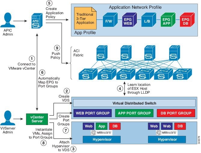
Cisco Application Policy Infrastructure Controller (APIC) integrates with third-party VM managers (VMMs)—such as VMware vCenter—to extend the benefits of Cisco Application Centric Infrastructure (ACI) to the virtualized infrastructure. Cisco APIC enables the administrator to use Cisco ACI policies inside the VMM system.
The following modes of Cisco ACI and VMware VMM integration are supported:
-
VMware VDS: When integrated with Cisco ACI, the VMware vSphere Distributed Switch (VDS) enables you to configure VM networking in the Cisco ACI fabric.
-
Cisco ACI Virtual Edge: For information about how to install and configure Cisco ACI Virtual Edge, see the Cisco ACI Virtual Edge Installation Guide and the Cisco ACI Virtual Edge Configuration Guide on Cisco.com.
-
Cisco Application Virtual Switch (AVS): For information about how to install and configure Cisco AVS with Cisco ACI, see Cisco AVS documentation on Cisco.com.
 Note |
When a Cisco APIC is connected to a VMware vCenter with many folders, you may see a delay when pushing new port groups from the Cisco APIC to the VMWare vCenter. |
Cisco APIC Supported VMware VDS Versions
See the Cisco ACI Virtualization Compatibility Matrix for information about the compatibility of VMware components with Cisco APIC.
Note |
VMware vSphere version 6.7 includes vCenter 6.7, ESXi 6.7, and DVS 6.6. |
Note |
When adding additional VMware ESXi hosts to the VMM domain with VMware vSphere Distributed Switch (VDS), ensure that the version of ESXi host is compatible with the Distributed Virtual Switch (DVS) version already deployed in the vCenter. For more information about VMware VDS compatibility requirements for ESXi hosts, see the VMware documentation. If the ESXi host version is not compatible with the existing DVS version, vCenter will not be able to add the ESXi host to the DVS, and an incompatibility error will occur. Modification of the existing DVS version setting from the Cisco APIC is not possible. To lower the DVS version in the vCenter, you need to remove and reapply the VMM domain configuration with a lower setting. |
Important |
If you have ESXi 6.5 hosts running UCS B-Series or C-Series server with VIC cards, some of the vmnics may go down on a port state event, such as a link flap or a TOR reload. To prevent this problem, do not use the default eNIC driver but install it from the VMware website: https://my.vmware.com/web/vmware/details?downloadGroup=DT-ESXI65-CISCO-NENIC-1020&productId=614. |
Guidelines for Upgrading VMware DVS from 5.x to 6.x and VMM Integration
This section describes the guidelines for upgrading VMware Distributed Virtual Switch (DVS) from 5.x to 6.x and VMM integration.
-
DVS versioning is only applicable to the VMware DVS and not the Cisco Application Virtual Switch (AVS). DVS upgrades are initiated from VMware vCenter, or the relevant orchestration tool and not ACI. The Upgrade Version option appears grayed out for AVS switches within vCenter.
-
If you are upgrading the DVS from 5.x to 6.x, you must upgrade the vCenter Server to version 6.0 and all hosts connected to the distributed switch to ESXi 6.0. For full details on upgrading your vCenter and Hypervisor hosts, see VMware's upgrade documentation. To upgrade the DVS go to the Web Client: .
-
There is no functional impact on the DVS features, capability, performance and scale if the DVS version shown in vCenter does not match the VMM domain DVS version configured on the APIC. The APIC and VMM Domain DVS Version is only used for initial deployment.
Guidelines for VMware VDS Integration
Follow the guidelines in this section when integrating VMware vSphere Distributed Switch (VDS) into Cisco Application Centric Infrastructure (ACI).
-
Do not change the following settings on a VMware VDS configured for VMM integration:
-
VMware vCenter hostname (if you are using DNS).
-
VMware vCenter IP address (if you are using IP).
-
VMware vCenter credentials used by Cisco APIC.
-
Data center name
-
Folder, VDS, or portgroup name.
-
Folder structure containing the VMware VDS.
For example, do not put the folder in another folder.
-
Uplink port-channel configuration, including LACP/port channel, LLDP, and CDP configuration
-
VLAN on a portgroup
-
Active uplinks for portgroups pushed by Cisco APIC.
-
Security parameters (promiscuous mode, MAC address changes, forged transmits) for portgroups pushed by Cisco APIC.
-
-
Use supported versions of VMware vCenter/vSphere with the version of Cisco ACI that you are running.
-
If you are adding or removing any portgroups, use Cisco APIC or the Cisco ACI vCenter plug-in in VMware vCenter.
-
Know that Cisco APIC may overwrite some changes that are made in VMware vCenter.
For example, when Cisco APIC updates a portgroup, port binding, promiscuous mode, and load-balancing can be overwritten
Mapping Cisco ACI and VMware Constructs
|
Cisco ACI Terms |
VMware Terms |
|---|---|
|
Endpoint group (EPG) |
Port group |
|
LACP Active |
|
|
LACP Passive |
|
|
MAC Pinning |
|
|
MAC Pinning-Physical-NIC-Load |
|
|
Static Channel - Mode ON |
|
|
Virtual Machine Manager (VMM) Domain |
vSphere Distributed Switch (VDS) |
|
VM controller |
vCenter (Datacenter) |
VMware VDS Parameters Managed By APIC
VDS Parameters Managed by APIC
See the section Mapping Cisco ACI and VMware Constructs in this guide for a table of corresponding Cisco Application Centric Infrastructure (ACI) and VMware terminology.
|
VMware VDS |
Default Value |
Configurable Using Cisco APIC Policy? |
|---|---|---|
|
Name |
VMM domain name |
Yes (Derived from Domain) |
|
Description |
"APIC Virtual Switch" |
No |
|
Folder Name |
VMM domain name |
Yes (Derived from Domain) |
|
Version |
Highest supported by vCenter |
Yes |
|
Discovery Protocol |
LLDP |
Yes |
|
Uplink Ports and Uplink Names |
8 |
No |
|
Uplink Name Prefix |
uplink |
No |
|
Maximum MTU |
9000 |
Yes |
|
LACP policy |
disabled |
Yes |
|
Port mirroring |
0 sessions |
Yes |
|
Alarms |
2 alarms added at the folder level |
No |
VDS Port Group Parameters Managed by APIC
|
VMware VDS Port Group |
Default Value |
Configurable using APIC Policy |
|---|---|---|
|
Name |
Tenant Name | Application Profile Name | EPG Name |
Yes (Derived from EPG) |
|
Port binding |
Static binding |
No |
|
VLAN |
Picked from VLAN pool |
Yes |
|
Load balancing algorithm |
Derived based on port-channel policy on APIC |
Yes |
|
Promiscuous mode |
Disabled |
Yes |
|
Forged transmit |
Disabled |
Yes |
|
Mac change |
Disabled |
Yes |
|
Block all ports |
False |
No |
 Feedback