The documentation set for this product strives to use bias-free language. For the purposes of this documentation set, bias-free is defined as language that does not imply discrimination based on age, disability, gender, racial identity, ethnic identity, sexual orientation, socioeconomic status, and intersectionality. Exceptions may be present in the documentation due to language that is hardcoded in the user interfaces of the product software, language used based on RFP documentation, or language that is used by a referenced third-party product. Learn more about how Cisco is using Inclusive Language.
A tenant (fvTenant) is a logical container for application policies that enable an administrator to exercise domain-based access control. A
tenant represents a unit of isolation from a policy perspective, but it does not represent a private network. Tenants can
represent a customer in a service provider setting, an organization or domain in an enterprise setting, or just a convenient
grouping of policies. The following figure provides an overview of the tenant portion of the management information tree (MIT).
Figure 1. Tenants
Tenants can be isolated from one another or can share resources. The primary elements that the tenant contains are filters,
contracts, outside networks, bridge domains, Virtual Routing and Forwarding (VRF) instances, and application profiles that
contain endpoint groups (EPGs). Entities in the tenant inherit its policies. VRFs are also known as contexts; each VRF can
be associated with multiple bridge domains.
Note
In the APIC GUI under the tenant navigation path, a VRF (context) is called a private network.
Tenants are logical
containers for application policies. The fabric can contain multiple tenants.
You must configure a tenant before you can deploy any Layer 4 to Layer 7
services. The ACI fabric supports IPv4, IPv6, and dual-stack configurations for
tenant networking.
Routing Within the
Tenant
The Application Centric Infrastructure (ACI) fabric provides tenant default gateway functionality and routes between the
fabric virtual extensible local area (VXLAN) networks. For each tenant, the fabric provides a virtual default gateway or Switched
Virtual Interface (SVI) whenever a subnet is created on the APIC. This spans any switch that has a connected endpoint for
that tenant subnet. Each ingress interface supports the default gateway interface and all of the ingress interfaces across
the fabric share the same router IP address and MAC address for a given tenant subnet.
The ACI fabric provides tenant default gateway functionality that routes between the ACI fabric VXLAN networks. For each tenant, the fabric provides a virtual default gateway that spans all of the leaf switches
assigned to the tenant. It does this at the ingress interface of the first leaf switch connected to the endpoint. Each ingress
interface supports the default gateway interface. All of the ingress interfaces across the fabric share the same router IP
address and MAC address for a given tenant subnet.
The ACI fabric decouples the tenant endpoint address, its identifier, from the location of the endpoint that is defined by its locator
or VXLAN tunnel endpoint (VTEP) address. Forwarding within the fabric is between VTEPs. The following figure shows decoupled
identity and location in ACI.
Figure 2. ACI Decouples Identity and Location
VXLAN uses VTEP devices to map tenant end devices to VXLAN segments and to perform VXLAN encapsulation and de-encapsulation.
Each VTEP function has two interfaces:
A switch interface on the local LAN segment to support local endpoint communication through bridging
An IP interface to the transport IP network
The IP interface has a unique IP address that identifies the VTEP device on the transport IP network known as the infrastructure
VLAN. The VTEP device uses this IP address to encapsulate Ethernet frames and transmit the encapsulated packets to the transport
network through the IP interface. A VTEP device also discovers the remote VTEPs for its VXLAN segments and learns remote MAC
Address-to-VTEP mappings through its IP interface.
The VTEP in ACI maps the internal tenant MAC or IP address to a location using a distributed mapping database. After the VTEP completes a
lookup, the VTEP sends the original data packet encapsulated in VXLAN with the destination address of the VTEP on the destination
leaf switch. The destination leaf switch de-encapsulates the packet and sends it to the receiving host. With this model, ACI
uses a full mesh, single hop, loop-free topology without the need to use the spanning-tree protocol to prevent loops.
The VXLAN segments are independent of the underlying network topology; conversely, the underlying IP network between VTEPs
is independent of the VXLAN overlay. It routes the encapsulated packets based on the outer IP address header, which has the
initiating VTEP as the source IP address and the terminating VTEP as the destination IP address.
The following figure shows how routing within the tenant is done.
Figure 3. Layer 3 VNIDs Transport ACI Inter-subnet Tenant Traffic
For each tenant VRF in the fabric, ACI assigns a single L3 VNID. ACI transports traffic across the fabric according to the L3 VNID. At the egress leaf switch, ACI
routes the packet from the L3 VNID to the VNID of the egress subnet.
Traffic arriving at the fabric ingress that is sent to the ACI fabric default gateway is routed into the Layer 3 VNID. This provides very efficient forwarding in the fabric for traffic
routed within the tenant. For example, with this model, traffic between 2 VMs belonging to the same tenant, on the same physical
host, but on different subnets, only needs to travel to the ingress switch interface before being routed (using the minimal
path cost) to the correct destination.
To distribute external routes within the fabric, ACI route reflectors use multiprotocol BGP (MP-BGP). The fabric administrator provides the autonomous system (AS) number and
specifies the spine switches that become route reflectors.
Note
Cisco ACI does not support IP fragmentation. Therefore, when you configure Layer 3 Outside (L3Out) connections to external routers,
or Multi-Pod connections through an Inter-Pod Network (IPN), it is recommended that the interface MTU is set appropriately
on both ends of a link.
IGP Protocol Packets (EIGRP, OSPFv3) are constructed by components based on the Interface MTU size. In Cisco ACI, if the CPU MTU size is less than the Interface MTU size and if the constructed packet size is greater than the CPU MTU,
then the packet is dropped by the kernal, especially in IPv6. To avoid such control packet drops always configure the same
MTU values on both the control plane and on the interface.
On some platforms, such as Cisco ACI, Cisco NX-OS, and Cisco IOS, the configurable MTU value does not take into account the Ethernet headers (matching IP MTU,
and excluding the 14-18 Ethernet header size), while other platforms, such as IOS-XR, include the Ethernet header in the configured
MTU value. A configured value of 9000 results in a max IP packet size of 9000 bytes in Cisco ACI, Cisco NX-OS, and Cisco IOS, but results in a max IP packet size of 8986 bytes for an IOS-XR untagged interface.
For the appropriate MTU values for each platform, see the relevant configuration
guides.
We highly recommend that you test the MTU using CLI-based commands. For example, on
the Cisco NX-OS CLI, use a command such as ping 1.1.1.1 df-bit packet-size 9000 source-interface
ethernet 1/1.
Router Peering and
Route Distribution
As shown in the figure
below, when the routing peer model is used, the leaf switch interface is
statically configured to peer with the external router’s routing protocol.
Figure 4. Router
Peering
The routes that are
learned through peering are sent to the spine switches. The spine switches act
as route reflectors and distribute the external routes to all of the leaf
switches that have interfaces that belong to the same tenant. These routes are
longest prefix match (LPM) summarized addresses and are placed in the leaf
switch's forwarding table with the VTEP IP address of the remote leaf switch
where the external router is connected. WAN routes have no forwarding proxy. If
the WAN routes do not fit in the leaf switch's forwarding table, the traffic is
dropped. Because the external router is not the default gateway, packets from
the tenant endpoints (EPs) are sent to the default gateway in the ACI fabric.
Bridged Interface to
an External Router
As shown in the figure below, when the leaf switch interface is configured as a bridged
interface, the default gateway for the tenant VNID is the external router.
Figure 5. Bridged External Router
The ACI fabric is
unaware of the presence of the external router and the
APIC statically assigns the leaf switch
interface to its EPG.
Configuring Route
Reflectors
ACI fabric route reflectors use multiprotocol BGP (MP-BGP) to distribute external routes within the fabric. To enable route
reflectors in the ACI fabric, the fabric administrator must select the spine switches that will be the route reflectors, and
provide the autonomous system (AS) number. It is recommended to configure at least two spine nodes per pod as MP-BGP route
reflectors for redundancy.
After route reflectors are enabled in the ACI fabric, administrators can configure connectivity to external networks through
leaf nodes using a component called Layer 3 Out (L3Out). A leaf node configured with an L3Out is called a border leaf. The
border leaf exchanges routes with a connected external device via a routing protocol specified in the L3Out. You can also
configure static routes via L3Outs.
After both L3Outs and spine route reflectors are deployed, border leaf nodes learn external routes via L3Outs, and those external
routes are distributed to all leaf nodes in the fabric via spine MP-BGP route reflectors.
Check the Verified Scalability Guide for Cisco APIC for your release to find the maximum number of routes supported by a leaf.
Configuring External Connectivity Using a Layer 3 Out
This section provides a step-by-step configuration required for the ACI fabric to connect to an external routed network through
L3Outs and MP-BGP route reflectors.
This example uses Open Shortest Path First (OSPF) as the routing protocol in an L3Out under the 'mgmt' tenant.
Configuring an MP-BGP Route Reflector Using the GUI
Procedure
Step 1
On the menu bar, choose System > System Settings.
Step 2
In the Navigation pane, right-click BGP Route Reflector, and click Create Route Reflector Node Policy EP.
Step 3
In the
Create
Route Reflector Node Policy EP dialog box, from the
Spine
Node drop-down list, choose the appropriate spine node. Click
Submit.
Note
Repeat the
above steps to add additional spine nodes as required.
The spine
switch is marked as the route reflector node.
Step 4
In the BGP Route Reflector properties area, in the Autonomous System Number field, choose the appropriate number. Click Submit.
Note
The autonomous
system number must match the leaf connected router configuration if Border
Gateway Protocol (BGP) is configured on the router. If you are using routes
learned using static or Open Shortest Path First (OSPF), the autonomous system
number value can be any valid value.
Step 5
On the menu bar, choose Fabric > Fabric Policies > POD Policies.
Step 6
In the
Navigation pane, expand and right-click
Policy
Groups, and click
Create
POD Policy Group.
Step 7
In the
Create
POD Policy Group dialog box, in the
Name field, enter the name of a pod policy group.
Step 8
In the
BGP
Route Reflector Policy drop-down list, choose the appropriate
policy (default). Click
Submit.
The BGP
route reflector policy is associated with the route reflector pod policy group,
and the BGP process is enabled on the leaf switches.
Step 9
In the
Navigation pane, choose
Pod
Policies > Profiles > default. In the
Work pane, from the
Fabric
Policy Group drop-down list, choose the pod policy that was created
earlier. Click
Submit.
The pod
policy group is now applied to the fabric policy group.
Configuring an
MP-BGP Route Reflector for the ACI Fabric
To distribute routes
within the ACI fabric, an MP-BGP process must first be operating, and the spine
switches must be configured as BGP route reflectors.
The following is an example of an MP-BGP route reflector configuration:
Note
In this example, the BGP fabric ASN is 100. Spine switches 104 and
105 are chosen as MP-BGP route-reflectors.
Verifying the MP-BGP
Route Reflector Configuration
Procedure
Step 1
Verify the
configuration by performing the following actions:
Use secure
shell (SSH) to log in as an administrator to each leaf switch as required.
Enter the
show
processes | grep bgp command to verify the state is S.
If the
state is NR (not running), the configuration was not successful.
Step 2
Verify that the
autonomous system number is configured in the spine switches by performing the
following actions:
Use the SSH
to log in as an administrator to each spine switch as required.
Execute the
following commands from the shell window
Example:
cd
/mit/sys/bgp/inst
Example:
grep asn summary
The
configured autonomous system number must be displayed. If the autonomous system
number value displays as 0, the configuration was not successful.
Creating an OSPF L3Out for Management Tenant Using the GUI
You must
verify that the router ID and the logical interface profile IP address are
different and do not overlap.
The following steps are for creating an OSPF L3Out for a management tenant. To create an OSPF L3Out for a tenant, you must
choose a tenant and create a VRF for the tenant.
For more details, see Cisco APIC and Transit Routing.
Procedure
Step 1
On the menu bar, choose Tenants > mgmt.
Step 2
In the Navigation pane, expand Networking > L3Outs.
Step 3
Right-click L3Outs, and click Create L3Out.
The Create L3Out wizard appears.
Step 4
In the Identity window in the Create L3Out wizard, perform the following actions:
In the Name field, enter a name (RtdOut).
In the VRF field, from the drop-down list, choose the VRF (inb).
Note
This step associates the routed outside with the in-band VRF.
From the L3 Domain drop-down list, choose the appropriate domain.
Check the OSPF check box.
In the OSPF Area ID field, enter an area ID.
In the OSPF Area Control field, check the appropriate check box.
In the OSPF Area Type field, choose the appropriate area type.
In the OSPF Area Cost field, choose the appropriate value.
Click Next.
The Nodes and Interfaces window appears.
Step 5
In the Nodes and Interfaces window, perform the following actions:
Uncheck the Use Defaults box.
This allows you to edit the Node Profile Name field.
In the Node Profile Name field, enter a name for the node profile. (borderLeaf).
In the Node ID field, from the drop-down list, choose the first node. (leaf1).
In the Router ID field, enter a unique router ID.
In the Loopback Address field, use a different IP address or leave this field empty if you do not want to use the router ID for the loopback address.
Note
The Loopback Address field is automatically populated with the same entry that you provide in the Router ID field. This is the equivalent of the Use Router ID for Loopback Address option in previous builds. Use a different IP address or leave this field empty if you do not want to use the router ID for
the loopback address.
Enter the appropriate information in the Interface, IP Address, Interface Profile Name and MTU fields for this node, if necessary.
In the Nodes field, click + icon to add a second set of fields for another node.
Note
You are adding a second node ID.
In the Node ID field, from the drop-down list, choose the first node. (leaf1).
In the Router ID field, enter a unique router ID.
In the Loopback Address field, use a different IP address or leave this field empty if you do not want to use the router ID for the loopback address.
Note
The Loopback Address field is automatically populated with the same entry that you provide in the Router ID field. This is the equivalent of the Use Router ID for Loopback Address option in previous builds. Use a different IP address or leave this field empty if you do not want to use the router ID for
the loopback address.
Enter the appropriate information in the Interface, IP Address, Interface Profile Name and MTU fields for this node, if necessary.
Click Next.
The Protocols window appears.
Step 6
In the Protocols window, in the Policy area, click default, then click Next.
The External EPG window appears.
Step 7
In the External EPG window, perform the following actions:
In the Name field, enter a name for the external network (extMgmt).
Uncheck the Default EPG for all external networks field.
The Subnets area appears.
Click + to access the Create Subnet dialog box.
In the Create Subnet dialog box, in the IP address field, enter an IP address and mask for the subnet.
In the Scope field, check the desired check boxes. Click OK.
In the External EPG dialog box, click Finish.
Note
In the Work pane, in the L3Outs area, the L3Out icon (RtdOut) is now displayed.
Creating an OSPF
External Routed Network for a Tenant Using the NX-OS CLI
Configuring external routed network connectivity involves the
following steps:
Create a VRF under Tenant.
Configure L3 networking configuration for the VRF on the border
leaf switches, which are connected to the external routed network. This
configuration includes interfaces, routing protocols (BGP, OSPF, EIGRP),
protocol parameters, route-maps.
Configure policies by creating external-L3 EPGs under tenant and
deploy these EPGs on the border leaf switches. External routed subnets on a VRF
which share the same policy within the ACI fabric form one "External L3 EPG" or
one "prefix EPG".
Configuration is realized in two modes:
Tenant mode: VRF creation and external-L3 EPG configuration
Leaf mode: L3 networking configuration and external-L3 EPG
deployment
The following steps are for creating an OSPF external routed network
for a tenant. To create an OSPF external routed network for a tenant, you must
choose a tenant and then create a VRF for the tenant.
Note
The examples in this section show how to provide external routed
connectivity to the "web" epg in the "OnlineStore" application for tenant
"exampleCorp".
Configure the tenant BD and mark the gateway IP as “public”. The
entry "scope public" makes this gateway address available for advertisement
through the routing protocol for external-L3 network.
Example:
apic1(config-tenant)# bridge-domain exampleCorp_b1
apic1(config-tenant-bd)# vrf member exampleCorp_v1
apic1(config-tenant-bd)# exit
apic1(config-tenant)# interface bridge-domain exampleCorp_b1
apic1(config-tenant-interface)# ip address 172.1.1.1/24 scope public
apic1(config-tenant-interface)# exit
apic1(config-leaf)# router ospf default
apic1(config-leaf-ospf)# vrf member tenant exampleCorp vrf exampleCorp_v1
apic1(config-leaf-ospf-vrf)# area 0.0.0.1 route-map map100 out
apic1(config-leaf-ospf-vrf)# exit
apic1(config-leaf-ospf)# exit
Step 6
Assign the VRF to the interface (sub-interface in this example)
and enable the OSPF area.
Example:
Note
For the sub-interface configuration, the main interface
(ethernet 1/11 in this example) must be converted to an L3 port through “no
switchport” and assigned a vlan-domain (dom_exampleCorp in this example) that
contains the encapsulation VLAN used by the sub-interface. In the sub-interface
ethernet1/11.500, 500 is the encapsulation VLAN.
apic1(config-leaf)# interface ethernet 1/11
apic1(config-leaf-if)# no switchport
apic1(config-leaf-if)# vlan-domain member dom_exampleCorp
apic1(config-leaf-if)# exit
apic1(config-leaf)# interface ethernet 1/11.500
apic1(config-leaf-if)# vrf member tenant exampleCorp vrf exampleCorp_v1
apic1(config-leaf-if)# ip address 157.10.1.1/24
apic1(config-leaf-if)# ip router ospf default area 0.0.0.1
Step 7
Configure the external-L3 EPG policy. This includes the subnet to
match for identifying the external subnet and consuming the contract to connect
with the epg "web".
Example:
apic1(config)# tenant t100
apic1(config-tenant)# external-l3 epg  l3epg100
apic1(config-tenant-l3ext-epg)# vrf member v100
apic1(config-tenant-l3ext-epg)# match ip 145.10.1.0/24
apic1(config-tenant-l3ext-epg)# contract consumer web
apic1(config-tenant-l3ext-epg)# exit
apic1(config-tenant)#exit
A tenant contains policies that enable qualified users domain-based access control. Qualified users can access privileges
such as tenant administration and networking administration.
A user requires read/write privileges for accessing and configuring policies in a domain. A tenant user can have specific
privileges into one or more domains.
In a multitenancy environment, a tenant provides group user access privileges so that resources are isolated from one another
(such as for endpoint groups and networking). These privileges also enable different users to manage different tenants.
Tenant
Creation
A tenant contains
primary elements such as filters, contracts, bridge domains, and application
profiles that you can create after you first create a tenant.
VRF and Bridge
Domains
You can create and
specify a VRF and a bridge domain for the tenant. The defined bridge domain
element subnets reference a corresponding Layer 3 context.
For details about enabling IPv6 Neighbor Discovery seeIPv6 and Neighbor Discovery in Cisco APIC Layer 3 Networking Guide.
Creating a Tenant, VRF, and Bridge Domain Using the GUI
If you have a
public subnet when you configure the routed outside, you must associate the
bridge domain with the outside configuration.
Procedure
Step 1
On the menu bar, choose Tenants > Add Tenant.
Step 2
In the
Create
Tenant dialog box, perform the following tasks:
In the
Name field, enter a name.
Click the
Security Domains + icon to open the
Create Security Domain dialog box.
In the
Name field, enter a name for the security domain.
Click
Submit.
In the
Create Tenant dialog box, check the check box for the
security domain that you created, and click
Submit.
Step 3
In the
Navigation pane, expand
Tenant-name > Networking, and in the
Work pane, drag the
VRF icon to the canvas to open the
Create
VRF dialog box, and perform the following tasks:
In the
Name field, enter a name.
Click
Submit to complete the VRF configuration.
Step 4
In the
Networking pane, drag the
BD icon to the canvas while connecting it to the
VRF icon. In the
Create
Bridge Domain dialog box that displays, perform the following
tasks:
In the
Name field, enter a name.
Click the
L3
Configurations tab.
Expand
Subnets to open the
Create Subnet dialog box, enter the subnet mask in
the
Gateway IP field and click
OK.
Click
Submit to complete bridge domain configuration.
Step 5
In the
Networks pane, drag the
L3 icon down to the canvas while connecting it to
the
VRF icon. In the
Create
Routed Outside dialog box that displays, perform the following
tasks:
In the
Name field, enter a name.
Expand
Nodes And Interfaces Protocol Profiles to open the
Create Node Profile dialog box.
In the
Name field, enter a name.
Expand
Nodes to open the
Select Node dialog box.
In the
Node ID field, choose a node from the drop-down
list.
In the
Router ID field, enter the router ID.
Expand
Static Routes to open the
Create Static Route dialog box.
In the
Prefix field, enter the IPv4 or IPv6 address.
Expand
Next Hop Addresses and in the
Next Hop IP field, enter the IPv4 or IPv6 address.
In the
Preference field, enter a number, then click
UPDATE and then
OK.
In the
Select Node dialog box, click
OK.
In the
Create Node Profile dialog box, click
OK.
Check the
BGP,
OSPF, or
EIGRP check boxes if desired, and click
NEXT. Click
OK
to complete the Layer 3 configuration.
To
confirm L3 configuration, in the
Navigation pane, expand
Networking > VRFs.
Deploying EPGs
Statically Deploying
an EPG on a Specific Port
This topic provides a
typical example of how to statically deploy an EPG on a specific port when
using Cisco
APIC.
Deploying an EPG on a Specific Node or Port Using the GUI
Before you begin
The tenant where you deploy the EPG is already created.
You can create an EPG on a specific node or a specific port on a node.
Procedure
Step 1
Log in to the Cisco APIC.
Step 2
Choose Tenants > tenant.
Step 3
In the left navigation pane, expand tenant, Application Profiles, and the application profile.
Step 4
Right-click Application EPGs and choose Create Application EPG.
Step 5
In the Create Application EPG STEP 1 > Identity dialog box, complete the following steps:
In the Name field, enter a name for the EPG.
From the Bridge Domain drop-down list, choose a bridge domain.
Check the Statically Link with Leaves/Paths check box.
This check box allows you to specify on which port you want to deploy the EPG.
Click Next.
From the Path drop-down list, choose the static path to the destination EPG.
Step 6
In the Create Application EPG STEP 2 > Leaves/Paths dialog box, from the Physical Domain drop-down list, choose a physical domain.
Step 7
Complete one of the following sets of steps:
Option
Description
If you want to deploy the EPG on...
Then
A node
Expand the Leaves area.
From the Node drop-down list, choose a node.
In the Encap field, enter the appropriate VLAN.
(Optional) From the Deployment Immediacy drop-down list, accept the default On Demand or choose Immediate.
(Optional) From the Mode drop-down list, accept the default Trunk or choose another mode.
A port on the node
Expand the Paths area.
From the Path drop-down list, choose the appropriate node and port.
(Optional) In the Deployment Immediacy field drop-down list, accept the default On Demand or choose Immediate.
(Optional) From the Mode drop-down list, accept the default Trunk or choose another mode.
In the Port Encap field, enter the secondary VLAN to be deployed.
(Optional) In the Primary Encap field, enter the primary VLAN to be deployed.
Step 8
Click Update and click Finish.
Step 9
In the left navigation pane, expand the EPG that you created.
Step 10
Complete one of the following actions:
If you created the EPG on a node, click Static Leafs, and in the work pane view details of the static binding paths.
If you created the EPG on a port of the node, click Static Ports, and in the work pane view details of the static binding paths.
Deploying an EPG
on a Specific Port with APIC Using the NX-OS Style CLI
This procedure deploys an EPG on a specific port with Cisco Application Policy Infrastructure
Controller (APIC) using the NX-OS-style CLI.
Note
Do not mix using the GUI and the CLI when configuring per-interface on the Cisco APIC. Configurations that you perform in the GUI might only partially work in the NX-OS-style CLI.
Creating Domains,
Attach Entity Profiles, and VLANs to Deploy an EPG on a Specific Port
This topic provides a
typical example of how to create physical domains, Attach Entity Profiles
(AEP), and VLANs that are mandatory to deploy an EPG on a specific port.
All endpoint groups (EPGs) require a domain. Interface policy groups must also be associated with Attach Entity Profile (AEP),
and the AEP must be associated with a domain, if the AEP and EPG have to be in same domain. Based on the association of EPGs
to domains and of interface policy groups to domains, the ports and VLANs that the EPG uses are validated. The following domain
types associate with EPGs:
Application EPGs
Layer 3 external outside network instance EPGs
Layer 2 external outside network instance EPGs
Management EPGs for out-of-band and in-band access
The APIC checks if an EPG is associated with one or more of these types of domains. If the EPG is not associated, the system
accepts the configuration but raises a fault. The deployed configuration may not function properly if the domain association
is not valid. For example, if the VLAN encapsulation is not valid for use with the EPG, the deployed configuration may not
function properly.
Note
EPG association with the AEP without static binding does not work in a scenario when you configure the EPG as Trunk under the AEP with one end point under the same EPG supporting Tagging and the other end point in the same EPG does not support
VLAN tagging. While associating AEP under the EPG, you can configure it as Trunk, Access (Tagged) or Access (Untagged).
Creating Domains,
and VLANS to Deploy an EPG on a Specific Port Using the GUI
Before you begin
The tenant
where you deploy the EPG is already created.
An EPG is
statically deployed on a specific port.
Procedure
Step 1
On the menu bar, click Fabric > Access Policies.
Step 2
In the
Navigation pane, click
Quick
Start.
Step 3
In the Work pane, click Configure an Interface, PC, and vPC.
Step 4
In the Configure an Interface, PC, and vPC dialog box, click the + icon to select switches and perform the following actions:
From the Switches drop-down list, check the check box for the desired switch.
In the Switch Profile Name field, a switch name is automatically populated.
Note
Optionally, you can enter a modified name.
Click the + icon to configure the switch interfaces.
In the Interface Type field, click the Individual radio button.
In the Interfaces field, enter the range of desired interfaces.
In the Interface Selector Name field, an interface name is automatically populated.
Note
Optionally, you can enter a modified name.
In the Interface Policy Group field, choose the Create One radio button.
From the Link Level Policy drop-down list, choose the appropriate link level policy.
Note
Create additional policies as desired, otherwise the default policy settings are available.
From the Attached Device Type field, choose the appropriate device type.
In the Domain field, click the Create One radio button.
In the Domain Name field, enter a domain name.
In the VLAN field, click the Create One radio button.
In the VLAN Range field, enter the desired VLAN range. Click Save, and click Save again.
Click Submit.
Step 5
On the menu bar, click Tenants. In the Navigation pane, expand the appropriate Tenant_name > Application Profiles > Application EPGs > EPG_name and perform the following actions:
Right-click Domains (VMs and Bare-Metals), and click Add Physical Domain Association.
In the Add Physical Domain Association dialog box, from the Physical Domain Profile drop-down list, choose the appropriate domain.
Click Submit.
The AEP is associated with a specific port on a node and with a domain. The physical domain is associated with the VLAN pool
and the Tenant is associated with this physical domain.
The switch profile and the interface profile are created. The policy group is created in the port block under the interface
profile. The AEP is automatically created, and it is associated with the port block and with the domain. The domain is associated
with the VLAN pool and the Tenant is associated with the domain.
Creating AEP,
Domains, and VLANs to Deploy an EPG on a Specific Port Using the NX-OS Style
CLI
Before you begin
The tenant
where you deploy the EPG is already created.
Deploying an
Application EPG through an AEP or Interface Policy Group to Multiple
Ports
Through the APIC
Advanced GUI and REST API, you can associate attached entity profiles directly
with application EPGs. By doing so, you deploy the associated application EPGs
to all those ports associated with the attached entity profile in a single
configuration.
Through the APIC REST API or the NX-OS style CLI, you can deploy an application EPG to multiple ports through an Interface
Policy Group.
Deploying an EPG through an AEP to Multiple Interfaces Using the APIC GUI
You can quickly
associate an application with an attached entity profile to quickly deploy that
EPG over all the ports associated with that attached entity profile.
Before you begin
The target
application EPG is created.
The VLAN pools has been created containing the range of VLANs you wish to use for EPG Deployment on the AEP.
The physical domain has been created and linked to the VLAN Pool and AEP.
The target
attached entity profile is created and is associated with the ports on which
you want to deploy the application EPG.
Procedure
Step 1
Navigate to
the target attached entity profile.
Open the page for the attached entity profile to use. In the GUI, click Fabric > Access Policies > Policies > Global > Attachable Access Entity Profiles.
Click the
target attached entity profile to open its Attachable Access Entity Profile
window.
Step 2
Click the
Show Usage
button to view the leaf switches and interfaces associated with this attached
entity profile.
the
application EPGs associated with this attached entity profile are deployed to
all the ports on all the switches associated with this attached entity profile.
Step 3
Use the
Application
EPGs table to associate the target application EPG with this attached
entity profile. Click
+ to add
an application EPG entry. Each entry contains the following fields:
Field
Action
Application
EPGs
Use the
drop down to choose the associated Tenant, Application Profile, and target
application EPG.
Encap
Enter the
name of the VLAN over which the target application EPG will communicate.
Primary
Encap
If the
application EPG requires a primary VLAN, enter the name of the primary VLAN.
Mode
Use the
drop down to specify the mode in which data is transmitted:
Trunk -- Choose if
traffic from the host is tagged with a VLAN ID.
Access -- Choose if
traffic from the host is tagged with an 802.1p tag.
Access Untagged --
Choose if the traffic from the host is untagged.
Step 4
Click
Submit.
the
application EPGs associated with this attached entity profile are deployed to
all the ports on all the switches associated with this attached entity profile.
Deploying an EPG
through an Interface Policy Group to Multiple Interfaces Using the NX-OS Style
CLI
In the NX-OS CLI,
an attached entity profile is not explicitly defined to associate with an EPG
for rapid deployment; instead the interface policy group is defined, assigned a
domain, applied to all the ports associated with a VLAN and configured to
include the application EPG to be deployed over that VLAN.
Before you begin
The target application EPG is created.
The VLAN pools has been created containing the range of VLANs you wish to use for EPG Deployment on the AEP.
The physical domain has been created and linked to the VLAN Pool and AEP.
The target attached entity profile is created and is associated with the ports on which you want to deploy the application
EPG.
Procedure
Step 1
Associate the target EPG with the interface policy group.
The sample command sequence specifies an interface policy group pg3 associated with VLAN domain, domain1, and with VLAN 1261. The application EPG, epg47 is deployed to all interfaces associated with this policy group.
Check the target ports to ensure deployment of the policies of the interface policy group associated with application EPG.
The output of the sample show command sequence indicates that policy group pg3 is deployed on Ethernet port 1/20 on leaf switch 1017.
Example:
 apic1# show run leaf 1017 int eth 1/20
# Command: show running-config leaf 1017 int eth 1/20
# Time: Mon Jun 27 22:12:10 2016
  leaf 1017
    interface ethernet 1/20
      policy-group pg3
      exit
    exit
ifav28-ifc1#
Deploying an EPG
through an AEP to Multiple Interfaces Using the REST API
The interface selectors in the AEP enable you to configure multiple paths for an AEPg. The following can be selected:
A node or a group of nodes
An interface or a group of interfaces
The interfaces consume an interface policy group (and so an infra:AttEntityP).
The infra:AttEntityP is associated to the AEPg, thus specifying the VLANs to use.
An infra:AttEntityP can be associated with multiple AEPgs with different VLANs.
When you associate the infra:AttEntityP with the AEPg, as in 3, this deploys the AEPg on the nodes selected in 1, on the interfaces
in 2, with the VLAN provided by 3.
In this example, the AEPg uni/tn-Coke/ap-AP/epg-EPG1 is deployed on interfaces 1/10, 1/11, and 1/12 of nodes 101 and 102, with vlan-102.
Before you begin
Create the target application EPG (AEPg).
Create the VLAN pool containing the range of VLANs you wish to use for EPG deployment with the Attached Entity Profile (AEP).
Create the physical domain and link it to the VLAN pool and AEP.
Procedure
To deploy an AEPg on selected nodes and interfaces, send a post with XML such as the following:
Using
Microsegmentation with Network-based Attributes on Bare Metal
You can use Cisco
APIC to configure Microsegmentation with Cisco ACI to create a new,
attribute-based EPG using a network-based attribute, a MAC address or one or
more IP addresses. You can configure Microsegmentation with Cisco ACI using
network-based attributes to isolate VMs or physical endpoints within a single
base EPG or VMs or physical endpoints in different EPGs.
Using an
IP-based Attribute
You can use an
IP-based filter to isolate a single IP address, a subnet, or multiple of
noncontiguous IP addresses in a single microsegment. You might want to isolate
physical endpoints based on IP addresses as a quick and simply way to create a
security zone, similar to using a firewall.
Using a
MAC-based Attribute
You can use a
MAC-based filter to isolate a single MAC address or multiple MAC addresses. You
might want to do this if you have a server sending bad traffic int he network.
By creating a microsegment with a MAC-based filter, you can isolate the server.
Configuring
Network-based Microsegmented EPGs in a Bare-Metal environment Using the
GUI
You can use Cisco
APIC to configure microsegmentation to put physical endpoint devices that
belong to different base EPGs or the same EPG into a new attribute-based EPG.
Procedure
Step 1
Log into the Cisco APIC.
Step 2
Choose Tenants and then choose the tenant within which you want to create a microsegment.
Step 3
In the tenant
navigation pane, expand the tenant folder, the
Application Profiles folder, the
profile folder, and the
Application EPGs folder.
Step 4
Take one of
the following actions:
If you want to put physical
endpoint devices from the same base EPG into a new, attribute-based EPG, click
the base EPG containing the physical endpoint devices.
If you want to put physical
endpoint devices from different base EPGs into a new, attribute-based EPG,
click one of the base EPG containing the physical endpoint devices.
The
properties for the base EPG appear in the work pane.
Step 5
In the work pane, click the Operational tab at the top right of the screen.
Step 6
Below the Operational tab, ensure that the Client End-Points tab is active.
The work pane displays all the physical endpoints that belong to the base EPG.
Step 7
Note the IP
address or MAC address for the endpoint device or endpoint devices that you
want to put into a new microsegment.
Step 8
If you want to
put endpoint devices from different base EPGs into a new attribute-based EPG,
repeat Step 4 through Step 7 for each of the base EPGs.
Step 9
In the tenant
navigation pane, right-click the
uSeg
EPGs folder, and then choose
Create
uSeg EPG.
Step 10
Complete the
following series of steps to begin creation of an attribute-based EPG for one
of the groups of endpoint devices:
In the
Create uSeg EPG dialog box, in the
Name field, enter a name.
We
recommend that you choose a name that indicates that the new attribute-based
EPG is a microsegment.
In the
intra-EPG isolation field, select
enforced or
unenforced.
If you
select
enforced,
ACI
prevents all communication between the endpoint devices within this uSeg EPG.
In the
Bridge Domain area, choose a bridge domain from the
drop-down list.
In the
uSeg Attributes area, choose
IP
Address Filter or
MAC Address Filter from the
+ drop-down list on the right side of the dialog
box.
Step 11
Complete one
of the following series of steps to configure the filter.
If you want to
use...
Then...
An IP-based
attribute
In the
Create IP Attribute dialog box, in the
Name field, enter a name.
We
recommend that you choose a name that reflects the filter's function.
In
the
IP Address field, enter an IP address or a subnet
with the appropriate subnet mask.
Click
OK.
(Optional) Create a
second IP Address filter by repeating Step 10 c through Step 11 c.
You
might want to do this to include discontinuous IP addresses in the
microsegment.
In the Create uSeg EPG dialog box, click Submit.
A MAC-based
attribute
In the
Create MAC Attribute dialog box, in the
Name field, enter a name.
We
recommend that you choose a name that reflects the filter's function.
In the
MAC Address field, enter a MAC address.
Click
OK.
In the Create uSeg EPG dialog box, click Submit.
Step 12
Complete the
following steps to associate the uSeg EPG with a physical domain.
In the
navigation pane, ensure that the uSeg EPG folder is open and then open the
container for the microsegment that you just created.
Click
the folder
Domains (VMs and Bare-Metals).
On the right side of the work pane, click Actions and then choose Add Physical Domain Association from the drop-down list.
In the
Add Physical Domain Association dialog box, choose a
profile from the
Physical Domain Profile drop-down list.
In the
Deploy Immediacy area, accept the default
On Demand.
In the Resolution Immediacy area, accept the default Immediate.
Click Submit.
Step 13
Associate
the uSeg EPG with the appropriate leaf switch.
In the
navigation pane, ensure the uSeg EPG folder is open then click
Static Leafs.
In the
Static Leafs window, click
Actions > Statically Link with
Node
In the
Statically Link With Node dialog, select the leaf node and mode.
Click
Submit.
Step 14
Repeat Step
9 through Step 13 for any other network attribute-based EPGs that you want to
create.
What to do next
Verify that the
attribute-based EPG was created correctly.
If you
configured an IP-based or MAC-based attribute, make sure that traffic is
running on the end pont devices that you put into the new microsegments.
Configuring a
Network-Based Microsegmented EPG in a Bare-Metal Environment Using the NX-OS
Style CLI
This
section describes how to configure microsegmentation with Cisco ACI using
network-based attributes (IP address or MAC address) within a base EPG in a
bare-metal environment.
Procedure
Command or Action
Purpose
Step 1
In the CLI,
enter configuration mode:
Example:
apic1# configure
apic1(config)#
Step 2
Create the
microsegment:
Example:
This
example uses a filter based on an IP address.
apic1(config)# tenant cli-ten1
apic1(config-tenant)# application cli-a1
apic1(config-tenant-app)# epg cli-uepg1 type micro-segmented
apic1(config-tenant-app-uepg)# bridge-domain member cli-bd1
apic1(config-tenant-app-uepg)# attribute cli-upg-att match ip <X.X.X.X>
	#Schemes to express the ip
		 A.B.C.D      IP Address
		 A.B.C.D/LEN  IP Address and mask
Example:
This
example uses a filter based on a MAC address.
apic1(config)# tenant cli-ten1
apic1(config-tenant)# application cli-a1
apic1(config-tenant-app)# epg cli-uepg1 type micro-segmented
apic1(config-tenant-app-uepg)# bridge-domain member cli-bd1
apic1(config-tenant-app-uepg)# attribute cli-upg-att match mac <FF-FF-FF-FF-FF-FF>
#Schemes to express the mac
E.E.E MAC address (Option 1)
EE-EE-EE-EE-EE-EE MAC address (Option 2)
EE:EE:EE:EE:EE:EE MAC address (Option 3)
EEEE.EEEE.EEEE MAC address (Option 4)
Example:
This
example uses a filter based on a MAC address and enforces intra-EPG isolation
between all members of this uSeg EPG:
apic1(config)# tenant cli-ten1
apic1(config-tenant)# application cli-a1
apic1(config-tenant-app)# epg cli-uepg1 type micro-segmented
apic1(config-tenant-app-uepg)# isolation enforced
apic1(config-tenant-app-uepg)# bridge-domain member cli-bd1
apic1(config-tenant-app-uepg)# attribute cli-upg-att match mac <FF-FF-FF-FF-FF-FF>
#Schemes to express the mac
E.E.E MAC address (Option 1)
EE-EE-EE-EE-EE-EE MAC address (Option 2)
EE:EE:EE:EE:EE:EE MAC address (Option 3)
EEEE.EEEE.EEEE MAC address (Option 4)
Step 3
Deploy the
EPG.
Example:
This
example deploys the EPG and bids to the leaf.
IP Address-Based
Microsegmented EPG as a Shared Resource
You can configure an
IP address-based microsegemented EPG as a resource that can be accessed from
both within and without the VRF on which it is located. The method of doing so
is to configure an existing IP address-based microsegmented EPG with a subnet
(assigned a unicast IP address) and enable that subnet for being advertised and
shared by devices located on VRFs other than the one on which this EPG is
native. Then you define an IP attribute with an option enabled that associates
the EPG with the IP address of the shared subnet.
Configuring an
IP-based Microsegmented EPG as a Shared Resource Using the GUI
You can configure
a microsegmented EPG with an IP-Address with 32 bit mask as a shared service,
accessible by clients outside of the VRF and the current fabric.
Before you begin
The following GUI
description of configuring assumes the preconfiguration of an IP address-based
microsegmented EPG configured whose subnet mask is /32.
For
directions on configuring an IP address based EPG in a virtual environment, see
Configuring Microsegmentation with Cisco ACI in the
Cisco
ACI Virtualization Guide.
Procedure
Step 1
Navigate to
the target IP-address-based EPG.
In the
APIC GUI, click
Tenant > tenant_name > uSeg
EPGs > uSeg_epg_name to display the EPG's
Properties dialog.
Step 2
For the target
EPG, configure an IP attribute to match the EPG subnet address.
In
the
Properties dialog, locate the
uSeg Attributes table, and click
+. When prompted, choose
IP
Address Filter to display the
Create IP Attribute dialog.
Enter a
name in the Name field
Check the
box for
Use FV Subnet.
Enabling
this option, indicates that the IP attribute value matches the IP address of a
shared subnet.
Click
Submit.
Step 3
Create a
shared subnet for the target EPG.
With the
folder for the target IP address-based uSeg EPG still open in the APIC
navigation pane, right-click the Subnets
folder and select
Create EPG Subnets.
In the
Default Gateway field, enter the IP address/mask of
the IP address-based microsegmented EPG.
Note
In
all cases the subnet mask must be /32.
In
the context of an IP address-based EPG, you are not actually entering the
default address for a gateway, rather you are entering the IP address for the
shared EPG subnet.
Select
Treat as a virtual IP address.
Under
Scope select
Advertised Externally and
Shared between VRFs.
Click
Submit.
Configuring an
IP-based Microsegmented EPG as a Shared Resource Using the NX-OS CLI
Before you begin
The following GUI description of
configuring assumes the preconfiguration of an IP address-based microsegmented
EPG configured whose subnet mask is /32.
Procedure
Command or Action
Purpose
Step 1
Enable the IP address
microsegmented EPG for shared service by associating the EPG with the IP
address of its subnet.
Example:
apic-1(config)# tenant t0
apic-1(config-tenant-app)# epg cli-epg type micro-segmented
apic-1(config-tenant-app-uepg)# bridge-domain member b0
apic-1(config-tenant-app-uepg)# attribute ip match ip-use-epg-subnet

apic-1(config-tenant-app-uepg)# show run
# Command: show running-config tenant t0 application a0 epg cli-epg type micro-segmented
# Time: Thu Sep 22 00:17:07 2016
  tenant t0
    application a0
      epg cli-epg type micro-segmented
        bridge-domain member b0
        attribute ip match ip-use-epg-subnet
        exit
      exit
    Exit
In this example, microsegmented EPG, cli-epg, is configured with
the
ip-use-epg-subnet
option (useFvSubnet), thus associating the EPG with the
IP address of its subnet. APIC then advertises that subnet address, thus making
the EPG accessible as a service to devices on VRFs other than the one on which
the EPG is native.
Step 2
Deploy the EPG to a leaf.
In this example, microsegmented EPG, cli-epg, is deployed to leaf
102.
apic-1(config)# leaf 102
apic-1(config-leaf)# deploy-epg tenant t0 application a0 epg cli-epg type micro-segmented

apic-1(config-leaf)# show run
# Command: show running-config leaf 102
# Time: Thu Sep 22 00:18:46 2016
  leaf 102
    deploy-epg tenant t0 application a0 epg cli-epg type micro-segmented
Configuring an
IP-based Microsegmented EPG as a Shared Resource Using the REST API
You can configure
a microsegmented EPG with an IP-Address with 32 bit mask as a shared service,
accessible by clients outside of the VRF and the current fabric.
Procedure
To configure an IP address-attribute microsegmented EPG epg3 with a shared subnet, with an IP address and 32-bit mask, send a post with XML such as the following example. In the IP
attributes, the attribute usefvSubnet is set to "yes."
Unconfiguring an
IP-based Microsegmented EPG as a Shared Resource Using the GUI
When you
unconfigure an IP address-Based microsegmented EPG as a shared service, you
must remove the shared subnet and also disable the option to use that subnet as
a shared resource.
Before you begin
Before you
unconfigure an IP address-based microsegmented EPG as a shared service, you
should know the following:
Know which
subnet is configured as a shared service address for the IP address-based
microsegmented EPG.
Know which IP
attribute is configured with the
Use
FV Subnet
option enabled.
Procedure
Step 1
Remove subnet
from the IP addressed-based microsegmented EPG.
With the
folder for the target IP address-based uSeg EPG still open in the APIC
navigation pane, click the Subnets folder.
In the
Subnets window, select the subnet that is advertised
and shared with other VRFs and click
Actions
> Delete. then
Click
Yes to confirm the deletion.
Step 2
Disable the
Use
FV Subnet option.
With the
folder for the target IP address-based uSeg EPG still open in the APIC
navigation pane, click the name of the micro-segmented EPG to display the to
display the EPG's
Properties dialog.
In
the
Properties dialog, locate the
uSeg Attributes table, and locate the IP attribute
item with the
Use FV Subnet option enabled.
Double-click that item to display the
Edit IP Attribute
dialog.
In
the Edit IP
Attribute dialog, deselect the
Use FV Subnet option.
Assign
another IP address attribute in the IP Address field.
Note
This address must be a unicast address with a 32 bit mask (for
example: 124.124.124.123/32).
Click
Submit.
Unconfiguring an
IP-based Microsegmented EPG as a Shared Resource Using the NX-OS Style
CLI
To unconfigure an
IP address-based microsegmented EPG as a shared service, disable the
ip-use-epg-subnet option for that EPG.
Before you begin
Procedure
Command or Action
Purpose
Disable the
ip-use-epg-subnet option.
Example:
apic-1(config)# tenant t0
apic-1(config-tenant-app)# epg cli-epg type micro-segmented
apic-1(config-tenant-app-uepg)# no attribute ip match ip-use-epg-subnet
apic-1(config-tenant-app-uepg)# exit
apic-1(config-tenant-app)# exit
The example
code disables the ip-use-epg-subnet option for the microsegmented EPG cli-epg.
Unconfiguring an
IP-based Microsegmented EPG as a Shared Resource Using the REST API
You can disable an
IP address-based microsegmented EPG by setting the
usefvSubnet
property to "no."
Procedure
In the API
structure for the microsegmented EPG currently configured as a shared service,
change the value of the usefvSubnet property from "yes" to "no."
In the
example, the IP address-based microsegmented EPG, epg3, is disabled as a shared
service.
As traffic enters the
leaf switch from the front panel interfaces, the packets are marked with the
EPG of the source EPG. The leaf switch then performs a forwarding lookup on the
packet destination IP address within the tenant space. A hit can result in any
of the following scenarios:
A unicast (/32)
hit provides the EPG of the destination endpoint and either the local interface
or the remote leaf switch VTEP IP address where the destination endpoint is
present.
A unicast hit of a
subnet prefix (not /32) provides the EPG of the destination subnet prefix and
either the local interface or the remote leaf switch VTEP IP address where the
destination subnet prefix is present.
A multicast hit
provides the local interfaces of local receivers and the outer destination IP
address to use in the VXLAN encapsulation across the fabric and the EPG of the
multicast group.
Note
Multicast and
external router subnets always result in a hit on the ingress leaf switch.
Security policy enforcement occurs as soon as the destination EPG is known by
the ingress leaf switch.
A miss result in the
forwarding table causes the packet to be sent to the forwarding proxy in the
spine switch. The forwarding proxy then performs a forwarding table lookup. If
it is a miss, the packet is dropped. If it is a hit, the packet is sent to the
egress leaf switch that contains the destination endpoint. Because the egress
leaf switch knows the EPG of the destination, it performs the security policy
enforcement. The egress leaf switch must also know the EPG of the packet
source. The fabric header enables this process because it carries the EPG from
the ingress leaf switch to the egress leaf switch. The spine switch preserves
the original EPG in the packet when it performs the forwarding proxy function.
On the egress leaf
switch, the source IP address, source VTEP, and source EPG information are
stored in the local forwarding table through learning. Because most flows are
bidirectional, a return packet populates the forwarding table on both sides of
the flow, which enables the traffic to be ingress filtered in both directions.
Contracts Contain
Security Policy Specifications
In the ACI security
model, contracts contain the policies that govern the communication between
EPGs. The contract specifies what can be communicated and the EPGs specify the
source and destination of the communications. Contracts link EPGs, as shown
below.
Endpoints in EPG 1
can communicate with endpoints in EPG 2 and vice versa if the contract allows
it. This policy construct is very flexible. There can be many contracts between
EPG 1 and EPG 2, there can be more than two EPGs that use a contract, and
contracts can be reused across multiple sets of EPGs, and more.
There is also
directionality in the relationship between EPGs and contracts. EPGs can either
provide or consume a contract. An EPG that provides a contract is typically a
set of endpoints that provide a service to a set of client devices. The
protocols used by that service are defined in the contract. An EPG that
consumes a contract is typically a set of endpoints that are clients of that
service. When the client endpoint (consumer) tries to connect to a server
endpoint (provider), the contract checks to see if that connection is allowed.
Unless otherwise specified, that contract would not allow a server to initiate
a connection to a client. However, another contract between the EPGs could
easily allow a connection in that direction.
This
providing/consuming relationship is typically shown graphically with arrows
between the EPGs and the contract. Note the direction of the arrows shown
below.
The contract is
constructed in a hierarchical manner. It consists of one or more subjects, each
subject contains one or more filters, and each filter can define one or more
protocols.
Figure 6. Contract
Filters
The following figure
shows how contracts govern EPG communications.
Figure 7. Contracts
Determine EPG to EPG Communications For example, you may define a filter called HTTP that specifies TCP
port 80 and port 8080 and another filter called HTTPS that specifies TCP port
443. You might then create a contract called webCtrct that has two sets of
subjects. openProv and openCons are the subjects that contain the HTTP filter.
secureProv and secureCons are the subjects that contain the HTTPS filter. This
webCtrct contract can be used to allow both secure and non-secure web traffic
between EPGs that provide the web service and EPGs that contain endpoints that
want to consume that service.
These same constructs also apply for policies that govern virtual machine hypervisors. When an EPG is placed in a virtual
machine manager (VMM) domain, the APIC downloads all of the policies that are associated with the EPG to the leaf switches
with interfaces connecting to the VMM domain. For a full explanation of VMM domains, see the Virtual Machine Manager Domains chapter of Application Centric Infrastructure Fundamentals. When this policy is created, the APIC pushes it (pre-populates it) to a VMM domain that specifies which switches allow connectivity
for the endpoints in the EPGs. The VMM domain defines the set of switches and ports that allow endpoints in an EPG to connect
to. When an endpoint comes on-line, it is associated with the appropriate EPGs. When it sends a packet, the source EPG and
destination EPG are derived from the packet and the policy defined by the corresponding contract is checked to see if the
packet is allowed. If yes, the packet is forwarded. If no, the packet is dropped.
Contracts consist of 1 or more subjects. Each subject contains 1 or more filters. Each filter contains 1 or more entries.
Each entry is equivalent to a line in an Access Control List (ACL) that is applied on the Leaf switch to which the endpoint
within the endpoint group is attached.
In detail, contracts are comprised of the following items:
Name—All contracts that are consumed by a tenant must have different names (including contracts created under the common tenant
or the tenant itself).
Subjects—A group of filters for a specific application or service.
Filters—Used to classify traffic based upon layer 2 to layer 4 attributes (such as Ethernet type, protocol type, TCP flags
and ports).
Actions—Action to be taken on the filtered traffic. The following actions are supported:
Permit the traffic (regular contracts, only)
Mark the traffic (DSCP/CoS) (regular contracts, only)
Redirect the traffic (regular contracts, only, through a service graph)
Copy the traffic (regular contracts, only, through a service graph or SPAN)
Block the traffic (taboo contracts)
With Cisco APIC Release 3.2(x) and switches with names that end in EX or FX, you can alternatively use a subject Deny action
or Contract or Subject Exception in a standard contract to block traffic with specified patterns.
Log the traffic (taboo contracts and regular contracts)
Aliases—(Optional) A changeable name for an object. Although the name of an object, once created, cannot be changed, the Alias
is a property that can be changed.
Thus, the contract allows more complex actions than just allow or deny. The contract can specify that traffic that matches
a given subject can be re-directed to a service, can be copied, or can have its QoS level modified. With pre-population of
the access policy in the concrete model, endpoints can move, new ones can come on-line, and communication can occur even if
the APIC is off-line or otherwise inaccessible. The APIC is removed from being a single point of failure for the network.
Upon packet ingress to the ACI fabric, security policies are enforced by the concrete model running in the switch.
Three-Tier
Application Deployment
A
filter specifies the data protocols to be allowed or denied by a contract that
contains the filter. A contract can contain multiple subjects. A subject can be
used to realize uni- or bidirectional filters. A unidirectional filter is a
filter that is used in one direction, either from consumer-to-provider (IN) or
from provider-to-consumer (OUT) filter. A bidirectional filter is the same
filter that is used in both directions. It is not reflexive.
Contracts
are policies that enable inter-End Point Group (inter-EPG) communication. These
policies are the rules that specify communication between application tiers. If
no contract is attached to the EPG, inter-EPG communication is disabled by
default. No contract is required for intra-EPG communication because intra-EPG
communication is always allowed.
Application profiles enable you to model application requirements that the APIC then automatically renders in the network and data center infrastructure. The
application profiles enable administrators to approach the resource pool in terms of
applications rather than infrastructure building blocks. The application profile is
a container that holds EPGs that are logically related to one another. EPGs can
communicate with other EPGs in the same application profile and with EPGs in other
application profiles.
To deploy an
application policy, you must create the required application profiles, filters,
and contracts. Typically, the
APIC fabric hosts a three-tier application
within a tenant network. In this example, the application is implemented by
using three servers (a web server, an application server, and a database
server). See the following figure for an example of a three-tier application.
The web server has the
HTTP filter, the application server has the Remote Method Invocation (RMI)
filter, and the database server has the Structured Query Language (SQL) filter.
The application server consumes the SQL contract to communicate with the
database server. The web server consumes the RMI contract to communicate with
the application server. The traffic enters from the web server and communicates
with the application server. The application server then communicates with the
database server, and the traffic can also communicate externally.
Figure 8. Three-Tier
Application Diagram
Parameters to Create
a Filter for http
The parameters to
create a filter for http in this example is as follows:
Parameter Name
Filter for http
Name
http
Number of
Entries
2
Entry Name
Dport-80
Dport-443
Ethertype
IP
Protocol
tcp
tcp
Destination Port
http
https
Parameters to Create
Filters for rmi and sql
The parameters to
create filters for rmi and sql in this example are as follows:
Parameter Name
Filter for rmi
Filter for sql
Name
rmi
sql
Number of
Entries
1
1
Entry Name
Dport-1099
Dport-1521
Ethertype
IP
IP
Protocol
tcp
tcp
Destination Port
1099
1521
Example Application Profile Database
The application profile database in this example is as follows:
EPG
Provided Contracts
Consumed Contracts
web
web
rmi
app
rmi
sql
db
sql
--
Creating an
Application Profile Using the GUI
Procedure
Step 1
On the menu bar,
choose
TENANTS. In the
Navigation pane, expand the tenant, right-click
Application Profiles, and click
Create
Application Profile.
Step 2
In the
Create
Application Profile dialog box, in the
Name field, add the application profile name
(OnlineStore).
Creating EPGs Using the GUI
The port the EPG uses must belong to one of the VM Managers (VMM) or
physical domains associated with the EPG.
Procedure
Step 1
On the menu bar, choose Tenants and the tenant where you want to create an EPG.
Step 2
In the navigation pane, expand the folder for the tenant, the Application Profiles folder, and the folder for the application profile.
Step 3
Right-click the Application EPG folder, and in the Create Application EPG dialog box, perform the following actions:
In the Name field, add the EPG name (db).
In the Bridge Domain field, choose the bridge domain from the drop-down list (bd1).
Check the Associate to VM Domain Profiles check box. Click Next.
In the STEP 2 > Domains area, expand Associate VM Domain Profiles and from the drop-down list, choose the desired VMM domain.
From the Deployment Immediacy drop-down list, accept the default or choose when policies are deployed from Cisco APIC to the physical leaf switch.
From the Resolution Immediacy drop-down list, choose when policies are deployed from the physical leaf switch to the virtual leaf.
If you have Cisco AVS, choose Immediate or On Demand; if you have Cisco ACI Virtual Edge or VMware VDS, choose Immediate, On Demand, or Pre-provision.
(Optional) In the Delimiter field, enter one of the following symbols: |, ~, !, @, ^, +, or =.
If you do not enter a symbol, the system uses the default | delimiter in the VMware portgroup name.
If you have Cisco ACI Virtual Edge or Cisco AVS, from the Encap Mode drop-down list, choose an encapsulation mode.
You can choose one of the following encapsulation modes:
VXLAN:This overrides the domain's VLAN configuration, and the EPG uses VXLAN encapsulation. However, a fault is for the EPG if
a multicast pool is not configured on the domain.
VLAN: This overrides the domain's VXLAN configuration, and the EPG uses VLAN encapsulation. However, a fault is triggered for
the EPG if a VLAN pool is not configured on the domain.
Auto: This causes the EPG to use the same encapsulation mode as the VMM domain. This is the default configuration.
If you have Cisco ACI Virtual Edge, from the Switching Mode drop-down list, choose native or AVE.
If you choose native, the EPG is switched through the VMware VDS; if you choose AVE, the EPG is switched through the Cisco ACI Virtual Edge. The default is native.
Click Update and then click Finish.
Step 4
In the Create Application Profile dialog box, create two more EPGs. Create the three EPGs—db, app, and web—in the same bridge domain and data center.
Configuring Contracts Using the APIC GUI
Guidelines and Limitations for Contracts and Filters
If your fabric consists of first-generation Cisco Nexus 9300 leaf switches, such as
Cisco Nexus 93128TX, 93120TX, 9396TX, 9396PX, 9372PX, 9372PX-E, 9372TX and 9372TX-E,
only IP as an EtherType match is
supported with contract filters. The capability to match more granular options, such
as IPv4 or IPv6, in the
EtherType field for contract filters is supported only on
leaf switch models with -EX, -FX, or -FX2 at the end of the switch name.
Creating a Filter
Using the GUI
Create three
separate filters. In this example they are HTTP, RMI, SQL. This task shows how
to create the HTTP filter. The task is identical for creating the other
filters.
Before you begin
Verify that the
tenant, network, and bridge domain have been created.
Procedure
Step 1
On the menu bar, choose Tenants. In the Navigation pane, expand the tenant-name > Contracts, right-click Filters, and click Create Filter.
Note
In the Navigation pane, you expand the tenant where you want to add filters.
Step 2
In the
Create
Filter dialog box, perform the following actions:
In the
Name field, enter the filter name (http).
Expand
Entries, and in the
Name field, enter the name (Dport-80).
From the
EtherType drop-down list, choose the EtherType (IP).
From the
IP
Protocol drop-down list, choose the protocol (tcp).
From the
Destination Port/Range drop-down lists, choose
http in the
From and
To fields. (http)
Click
Update, and click
Submit.
The
newly added filter appears in the
Navigation pane and in the
Work pane.
Step 3
Expand
Entries in the
Name field. Follow the same process to add another
entry with HTTPS as the
Destination port, and click
Update.
On the menu bar, choose Tenants and the tenant name on which you want to operate. In the Navigation pane, expand the tenant-name > Contracts.
Step 2
Right-click Standard > Create Contract.
Step 3
In the
Create
Contract dialog box, perform the following tasks:
In the
Name field, enter the contract name (web).
Click the
+ sign next to
Subjects to add a new subject.
In the
Create Contract Subject dialog box, enter a subject
name in the
Name field. (web)
Note
This step
associates the filters created that were earlier with the contract subject.
In the
Filter Chain area, click the
+ sign next to
Filters.
In the
dialog box, from the drop-down menu, choose the filter name (http), and click
Update.
Step 4
In the
Create
Contract Subject dialog box, click
OK.
Step 5
Create two
more contracts for rmi and for sql following the same steps in this procedure.
For the rmi contract, choose the rmi subject and for sql, choose the sql
subject.
Consuming and
Providing Contracts Using the GUI
You can associate
contracts that were created earlier to create policy relationships between the
EPGs.
When you name the provided and consumed contracts, verify that you
give the same name for both provided and consumed contracts.
Procedure
Step 1
Click and drag
across the
APIC
GUI window from the db EPG to the app EPG.
Note
The db, app,
and web EPGs are displayed as icons.
The
Add
Consumed Contract dialog box is displayed.
Step 2
In the
Name field, from the drop-down list, choose
sql contract. Click
OK.
This
step enables the db EPG to provide the sql contract and the app EPG to consume
the sql contract.
Step 3
Click and
drag across the
APIC
GUI screen from the app ePG to the web EPG.
The
Add
Consumed Contract dialog box is displayed.
Step 4
In the
Name field, from the drop-down list, choose
rmi contract. Click
OK.
This
step enables the app EPG to provide the rmi contract and the web EPG to consume
the rmi contract.
Step 5
Click the web
EPG icon, and click the
+ sign in the
Provided Contracts area.
The
Add
Provided Contract dialog box is displayed.
Step 6
In the
Name field, from the drop-down list, choose
web contract. Click
OK. Click
Submit.
You
have created a three-tier application profile called OnlineStore.
Step 7
To verify, in
the
Navigation pane, navigate to and click
OnlineStore under
Application Profiles.
In the
Work pane, you can see the three EPGs app, db, and
web are displayed.
Step 8
In the
Work pane, choose
Operational > Contracts.
You
can see the EPGs and contracts displayed in the order that they are consumed
and provided.
Configuring Contracts Using the NX-OS Style CLI
Configuring
Contracts
Contracts are
configured under a tenant with the following tasks:
Define filters
as access lists
Define the
contract and subjects
Link the
contract to an EPG
The tasks need not
follow this order. For example, you can link a contract name to an EPG before
you have defined the contract.
Note
Filters (ACLs)
in APIC use
match instead of
permit | deny as in the traditional NX-OS
ACL. The purpose of a filter entry is only to match a given traffic flow. The
traffic will be permitted or denied when the ACL is applied on a contract or on
a taboo contract.
Procedure
Command or Action
Purpose
Step 1
configure
Example:
apic1# configure
Enters
configuration mode.
Step 2
tenanttenant-name
Example:
tenant exampleCorp
Creates a tenant
if it does not exist and enters the tenant configuration mode.
Step 3
access-listacl-name
Example:
apic1(config-tenant)# access-list http_acl
Creates an
access list (filter) that can be used in a contract.
Step 4
(Optional) match {arp |
icmp |
ip}
Example:
apic1(config-tenant-acl)# match arp
(Optional)
Creates a rule
to match traffic of the selected protocol.
Step 5
(Optional) match {tcp |
udp}
[srcfrom[-to]] [destfrom[-to]]
Example:
apic1(config-tenant-acl)# match tcp dest 80
apic1(config-tenant-acl)# match tcp dest 443
(Optional)
Creates a rule
to match TCP or UDP traffic.
Step 6
(Optional) matchrawoptions
Example:
apic1(config-tenant-acl)#
(Optional)
Creates a rule
to match a raw vzEntry.
Step 7
exit
Example:
apic1(config-tenant-acl)# exit
Returns to the
tenant configuration mode.
Step 8
contractcontract-name
Example:
apic1(config-tenant)# contract web80
Creates a
contract and enters the contract configuration mode.
Step 9
subjectsubject-name
Example:
apic1(config-tenant-contract)# subject web80
Creates a
contract subject and enters the subject configuration mode.
Step 10
(Optional) [no]
access-groupacl-name [in |
out
|
both]
Example:
apic1(config-tenant-contract-subj)# access-group http_acl both
(Optional)
Adds (removes)
an access list from the contract, specifying the direction of the traffic to be
matched.
Specifies the
provider contract for this EPG. Communication with this EPG can be initiated
from other EPGs as long as the communication complies with this provider
contract.
Specifies the
consumer contract for this EPG. The endpoints in this EPG may initiate
communication with any endpoint in an EPG that is providing this contract.
Examples
This example shows
how to create and apply contracts to an EPG.
apic1# configure
apic1(config)# tenant exampleCorp

    # CREATE FILTERS
apic1(config-tenant)# access-list http_acl
apic1(config-tenant-acl)# match tcp dest 80
apic1(config-tenant-acl)# match tcp dest 443
apic1(config-tenant-acl)# exit

				# CREATE CONTRACT WITH FILTERS
apic1(config-tenant)# contract web80
apic1(config-tenant-contract)# subject web80
apic1(config-tenant-contract-subj)# access-group http_acl both
apic1(config-tenant-contract-subj)# exit
apic1(config-tenant-contract)# exit

    # ASSOCIATE CONTRACTS TO EPG
apic1(config-tenant)# application OnlineStore
apic1(config-tenant-app)# epg exampleCorp_webepg1
apic1(config-tenant-app-epg)# bridge-domain member exampleCorp_bd1
apic1(config-tenant-app-epg)# contract consumer rmi99
apic1(config-tenant-app-epg)# contract provider web80
apic1(config-tenant-app-epg)# exit
apic1(config-tenant-app)#exit
apic1(config-tenant)#exit

    # ASSOCIATE PORT AND VLAN TO EPG
apic1(config)#leaf 101
apic1(config-leaf)# interface ethernet 1/4
apic1(config-leaf-if)# switchport trunk allowed vlan 102 tenant exampleCorp application
 OnlineStore epg exampleCorp_webepg1
This example shows
a simpler method for defining a contract by declaring the filters inline in the
contract itself.
apic1# configure
apic1(config)# tenant exampleCorp
apic1(config-tenant)# contract web80
apic1(config-tenant-contract)# match tcp 80
apic1(config-tenant-contract)# match tcp 443
Exporting a Contract
to Another Tenant
You can export a
contract from one tenant and import it to another. In the tenant that imports
the contract, the contract can be applied only as a consumer contract. The
contract can be renamed during the export.
Procedure
Command or Action
Purpose
Step 1
configure
Example:
apic1# configure
Enters
configuration mode.
Step 2
tenanttenant-name
Example:
apic1(config)# tenant RedCorp
Enters the
tenant configuration mode for the exporting tenant.
Step 3
contractcontract-name
Example:
apic1(config-tenant)# contract web80
Enters the
contract configuration mode for the contract to be exported.
Step 4
scope {application |
exportable |
tenant |
vrf}
Example:
apic1(config-tenant-contract)# scope exportable
Configures how the contract can be shared. The scope can be:
application—Can be shared among the
EPGs of the same application.
exportable—Can be shared across
tenants.
tenant—Can be shared among the EPGs
of the same tenant.
Specifies the
imported consumer contract for this EPG. The endpoints in this EPG may initiate
communication with any endpoint in an EPG that is providing this contract.
Examples
This example shows
how to export a contract from the tenant RedCorp to the tenant BlueCorp, where
it will be a consumer contract.
Starting with Cisco APIC, Release 3.2, you can configure bidirectional contracts that support more efficient hardware TCAM
storage of contract data. With optimization enabled, contract statistics for both directions are aggregated.
TCAM Optimization is supported on the second generation Cisco Nexus 9000 Series top of rack (TOR) switches, which are those
with suffixes of EX, FX, and FX2, and later (for example, N9K-C93180LC-EX or N9K-C93180YC-FX).
To configure efficient TCAM contract data storage, you enable the following options:
Mark the contracts to be applied in both directions between the provider and consumer.
For filters with IP TCP or UDP protocols, enable the reverse port option.
When configuring the contract subjects, select the Enable Policy Compression directive, which adds the no_stats option to the action attribute of the actrl:Rule managed object.
Limitations
With the Enable Policy Compression (no_stats) option selected, per-rule statistics are lost. However, combined rule statistics for both directions are present in the
hardware statistics.
After upgrading to Cisco APIC 3.2(1), to add the no_stats option to a pre-upgrade contract subject (with filters or filter entries), you must delete the contract subject and reconfigure
it with the Enable Policy Compression directive. Otherwise, compression does not occur.
For each contract with a bi-directional subject filter, Cisco NX-OS creates 2 rules:
A rule with an sPcTag and dPcTag that is marked direction=bi-dir, which is programmed in hardware
A rule marked with direction=uni-dir-ignore which is not programmed
Rules with the following settings are not compressed:
Rules with priority other than fully_qual
Opposite rules (bi-dir and uni-dir-ignore marked) with non-identical properties, such as action including directives, prio, qos or markDscp
Rule with Implicit or implarp filters
Rules with the actions Deny, Redir, Copy, or Deny-log
The following MO query output shows the two rules for a contract, that is considered for compression:
Configuring Contract or Subject Exceptions for Contracts
In Cisco APIC Release 3.2(1), contracts between EPGs are enhanced to enable denying a subset of contract providers or consumers from participating
in the contract. Inter-EPG contracts and Intra-EPG contracts are supported with this feature.
You can enable a provider EPG to communicate with all consumer EPGs except those that match criteria configured in a subject
or contract exception. For example, if you want to enable an EPG to provide services to all EPGs for a tenant, except a subset,
you can enable those EPGs to be excluded. To configure this, you create an exception in the contract or one of the subjects
in the contract. The subset is then denied access to providing or consuming the contract.
Labels, counters, and permit and deny logs are supported with contracts and subject exceptions.
To apply an exception to all subjects in a contract, add the exception to the contract. To apply an exception only to a single
subject in the contract, add the exception to the subject.
When adding filters to subjects, you can set the action of the filter (to permit or deny objects that match the filter criteria).
Also for Deny filters, you can set the priority of the filter. Permit filters always have the default priority. Marking the subject-to-filter relation to deny automatically applies to each pair
of EPGs where there is a match for the subject. Contracts and subjects can include multiple subject-to-filter relationships
that can be independently set to permit or deny the objects that match the filters.
Exception Types
Contract and subject exceptions can be based on the following types and include regular expressions, such as the * wildcard:
Exception criteria exclude these objects as defined in the Consumer Regex and Provider Regex fields
The example assumes that multiple EPGs exist, with names starting with EPGPa, and they should all be denied as consumers for the contract provided by EPg03
The example excludes objects marked with the red tag from consuming and those marked with the green tag from participating in the contract.
Configure a Contract or Subject Exception Using the GUI
In this task, you configure a contract that will allow most of the EPGs to communicate, but deny access to a subset of them.
Before you begin
Configure the tenant, VRF, application profile, and EPGs that provide and consume the contract.
Procedure
Step 1
Click Tenants > All Tenants on the menu bar.
Step 2
Double-click the tenant in which you are creating the contract.
Step 3
On the navigation bar, expand Contracts, right-click Filter, and choose Create Filter.
A filter is essentially an Access Control List (ACL) that defines the traffic that is permitted or denied access through the
contract. You can create multiple filters that define objects that can be permitted or denied.
Step 4
Enter the filter name and add the criteria that define the traffic to permit or deny, then click Submit.
Step 5
Right-click Standard, and choose Create Contract.
Step 6
Enter the contract name, set the scope, and click the + icon to add a subject.
Step 7
Repeat to add another subject.
Step 8
Click Submit
Step 9
To add an exception to all subjects in the contract, perform the following steps:
Click the contract, then click Contract Exception.
Add subjects and set them to be permitted or denied.
Click the + icon to add a contract exception.
Enter the exception name and type.
Add regular expressions in the Consumer Regex and Provider Regex fields to define the EPGs to be excluded from all subjects in the contract.
Step 10
To add an exception to one subject in the contract, perform the following steps:
Click the subject, then click Subject Exception.
Click the + icon to add a contract exception.
Enter the exception name and type.
Add regular expressions in the Consumer Regex and Provider Regex to define the EPGs to be excluded from all subjects in the contract.
Configure a Contract or Subject Exception Using the NX-OS Style CLI
In this task, you configure a contract that will allow most of the EPGs to communicate, but deny access to a subset of them.
Multiple exceptions can be added to a contract or a subject.
Before you begin
Configure the tenant, VRF, application profile, and EPGs to provide and consume the contract.
Procedure
Step 1
Configure filters for HTTP and HTTPS, using commands as in the following example:
Example:
apic1(config)# tenant t2
apic1(config-tenant)# access-list ac1
apic1(config-tenant-acl)# match ip
apic1(config-tenant-acl)# match tcp dest 80
apic1(config-tenant-acl)# exit
apic1(config-tenant)# access-list ac2
apic1(config-tenant-acl)# match ip
apic1(config-tenant-acl)# match tcp dest 443
Step 2
Configure a contract that excludes EPg01 from consuming it and EPg03 from providing it.
Example:
apic1(config-tenant)# contract webCtrct
apic1(config-tenant-contract)# subject https-subject
apic1(config-tenant-contract-subj)# exception name EPG consumer-regexp EPg01 field EPg provider-regexp EPg03
apic1(config-tenant-contract-subj)# access-group ac1 in blacklist
apic1(config-tenant-contract-subj)# access-group ac2 in whitelist
Configure a Contract or Subject Exception Using the REST API
In this task, you configure a contract that will allow most of the EPGs to communicate, but deny access to a subset of them.
Multiple exceptions can be added to a contract or a subject.
Before you begin
Configure the tenant, VRF, application profile, and EPGs to provide and consume the contract.
Procedure
Step 1
Create a filter by sending a post with XML, such as the following example:
Create a contract that excludes EPg01 from consuming the subject and EPg03 from providing it, by sending a post with XML, such as the following example:
The vzException MO can be contained by the vzBrCP or vzSubj MOs.
You can configure contracts to control communication between EPGs. Beginning in Cisco APIC Release 3.0(1), you can also configure
contracts within an EPG.
Without intra-EPG contracts, communication between endpoints in an EPG is all-or-nothing. Communication is unrestricted by
default, or you can configure intra-EPG isolation to bar any communication between endpoints.
However, with intra-EPG contracts, you can control communication between endpoints in the same EPG, allowing some traffic
and barring the rest. For example, you may want to allow web traffic but block the rest. Or you can allow all ICMP traffic
and TCP port 22 traffic while blocking all other traffic.
Guidelines and Limitations for Intra-EPG Contracts
Observe the following guidelines and limitations when planning intra-EPG contracts:
Intra-EPG contracts can be configured for application EPGs and microsegment EPGs (uSegs) on VMware VDS, Open vSwitch (OVS),
and baremetal servers.
Note
OVS is available in the Kubernetes integration with Cisco Application Centric
Infrastructure (ACI) feature. In Kubernetes, you can create EPGs and assign namespaces to them. You can then apply intra-EPG policies to the
EPGs in Cisco Application Policy Infrastructure
Controller (APIC) as you would for VMware VDS or baremetal servers.
Intra-EPG contracts require that the leaf switch support proxy Address Resolution Protocol (ARP). Intra-EPG contracts are
supported on Cisco Nexus 9000 Series switches with EX or FX at the end of their model name or later models.
Intra-EPG Contracts are not supported in Cisco Application Virtual Switch, Cisco ACI Virtual Edge, and Microsoft domains. Attempting to set intra-EPG contracts to be enforced in these domains may cause ports to go into
a blocked state.
Intra-EPG contracts in service graphs:
A service graph cannot be associated with a subject of an intra-EPG contract that has an action of deny.
Support for intra-EPG contracts in service graphs is limited to single node one-arm mode policy-based redirect and copy service.
Adding an Intra-EPG Contract to an Application EPG Using the GUI
After you configure a contract, you can add the contract to an EPG as an intra-EPG contract. The procedure is the same for
VMware VDS, OVS, and baremetal servers.
Complete one of the following sets of steps, depending on the type of EPG:
If you want to apply an intra-EPG contract to...
Then...
An application EPG
Then...
In the left navigation pane, expand Application Profiles > application profile > Application EPGs > epg.
Right-click the Contracts folder and then choose Add Intra-EPG Contract.
In the Add Intra-EPG Contract dialog box, from the Contract drop-down list, choose a contract.
Click Submit.
A uSeg EPG
In the left navigation pane, expand Application Profiles > application profile > uSeg EPGs > epg.
Right-click the Contracts folder and then choose Add Intra-EPG Contract.
In the Add Intra-EPG Contract dialog box, from the Contract drop-down list, choose a contract.
Click Submit.
Adding an Intra-EPG Contract to an Application EPG Using the NX-OS-Style CLI
After you configure a contract, you can configure the contract as an intra-EPG contract. The procedure is the same for VMware
VDS, OVS, and baremetal servers.
Before you begin
You must have an EPG configured.
You must have a contract with filters configured.
Procedure
Step 1
Enter the configuration mode.
Example:
apic1# configure
Step 2
Create or choose a tenant.
Example:
apic1(config)# tenant Tenant-l3out
Step 3
Create or choose an external Layer 3 EPG.
Example:
apic1(config-tenant)# external-l3 epg ext-epg
Step 4
Bind the external EPG to a VRF instance.
Example:
apic1(config-tenant-l3ext-epg)# vrf member vrf1
Step 5
Enable intra-EPG isolation.
Example:
(config-tenant-l3ext-epg)# isolation enforce
Afterward, if necessary, you can disable intra-EPG isolation by preceding the command with no.
Example:
(config-tenant-l3ext-epg)# no isolation enforce
Step 6
Assign a contract to the intra-external EPG to allow the desired traffic between the endpoints.
Adding an Intra-EPG Contract to an Application EPG Using the REST API
After you configure a contract, you can add the contract to an EPG as an intra-EPG contract. The procedure is the same for
VMware VDS, OVS, and baremetal servers.
Before you begin
You must have configured an EPG.
You must have configured a contract with filters.
Procedure
Step 1
Configure the selectors using an XML POST request similar to the following example:
To streamline associating contracts to new EPGs, you can now enable an EPG to inherit all the (provided and consumed) contracts
associated directly to another EPG in the same tenant. Contract inheritance can be configured for application, microsegmented,
L2Out, and L3Out EPGs.
With release 3.x, you can also configure contract inheritance for Inter-EPG contracts, both provided and consumed. Inter-EPG
contracts are supported on Cisco Nexus 9000 Series switches with EX or FX at the end of their model name or later models.
You can enable an EPG to inherit all the contracts associated directly to another EPG, using the APIC GUI, NX-OS style CLI,
and the REST API.
Figure 9. Contract Inheritance
In the diagram above, EPG A is configured to inherit Provided-Contract 1 and 2 and Consumed-Contract 3 from EPG B (contract
master for EPG A).
Use the following guidelines when configuring contract inheritance:
Contract inheritance can be configured for application, microsegmented (uSeg), external L2Out EPGs, and external L3Out EPGs.
The relationships must be between EPGs of the same type.
Both provided and consumed contracts are inherited from the contract master when the relationship is established.
Contract masters and the EPGs inheriting contracts must be within the same tenant.
Changes to the masters’ contracts are propagated to all the inheritors. If a new contract is added to the master, it is also
added to the inheritors.
An EPG can inherit contracts from multiple contract masters.
Contract inheritance is only supported to a single level (cannot be chained) and a contract master cannot inherit contracts.
Labels with contract inheritance is supported. When EPG A inherits a contract from EPG B, if different subject labels are
configured under EPG A and EPG B, APIC uses the label configured under EPG B for the contract inherited from EPG B. APIC uses the label configured under EPG A for
the contract where EPG A is directly involved.
Whether an EPG is directly associated to a contract or inherits a contract, it consumes entries in TCAM. So contract scale
guidelines still apply. For more information, see the Verified Scalability Guide for your release.
vzAny security contracts and taboo contracts are not supported.
Beginning in Cisco APIC release 4.2(6), contract inheritance with a service graph is supported if the contract and EPGs are in the same tenant.
For information about configuring Contract Inheritance and viewing inherited and standalone contracts, see Cisco APIC Basic Configuration Guide.
Configuring EPG Contract Inheritance Using the GUI
Configuring Application EPG Contract Inheritance Using the GUI
To configure contract inheritance for an application EPG, in the APIC Basic or Advanced mode GUI, use the following steps.
Before you begin
Configure the tenant and application profile to be used by the EPGs.
Optional. Configure the bridge domain to be used by the EPG that will inherit contracts.
Configure at least one application EPG, to serve as the EPG Contract Master.
Configure the contracts to be shared, and associate them to the contract master.
Procedure
Step 1
Navigate to Tenants > tenant-name > Application Profiles, and expand AP-name
Step 2
Right-click Application EPGs and select Create Application EPG.
Step 3
Type the name of the EPG that will inherit contracts from the EPG Contract Master.
Step 4
On the Bridge Domain field, select the common/default bridge domain or a previously created bridge domain, or create a bridge domain for this
EPG.
Step 5
On the EPG Contract Master field, click the + symbol, select the previously configured Application Profile and EPG, and click Update.
Step 6
Click Finish.
Step 7
To view information about the EPG, including the contract master, navigate to Tenants > tenant-name > Application Profiles > AP-name > Application EPGs > EPG-name. To view the EPG Contract Master, click General.
Step 8
To view information about the inherited contracts, expand EPG-name and click Contracts.
Configuring uSeg EPG Contract Inheritance Using the GUI
To configure contract inheritance for a uSeg EPG, in the APIC Basic or Advanced mode GUI, use the following steps.
Before you begin
Configure the tenant and application profile to be used by the EPGs.
Optional. Configure the bridge domain to be used by the EPG that will inherit contracts.
Configure the uSeg EPG, to serve as the EPG Contract Master.
Configure the contracts to be shared, and associate them to the contract master.
Procedure
Step 1
Navigate to Tenants > tenant-name > Application Profiles, expand AP-name.
Step 2
Right-click uSeg EPGs and select Create uSeg EPG.
Step 3
Type the name of the EPG that will inherit contracts from the contract master.
Step 4
On the Bridge Domain field, select the common/default bridge domain or a previously created bridge domain, or create a bridge domain for this
EPG.
Step 5
Click uSeg-EPG-name. In the EPG Contract Master field, click the + symbol, select the Application Profile and EPG (to serve as contract master), and click Update.
Step 6
Click Finish.
Step 7
To view information about the contracts, navigate to Tenants > tenant-name > Application Profiles > AP-name > uSeg EPGs > , expand the EPG-name and click Contracts..
Configuring L2Out EPG Contract Inheritance Using the GUI
To configure contract inheritance for an external L2Out EPG, in the APIC Advanced mode GUI, use the following steps.
Before you begin
Configure the tenant and application profile to be used by the EPGs.
Configure an external bridged network (L2Out) and the External Network Instance Profile (L2extInstP) that will serve as the
L2Out Contract Master.
Configure the contracts to be shared, and associate them to the contract master.
Procedure
Step 1
To configure contract inheritance for an external L2Out EPG, navigate to Tenants > tenant-name > Networking > External Bridged Networks, and perform the following steps:
Step 2
Expand the L2Out-name.
Step 3
Right-click Networks and select Create External Network.
Step 4
Type the name of the external network and optionally add other attributes.
Step 5
Click Submit.
Step 6
Expand Networks.
Step 7
Click the network-name.
Step 8
In the External Network Instance Profile panel, click the + symbol on the L2Out Contract Masters field.
Step 9
Select the L2Out and the L2Out Contract Master for this external L2Out EPG.
Step 10
Click Update.
Step 11
To view the contracts inherited by this external L2Out EPG, click on the External Network Instance Profile name and click
Contracts > Inherited Contracts.
Configuring External L3Out EPG Contract Inheritance Using the Advanced GUI
To configure contract inheritance for an external L3Out EPG, in the APIC Advanced mode GUI, use the following steps.
Before you begin
Configure the tenant and application profile to be used by the EPGs.
Configure an external routed network (L3Out) and the external network instance profile (L3extInstP) that will serve as the
L3Out Contract Master.
Configure the contracts to be shared, and associate them to the contract master.
Procedure
Step 1
To configure contract inheritance for an external L3Out EPG, navigate to Tenants > tenant-name > Networking > External Routed Networks, and perform the following steps:
Step 2
Expand the L3Out-name leading to the external L3Out EPG.
Step 3
Right-click Networks and select Create External Network.
Step 4
Type the name of the external network and optionally add subnets and other attributes.
Step 5
Click Submit.
Step 6
Expand Networks.
Step 7
Click the network-name.
Step 8
In the External Network Instance Profile panel, click the + symbol on the L3Out Contract Masters field.
Step 9
Select the L3Out and Interface Profile to serve as L3Out contract master for this external L3Out EPG.
Step 10
Click Update.
Step 11
To view the contracts inherited by this external L3Out EPG, click on the External Network Instance Profile name and click
Contracts > Inherited Contracts.
Configuring Contract Inheritance Using the NX-OS Style CLI
Configuring Application or uSeg EPG Contract Inheritance Using the NX-OS Style CLI
To configure contract inheritance for application or uSeg EPGs, use the following commands:
Before you begin
Configure the tenant, application profile, and bridge-domain to be used by the EPGs.
Configure the contracts to be shared by the EPGs at the VRF level.
Procedure
Command or Action
Purpose
Step 1
configure
Example:
apic1# configure
Enters configuration mode.
Step 2
tenanttenant-name
Example:
apic1# (config) tenant Tn1
Creates or specifies the tenant to be configured; and enters into tenant configuration mode.
Step 3
applicationapplication-name
Example:
apic1(config-tenant)# application AP1
Creates or specifies an application and enters into application mode.
Step 4
epgepg-name [type micro-segmented]
Example:
apic1(config-tenant-app)# epg AEPg403
Creates or specifies the application or uSeg EPG to be configured and enters into EPG configuration mode. For uSeg EPGs add
the type.
In this example, this is the application EPG contract master.
Step 5
bridge-domain memberbd-name
Example:
apic1(config-tenant-app-epg)# bridge-domain member T1BD1
Configures this EPG to inherit contracts from the L3Out contract master.
Step 12
exit
Example:
apic1(config-tenant-l3ext-epg)# exit
Exits the configuration mode
Example
ifav90-ifc1# show running-config tenant Tn1 external-l3 epg l3Ext110
# Command: show running-config tenant Tn1 external-l3 epg l3Ext110
# Time: Fri Apr 28 17:36:15 2017
  tenant Tn1
    external-l3 epg l3Ext108 l3out T1L3out1
      vrf member T1ctx1
      match ip 192.168.110.0/24 shared
      contract provider T1ctrl-L3out
      exit
    external-l3 epg l3Ext110 l3out T1L3out1
      vrf member T1ctx1
      match ip 192.168.112.0/24 shared
      inherit-from-epg epg l3Ext108
      exit
    exit
Configuring EPG Contract Inheritance Using the REST API
Configuring Application EPG Contract Inheritance Using the REST API
Before you begin
Configure the tenant and application profile to be used by the EPGs.
Configure the application EPG, to serve as the EPG Contract Master.
Configure the contracts to be shared, and associate them to the contract master.
Procedure
To configure contract inheritance using the REST API, send a post with XML such as the following XML and JSON examples, with
a URL directed to the EPG that will inherit the contracts:
There are two types of policy enforcements available for EPGs in a VRF with a contract preferred group configured:
Included EPGs: EPGs can freely communicate with each other without contracts, if they have membership in a contract preferred
group. This is based on the source-any-destination-any-permit default rule.
Excluded EPGs: EPGs that are not members of preferred groups require contracts to communicate with each other. Otherwise,
the default source-any-destination-any-deny rule applies.
The contract preferred group feature enables greater control of communication between EPGs in a VRF. If most of the EPGs in
the VRF should have open communication, but a few should only have limited communication with the other EPGs, you can configure
a combination of a contract preferred group and contracts with filters to control inter-EPG communication precisely.
EPGs that are excluded from the preferred group can only communicate with other EPGs if there is a contract in place to override
the source-any-destination-any-deny default rule.
Figure 10. Contract Preferred Group Overview
Service Graph Support
As of APIC release 4.0(1), EPGs created by service graphs can be included in contract
preferred groups. A new policy (Service EPG Policy) is available for defining the
preferred group membership type (include or exclude). Once configured, it can be
applied through the device selection policy or through the application of a service
graph template.
Also, shadow EPGs can now be configured to be included or excluded in preferred
groups.
Limitations
The following limitations apply to contract preferred groups:
In topologies where an L3Out and application EPG are configured in a Contract Preferred Group, and the EPG is deployed only
on a VPC, you may find that only one leaf switch in the VPC has the prefix entry for the L3Out. In this situation, the other
leaf switch in the VPC does not have the entry, and therefore drops the traffic.
To workaround this issue, you can do one of the following:
Disable and reenable the contract group in the VRF
Delete and recreate the prefix entries for the L3Out EPG
Also, where the provider or consumer EPG in a service graph contract is included in a contract group, the shadow EPG can not
be excluded from the contract group. The shadow EPG will be permitted in the contract group, but it does not trigger contract
group policy deployment on the node where the shadow EPG is deployed. To download the contract group policy to the node, you
deploy a dummy EPG within the contract group .
Due to CSCvm63145, an EPG in a Contract Preferred Group can consume a shared service
contract, but cannot be a provider for a shared service contract with an
L3Out EPG as consumer.
Guidelines for Contract Preferred Groups
When configuring contract preferred groups, refer to the following guidelines:
If the (s, g) entry is installed on a border leaf switch, you might see drops in unicast traffic that comes from the fabric
to this source outside the fabric when the following conditions are met:
Preferred group is used on the L3Out EPG
Unicast routing table for the source is using the default route 0.0.0.0/0
This behavior is expected.
Contract Preferred Group-included EPGs are not supported with a 0/0 prefix in external EPG (InstP). If, for the external
EPG (InstP) to Tenant EPG, a 0/0 prefix is required with the use of Contract Preferred Group, then 0/0 can be split to 0/1
and 128/1.
Contract Preferred Group-EPGs are not supported with the GOLF feature. Communication between an application EPG and the L3Out
EPG for GOLF must be governed by explicit contracts.
Configuring Contract Preferred Groups Using the GUI
Before you begin
Create the tenants and VRF, and EPGs that will consume the contract preferred group.
Procedure
Step 1
On the menu bar, click Tenants > tenant_name.
Step 2
In the Navigation pane, expand the tenant, Networking, and VRFs.
Step 3
Click the VRF name for which you are configuring the contract preferred
group.
Step 4
In the Preferred Group Member field, click Enabled.
Step 5
Click Submit.
Step 6
In the Navigation pane, expand Application Profiles and create or expand an application profile for the tenant VRF.
Step 7
Expand Application EPGs and click the EPG that will consume the contract preferred group.
Step 8
Select the Policy and General tab.
Step 9
In the Preferred Group Member field, click Include.
Step 10
Click Submit.
What to do next
Enable membership in the preferred group for other EPGs that should have unlimited communication with this EPG. You can also
configure appropriate contracts to control communication between the EPGs in the preferred group and other EPGs that may not
be members.
Note
If you want to support preferred group members through L4-L7 service graphs, you must create a L4-L7 service EPG policy. For
more information regarding creating an L4-L7 Service EPG Policy, see Creating an L4-L7 Service EPG Policy Using the GUI.
Configuring Contract Preferred Groups Using the NX-OS Style CLI
You can use the APIC NX-OS style CLI to configure a contract preferred group. In this example, a contract preferred group
is configured for a VRF. One of the EPGs using the VRF is included in the preferred group.
Before you begin
Create the tenants, VRFs, and EPGs that will consume the contract preferred group.
Procedure
Command or Action
Purpose
Step 1
configure
Example:
apic1# configure
apic1(config)#
Enters configuration mode
Step 2
tenanttenant-name
Example:
apic1(config)# tenanttenant64
Creates a tenant or enters into tenant configuration mode
Step 3
vrfcontextvrf-name
Example:
apic1(config-tenant)# vrfcontextvrf64
Creates a VRF or enters into VRF configuration mode.
Create a contract governing the communication of the radius EPG with other EPGs.
Creating an L4-L7 Service EPG Policy Using the GUI
This task creates a policy that defines if EPGs are to be included in, or excluded from, a preferred group. Preferred groups
membership allows endpoints to communicate with each other without requiring a contract. After the policy is created, it can
be selected during the application of a service graph template to the EPGs.
Before you begin
You must have configured a tenant.
Procedure
Step 1
On the Menu bar, choose Tenants > tenant_name.
Step 2
In the Navigation pane, choose Policies > Protocol > L4-L7 Service EPG Policy.
Step 3
In the Navigation pane, right-click L4-L7 Service EPG Policy and choose Create L4-L7 Service EPG Policy.
The Create L4-L7 Service EPG Policy dialog box appears.
Step 4
Enter a unique name for the policy in the Name field.
Step 5
Optional. Enter a description of the policy in the Description field.
Step 6
Choose whether to exclude or include EPGs as preferred members in the Preferred Group Member field.
Step 7
Click Submit.
The newly created policy appears in the L4-L7 Service EPG Policy Work pane list. To edit a policy in the Work pane, double-click
the list line containing the policy.
What to do next
The new L4-L7 service EPG policy can now be selected in a service graph template when applying the graph to EPGs. Refer to
Applying a Service Graph Template to Endpoint Groups Using the GUI in the Using the GUI chapter of the Cisco APIC Layer 4 to Layer 7 Services Deployment Guide.
Contracts with Permit and Deny Rules
About Contracts with Permit and Deny Rules
Starting with the Cisco Application Policy Infrastructure
Controller (Cisco APIC) release 3.2, You can configure contracts with both permit and deny actions, instead of just permit. You can configure the
deny action with different priorities: default, highest, medium and lowest.
Rule conflicts are resolved as follows:
The implicit deny has the lowest priority of all rules.
Contracts between vzAny have higher priority than the implicit deny.
Contracts between specific EPG pairs win over contracts with vzAny, because EPG-to-EPG contract rules have higher priority
than vzAny-to-vzAny rules.
Deny rules with the default priority for a contract between a specific EPG pair have the same level of priority as the permit
rules for that EPG pair. When traffic matches both a permit and a deny rule with the same priority, the deny rule wins.
Deny rules with the default priority for a contract between vzAny has the same level of priority as the permit rules for the
vzAny pair. When traffic matches both a permit and a deny rule with the same priority, the deny rule wins.
Deny rules with the highest priority are handled at the same level as EPG-to-EPG contracts.
Deny rules with medium priority are handled at the same level as vzAny-to-EPG contracts.
Deny rules with the lowest priority are handled at the same level as vzAny-to-vzAny contracts.
If the deny priority is lowered in a contract between EPGs, a permit rule match between EPGs would win over deny.
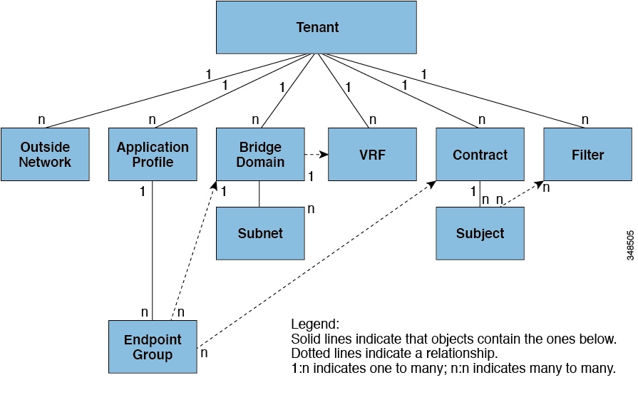

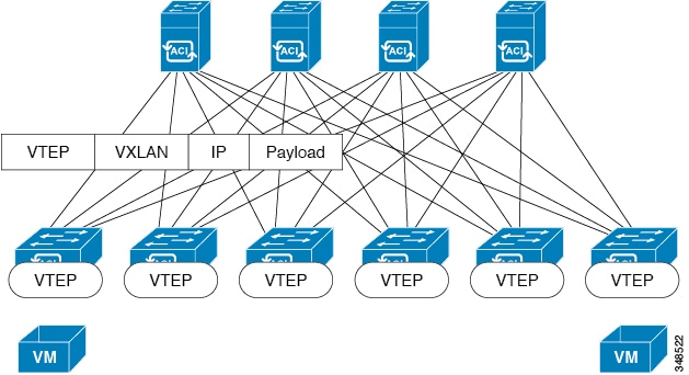
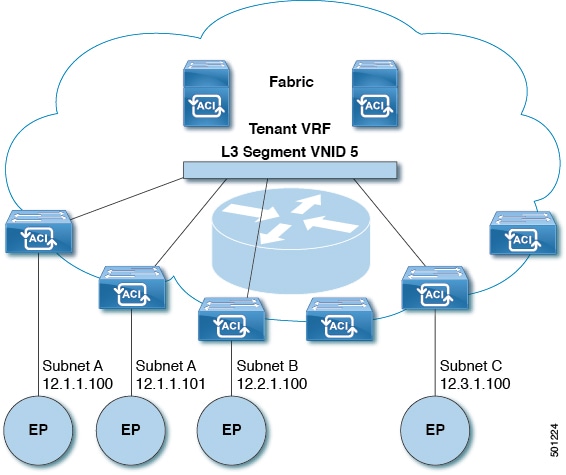
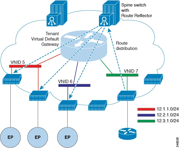
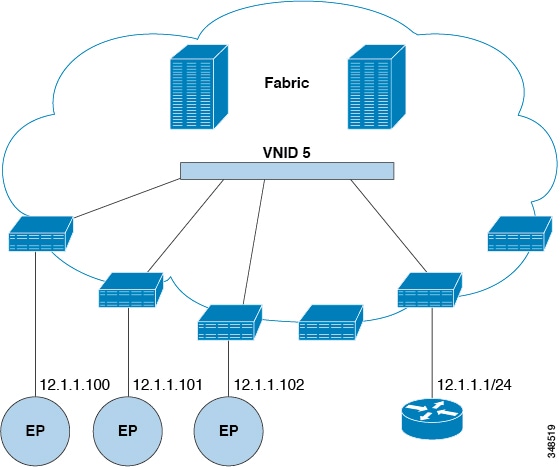
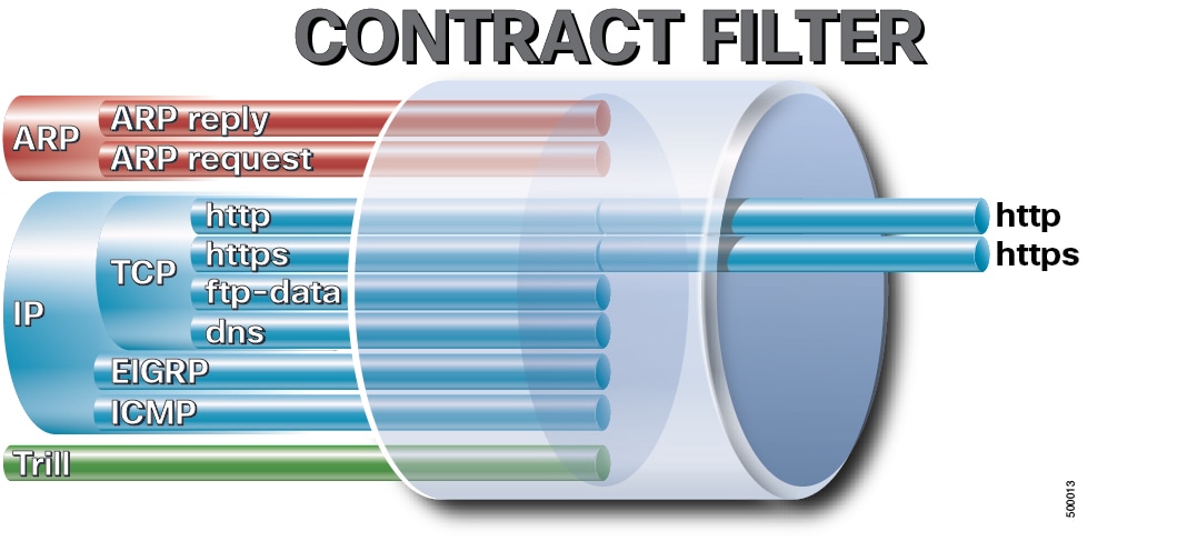
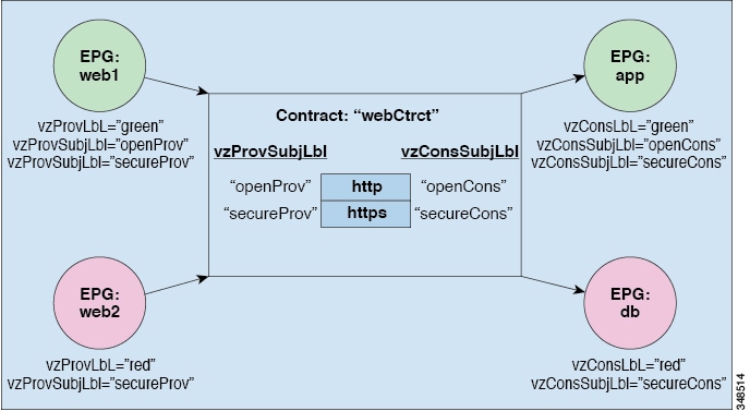
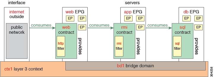
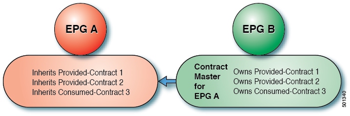

 Feedback