Configuring Policy-Based Redirect

About Policy-Based Redirect

Cisco Application Centric Infrastructure (ACI) policy-based redirect (PBR) enables provisioning service appliances, such as firewalls or load balancers, as managed or unmanaged nodes without needing a Layer 4 to Layer 7 package. Typical use cases include provisioning service appliances that can be pooled, tailored to application profiles, scaled easily, and have reduced exposure to service outages. PBR simplifies the deployment of service appliances by enabling the provisioning consumer and provider endpoint groups to be all in the same virtual routing and forwarding (VRF) instance. PBR deployment consists of configuring a route redirect policy and a cluster redirect policy, and creating a service graph template that uses the route and cluster redirect policies. After the service graph template is deployed, use the service appliance by enabling endpoint groups to consume the service graph provider endpoint group. This can be further simplified and automated by using vzAny. While performance requirements may dictate provisioning dedicated service appliances, virtual service appliances can also be deployed easily using PBR.

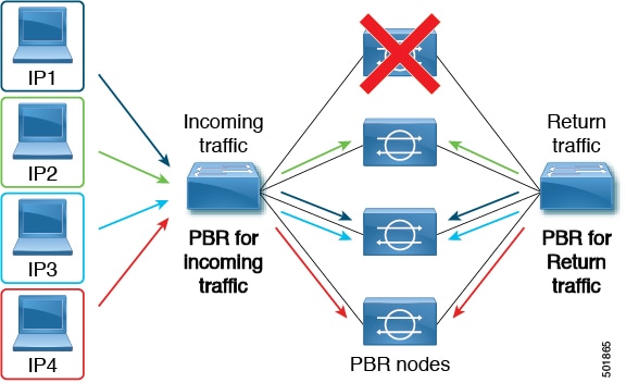
The following figure illustrates the use case of redirecting specific traffic to the firewall:

Figure 1. Use Case: Redirecting Specific Traffic to the Firewall


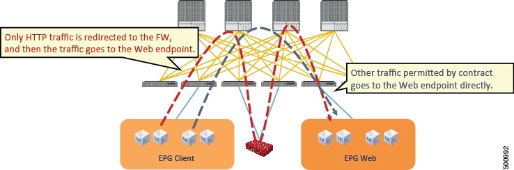
In this use case, you must create two subjects. The first subject permits HTTP traffic, which then gets redirected to the firewall. After the traffic passes through the firewall, it goes to the Web endpoint. The second subject permits all traffic, which captures traffic that is not redirected by the first subject. This traffic goes directly to the Web endpoint.

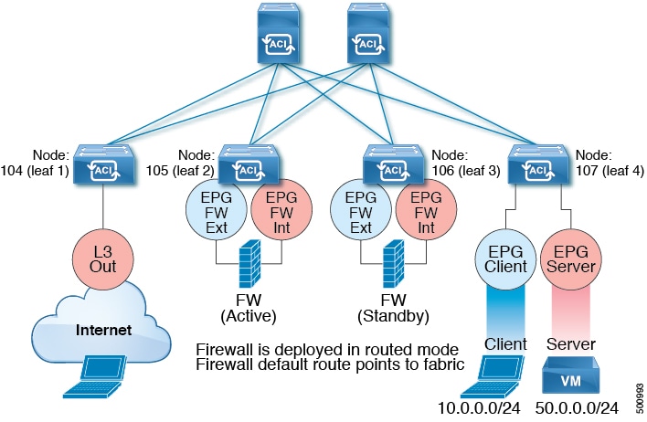
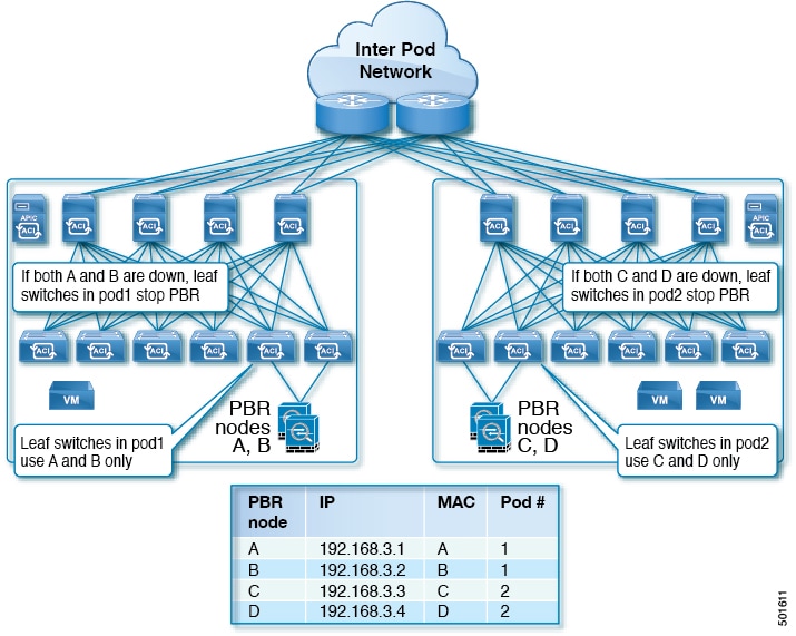
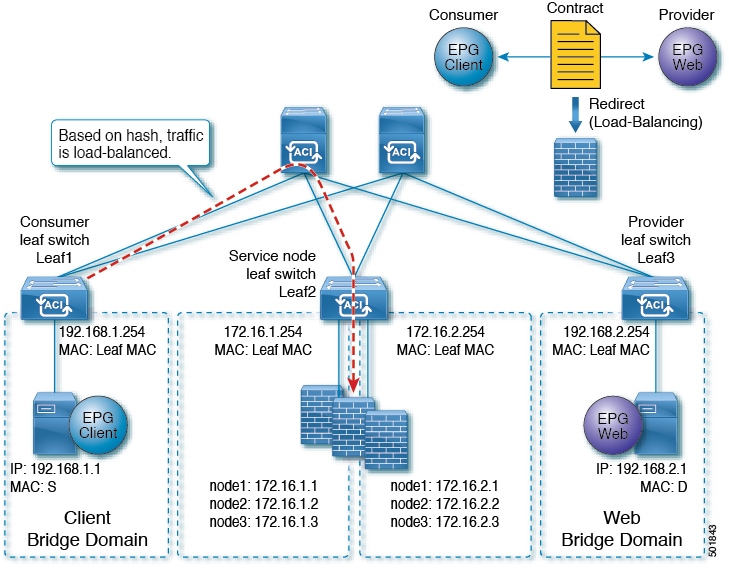
The following figure illustrates a sample ACI PBR physical topology:

Figure 2. Sample ACI PBR Physical Topology


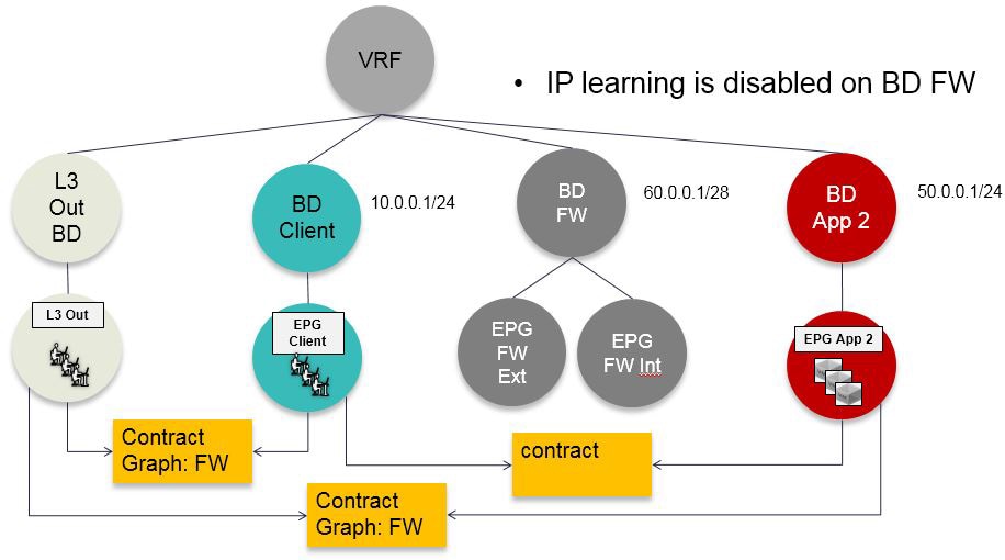
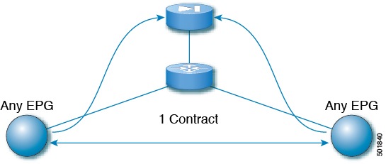
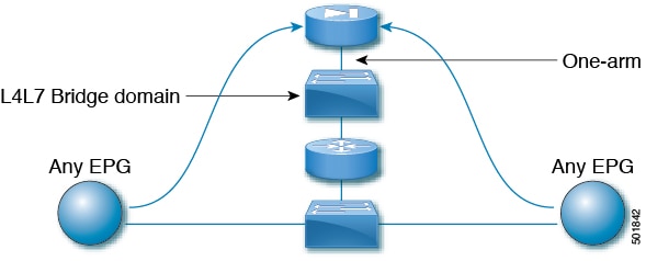
The following figure illustrates a sample ACI PBR logical topology:

Figure 3. Sample ACI PBR Logical Topology


While these examples illustrate simple deployments, ACI PBR enables scaling up mixtures of both physical and virtual service appliances for multiple services, such as firewalls and server load balancers.

Guidelines and Limitations for Configuring Policy-Based Redirect

Observe the following guidelines and limitations when planning policy-based redirect (PBR) service nodes:

  • The source MAC address of the packet can be rewritten because of the need to route the packet with PBR inside the fabric. The time-to-live (TTL) field in the IP address header will be decremented by as many times as the packet is routed within the fabric.

  • Select the same action for both service legs. In other words, if you select the deny action for the internal service leg, you should also select the deny action for the external service leg.

  • L3Out EPGs and regular EPGs can be consumer or provider EPGs.

  • For a Cold Standby active/standby deployment, configure the service nodes with the MAC address of the active deployment. In a Cold Standby active/standby deployment, when the active node goes down, the standby node takes over the MAC address of active node.

  • The next-hop service node IP address and virtual MAC address must be provided.

  • Provision service appliances in a separate bridge domain. Starting with the Cisco Application Policy Infrastructure Controller (Cisco APIC) release 3.1(x), it is not mandatory to provision service appliances in a separate bridge domain. To support this, Cisco Nexus 9300-EX and 9300-FX platform leaf switches are required.

  • When downgrading from the Cisco APIC release 3.1 software, an internal code checks whether the policy-based redirect bridge domain uses the same bridge domain as a consumer or a provider. If it does, then the fault is disabled during the downgrade as such a configuration is not supported in earlier Cisco APIC versions.

  • The service appliance, source, and bridge domain can be in the same VRF.

  • For Cisco N9K-93128TX, N9K-9396PX, N9K-9396TX, N9K-9372PX, and N9K-9372TX switches, the service appliance must not be in the same leaf switch as either the source or destination endpoint group. For Cisco N9K-C93180YC-EX and N9K-93108TC-EX switches, the service appliance can be in the same leaf switch as either the source or destination endpoint group.

  • PBR node interfaces are not supported on FEX host interfaces. A PBR node interface must be connected under leaf down link interface, not under FEX host interface. Consumer and Provider endpoints can be connected under FEX host interfaces.

  • The service appliance can only be in a bridge domain.

  • The contract offered by the service appliance provider endpoint group can be configured to allow-all, but traffic should be routed by the Cisco Application Centric Infrastructure (Cisco ACI) fabric.

  • Starting with Cisco APIC release 3.1(1), if you use the Cisco Nexus 9300-EX and 9300-FX platform leaf switches, it is not necessary for you to have the endpoint dataplane learning disabled on policy-based redirect bridge domains. During service graph deployment, the endpoint dataplane learning will be automatically disabled only for policy-based redirect node EPG. If you use non-EX and non-FX platform leaf switches, you must have the endpoint dataplane learning disabled on policy-based redirect bridge domains. The policy-based redirect bridge domain must have the endpoint dataplane learning disabled.

  • Starting from Cisco APIC release 4.2(3), filters-from-contract option is available in the Service Graph template to use the specific filter of the contract subject where the service graph is attached, instead of the default filter for zoning-rules that don't include consumer EPG class ID as source or destination. For zoning-rules that have consumer EPG class ID as source or destination, it uses the specific filter regardless the option.

  • Multi-node policy-based redirect (multi-node PBR):

    • Supports up to three function nodes in a service graph that can be configured for policy-based redirect.

    • When using a multi-node PBR service chain, all the service devices have to be either in local leaf or they have to be connected to a remote leaf, but should not spread across both.

      • Supported topoloy:

        In this topology RL means remote leaf and LL means local leaf that is under main location, and not under remote leaf.

        • N1(LL)--N2(LL)--N3(LL) - All the devices are connected to local leafs not distributed across main location and remote leaf.

        • N1(RL)-N2(RL)--N3(RL) - All the devices are connected to remote leafs.

      • Topology not supported:

        • N1(LL)--N2(RL)--N3(LL) - Service devices are distributed across LL and RL.

    • Multi-node PBR Layer 3 destination guidelines for load balancers:

      • Layer 3 destination upgrade: The Layer 3 destination (VIP) parameter is enabled by default after the upgrade. No issues will occur from this because if the PBR policy was not configured on a specific service node (pre-3.2(1)), the node connector was treated as an Layer 3 destination and will continue to be in the new Cisco APIC version.

      • Traffic does not always need to be destined to only consumer/provider

      • In the forward direction, the traffic is destined to load balancer VIP

      • In the reverse direction, if SNAT is enabled, the traffic is destined to the load balancer’s internal leg

      • In both directions, enable (check) Layer 3 destination (VIP) on the Logical Interface Context

      • Enable (check) Layer 3 destination (VIP) in both directions to allow you to switch from SNAT to No-SNAT on the load balancer internal by configuring the PBR policy on the internal side

      • If SNAT is disabled:

        • Reverse direction traffic is destined to consumer but not to load balancer internal leg (enable PBR policy on the internal leg)

        • Layer 3 destination (VIP) is not applicable in this case because a PBR policy is applied

  • Multicast and broadcast traffic redirection is not supported.

  • Starting from Cisco APIC release 4.1, with L1/L2 PBR support the redirection to transparent services is supported.

  • If you change a redirect policy's destination to a different group, the Cisco APIC raises a fault due to the change and the policy's operational status becomes disabled. You must clear the fault to re-enable the policy.

  • Supported policy-based redirect configurations in the same VRF instance include the following:

    Figure 4. Supported Policy-based Redirect Configurations in the Same VRF Instance
  • Supported policy-based redirect configurations in a different VRF instance include the following:

    Figure 5. Supported Policy-based Redirect Configurations in a Different VRF Instance
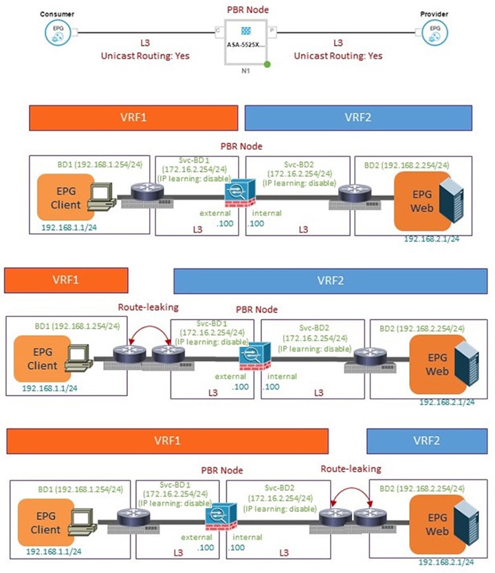
  • Unsupported policy-based redirect configurations include the following:

    Figure 6. Unsupported Policy-based Redirect Configurations


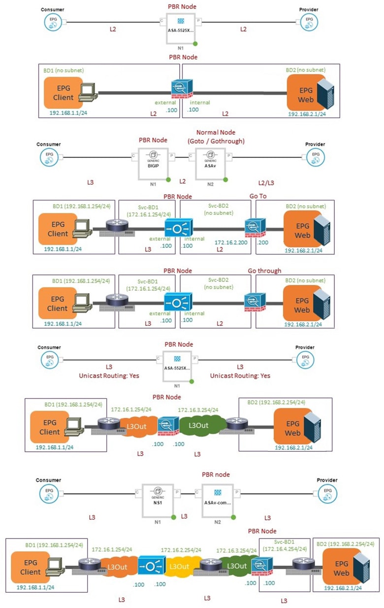
Configuring Policy-Based Redirect Using the GUI

The following procedure configures policy-based redirect (PBR) using the GUI.


Note

The policy-based redirect feature is referred to as "policy-based routing" in the GUI.


Procedure


Step 1

On the menu bar, choose Tenants > All Tenants.

Step 2

In the Work pane, double click the tenant's name.

Step 3

In the Navigation pane, choose Tenant tenant_name > Services > L4-L7 > Devices.

Step 4

In the Work pane, choose Actions > Create L4-L7 Devices.

Step 5

In the Create L4-L7 Devices dialog box, complete the fields as required.

In the General section, the Service Type can be Firewall or ADC.

Note 

For L1/L2 PBR configuration, create the L4-L7 device in Unmanaged mode, and perform the following steps:

  1. Select the Service Type as Other.

  2. Select the Device Type Physical (cloud/virtual is not supported).

  3. Select a physical domain.

  4. Select the Function Type L1 or L2 as required.

  5. Create external and internal concrete interfaces and port connectivity on the corresponding leafs.

  6. Create Cluster interfaces by selecting the previously created concrete interfaces (leave VLAN encapsulation blank for dynamic assignments).

    Note 

    For static VLAN configuration, ensure external and internal legs have a different VLAN for L2, otherwise it is the same VLAN for L1.

Step 6

In the Navigation pane, choose Tenant tenant_name > Services > L4-L7 > Service Graph Templates.

Step 7

In the Work pane, choose Action > Create L4-L7 Service Graph Template.

Step 8

In the Create L4-L7 Service Graph Template dialog box, perform the following actions:

  1. In the Graph Name field, enter a name for the service graph template.

  2. For the Graph Type radio buttons, click Create A New Graph.

  3. Drag and drop the device that you created from the Device Clusters pane to between the consumer endpoint group and provider endpoint group. This creates the service node.

    As of APIC Release 4.2(1), you can optionally repeat step c to include up to five (5) service node devices supporting PBR.

  4. Select the following based on the service type of the device:

    For Firewall, select Routed and continue with the steps below. For ADC, select One-Arm or Two-Arm and continue with the steps below.
  5. In the Profile drop-down list, select a function profile appropriate to the device. If no profiles exist, create one by following the instruction in the Creating a Function Profile Using the GUI.

  6. Select the Route Redirect checkbox.

  7. Click Submit.

The new service graph template appears in the Service Graph Templates table.
Step 9

In the Navigation pane, choose Tenant tenant_name > Policies > Protocol > L4-L7 Policy Based Redirect.

Step 10

In the Work pane, choose Action > Create L4-L7 Policy Based Redirect.

Step 11

In the Create L4-L7 Policy Based Redirect dialog box, complete the fields as required. This policy-based redirect policy is for the consumer connector.

Step 12

Create another policy-based redirect policy for the provider connector.

Step 13

In the Navigation pane, choose Tenant tenant_name > Services > L4-L7 > Service Graph Templates > service_graph_template_name .

Choose the service graph template that you just created.

Step 14

Right click the service graph template and choose Apply L4-L7 Service Graph Template.

Step 15

In the Apply L4-L7 Service Graph Template to EPGs dialog box, perform the following actions:

  1. In the Consumer EPG/External Network drop-down list, choose the consumer endpoint group.

  2. In the Provider EPG/External Network drop-down list, choose the provider endpoint group.

  3. For the Contract radio buttons, click Create A New Contract.

  4. In the Contract Name field, enter a name for the contract.

  5. Do not put a check in the No Filter (Allow All Traffic) check box.

  6. On the Filter Entries table, click + to add an entry.

  7. For the new filter entry, enter "IP" for the name, choose IP for the Ether Type, and click Update.

  8. Click Next.

  9. For the Consumer Connector BD drop-down list, choose the external bridge domain that connects to the consumer endpoint group. Select No for IP Data-plane Learning.

  10. For the Consumer Connector Redirect Policy drop-down list, choose the redirect policy that you created for the consumer connector.

  11. For the Consumer Connector Cluster Interface drop-down list, choose the consumer cluster interface.

  12. For the Provider Connector BD drop-down list, choose the internal bridge domain that connects to the provider endpoint group. Select No for IP Data-plane Learning.

  13. For the Provider Connector Redirect Policy drop-down list, choose the redirect policy that you created for the provider connector.

  14. For the Provider Connector Cluster Interface drop-down list, choose the provider cluster interface.

  15. Click Next.

  16. Configure the parameters as necessary for the device.

  17. Cick Finish.


Configuring Policy-Based Redirect Using the NX-OS-Style CLI

The example commands in this procedure include the route redirect, the cluster redirect, and the graph deployment. The device is created under tenant T1. The device is a Cisco ASA virtual device in managed mode; only unmanaged mode devices can be configured using the CLI.

Procedure


Step 1

Create the device cluster.

Example:

  l4l7 cluster name ifav-asa-vm-ha type virtual vlan-domain ACIVswitch service FW function go-to
      cluster-device Device2 vcenter ifav108-vcenter vm "ASAv_HA1"
      cluster-device Device1 vcenter ifav108-vcenter vm "ASAv_HA"
      cluster-interface provider
        member device Device1 device-interface GigabitEthernet0/1
          interface ethernet 1/45 leaf 102
          vnic "Network adapter 3"
          exit
        member device Device2 device-interface GigabitEthernet0/1
          interface ethernet 1/45 leaf 102
          vnic "Network adapter 3"
          exit
        exit
      cluster-interface failover_link
        member device Device1 device-interface GigabitEthernet0/8
          interface ethernet 1/45 leaf 102
          vnic "Network adapter 10"
          exit
        member device Device2 device-interface GigabitEthernet0/8
          interface ethernet 1/45 leaf 102
          vnic "Network adapter 10"
          exit
        exit
      cluster-interface consumer
        member device Device1 device-interface GigabitEthernet0/0
          interface ethernet 1/45 leaf 102
          vnic "Network adapter 2"
          exit
        member device Device2 device-interface GigabitEthernet0/0
          interface ethernet 1/45 leaf 102
          vnic "Network adapter 2"
          exit
        exit
      exit
  exit 
Step 2

Under tenant PBRv6_ASA_HA_Mode, deploy the PBR service graph instance.

Example:

  tenant PBRv6_ASA_HA_Mode
    access-list Contract_PBRv6_ASA_HA_Mode_Filter
      match ip
      exit
Step 3

Create a contract for PBR with the filter match IP protocol. Under the subject, specify the Layer 4 to Layer 7 service graph name.

The contract offered by the service appliance provider endpoint group cannot be configured with the allow-all setting.

Example:

    contract Contract_PBRv6_ASA_HA_Mode
      scope tenant
      subject Subject
        access-group Contract_PBRv6_ASA_HA_Mode_Filter both  
        l4l7 graph PBRv6_ASA_HA_Mode_Graph
        exit
      exit
    vrf context CTX1
      exit
    vrf context CTX2
      exit
Step 4

Create a bridge domain for the client and server endpoint group. Both the client and server are in the same VRF instance.

Example:

    bridge-domain BD1
      arp flooding
      l2-unknown-unicast flood
      vrf member CTX1
      exit
    bridge-domain BD2
      arp flooding
      l2-unknown-unicast flood
      vrf member CTX1
      exit
Step 5

Create a separate bridge domain for the external and internal leg of the firewall.

PBR requires the learning of the source VTEP on remote leaf switches to be disabled, which is done using the no ip learning command.

Example:

    bridge-domain External-BD3
      arp flooding
      no ip learning
      l2-unknown-unicast flood
      vrf member CTX1
      exit
    bridge-domain Internal-BD4
      arp flooding
      no ip learning
      l2-unknown-unicast flood
      vrf member CTX1
      exit
Step 6

Create the application profile and specify the endpoint groups.

Example:

    application AP1
      epg ClientEPG
        bridge-domain member BD1
        contract consumer Contract_PBRv6_ASA_HA_Mode
        exit
      epg ServerEPG
        bridge-domain member BD2
        contract provider Contract_PBRv6_ASA_HA_Mode
        exit
      exit
Step 7

Specify the default gateway for the bridge domains.

Example:

    interface bridge-domain BD1
      ipv6 address 89:1:1:1::64/64
      exit
    interface bridge-domain BD2
      ipv6 address 99:1:1:1::64/64
      exit

	interface bridge-domain External-BD3
      ipv6 address 10:1:1:1::64/64
      exit
    interface bridge-domain Internal-BD4
      ipv6 address 20:1:1:1::64/64
      exit
Step 8

Import the device from tenant T1.

Example:

l4l7 cluster import-from T1 device-cluster ifav-asa-vm-ha
Step 9

Create the service graph using the service redirect policy.

Example:

l4l7 graph PBRv6_ASA_HA_Mode_Graph contract Contract_PBRv6_ASA_HA_Mode
      service N2 device-cluster-tenant T1 device-cluster ifav-asa-vm-ha mode FW_ROUTED svcredir enable
      connector consumer cluster-interface consumer_PBRv6
          bridge-domain tenant PBRv6_ASA_HA_Mode name External-BD3
          svcredir-pol tenant PBRv6_ASA_HA_Mode name External_leg
          exit
      connector provider cluster-interface provider_PBRv6
          bridge-domain tenant PBRv6_ASA_HA_Mode name Internal-BD4
          svcredir-pol tenant PBRv6_ASA_HA_Mode name Internal_leg
          exit
        exit
    connection C1 terminal consumer service N2 connector consumer
    connection C2 terminal provider service N2 connector provider
    exit
Step 10

Create the service redirect policy for the external and internal legs. IPv6 addresses are used in this example; you can also specify IPv4 addresses using the same command.

Example:

svcredir-pol Internal_leg
    redir-dest 20:1:1:1::1 00:00:AB:CD:00:11
    exit
svcredir-pol External_leg
    redir-dest 10:1:1:1::1 00:00:AB:CD:00:09
    exit
exit

Verifying a Policy-Based Redirect Configuration Using the NX-OS-Style CLI

After you have configured policy-based redirect, you can verify the configuration using the NX-OS-style CLI.

Procedure


Step 1

Show the running configuration of the tenant.

Example:

apic1# show running-config tenant PBRv6_ASA_HA_Mode svcredir-pol
# Command: show running-config tenant PBRv6_ASA_HA_Mode svcredir-pol
# Time: Wed May 25 00:57:22 2016
  tenant PBRv6_ASA_HA_Mode
    svcredir-pol Internal_leg
      redir-dest 20:1:1:1::1/32 00:00:AB:CD:00:11
      exit
    svcredir-pol External_leg
      redir-dest 10:1:1:1::1/32 00:00:AB:CD:00:09
      exit
    exit
Step 2

Show the running configuration of the tenant and its service graph.

Example:

apic1# show running-config tenant PBRv6_ASA_HA_Mode l4l7 graph PBRv6_ASA_HA_Mode_Graph
# Command: show running-config tenant PBRv6_ASA_HA_Mode l4l7 graph PBRv6_ASA_HA_Mode_Graph     
# Time: Wed May 25 00:55:09 2016                                                               
  tenant PBRv6_ASA_HA_Mode                                                                     
    l4l7 graph PBRv6_ASA_HA_Mode_Graph contract Contract_PBRv6_ASA_HA_Mode                     
      service N2 device-cluster-tenant T1 device-cluster ifav-asa-vm-ha mode FW_ROUTED svcredir enable
        connector consumer cluster-interface consumer_PBRv6                                           
          bridge-domain tenant PBRv6_ASA_HA_Mode name External-BD3                                    
          svcredir-pol tenant PBRv6_ASA_HA_Mode name External_leg                                     
          exit                                                                                        
        connector provider cluster-interface provider_PBRv6                                           
          bridge-domain tenant PBRv6_ASA_HA_Mode name Internal-BD4
          svcredir-pol tenant PBRv6_ASA_HA_Mode name Internal_leg
          exit
        exit
      connection C1 terminal consumer service N2 connector consumer
      connection C2 terminal provider service N2 connector provider
      exit
    exit
Step 3

Show the service graph configuration.

Example:

apic1# show l4l7-graph graph PBRv6_ASA_HA_Mode_Graph
Graph           : PBRv6_ASA_HA_Mode-PBRv6_ASA_HA_Mode_Graph
Graph Instances : 1

Consumer EPg     : PBRv6_ASA_HA_Mode-ClientEPG
Provider EPg     : PBRv6_ASA_HA_Mode-ServerEPG
Contract Name    : PBRv6_ASA_HA_Mode-Contract_PBRv6_ASA_HA_Mode
Config status    : applied
Service Redirect : enabled

Function Node Name : N2
 Connector   Encap       Bridge-Domain  Device Interface      Service Redirect Policy
 ----------  ----------  ----------     --------------------  -----------------------
 consumer    vlan-241    PBRv6_ASA_HA_  consumer_PBRv6        External_leg
                         Mode-
                         External-BD3
 provider    vlan-105    PBRv6_ASA_HA_  provider_PBRv6        Internal_leg
                         Mode-
                         Internal-BD4

About Multi-Node Policy-Based Redirect

Multi-node policy-based redirect enhances PBR by supporting up to five nodes in a single service graph. You can configure which service node connector terminates the traffic and based on this configuration, the source and destination class IDs for the service chain are determined. In the multi-node PBR feature, policy-based redirection can be enabled on the consumer, provider, or both of the service node connectors. It can also be configured for the forward or reverse directions. If the PBR policy is configured on a service node connector, then that connector does not terminate traffic.

About Symmetric Policy-Based Redirect

Symmetric policy-based redirect (PBR) configurations enable provisioning a pool of service appliances so that the consumer and provider endpoint groups traffic is policy-based. The traffic is redirected to one of the service nodes in the pool, depending on the source and destination IP equal-cost multi-path routing (ECMP) prefix hashing.


Note

Symmetric PBR configurations require 9300-EX hardware.

Sample symmetric PBR REST posts are listed below:

Under fvTenant svcCont

<vnsSvcRedirectPol name=“LoadBalancer_pool”>
          <vnsRedirectDest name=“lb1” ip=“1.1.1.1” mac=“00:00:11:22:33:44”/> 
          <vnsRedirectDest name=“lb2” ip=“2.2.2.2” mac=“00:de:ad:be:ef:01”/> 
          <vnsRedirectDest name=“lb3” ip=“3.3.3.3” mac=“00:de:ad:be:ef:02”/> 
</vnsSvcRedirectPol>

<vnsLIfCtx name=“external”> 
          <vnsRsSvcRedirectPol tnVnsSvcRedirectPolName=“LoadBalancer_pool”/> 
          <vnsRsLIfCtxToBD tDn=“uni/tn-solar/bd-fwBD”>
</vnsLIfCtx>

<vnsAbsNode name=“FW” routingMode=“redirect”>

Sample symmetric PBR NX-OS-style CLI commands are listed below.

The following commands under the tenant scope create a service redirect policy:

apic1(config-tenant)# svcredir-pol fw-external
apic1(svcredir-pol)# redir-dest 2.2.2.2 00:11:22:33:44:56

The following commands enable PBR:

apic1(config-tenant)# l4l7 graph FWOnly contract default
apic1(config-graph)# service FW svcredir enable

The following commands set the redirect policy under the device selection policy connector:

apic1(config-service)# connector external
apic1(config-connector)# svcredir-pol tenant solar name fw-external

Policy Based Redirect and Hashing Algorithms


Note

This feature is available in the APIC Release 2.2(3x) release and going forward with APIC Release 3.1(1). It is not supported in APIC Release 3.0(x).


In Cisco APIC, Release 2.2(3x), Policy Based Redirect feature (PBR) supports the following hashing algorithms:

  • Source IP address

  • Destination IP address

  • Source IP address, Destination IP address, and Protocol number (default configuration).

Policy-Based Redirect Resilient Hashing

In symmetric PBR, incoming and return user traffic uses the same PBR node in an ECMP group. If, however, one of the PBR nodes goes down/fails, the existing traffic flows are rehashed to another node. This can cause issues such as existing traffic on the functioning node being load balanced to other PBR nodes that do not have current connection information. If the traffic is traversing a stateful firewall, it can also lead to the connection being reset.

Resilient hashing is the process of mapping traffic flows to physical nodes and avoiding the rehashing of any traffic other than the flows from the failed node. The traffic from the failed node is remapped to a "backup" node. The existing traffic on the "backup" node is not moved.

The image below shows the basic functionality of symmetric PBR with incoming and return user traffic using the same PBR nodes.

Figure 7. Symmetric PBR

The next image shows what occurs when one of the PBR nodes is disabled or fails. The traffic for IP1 is rehashed to the next node and IP2 and IP3's traffic is load balanced to another PBR node. As stated earlier, this could lead to connectivity interruptions or delays if the other PBR nodes do not have the current connection information for IP2 and IP3 traffic.

Figure 8. Disabled/Failed PBR node without resilient hashing

The final image shows how this same use case is addressed when resilient hashing is enabled. Only the user traffic from the disabled/failed node is moved. All other user traffic remains on their respective PBR nodes.

Figure 9. Disabled/Failed PBR node with resilient hashing

If the node returns to service, the traffic flows rehashed from the failed node to the active node are returned to the reactivated node.


Note

Adding or deleting PBR nodes from the ECMP group can cause all the traffic flows to be rehashed.


Enabling Resilient Hashing in L4-L7 Policy-Based Redirect

Before you begin

This task assumes that an L4-L7 Policy Based Redirect policy has been created.

Procedure


Step 1

On the menu bar, choose Tenants > All Tenants.

Step 2

In the Work pane, double-click the tenant's name.

Step 3

In the Navigation pane, choose Tenant tenant_name > Policies > Protocol > L4-L7 Policy Based Redirect > L4-L7_PBR_policy_name .

Step 4

In the Work pane, check the Resilient Hashing Enabled check box.

Step 5

Click Submit.


PBR Support for Service Nodes in Consumer and Provider Bridge Domains

Starting with the Cisco APIC 3.1(1) release, bridge domains (BDs) that contain a consumer or provider also support service nodes. Therefore, you are not required to provision separate PBR bridge domains any longer.

The Cisco Nexus 9300-EX and 9300-FX platform leaf switches support this feature.

Policy-Based Redirect and Tracking Service Nodes

Beginning with the Cisco Application Policy Infrastructure Controller (APIC) 2.2(3) and 3.1(1) releases (but, excluding the 3.0 releases), the policy-based redirect feature (PBR) supports the ability to track service nodes. Tracking enables you to prevent redirection of traffic to a service node that is down. If a service node (PBR destination) is down, the PBR hashing can begin selecting an available PBR destination in a policy. This feature requires Cisco Nexus 9300-EX, -FX, or later platform leaf switches.

Service nodes can support dual IP address stacking. Therefore, this feature has the capability to track both IPv4 and IPv6 addresses at the same time. When both IPv4 and IPv6 addresses are "up," the PBR destination is marked as "up."

Switches internally use the Cisco IP SLA monitoring feature to support PBR tracking. The tracking feature marks a redirect destination node as "down" if the service node is not reachable. The tracking feature marks a redirect destination as node "up" if the service node resumes connectivity. When a service node is marked as "down," it will not be used to send or hash the traffic. Instead, the traffic will be sent or hashed to a different service node in the cluster of redirection destination nodes.

To avoid black holing of the traffic in one direction, you can associate a service node's ingress and egress redirect destination nodes with a redirection health policy. Doing so ensures that if either an ingress or egress redirection destination node is down, the other redirection destination node will also be marked as "down." Hence, both ingress and egress traffic gets hashed to a different service node in the cluster of the redirect destination nodes.

You can use the following protocols for tracking:

  • ICMP (for Layer 3 PBR)

  • TCP (for Layer 3 PBR)

  • L2ping (for Layer 1/2 PBR)

Policy-Based Redirect and Threshold Settings for Tracking Service Nodes

The following threshold settings are available when configuring a policy-based redirect (PBR) policy for tracking service nodes:

  • Threshold enabled or disabled: When the threshold is enabled, you an specify the minimum and maximum threshold percentages. Threshold enabled is required when you want to disable the redirect destination group completely and prevent any redirection. When there is no redirection, the traffic is directly sent between the consumer and the provider.

  • Minimum threshold: The minimum threshold percentage specified. If the traffic goes below the minimum percentage, the packet is permitted instead of being redirected. The default value is 0.

  • Maximum threshold: The maximum threshold percentage specified. Once the minimum threshold is reached, to get back to operational state, the maximum percentage must first be reached. The default value is 0.

Let us assume as an example that there are three redirect destinations in a policy. The minimum threshold is specified at 70% and the maximum threshold is specified at 80%. If one of the three redirect destination policies goes down, the percentage of availability goes down by one of three (or 33%), which is less than the minimum threshold. As a result, the minimum threshold percentage of the redirect destination group is brought down and traffic begins to get permitted instead of being redirected. Continuing with the same example, if the maximum threshold is 80%, to bring the redirect policy destination group back to the operational state, a percentage greater than the maximum threshold percentage must be reached.

Guidelines and Limitations for Policy-Based Redirect Tracking With Service Nodes

Follow these guidelines and limitations when using policy-based redirect (PBR) tracking with service nodes:

  • A Cisco ACI Multi-Pod fabric setup is supported.

  • A Cisco ACI Multi-Site setup is not supported.

  • An L3Out is supported for the consumer and provider EPGs.

  • TCP or ICMP protocol types are used to track the redirect destination nodes.

  • PBR supports up to 100 trackable IP addresses in leaf switches and 200 trackable IP addresses in the Cisco Application Centric Infrastructure (ACI) fabric.

  • PBR supports up to 1,000 service graph instances per Cisco ACI fabric.

  • PBR supports up to 100 service graph instances per device.

  • You can configure up to 40 service nodes per PBR policy.

  • You can configure up to 3 service nodes per service chain.

  • Shared services are supported with PBR tracking.

  • The following threshold down actions are supported:

    • deny action

    • permit action

  • If multiple PBR policies have the same PBR destination IP address in the same VRF instance, the policies must use the same IP SLA policy and health group for the PBR destination.

Configuring PBR and Tracking Service Nodes Using the GUI

Procedure


Step 1

On the menu bar, click Tenant > tenant_name. In the navigation pane, click Policies > Protocol > L4-L7 Policy Based Redirect .

Step 2

Right-click L4 –L7 Policy Based Redirect, and click Create L4–L7 Policy Based Redirect.

Step 3

In the Create L4–L7 Policy Based Redirect dialog box, perform the following actions:

  1. In the Name field, enter a name for the PBR policy.

  2. In the dialog box, choose the appropriate settings to configure the hashing algorithm, IP SLA Monitoring Policy, and other required values.

    Note 

    Destination groups that share destinations must have same IP SLA monitoring policy configured.

  3. In the threshold setting fields, specify the settings as appropriate and if desired.

  4. Expand Destinations to display Create Destination of Redirected Traffic.

  5. In the Create Destination of Redirected Traffic dialog box, enter the appropriate details including the IP address and the MAC address fields.

    The fields for IP address and Second IP address are provided where you can specify IPv4 and/or IPv6 addresses.

    Note 

    This field is not mandatory. Use it if the L4-L7 device has multiple IP addresses and you want ACI to verify both of them.

    If both the IP and Second IP parameters are configured, both must be up in order to mark the PBR destination as "UP".

  6. In the Redirect Health Group field, associate an existing health group or create a new health group, as appropriate. Click OK.

    Note 

    Destination groups that share destinations must have same health group configured.

  7. In the Create L4–L7 Policy Based Redirect dialog box, click Submit.

The L4-L7 Policy Based Redirect and tracking of service nodes is configured after binding the redirect health group policy to the L4-L7 PBR policy and the settings to track the redirect destination group are enabled.

Configuring a Redirect Health Group Using the GUI

Procedure


Step 1

On the menu bar, click Tenant > tenant_name. In the navigation pane, click Policies > Protocol > L4-L7 Redirect Health Groups.

Step 2

Right-click L4 –L7 Redirect Health Groups, and choose Create L4–L7 Redirect Health Group.

Step 3

In the Create L4–L7 Redirect Health Group dialog box, perform the following actions:

  1. In the Name field, enter a name for the Redirect Health Group policy.

  2. In the Description field, enter additional information if appropriate, and click Submit.

The Layer 4 to Layer 7 services redirect health policy is configured.

Configuring PBR to Support Tracking Service Nodes Using the REST API

Procedure


Configure PBR to support tracking service nodes.

Example:

<polUni>
    <fvTenant name="t1" >
    <fvIPSLAMonitoringPol name="tcp_Freq60_Pol1" slaType="tcp" slaFrequency="60" slaPort="2222" />
    <vnsSvcCont>
        <vnsRedirectHealthGroup name="fwService1"/>
          <vnsSvcRedirectPol name="fwExt" hashingAlgorithm="sip" thresholdEnable="yes"
            minThresholdPercent="20" maxThresholdPercent="80">
            <vnsRedirectDest ip="40.40.40.100" mac="00:00:00:00:00:01">
               <vnsRsRedirectHealthGroup tDn="uni/tn-t1/svcCont/redirectHealthGroup-fwService1"/>
            </vnsRedirectDest>
            <vnsRsIPSLAMonitoringPol tDn="uni/tn-t1/ipslaMonitoringPol-tcp_Freq60_Pol1"/>
          </vnsSvcRedirectPol>
         <vnsSvcRedirectPol name="fwInt" hashingAlgorithm="sip" thresholdEnable="yes"
           minThresholdPercent="20" maxThresholdPercent="80">
             <vnsRedirectDest ip="30.30.30.100" mac="00:00:00:00:00:02">
                <vnsRsRedirectHealthGroup tDn="uni/tn-t1/svcCont/redirectHealthGroup-fwService1"/>
             </vnsRedirectDest>
             <vnsRsIPSLAMonitoringPol tDn="uni/tn-t1/ipslaMonitoringPol-tcp_Freq60_Pol1"/>
          </vnsSvcRedirectPol>
        </vnsSvcCont>
    </fvTenant>
</polUni>

About Location-Aware Policy Based Redirect

Location-Aware Policy Based Redirect (PBR) is now supported. This feature is useful in a multipod configuration scenario. Now there is pod-awareness support, and you can specify the preferred local PBR node. When you enable location-aware redirection, and Pod IDs are specified, all the redirect destinations in the Layer 4-Layer 7 PBR policy will have pod awareness. The redirect destination is programmed only in the leaf switches located in a specific pod.

The following image displays an example with two pods. PBR nodes A and B are in Pod 1 and PBR nodes C and D are in Pod 2. When you enable the location-aware PBR configuration, the leaf switches in Pod 1 prefer to use PBR nodes A and B, and the leaf switches in Pod 2 use PBR nodes in C and D. If PBR nodes A and B in Pod 1 are down, then the leaf switches in Pod 1 will start to use PBR nodes C and D. Similarly, if PBR nodes C and D in Pod 2 are down, the leaf switches in Pod 2 will start to use PBR nodes A and B.

Figure 10. An Example of Location Aware PBR Configuration with Two Pods

Guidelines for Location-Aware PBR

Follow these guidelines when using location-aware PBR:

  • The Cisco Nexus 9300 (except Cisco Nexus 9300–EX and 9300–FX) platform switches do not support the location-aware PBR feature.

  • Use location-aware PBR for north-south firewall integration with GOLF host advertisement.

    Use location-aware PBR for a contract that is enforced on the same leaf nodes for incoming and returning traffic, such as an intra-VRF contract for external-EPG-to-EPG and an inter-VRF contract for EPG-to-EPG traffic. Otherwise, there can be a loss of traffic symmetry.

  • If multiple PBR policies have the same PBR destination IP address in the same VRF, then all of the policies must either have Pod ID aware redirection enabled or Pod ID aware redirection disabled. The same (VRF, IP address) pair cannot be used in Pod ID aware redirection enabled and Pod ID aware redirection disabled policies at the same time. For example, the following configuration is not supported:

    • PBR-policy1 has PBR destination 192.168.1.1 in VRF A, Pod ID aware redirection enabled, and 192.168.1.1 is set to POD 1.

    • PBR-policy2 has PBR destination 192.168.1.1 in VRF A and Pod ID aware redirection disabled.

Configuring Location-Aware PBR Using the GUI

You must program two items for this feature to be enabled. Enable pod ID aware redirection and associate the Pod IDs with the preferred PBR nodes to program redirect destinations in the leaf switches located in the specific pods.

Procedure


Step 1

On the menu bar, click Tenant > tenant_name . In the Navigation pane, click Policies > Protocol > L4-L7 Policy Based Redirect .

Step 2

Right-click L4 –L7 Policy Based Redirect, and click Create L4–L7 Policy Based Redirect.

Step 3

In the Create L4–L7 Policy Based Redirect dialog box, perform the following actions:

  1. In the Name field, enter a name for the PBR policy.

  2. In the Enable Pod ID Aware Redirection check the check box.

  3. In the dialog box, choose the appropriate settings to configure the hashing algorithm, IP SLA Monitoring Policy, and other required values.

  4. In the threshold setting fields, specify the settings as appropriate and if desired.

  5. Expand Destinations to display Create Destination of Redirected Traffic.

  6. In the Create Destination of Redirected Traffic dialog box, enter the appropriate details including the IP address and the MAC address fields.

    The fields for IP address and Second IP address are provided where you can specify an IPv4 address and an IPv6 address.

  7. In the Pod ID field, enter the pod identification value.

  8. In the Redirect Health Group field, associate an existing health group or create a new health group, as appropriate. Click OK.

    Create additional destinations of redirected traffic with different Pod IDs as required.

  9. In the Create L4–L7 Policy Based Redirect dialog box, click Submit.

The L4-L7 location-aware PBR is configured.

Configuring Location-Aware PBR Using the REST API

You must configure two items to enable location-aware PBR and to program redirect destinations in the leaf switches located in the specific pods. The attributes that are configured to enable location-aware PBR in the following example are: programLocalPodOnly and podId.

Procedure


Configure location-aware PBR.

Example:


<polUni>
    <fvTenant name="coke" >
    <fvIPSLAMonitoringPol name="icmp_Freq60_Pol1" slaType="icmp" slaFrequency="60"/>
    <vnsSvcCont>
        <vnsRedirectHealthGroup name="fwService1"/>
          <vnsSvcRedirectPol name="fwExt" hashingAlgorithm="sip" thresholdEnable="yes" minThresholdPercent="20" maxThresholdPercent="80" programLocalPodOnly="yes">
            <vnsRedirectDest ip="40.40.40.100" mac="00:00:00:00:00:01" podId="2">
               <vnsRsRedirectHealthGroup tDn="uni/tn-coke/svcCont/redirectHealthGroup-fwService1"/>
            </vnsRedirectDest>
            <vnsRsIPSLAMonitoringPol tDn="uni/tn-coke/ipslaMonitoringPol-icmp_Freq60_Pol1"/>
          </vnsSvcRedirectPol>
          <vnsSvcRedirectPol name="fwInt" hashingAlgorithm="dip" thresholdEnable="yes" minThresholdPercent="20" maxThresholdPercent="80">
             <vnsRedirectDest ip="30.30.30.100" mac="00:00:00:00:00:02">
                <vnsRsRedirectHealthGroup tDn="uni/tn-coke/svcCont/redirectHealthGroup-fwService1"/>
             </vnsRedirectDest>
             <vnsRsIPSLAMonitoringPol tDn="uni/tn-coke/ipslaMonitoringPol-icmp_Freq60_Pol1"/>
          </vnsSvcRedirectPol>
        </vnsSvcCont>
    </fvTenant>
</polUni>

Policy-Based Redirect and Service Graphs to Redirect All EPG-to-EPG Traffic Within the Same VRF Instance

You can configure Cisco Application Centric Infrastructure (Cisco ACI) to forward all traffic from any endpoint group to any other endpoint group in the same VRF instance through a Layer 4 to Layer 7 device by configuring vzAny with service graph redirect. vzAny is a construct that represents all the endpoint groups under the same VRF instance. vzAny is sometimes referred to as "any EPG."

Figure 11. vzAny topology

Traffic between any endpoint group pair that is under the same VRF instance can be redirected to a Layer 4 to Layer 7 device, such as a firewall. You can also redirect traffic within the same bridge domain to a firewall. The firewall can filter traffic between any pair of endpoint groups, as illustrated in the following figure:

Figure 12. A firewall filtering traffic between any pair of EPGs

One use case of this functionality is to use Cisco ACI as a default gateway, but filter traffic through a firewall. With vzAny and a policy-based redirect policy, the security administrator manages the ACL rules and the network administrator manages routing and switching. Some of the benefits of this configuration include being able to use the Cisco Application Policy Infrastructure Controller's (Cisco APIC's) tools, such as endpoint tracking, first hop security with ARP inspection, or IP address source guard.

Applying a service graph with a policy-based redirect policy also enables the following functionality:

  • Firewall clustering

  • Firewall health tracking

  • Location-aware redirection

Figure 13. Firewall clustering

Prior to the Cisco APIC 3.2 release, you could use vzAny as the consumer of a contract. Starting in the Cisco APIC 3.2 release, you can also use vzAny as the provider of a contract. This enhancement enables the following configurations:

  • vzAny as the provider and vzAny as the consumer (policy-based redirect with one-arm only)

  • vzAny as the provider and a regular endpoint group as the consumer (policy-based redirect and non-policy-based redirect case)

After you have applied a service graph with a policy-based redirect policy that redirects traffic using vzAny, if you want some traffic to bypass the firewall, such as for data backup traffic between two servers, you can create a more specific contract between the endpoint groups. For example, two endpoint groups can transmit traffic to one another directly over a given port. More specific rules win over the "any EPG to any EPG" redirect rule.

Guidelines and Limitations for Configuring a Policy-Based Redirect Policy with a Service Graph to Redirect All EPG-to-EPG Traffic Within the Same VRF Instance

The following guidelines and limitations apply when configuring a policy-based redirect policy with a service graph to redirect all EPG-to-EPG traffic within the same VRF instance:

  • The Layer 4 to Layer 7 device and vzAny must belong to the same VRF instance.

  • You must deploy the Layer 4 to Layer 7 device in one-arm mode.

  • We generally recommend that you use a vzAny contract to enable PBR for many EPGs to many EPGs traffic instead of many EPGs consuming and providing the same contract. However, do not have a contract that has service graph attached as both the consumer and provider contract on the same EPG.

    This recommendation is due to a possible impact on changing a configuration on a contract that has many provider and consumer EPGs. If one configuration change on the Cisco Application Policy Infrastructure Controller (APIC) is related to multiple zoning-rule changes at the same time, the Cisco APIC needs time to finish programming the hardware of a given leaf node.

  • vzAny configured with a multinode service graph might work, but this configuration has not been tested and is unsupported; use at your own risk.

  • You can only deploy the Layer 4 to Layer 7 device in unmanaged mode.

  • The use in conjunction with VRF leaking is not implemented. You cannot have vzAny of a VRF instance providing or consuming a vzAny contract of another VRF instance.

  • You can have a contract between endpoint groups and vzAny in different tenants as long as they belong to the same VRF instance, such as if the VRF instance is in tenant Common.

  • In a multipod environment, you can use vzAny as a provider and consumer.

  • In a Cisco ACI Multi-Site environment, you cannot use vzAny as a provider and consumer across sites.

Configuring a Policy-Based Redirect Policy with a Service Graph to Redirect All EPG-to-EPG Traffic Within the Same VRF Instance

The following procedure configures a policy-based redirect policy with service graphs to redirect all EPG-to-EPG traffic within the same VRF instance:

Procedure


Step 1

Create the service bridge domain that you will dedicate to the connectivity of the Layer 4 to Layer 7 device.

For information about creating a bridge domain, see the Cisco APIC Basic Configuration Guide.

On the STEP 1 > Main screen:

  1. In the VRF drop-down list, choose the VRF instance that contains the endpoint groups.

  2. In the Forwarding drop-down list, if you choose Custom, then in the L2 Unknown Unicast drop-down list, you can choose Flood if desired.

On the STEP 2 > L3 Configurations screen:

  1. Ensure that there is a check in the Unicast Routing check box.

  2. In the Subnets table, create a subnet.

    The Gateway IP address must be in the same subnet as the IP address that you will give to the Layer 4 to Layer 7 device interface.

  3. Remove the check from the Endpoint Dataplane Learning check box.

Step 2

Create the redirect policy.

  1. In the Navigation pane, choose Tenant tenant_name > Networking > Policies > Protocol > L4-L7 Policy Based Redirect.

  2. Right-click L4-L7 Policy Based Redirect and choose Create L4-L7 Policy Based Redirect.

  3. In the Name field, enter a name for the policy.

  4. In the Destinations table, click +.

  5. In the Create Destination of Redirected Traffic dialog, enter the following information:

    • IP—Enter the IP address that you will assign to the Layer 4 to Layer 7 device. The IP address must be in the same subnet as the IP address that you have given to the bridge domain.

    • MAC—Enter the MAC address that you will assign to the Layer 4 to Layer 7 device. You should use a MAC address that is valid also upon failover of the Layer 4 to Layer 7 device. For example, in the case of a ASA firewall, this is called a "virtual MAC."

  6. Enter any other desired values, then click OK.

  7. In the Create L4-L7 Policy Based Redirect dialog, enter any other desired values, then click Submit.

Step 3

Create the Layer 4 to Layer 7 device with one concrete interface and one logical interface.

For information about creating a Layer 4 to Layer 7 device, see Configuring a Layer 4 to Layer 7 Services Device Using the GUI.

Step 4

Create the service graph template with route redirect enabled.

  1. In the Navigation pane, choose Tenant tenant_name > Services > L4-L7 > Service Graph Template.

  2. Right-click Service Graph Template and choose Create Service Graph Template.

  3. In the Name field, enter a name for the service graph.

  4. If you did not previously create the Layer 4 to Layer 7 device, in the Device Clusters pane, create the device.

  5. Drag and drop the Layer 4 to Layer 7 device from the Device Clusters pane to in-between the consumer EPG and provider EPG.

  6. For the L4L7 radio buttons, click Routed.

  7. Put a check in the Routed Redirect check box.

  8. Click Submit.

Step 5

Apply the service graph to the vzAny (AnyEPG) endpoint group.

On the STEP 1 > Contract screen:

  1. In the Navigation pane, choose Tenant tenant_name > Services > L4-L7 > Service Graph Template > service_graph_name.

    service_graph_name is the service graph template that you just created.

  2. Right-click the service graph template and choose Apply L4-L7 Service Graph Template.

  3. In the Consumer EPG / External Network drop-down list, choose the AnyEPG list item that corresponds to the tenant and VRF instance that you want to use for this use case.

    For example, if the tenant is "tenant1" and the VRF instance is "vrf1," choose tenant1/vrf1/AnyEPG.

  4. In the Provider EPG / Internal Network drop-down list, choose the same AnyEPG list item that you chose for the consumer EPG.

  5. In the Contract Name field, enter a name for the contract.

  6. Click Next.

On the STEP 2 > Graph screen:

  1. For both BD drop-down lists, choose the Layer 4 to Layer 7 service bridge domain that you created in step 1.

  2. For both Redirect Policy drop-down lists, choose the redirect policy that you created for this use case.

  3. For the Consumer Connector Cluster Interface drop-down list, choose the cluster interface (logical interface) that you created in step 3.

  4. For the Provider Connector Cluster Interface drop-down list, choose the same cluster interface (logical interface) that you created in step 3.

  5. Click Finish.