Cisco Application Centric Infrastructure Fundamentals, Release 3.x and Earlier
Bias-Free Language
The documentation set for this product strives to use bias-free language. For the purposes of this documentation set, bias-free is defined as language that does not imply discrimination based on age, disability, gender, racial identity, ethnic identity, sexual orientation, socioeconomic status, and intersectionality. Exceptions may be present in the documentation due to language that is hardcoded in the user interfaces of the product software, language used based on RFP documentation, or language that is used by a referenced third-party product. Learn more about how Cisco is using Inclusive Language.
Cisco Application
Centric Infrastructure (ACI) automation and self-provisioning offers these
operation advantages over the traditional switching infrastructure:
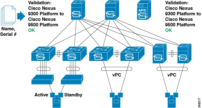
A clustered
logically centralized but physically distributed
APIC
provides policy, bootstrap, and image management for the entire fabric.
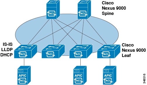
The
APIC
startup topology auto discovery, automated configuration, and infrastructure
addressing uses these industry-standard protocols: Intermediate
System-to-Intermediate System (IS-IS), Link Layer Discovery Protocol (LLDP),
and Dynamic Host Configuration Protocol (DHCP).
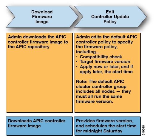
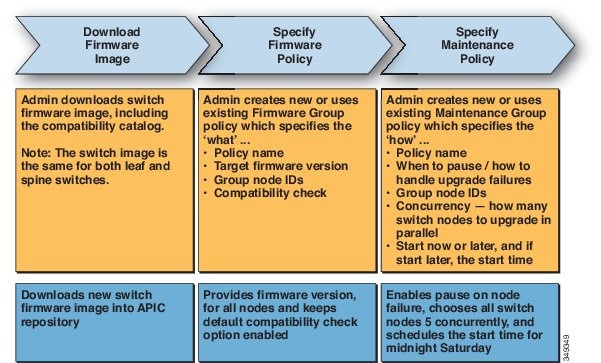
The
APIC
provides a simple and automated policy-based provisioning and upgrade process,
and automated image management.
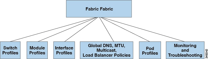
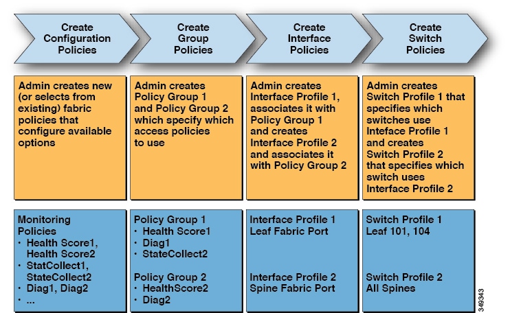
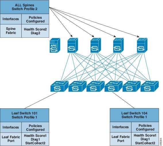
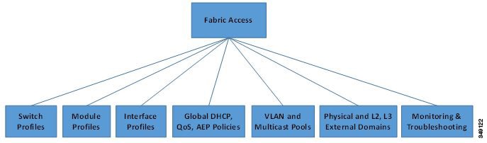
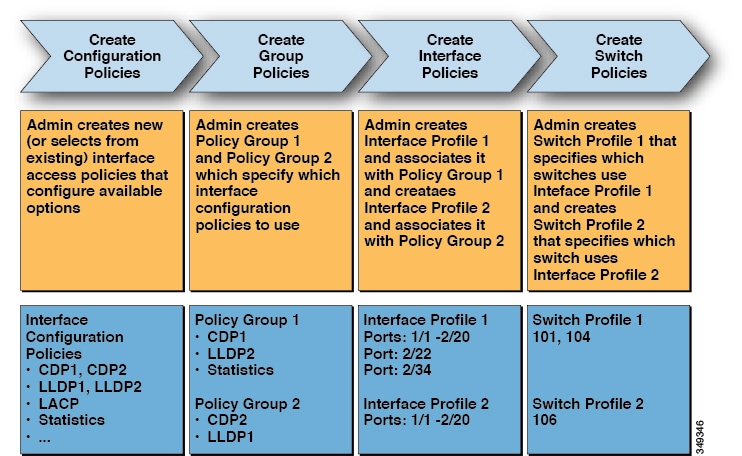
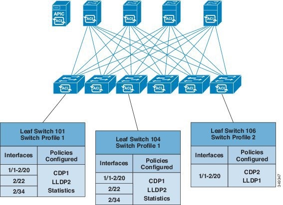
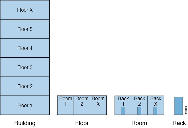
APIC
provides scalable configuration management. Because ACI data centers can be
very large, configuring switches or interfaces individually does not scale
well, even using scripts.
APIC
pod, controller, switch, module and interface selectors (all, range, specific
instances) enable symmetric configurations across the fabric. To apply a
symmetric configuration, an administrator defines switch profiles that
associate interface configurations in a single policy group. The configuration
is then rapidly deployed to all interfaces in that profile without the need to
configure them individually.
Startup Discovery
and Configuration
The clustered
APIC
controller provides DHCP, bootstrap configuration, and image management to the
fabric for automated startup and upgrades. The following figure shows startup
discovery.
Figure 1. Startup
Discovery Configuration
The Cisco Nexus ACI
fabric software is bundled as an ISO image, which can be installed on the Cisco
APIC
server through the KVM interface on the Cisco Integrated Management Controller
(CIMC). The Cisco Nexus ACI Software ISO contains the Cisco
APIC
image, the firmware image for the leaf node, the firmware image for the spine
node, default fabric infrastructure policies, and the protocols required for
operation.
The ACI fabric
bootstrap sequence begins when the fabric is booted with factory-installed
images on all the switches. The Cisco Nexus 9000 Series switches that run the
ACI firmware and
APICs
use a reserved overlay for the boot process. This infrastructure space is
hard-coded on the switches. The
APIC
can connect to a leaf through the default overlay, or it can use a locally
significant identifier.
The ACI fabric uses an
infrastructure space, which is securely isolated in the fabric and is where all
the topology discovery, fabric management, and infrastructure addressing is
performed. ACI fabric management communication within the fabric takes place in
the infrastructure space through internal private IP addresses. This addressing
scheme allows the
APIC
to communicate with fabric nodes and other Cisco
APIC
controllers in the cluster. The APIC discovers the IP address and node
information of other Cisco
APIC
controllers in the cluster using the Link Layer Discovery Protocol (LLDP)-based
discovery process.
The following
describes the
APIC
cluster discovery process:
Each
APIC
in the Cisco ACI uses an internal private IP address to communicate with the
ACI nodes and other
APICs
in the cluster. The
APIC
discovers the IP address of other
APIC
controllers in the cluster through the LLDP-based discovery process.
APICs
maintain an appliance vector (AV), which provides a mapping from an
APIC
ID to an
APIC
IP address and a universally unique identifier (UUID) of the
APIC.
Initially, each
APIC
starts with an AV filled with its local IP address, and all other
APIC
slots are marked as unknown.
When a switch
reboots, the policy element (PE) on the leaf gets its AV from the
APIC.
The switch then advertises this AV to all of its neighbors and reports any
discrepancies between its local AV and neighbors' AVs to all the
APICs
in its local AV.
Using this process,
the
APIC
learns about the other
APIC
controllers in the ACI through switches. After validating these newly
discovered
APIC
controllers in the cluster, the
APIC
controllers update their local AV and program the switches with the new AV.
Switches then start advertising this new AV. This process continues until all
the switches have the identical AV and all
APIC
controllers know the IP address of all the other
APIC
controllers.
Note
Prior to initiating
a change to the cluster, always verify its health. When performing planned
changes to the cluster, all controllers in the cluster should be healthy. If
one or more of the
APIC
controllers in the cluster is not healthy, remedy that situation before
proceeding with making changes to the cluster. Also, assure that cluster
controllers added to the
APIC
are running the same version of firmware as the other controllers in the
APIC
cluster. See the
KB: Cisco ACI APIC Cluster
Management article for guidelines that must be followed to assure
that making changes the
APIC
cluster complete normally.
The ACI fabric is
brought up in a cascading manner, starting with the leaf nodes that are
directly attached to the
APIC.
LLDP and control-plane IS-IS convergence occurs in parallel to this boot
process. The ACI fabric uses LLDP- and DHCP-based fabric discovery to
automatically discover the fabric switch nodes, assign the infrastructure VXLAN
tunnel endpoint (VTEP) addresses, and install the firmware on the switches.
Prior to this automated process, a minimal bootstrap configuration must be
performed on the Cisco
APIC
controller. After the
APIC
controllers are connected and their IP addresses assigned, the
APIC
GUI can be accessed by entering the address of any
APIC
controller into a web browser. The
APIC
GUI runs HTML5 and eliminates the need for Java to be installed locally.
Fabric
Inventory
The policy model
contains a complete real-time inventory of the fabric, including all nodes and
interfaces. This inventory capability enables automation of provisioning,
troubleshooting, auditing, and monitoring.
For Cisco ACI fabric
switches, the fabric membership node inventory contains policies that identify
the node ID, serial number, and name. Third-party nodes are recorded as
unmanaged fabric nodes. Cisco ACI switches can be automatically discovered, or
their policy information can be imported. The policy model also maintains
fabric member node state information.
Node States
Condition
Unknown
No policy. All nodes require a policy; without a policy, a
member node state is unknown.
Discovering
A transient state showing that the node is being discovered and
waiting for host traffic.
Undiscovered
The node has policy but has never been brought up in the fabric.
Unsupported
The node is a Cisco switch but it is not supported. For example,
the firmware version is not compatible with ACI fabric.
Decommissioned
The node has a policy, was discovered, but a user disabled it.
The node can be reenabled.
Note
Specifying the wipe option when decommissioning a leaf switch
results in the
APIC
attempting to remove all the leaf switch configurations on both the leaf switch
and on the
APIC.
If the leaf switch is not reachable, only the
APIC
is cleaned. In this case, the user must manually wipe the leaf switch by
resetting it.
Inactive
The node is unreachable. It had been discovered but currently is
not accessible. For example, it may be powered off, or its cables may be
disconnected.
Active
The node is an active member of the fabric.
Disabled interfaces
can be ones blacklisted by an administrator or ones taken down because the
APIC
detects anomalies. Examples of link state anomalies include the following:
A wiring mismatch,
such as a spine connected to a spine, a leaf connected to a leaf, a spine
connected to a leaf access port, a spine connected to a non-ACI node, or a leaf
fabric port connected to a non-ACI device.
A fabric name
mismatch. The fabric name is stored in each ACI node. If a node is moved to
another fabric without resetting it to a back to factory default state, it will
retain the fabric name.
A UUID mismatch
causes the
APIC
to disable the node.
Note
If an
administrator uses the
APIC
to disable all the leaf nodes on a spine, a spine reboot is required to recover
access to the spine.
Provisioning
The
APIC
provisioning method automatically brings up the ACI fabric with the appropriate
connections. The following figure shows fabric provisioning.
Figure 2. Fabric
Provisioning
After Link Layer
Discovery Protocol (LLDP) discovery learns all neighboring connections
dynamically, these connections are validated against a loose specification rule
such as "LEAF can connect to only SPINE-L1-*" or "SPINE-L1-* can connect to
SPINE-L2-* or LEAF." If a rule mismatch occurs, a fault occurs and the
connection is blocked because a leaf is not allowed to be connected to another
leaf, or a spine connected to a spine. In addition, an alarm is created to
indicate that the connection needs attention. The Cisco ACI fabric
administrator can import the names and serial numbers of all the fabric nodes
from a text file into the
APIC
or allow the fabric to discover the serial numbers automatically and then
assign names to the nodes using the
APIC
GUI, command-line interface (CLI), or API. The
APIC
is discoverable via SNMP. It has the following asysobjectId:
ciscoACIController OBJECT IDENTIFIER ::= { ciscoProducts 2238 }
Multi-Tier Architecture
3-tier Core-Aggregation-Access architectures are common in data center network topologies. As of the Cisco APIC Release 4.1(1), you can create a multi-tier ACI fabric topology that corresponds to the Core-Aggregation-Access architecture,
thus mitigating the need to upgrade costly components such as rack space or cabling. The addition of a tier-2 leaf layer makes
this topology possible. The tier-2 leaf layer supports connectivity to hosts or servers on the downlink ports and connectivity
to the leaf layer (aggregation) on the uplink ports.
In the multi-tier topology, the leaf switches initially have uplink connectivity to the spine switches and downlink connectivity
to the tier-2 leaf switches. To make the entire topology an ACI fabric, all ports on the leaf switches connecting to tier-2
leaf fabric ports must be configured as fabric ports (if not already using the default fabric ports). After APIC discovers
the tier-2 leaf switch, you can change the downlink port on the tier-2 leaf to a fabric port and connect to an uplink port
on the middle layer leaf.
The following figure shows an example of a multi-tier fabric topology.
Figure 3. Multi-Tier Fabric Topology Example
While the topology in the above image shows the Cisco APIC and L3Out/EPG connected to the leaf aggregation layer, the tier-2 leaf access layer also supports connectivity to APICs and
L3Out/EPGs.
APIC Cluster Management
Cluster Management
Guidelines
The APIC cluster is comprised of multiple APIC controllers that provide operators a unified real time monitoring, diagnostic,
and configuration management capability for the ACI fabric. To assure optimal system performance, follow the guidelines below
for making changes to the APIC cluster.
Note
Prior to initiating a change to the cluster, always verify its health. When performing planned changes to the cluster, all
controllers in the cluster should be healthy. If one or more of the APIC controllers' health status in the cluster is not
"fully fit", remedy that situation before proceeding. Also, assure that cluster controllers added to the APIC are running
the same version of firmware as the other controllers in the APIC cluster.
Follow these general
guidelines when managing clusters:
Cisco recommends that you have at least 3 active APICs in a cluster, along with additional standby APICs. A cluster size of
3, 5, or 7 APICs is recommended. A cluster size of 4 or 6 APICs is not recommended.
Disregard cluster information from APICs that are not currently in the cluster; they do not provide accurate cluster information.
Cluster slots contain an APIC ChassisID. Once you configure a slot, it remains unavailable until you decommission the APIC with the assigned ChassisID.
If an APIC firmware upgrade is in progress, wait for it to complete and the cluster to be fully fit before proceeding with
any other changes to the cluster.
When moving an APIC, first ensure that you have a healthy cluster. After verifying the health of the APIC Cluster, choose
the APIC you intend to shut down. After the APIC has shutdown, move the APIC, re-connect it, and then turn it back on. From
the GUI, verify that the all controllers in the cluster return to a fully fit state.
Note
Only move one APIC at a time.
When an APIC cluster is split into two or more groups, the ID of a node is changed and the changes are not synchronized across
all APICs. This can cause inconsistency in the node IDs between APICs and also the affected leaf nodes may not appear in the
inventory in the APIC GUI. When you split an APIC cluster, decommission the affected leaf nodes from APIC and register them
again, so that the inconsistency in the node IDs is resolved and the health status of the APICs in a cluster are in a fully
fit state.
Before configuring the APIC cluster, ensure that all the APICs are running the same firmware version. Initial clustering of
APICs running differing versions is an unsupported operation and may cause problems within the cluster.
This section contains the following topics:
About Cold Standby for a Cisco APIC Cluster
The Cold Standby functionality for a Cisco Application Policy Infrastructure Controller (APIC) cluster enables you to operate the Cisco APICs in a cluster in an Active/Standby mode. In a Cisco APIC cluster, the designated active Cisco APICs share the load and the designated standby Cisco APICs can act as a replacement for any of the Cisco APICs in the active cluster.
As an admin user, you can set up the Cold Standby functionality when the Cisco APIC is launched for the first time. We recommend that you have at least three active Cisco APICs in a cluster, and one or more standby Cisco APICs. As an admin user, you can initiate the switch over to replace an active Cisco APIC with a standby Cisco APIC.
Important Notes
The standby Cisco APICs are automatically updated with firmware updates to keep the backup Cisco APIC at same firmware version as the active cluster.
During an upgrade process, after all the active Cisco APICs are upgraded, the standby Cisco APICs are also upgraded automatically.
Temporary IDs are assigned to the standby Cisco APICs. After a standby Cisco APIC is switched over to an active Cisco APIC, a new ID is assigned.
The admin login is not enabled on the standby Cisco APICs. To troubleshoot a Cold StandbyCisco APIC, you must log in to the standby using SSH as rescue-user.
During the switch over, the replaced active Cisco APIC is powered down to prevent connectivity to the replaced Cisco APIC.
Switch over fails under the following conditions:
If there is no connectivity to the standby Cisco APIC.
If the firmware version of the standby Cisco APIC is not the same as that of the active cluster.
After switching over a standby Cisco APIC to be active, if it was the only standby, you must configure a new standby.
The following limitations are observed for retaining out of band address for the standby Cisco APIC after a fail over:
The standby (new active) Cisco APIC may not retain its out of band address if more than 1 active Cisco APICs are down or unavailable.
The standby (new active) Cisco APIC may not retain its out of band address if it is in a different subnet than the active Cisco APIC. This limitation is only applicable for Cisco APIC release 2.x.
The standby (new active) Cisco APIC may not retain its IPv6 out of band address. This limitation is not applicable starting from Cisco APIC release 3.1x.
The standby (new active) Cisco APIC may not retain its out of band address if you have configured a non-static OOB management IP address policy for the replacement
(old active) Cisco APIC.
The standby (new active) Cisco APIC may not retain its out of band address if it is not in a pod that has an active Cisco APIC.
Note
If you want to retain the standby Cisco APIC's out of band address despite the limitations, you must manually change the OOB policy for the replaced Cisco APIC after the replace operation had completed successfully.
There must be three active Cisco APICs to add a standby Cisco APIC.
The standby Cisco APIC does not participate in policy configuration or management.
No information is replicated to the standby Cisco APICs, not even the administrator credentials.
Maintenance Mode
Following are terms that are helpful to understand when using maintenance mode:
Graceful Insertion and Removal (GIR): The operation used to isolate a switch from user traffic.
Maintenance mode: Used to isolate a switch from user traffic for debugging purposes. You can put a switch in maintenance mode by enabling the Maintenance (GIR) field in the Fabric Membership page in the APIC GUI, located at Fabric > Inventory > Fabric Membership (right-click on a switch and choose Maintenance (GIR)).
If you put a switch in maintenance mode, that switch is not considered as a part of the operational ACI fabric infra and it will not accept regular APIC communications.
Therefore, performing a firmware upgrade for a switch in this state is not supported, since it may fail or may get stuck in
an incomplete status indefinitely if you attempt to perform a firmware upgrade on it while it is in this state.
The maintenance mode allows you to isolate a switch from the network with minimum service disruption. In the maintenance mode
you can perform real-time debugging without affecting traffic.
You can use maintenance mode to gracefully remove a switch and isolate it from the network in order to perform debugging operations.
The switch is removed from the regular forwarding path with minimal traffic disruption.
In graceful removal, all external protocols are gracefully brought down except the fabric
protocol (IS-IS) and the switch is isolated from the network. During maintenance mode,
the maximum metric is advertised in IS-IS within the Cisco Application Centric
Infrastructure (Cisco ACI) fabric and therefore the leaf switch in maintenance mode does not attract traffic
from the spine switches. In addition, all front-panel interfaces on the switch are
shutdown except for the fabric interfaces. To return the switch to its fully operational
(normal) mode after the debugging operations, you must recommission the switch. This
operation will trigger a stateless reload of the switch.
In graceful insertion, the switch is automatically decommissioned, rebooted, and
recommissioned. When recommissioning is completed, all external protocols are restored
and maximum metric in IS-IS is reset after 10 minutes.
Intermediate System-to-Intermediate System (IS-IS)
Open Shortest Path First (OSPF)
Link Aggregation Control Protocol (LACP)
Protocol Independent Multicast (PIM) is not supported.
Important Notes
If a border leaf switch has a static route and is placed in maintenance mode, the route from the border leaf switch might
not be removed from the routing table of switches in the ACI fabric, which causes routing issues.
To work around this issue, either:
Configure the same static route with the same administrative distance on the other border leaf switch, or
Use IP SLA or BFD for track reachability to the next hop of the static route
Upgrading or downgrading a switch in maintenance mode is not supported.
While the switch is in maintenance mode, the Ethernet port module stops propagating the interface related notifications. As
a result, if the remote switch is rebooted or the fabric link is flapped during this time, the fabric link will not come up
afterward unless the switch is manually rebooted (using the acidiag touch clean command), decommissioned, and recommissioned.
While the switch is in maintenance mode, CLI 'show' commands on the switch
show the front panel ports as being in the up state and the BGP protocol as
up and running. The interfaces are actually shut and all other adjacencies
for BGP are brought down, but the displayed active states allow for
debugging.
For multi-pod, IS-IS metric for redistributed routes should be set to less than 63. To set the IS-IS metric for redistributed routes, choose Fabric > Fabric Policies > Pod Policies > IS-IS Policy.
Existing GIR supports all Layer 3 traffic diversion. With LACP, all the Layer 2 traffic is also diverted to the redundant
node. Once a node goes into maintenance mode, LACP running on the node immediately informs neighbors that it can no longer
be aggregated as part of port-channel. All traffic is then diverted to the vPC peer node.
Stretched ACI Fabric
Design Overview
Stretched ACI fabric
is a partially meshed design that connects ACI leaf and spine switches
distributed in multiple locations. Typically, an ACI fabric implementation is a
single site where the full mesh design connects each leaf switch to each spine
switch in the fabric, which yields the best throughput and convergence. In
multi-site scenarios, full mesh connectivity may be not possible or may be too
costly. Multiple sites, buildings, or rooms can span distances that are not
serviceable by enough fiber connections or are too costly to connect each leaf
switch to each spine switch across the sites.
The following figure
illustrates a stretched fabric topology.
Figure 4. ACI Stretched
Fabric Topology
The stretched fabric is a single ACI fabric. The sites are one administration domain and one
availability zone. Administrators are able to manage the sites as one entity;
configuration changes made on any APIC controller node are applied to devices across the sites. The stretched ACI fabric
preserves live VM migration capability across the sites. The ACI stretched fabric design
has been validated, and is hence supported, on up to three interconnected sites.
An ACI stretched fabric
essentially represents a "stretched pod" extended across different locations. A more
solid, resilient (and hence recommended) way to deploy an ACI fabric in a distributed
fashion across different locations is offered since ACI release 2.0(1) with the ACI
Multi-Pod architecture. For more information, refer to the following white paper:
The
KB Stretched ACI Fabric Design
Overview technical note provides design guidelines regarding traffic
flow,
APIC
cluster redundancy and operational considerations for implementing an ACI
fabric stretched across multiple sites.
Fabric Policies
Overview
Fabric policies
govern the operation of internal fabric interfaces and enable the configuration
of various functions, protocols, and interfaces that connect spine and leaf
switches. Administrators who have fabric administrator privileges can create
new fabric policies according to their requirements. The
APIC
enables administrators to select the pods, switches, and interfaces to which
they will apply fabric policies. The following figure provides an overview of
the fabric policy model.
Figure 5. Fabric Polices
Overview
Fabric policies are
grouped into the following categories:
Switch profiles
specify which switches to configure and the switch configuration policy.
Module profiles
specify which spine switch modules to configure and the spine switch
configuration policy.
Interface
profiles specify which fabric interfaces to configure and the interface
configuration policy.
Global policies
specify DNS, fabric MTU default, multicast tree, and load balancer
configurations to be used throughout the fabric.
Pod profiles
specify date and time, SNMP, council of oracle protocol (COOP), IS-IS and Border
Gateway Protocol (BGP) route reflector policies.
Monitoring and
troubleshooting policies specify what to monitor, thresholds, how to handle
faults and logs, and how to perform diagnostics.
Fabric Policy
Configuration
Fabric policies
configure interfaces that connect spine and leaf switches. Fabric policies can
enable features such as monitoring (statistics collection and statistics
export), troubleshooting (on-demand diagnostics and SPAN), IS-IS, council of oracle protocol (COOP), SNMP, Border Gateway
Protocol (BGP) route reflectors, DNS,
or Network Time Protocol (NTP).
To apply a
configuration across the fabric, an administrator associates a defined group of
policies to interfaces on switches in a single step. In this way, large numbers
of interfaces across the fabric can be configured at once; configuring one port
at a time is not scalable. The following figure shows how the process works for
configuring the ACI fabric.
Figure 6. Fabric Policy
Configuration Process
The following figure
shows the result of applying Switch Profile 1 and Switch Profile 2 to the ACI
fabric.
Figure 7. Application of
a Fabric Switch Policy
This combination of
infrastructure and scope enables administrators to manage fabric configuration
in a scalable fashion. These configurations can be implemented using the REST
API, the CLI, or the GUI. The Quick Start Fabric Interface Configuration wizard
in the GUI automatically creates the necessary underlying objects to implement
such policies.
Access Policies
Overview
Access policies configure external-facing interfaces that connect to devices such as virtual machine controllers and hypervisors,
hosts, network attached storage, routers, or Fabric Extender (FEX) interfaces. Access policies enable the configuration of
port channels and virtual port channels, protocols such as Link Layer Discovery Protocol (LLDP), Cisco Discovery Protocol
(CDP), or Link Aggregation Control Protocol (LACP), and features such as statistics gathering, monitoring, and diagnostics.
The following figure provides an overview of the access policy model.
Figure 8. Access Policy Model Overview
Access policies are
grouped into the following categories:
Switch profiles
specify which switches to configure and the switch configuration policy.
Module profiles
specify which leaf switch access cards and access modules to configure and the
leaf switch configuration policy.
Interface
profiles specify which access interfaces to configure and the interface
configuration policy.
Global policies
enable the configuration of DHCP, QoS, and attachable access entity (AEP)
profile functions that can be used throughout the fabric. AEP profiles provide
a template to deploy hypervisor policies on a large set of leaf ports and
associate a Virtual Machine Management (VMM) domain and the physical network
infrastructure. They are also required for Layer 2 and Layer 3 external network
connectivity.
Pools specify
VLAN, VXLAN, and multicast address pools. A pool is a shared resource that can
be consumed by multiple domains such as VMM and Layer 4 to Layer 7 services. A
pool represents a range of traffic encapsulation ide.jpgiers (for example, VLAN
IDs, VNIDs, and multicast addresses).
Physical and
external domains policies include the following:
External
bridged domain Layer 2 domain profiles contain the port and VLAN specifications
that a bridged Layer 2 network connected to the fabric uses.
External
routed domain Layer 3 domain profiles contain the port and VLAN specifications
that a routed Layer 3 network connected to the fabric uses.
Physical
domain policies contain physical infrastructure specifications, such as ports
and VLAN, used by a tenant or endpoint group.
Monitoring and
troubleshooting policies specify what to monitor, thresholds, how to handle
faults and logs, and how to perform diagnostics.
Access Policy
Configuration
Access policies configure external-facing interfaces that do not connect to a spine switch. External-facing interfaces connect
to external devices such as virtual machine controllers and hypervisors, hosts, routers, or Fabric Extenders (FEXs). Access
policies enable an administrator to configure port channels and virtual port channels, protocols such as LLDP, CDP, or LACP,
and features such as monitoring or diagnostics.
Sample XML policies for switch interfaces, port channels, virtual port channels, and change interface speeds are provided
in Cisco APIC Rest API Configuration Guide.
Note
While tenant network policies are configured separately from fabric access policies, tenant policies are not activated unless
the underlying access policies they depend on are in place.
To apply a
configuration across a potentially large number of switches, an administrator
defines switch profiles that associate interface configurations in a single
policy group. In this way, large numbers of interfaces across the fabric can be
configured at once. Switch profiles can contain symmetric configurations for
multiple switches or unique special purpose configurations. The following
figure shows the process for configuring access to the ACI fabric.
Figure 9. Access Policy
Configuration Process
The following figure
shows the result of applying Switch Profile 1 and Switch Profile 2 to the ACI
fabric.
Figure 10. Applying an
Access Switch Policy
This combination of
infrastructure and scope enables administrators to manage fabric configuration
in a scalable fashion. These configurations can be implemented using the REST
API, the CLI, or the GUI. The Quick Start Interface, PC, VPC Configuration
wizard in the GUI automatically creates the necessary underlying objects to
implement such policies.
Port Channel and
Virtual Port Channel Access
Access policies enable an administrator to configure port channels and virtual port channels. Sample XML policies for switch
interfaces, port channels, virtual port channels, and change interface speeds are provided in Cisco APIC Rest API Configuration Guide.
FEX Virtual Port Channels
The ACI fabric supports Cisco Fabric Extender (FEX) server-side virtual port channels (vPC), also known as an FEX straight-through
vPC.
Note
When creating a vPC domain between two leaf switches, both switches must be in the same switch generation, one of the following:
Generation 1 - Cisco Nexus N9K switches without “EX” or "FX" on the end of the switch name; for example, N9K-9312TX
Generation 2 – Cisco Nexus N9K switches with “EX” or "FX" on the end of the switch model name; for example, N9K-93108TC-EX
Switches such as these two are not compatible vPC peers. Instead, use switches of the same generation.
Figure 11. Supported FEX vPC Topologies
Supported FEX vPC port channel topologies include the following:
Both VTEP and
non-VTEP hypervisors behind a FEX.
Virtual switches (such as AVS or VDS) connected to two FEXs that are connected to the ACI fabric (vPCs directly connected
on physical FEX ports is not supported - a vPC is supported only on port channels).
Note
When using GARP as the protocol to n.jpgy of IP to MAC binding changes to different interfaces on the same FEX you must set
the bridge domain mode to ARP Flooding and enable EP Move Detection Mode: GARP-based Detection, on the L3 Configuration page of the bridge domain wizard. This workaround is only required with Generation 1 switches. With Generation 2 switches
or later, this is not an issue.
Fibre Channel and FCoE
For Fibre Channel and FCoE configuration information, see the Cisco APIC Layer 2 Networking Configuration Guide.
Supporting Fibre
Channel over Ethernet Traffic on the ACI Fabric
Cisco ACI enables you to configure and manage support for Fibre Channel over Ethernet (FCoE) traffic on the ACI fabric.
FCoE is a protocol that encapsulates Fibre Channel (FC) packets within Ethernet packets, thus enabling storage traffic to
move seamlessly between a Fibre Channel SAN and an Ethernet network.
A typical implementation of FCoE protocol support on the ACI fabric enables hosts located on the Ethernet-based ACI fabric
to communicate with SAN storage devices located on an FC network. The hosts are connecting through virtual F ports deployed
on an ACI leaf switch. The SAN storage devices and FC network are connected through a Fibre Channel Forwarding (FCF) bridge
to the ACI fabric through a virtual NP port, deployed on the same ACI leaf switch as is the virtual F port. Virtual NP ports
and virtual F ports are also referred to generically as virtual Fibre Channel (vFC) ports.
Note
In the FCoE topology, the role of the ACI leaf switch is to provide a path for FCoE traffic between the locally connected
SAN hosts and a locally connected FCF device. The leaf switch does not perform local switching between SAN hosts, and the
FCoE traffic is not forwarded to a spine switch.
Topology Supporting FCoE Traffic Through ACI
The topology of a typical configuration supporting FCoE traffic over the ACI fabric consists of the following components:
Figure 12. ACI Topology Supporting FCoE Traffic
One or more ACI leaf switches configured through FC SAN policies to function as an NPV backbone.
Selected interfaces on the NPV-configured leaf switches configured to function as virtual F ports, which accommodate FCoE
traffic to and from hosts running SAN management or SAN-consuming applications.
Selected interfaces on the NPV-configured leaf switches configured to function as virtual NP ports, which accommodate FCoE
traffic to and from a Fibre Channel Forwarding (FCF) bridge.
The FCF bridge receives FC traffic from fibre channel links typically connecting SAN storage devices and encapsulates the
FC packets into FCoE frames for transmission over the ACI fabric to the SAN management or SAN Data-consuming hosts. It receives
FCoE traffic and repackages it back to FC for transmission over the fibre channel network.
Note
In the above ACI topology, FCoE traffic support requires direct connections between the hosts and virtual F ports and direct
connections between the FCF device and the virtual NP port.
APIC servers enable an operator to configure and monitor the FCoE traffic through the APIC GUI, the APIC NX-OS style CLI,
or through application calls to the APIC REST API.
Topology
Supporting FCoE Initialization
In order for FCoE traffic flow to take place as described, you must also set up separate VLAN connectivity over which SAN
Hosts broadcast FCoE Initialization protocol (FIP) packets to discover the interfaces enabled as F ports.
vFC
Interface Configuration Rules
Whether you set up the vFC network and EPG deployment through the APIC GUI, NX-OS style CLI, or the REST API, the following
general rules apply across platforms:
F port mode
is the default mode for vFC ports. NP port mode must be specifically configured
in the Interface policies.
The load
balancing default mode is for leaf-switch or interface level vFC configuration
is src-dst-ox-id.
One VSAN
assignment per bridge domain is supported.
The
allocation mode for VSAN pools and VLAN pools must always be static.
vFC ports require association with a VSAN domain (also called Fibre Channel domain) that contains VSANs mapped to VLANs.
Fibre Channel Connectivity Overview
A switch is in NPV mode after enabling NPV. NPV mode applies to an entire switch. All end devices connected to a switch that
are in NPV mode must log in as an N port to use this feature (loop-attached devices are not supported). All links from the
edge switches (in NPV mode) to the NPV core switches are established as NP ports (not E ports), which are used for typical
inter-switch links.
FC NPV Benefits
FC NPV provides the following:
Increased number of hosts that connect to the fabric without adding domain IDs in the fabric
Connection of FC and FCoE hosts and targets to SAN fabrics using FC interfaces
Automatic traffic mapping
Static traffic mapping
Disruptive automatic load balancing
FC NPV Mode
Feature-set fcoe-npv in ACI will be enabled automatically by default when first FCoE/FC configuration is pushed.
FC Topology
The topology of a typical configuration supporting FC traffic over the ACI fabric consists of the following components:
A Leaf can be connected to a FC switch by using FCoE NP port or native FC NP port.
An ACI Leaf can be directly connected with a server/Storage using FCoE links.
FC/FCoE traffic is not sent to fabric/spine. A Leaf switch does not do local switching for FCoE traffic. The switching is
done by a core switch which is connected with a leaf switch via FC/FCoE NPV link.
Multiple FDISC followed by Flogi is supported with FCoE host and FC/FCoE NP links.
802.1Q Tunnels
About ACI 802.1Q Tunnels
Figure 13. ACI 802.1Q Tunnels
With Cisco ACI and Cisco APIC Release 2.2(1x) and higher, you can configure 802.1Q tunnels on edge (tunnel) ports to enable point-to-multi-point tunneling
of Ethernet frames in the fabric, with Quality of Service (QoS) priority settings. A Dot1q Tunnel transports untagged, 802.1Q tagged, and 802.1ad double-tagged frames as-is across the fabric. Each tunnel carries the traffic
from a single customer and is associated with a single bridge domain. ACI front panel ports can be part of a Dot1q Tunnel. Layer 2 switching is done based on Destination MAC (DMAC) and regular MAC learning is done in the tunnel. Edge-port Dot1q Tunnels are supported on second-generation (and later) Cisco Nexus 9000 series switches with "EX" on the end of the switch model
name.
With Cisco ACI and Cisco APIC Release 2.3(x) and higher, you can also configure multiple 802.1Q tunnels on the same
core port to carry double-tagged traffic from multiple customers, each distinguished
with an access encapsulation configured for each 802.1Q tunnel. You can also disable MAC
Address Learning on 802.1Q tunnels. Both edge ports and core ports can belong to an
802.1Q tunnel with access encapsulation and disabled MAC Address Learning. Both edge
ports and core ports in Dot1q Tunnels are supported on
third-generation Cisco Nexus 9000 series switches with "FX" and "FX2" on the end of the
switch model name.
Terms used in this document may be different in the Cisco Nexus 9000 Series documents.
Table 1. 802.1Q Tunnel Terminology
ACI Documents
Cisco Nexus 9000 Series Documents
Edge Port
Tunnel Port
Core Port
Trunk Port
The following guidelines and restrictions apply:
Layer 2 tunneling of VTP, CDP, LACP, LLDP, and STP protocols is supported with the following restrictions:
Link Aggregation Control Protocol (LACP) tunneling functions as expected only with point-to-point tunnels using individual
leaf interfaces. It is not supported on port-channels (PCs) or virtual port-channels (vPCs).
CDP and LLDP tunneling with PCs or vPCs is not deterministic; it depends on the link it chooses as the traffic destination.
To use VTP for Layer 2 protocol tunneling, CDP must be enabled on the tunnel.
STP is not supported in an 802.1Q tunnel bridge domain when Layer 2 protocol tunneling is enabled and the bridge domain is
deployed on Dot1q Tunnel core ports.
ACI leaf switches react to STP TCN packets by flushing the end points in the tunnel bridge domain and flooding them in the
bridge domain.
CDP and LLDP tunneling with more than two interfaces flood packets on all interfaces.
With Cisco APIC Release 2.3(x) or higher, the destination MAC address of Layer 2 protocol packets tunneled from edge to core
ports is rewritten as 01-00-0c-cd-cd-d0 and the destination MAC address of Layer 2 protocol packets tunneled from core to
edge ports is rewritten with the standard default MAC address for the protocol.
If a PC or vPC is the only interface in a Dot1q Tunnel and it is deleted and reconfigured, remove the association of the PC/VPC to the Dot1q Tunnel and reconfigure it.
For 802.1Q tunnels deployed on switches that have EX in the product ID, Ethertype combinations of 0x8100+0x8100, 0x8100+0x88a8,
0x88a8+0x8100, and 0x88a8+0x88a8 for the first two VLAN tags are not supported.
If the tunnels are deployed on a combination of EX and FX or later switches, then this restriction still applies.
If the tunnels are deployed only on switches that have FX or later in the product ID, then this restriction does not apply.
For core ports, the Ethertypes for double-tagged frames must be 0x8100 followed by 0x8100.
You can include multiple edge ports and core ports (even across leaf switches) in a Dot1q Tunnel.
An edge port may only be part of one tunnel, but a core port can belong to multiple Dot1q tunnels.
With Cisco APIC Release 2.3(x) and higher, regular EPGs can be deployed on core ports that are used in 802.1Q tunnels.
L3Outs are not supported on interfaces enabled for Dot1q Tunnels.
FEX interfaces are not supported as members of a Dot1q Tunnel.
Interfaces configured as breakout ports do not support 802.1Q tunnels.
Interface-level statistics are supported for interfaces in Dot1q Tunnels, but statistics at the tunnel level are not supported.
Dynamic Breakout Ports
Configuration of Dynamic Breakout Ports
Breakout cables are suitable for very short links and offer a cost effective way to connect within racks and across adjacent
racks.
Breakout enables a 40 Gigabit (Gb) port to be split into four independent and logical 10Gb ports or a 100Gb port to be split
into four independent and logical 25Gb ports.
Before you configure breakout ports, connect a 40Gb port to four 10Gb ports or a 100Gb port to four 25Gb ports with one of
the following cables:
Cisco QSFP-4SFP10G
Cisco QSFP-4SFP25G
The 40Gb to 10Gb dynamic breakout feature is supported on the access facing ports of the following switches:
N9K-C9332PQ
N9K-C93180LC-EX
N9K-C9336C-FX
The 100Gb to 25Gb breakout feature is supported on the access facing ports of the following switches:
N9K-C93180LC-EX
N9K-C9336C-FX2
N9K-C93180YC-FX in the 3.2 and later releases
Observe the following guidelines and restrictions:
In general, breakout ports and port profiles (ports changed from uplink to downlink) are not supported on the same port.
However, from Cisco Application Policy Infrastructure Controller (APIC) release 3.2, dynamic breakouts (both 100Gb and 40Gb) are supported on profiled QSFP ports on the N9K-C93180YC-FX switch.
Fast Link Failover policies are not supported on the same port with the dynamic breakout feature.
Breakout ports cannot be used for Cisco APIC connectivity.
Breakout subports can be used in the same way other port types in the policy model are used.
When a port is enabled for dynamic breakout, other policies (expect monitoring policies) on the parent port are no longer
valid.
When a port is enabled for dynamic breakout, other EPG deployments on the parent port are no longer valid.
A breakout sub-port can not be further broken out using a breakout policy group.
If the LACP transmit rate on port channels that have breakout sub-ports need to be changed, then all the port channels that
include breakout sub-ports need to use the same LACP transmit rate configuration. You can configure an override policy to
set the transmit rate as follows:
Configure/change the default port channel member policy to include Fast Transmit Rate (Fabric > Access Policies > Policies > Interface > Port Channel Member).
Configure all the PC/vPC interface policy groups to include the above default port channel member policy under the override
policy groups (Fabric > Access Policies > Interfaces > Leaf Interfaces > Policy Groups > PC/vPC Interface).
Configuring Port Profiles
Prior to Cisco APIC, Release 3.1(1), conversion from uplink port to downlink port or downlink port to uplink port (in a port
profile) was not supported on Cisco ACI leaf switches. Starting with Cisco APIC Release 3.1(1), uplink and downlink conversion
is supported on Cisco Nexus 9000 series switches with names that end in EX or FX, and later (for example, N9K-C9348GC-FXP).
A FEX connected to converted downlinks is also supported.
This functionality is supported on the following Cisco switches:
N9K-C9348GC-FXP
N9K-C93180LC-EX and N9K-C93180YC-FX
N9K-C93108TC-EX and N9K-C93108TC-FX (only uplink to downlink conversion is supported)
N9K-C9336C-FX2 (only downlink to uplink conversion is supported)
Restrictions
Fast Link Failover policies and port profiles are not supported on the same port. If port profile is enabled, Fast Link Failover
cannot be enabled or vice versa.
The last 2 uplink ports of supported TOR switches cannot be converted to downlink ports (they are reserved for uplink connections.)
Up to Cisco APIC Release 3.2, port profiles and breakout ports are not supported on the same ports.
Guidelines
In converting uplinks to downlinks and downlinks to uplinks, consider the following guidelines.
Subject
Guideline
Decommissioning nodes with port profiles
If a decommissioned node has the Port Profile feature deployed on it, the port conversions are not removed even after decommissioning
the node. It is necessary to manually delete the configurations after decommission, for the ports to return to the default
state. To do this, log onto the switch, run the setup-clean-config.sh script, and wait for it to run. Then, enter the reload command.
FIPS
When you enable or disable Federal Information Processing Standards (FIPS) on a Cisco ACI fabric, you must reload each of
the switches in the fabric for the change to take effect. The configured scale profile setting is lost when you issue the
first reload after changing the FIPS configuration. The switch remains operational, but it uses the default scale profile.
This issue does not happen on subsequent reloads if the FIPS configuration has not changed.
FIPS is supported on Cisco NX-OS release 13.1(1) or later.
If you must downgrade the firmware from a release that supports FIPS to a release that does not support FIPS, you must first
disable FIPS on the Cisco ACI fabric and reload all the switches in the fabric for the FIPS configuration change.
Maximum uplink port limit
When the maximum uplink port limit is reached and ports 25 and 27 are converted from uplink to downlink and back to uplink
on Cisco 93180LC-EX switches:
On Cisco 93180LC-EX Switches, ports 25 and 27 are the native uplink ports. Using the port profile, if you convert port 25
and 27 to downlink ports, ports 29, 30, 31, and 32 are still available as four native uplink ports. Because of the threshold
on the number of ports (which is maximum of 12 ports) that can be converted, you can convert 8 more downlink ports to uplink
ports. For example, ports 1, 3, 5, 7, 9, 13, 15, 17 are converted to uplink ports and ports 29, 30, 31 and 32 are the 4 native
uplink ports (the maximum uplink port limit on Cisco 93180LC-EX switches).
When the switch is in this state and if the port profile configuration is deleted on ports 25 and 27, ports 25 and 27 are
converted back to uplink ports, but there are already 12 uplink ports on the switch (as mentioned earlier). To accommodate
ports 25 and 27 as uplink ports, 2 random ports from the port range 1, 3, 5, 7, 9, 13, 15, 17 are denied the uplink conversion
and this situation cannot be controlled by the user.
Therefore, it is mandatory to clear all the faults before reloading the leaf node to avoid any unexpected behavior regarding
the port type. It should be noted that if a node is reloaded without clearing the port profile faults, especially when there
is a fault related to limit-exceed, the port might not be in an expected operational state.
Breakout Limitations
Switch
Releases
Limitations
N9K-C9332PQ
Cisco APIC 2.2 (1n) and higher
40Gb dynamic breakouts into 4X10Gb ports are supported.
Ports 13 and 14 do not support breakouts.
Port profiles and breakouts are not supported on the same port.
N9K-C93180LC-EX
Cisco APIC 3.1(1i) and higher
40Gb and 100Gb dynamic breakouts are supported on ports 1 through 24 on odd numbered ports.
When the top ports (odd ports) are broken out, then the bottom ports (even ports) are error disabled.
Port profiles and breakouts are not supported on the same port.
N9K-C9336C-FX2
Cisco APIC 3.1(2m) and higher
40Gb and 100Gb dynamic breakouts are supported on ports 1 through 30.
Port profiles and breakouts are not supported on the same port.
Port Tracking Policy for Fabric Port Failure Detection
Fabric port failure detection can be enabled in the fabric access global port tracking policy. The port tracking policy monitors
the status of fabric ports between leaf switches and spine switches, and ports between tier-1 leaf switches and tier-2 leaf.
When an enabled port tracking policy is triggered, the leaf switches take down all access interfaces on the switch that have
EPGs deployed on them.
Note
Port tracking is located under Fabric > External Access Policies > Policies > Global > Port Tracking.
The port tracking policy specifies the number of fabric port connections that trigger the policy, and a delay timer for
bringing the leaf switch access ports back up after the number of specified fabric ports is exceeded.
The following example illustrates how a port tracking policy behaves:
The port tracking policy specifies that the threshold of active fabric port connections each leaf switch that triggers the
policy is 2.
The port tracking policy triggers when the number of active fabric port connections from the leaf switch to the spine switches
drops to 2.
Each leaf switch monitors its fabric port connections and triggers the port tracking policy according to the threshold specified
in the policy.
When the fabric port connections come back up, the leaf switch waits for the delay timer to expire before bringing its access
ports back up. This gives the fabric time to reconverge before allowing traffic to resume on leaf switch access ports. Large
fabrics may need the delay timer to be set for a longer time.
Note
Use caution when configuring this policy. If the port tracking setting for the number of active spine ports that triggers
port tracking is too high, all leaf switch access ports will be brought down.
Q-in-Q Encapsulation Mapping for EPGs
Using Cisco Application Policy Infrastructure Controller (APIC), you can map double-tagged VLAN traffic ingressing on a regular interface, PC, or vPC to an EPG. When this feature is enabled,
when double-tagged traffic enters the network for an EPG, both tags are processed individually in the fabric and restored
to double-tags when egressing the Cisco Application Centric
Infrastructure (ACI) switch. Ingressing single-tagged and untagged traffic is dropped.
The following guidelines and limitations apply:
This feature is only supported on Cisco Nexus 9300-FX platform switches.
Both the outer and inner tag must be of EtherType 0x8100.
MAC learning and routing are based on the EPG port, sclass, and VRF instance, not on the access encapsulations.
QoS priority settings are supported, derived from the outer tag on ingress, and rewritten to both tags on egress.
EPGs can simultaneously be associated with other interfaces on a leaf switch, that are configured for single-tagged VLANs.
Service graphs are supported for provider and consumer EPGs that are mapped to Q-in-Q encapsulated interfaces. You can insert
service graphs, as long as the ingress and egress traffic on the service nodes is in single-tagged encapsulated frames.
When vPC ports are enabled for Q-in-Q encapsulation mode, VLAN consistency checks are not performed.
The following features and options are not supported with this feature:
Per-port VLAN feature
FEX connections
Mixed mode
For example, an interface in Q-in-Q encapsulation mode can have a static path binding to an EPG with double-tagged encapsulation
only, not with regular VLAN encapsulation.
STP and the "Flood in Encapsulation" option
Untagged and 802.1p mode
Multi-pod and Multi-Site
Legacy bridge domain
L2Out and L3Out connections
VMM integration
Changing a port mode from routed to Q-in-Q encapsulation mode
Per-VLAN mis-cabling protocol on ports in Q-in-Q encapsulation mode
Layer 2 Multicast
About Cisco APIC
and IGMP Snooping
IGMP snooping is the
process of listening to Internet Group Management Protocol (IGMP) network
traffic. The feature allows a network switch to listen in on the IGMP
conversation between hosts and routers and filter multicasts links that do not
need them, thus controlling which ports receive specific multicast traffic.
Cisco APIC provides
support for the full IGMP snooping feature included on a traditional switch
such as the N9000 standalone.
Policy-based
IGMP snooping configuration per bridge domain
APIC enables you
to configure a policy in which you enable, disable, or customize the properties
of IGMP Snooping on a per bridge-domain basis. You can then apply that policy
to one or multiple bridge domains.
Static port
group implementation
IGMP static port
grouping enables you to pre-provision ports, already statically-assigned to an
application EPG, as the switch ports to receive and process IGMP multicast
traffic. This pre-provisioning prevents the join latency which normally occurs
when the IGMP snooping stack learns ports dynamically.
Static group
membership can be pre-provisioned only on static ports (also called, static-binding ports)
assigned to an application EPG.
Access group
configuration for application EPGs
An
“access-group” is used to control what streams can be joined behind a given
port.
An access-group
configuration can be applied on interfaces that are statically assigned to an
application EPG in order to ensure that the configuration can be applied on
ports that will actually belong to the that EPG.
To use vzAny, navigate to Tenants > tenant-name > Networking > VRFs > vrf-name > EPG Collection for VRF.
How IGMP Snooping
is Implemented in the ACI Fabric
Note
We recommend that you do not disable IGMP snooping on bridge domains. If you disable IGMP snooping, you may see reduced multicast
performance because of excessive false flooding within the bridge domain.
IGMP snooping software examines IP multicast traffic within a bridge domain to discover the ports where interested receivers
reside. Using the port information, IGMP snooping can reduce bandwidth consumption in a multi-access bridge domain environment
to avoid flooding the entire bridge domain. By default, IGMP snooping is enabled on the bridge domain.
This figure shows the IGMP routing functions and IGMP snooping functions both contained on an ACI leaf switch with connectivity
to a host. The IGMP snooping feature snoops the IGMP membership reports, and leaves messages and forwards them only when necessary
to the IGMP router function.
Figure 14. IGMP Snooping
function
IGMP snooping operates
upon IGMPv1, IGMPv2, and IGMPv3 control plane packets where Layer 3 control
plane packets are intercepted and influence the Layer 2 forwarding behavior.
IGMP snooping has the
following proprietary features:
Source filtering that
allows forwarding of multicast packets based on destination and source IP
addresses
Multicast forwarding based
on IP addresses rather than the MAC address
Multicast forwarding
alternately based on the MAC address
The ACI fabric supports IGMP snooping only in proxy-reporting mode, in accordance with the guidelines provided in Section
2.1.1, "IGMP Forwarding Rules," in RFC 4541:
IGMP networks may also include devices that implement "proxy-
reporting", in which reports received from downstream hosts are
summarized and used to build internal membership states. Such
proxy-reporting devices may use the all-zeros IP Source-Address
when forwarding any summarized reports upstream. For this reason,
IGMP membership reports received by the snooping switch must not
be rejected because the source IP address is set to 0.0.0.0.
As a result, the ACI fabric will send IGMP reports with the source IP address of 0.0.0.0.
Note
For more
information about IGMP snooping, see RFC 4541.
Virtualization
Support
You can define multiple
virtual routing and forwarding (VRF) instances for IGMP snooping.
On leaf switches, you can
use the
show commands with a VRF argument to provide a context
for the information displayed. The default VRF is used if no VRF argument is
supplied.
The APIC IGMP
Snooping Function, IGMPv1, IGMPv2, and the Fast Leave Feature
Both IGMPv1 and IGMPv2
support membership report suppression, which means that if two hosts on the
same subnet want to receive multicast data for the same group, the host that
receives a member report from the other host suppresses sending its report.
Membership report suppression occurs for hosts that share a port.
If no more than one host is
attached to each switch port, you can configure the fast leave feature in
IGMPv2. The fast leave feature does not send last member query messages to
hosts. As soon as APIC receives an IGMP leave message, the software stops
forwarding multicast data to that port.
IGMPv1 does not provide an
explicit IGMP leave message, so the APIC IGMP snooping function must rely on
the membership message timeout to indicate that no hosts remain that want to
receive multicast data for a particular group.
Note
The IGMP snooping function
ignores the configuration of the last member query interval when you enable the
fast leave feature because it does not check for remaining hosts.
The APIC IGMP
Snooping Function and IGMPv3
The IGMPv3 snooping
function in APIC supports full IGMPv3 snooping, which provides constrained
flooding based on the (S, G) information in the IGMPv3 reports. This
source-based filtering enables the device to constrain multicast traffic to a
set of ports based on the source that sends traffic to the multicast group.
By default, the IGMP
snooping function tracks hosts on each VLAN port in the bridge domain. The
explicit tracking feature provides a fast leave mechanism. Because every IGMPv3
host sends membership reports, report suppression limits the amount of traffic
that the device sends to other multicast-capable routers. When report
suppression is enabled, and no IGMPv1 or IGMPv2 hosts requested the same group,
the IGMP snooping function provides proxy reporting. The proxy feature builds
the group state from membership reports from the downstream hosts and generates
membership reports in response to queries from upstream queriers.
Even though the IGMPv3
membership reports provide a full accounting of group members in a bridge
domain, when the last host leaves, the software sends a membership query. You
can configure the parameter last member query interval. If no host responds
before the timeout, the IGMP snooping function removes the group state.
Cisco APIC and the
IGMP Snooping Querier Function
When PIM is not enabled on an interface because the multicast traffic does not need to be routed, you must configure an IGMP
snooping querier function to send membership queries. In APIC, within the IGMP Snoop policy, you define the querier in a bridge
domain that contains multicast sources and receivers but no other active querier.
Cisco ACI has by default, IGMP snooping and IGMP snooping querier enabled. Additionally, if the Bridge Domain subnet control
has “querier IP” selected, then the leaf switch behaves as a querier and starts sending query packets. Querier on the ACI
leaf switch must be enabled when the segments do not have an explicit multicast router (PIM is not enabled). On the Bridge
Domain where the querier is configured, the IP address used must be from the same subnet where the multicast hosts are configured.
A unique IP address must be configured so as to easily reference the querier function. You must use a unique IP address for
IGMP snooping querier configuration, so that it does not overlap with any host IP address or with the IP addresses of routers
that are on the same segment. The SVI IP address must not be used as the querier IP address or it will result in issues with
querier election. As an example, if the IP address used for IGMP snooping querier is also used for another router on the segment,
then there will be issues with the IGMP querier election protocol. The IP address used for querier functionality must also
not be used for other functions, such as HSRP or VRRP.
Note
The IP address for
the querier should not be a broadcast IP address, multicast IP address, or 0
(0.0.0.0).
When an IGMP snooping
querier is enabled, it sends out periodic IGMP queries that trigger IGMP report
messages from hosts that want to receive IP multicast traffic. IGMP snooping
listens to these IGMP reports to establish appropriate forwarding.
The IGMP snooping
querier performs querier election as described in RFC 2236. Querier election
occurs in the following configurations:
When there are
multiple switch queriers configured with the same subnet on the same VLAN on
different switches.
When the
configured switch querier is in the same subnet as with other Layer 3 SVI
queriers.
Fabric Secure Mode
Fabric secure mode prevents parties with physical access to the fabric equipment from adding a switch or APIC controller to
the fabric without manual authorization by an administrator. Starting with release 1.2(1x), the firmware checks that switches
and controllers in the fabric have valid serial numbers associated with a valid Cisco digitally signed certificate. This validation
is performed upon upgrade to this release or during an initial installation of the fabric. The default setting for this feature
is permissive mode; an existing fabric continues to run as it has after an upgrade to release 1.2(1) or later. An administrator
with fabric-wide access rights must enable strict mode. The following table summarizes the two modes of operation:
Permissive Mode (default)
Strict Mode
Allows an existing fabric to operate normally even though one or more switches have an invalid certificate.
Only switches with a valid Cisco serial number and SSL certificate are allowed.
Does not enforce serial number based authorization .
Enforces serial number authorization.
Allows auto-discovered controllers and switches to join the fabric without enforcing serial number authorization.
Requires an administrator to manually authorize controllers and switches to join the fabric.
Configuring Fast Link Failover Policy
Fast Link Failover policy is applicable to uplinks on Cisco N9K-C93180YC-EX and N9K-C93180YC-FX platforms only. It efficiently
load balances the traffic based on the uplink MAC status. With this functionality, the switch performs Layer 2 or Layer 3
lookup and it provides an output Layer 2 interface (uplinks) based on the packet hash algorithm by considering the uplink
status. This functionality reduces the data traffic convergence to less than 200 milliseconds.
See the following limitations on configuring Fast Link Failover:
Fast Link Failover and port profiles are not supported on the same interface. If port profile is enabled, Fast Link Failover
cannot be enabled or vice versa.
Configuring remote leaf does not work with Fast Link Failover. In this case, Fast Link Failover policies will not work and
no fault will be generated.
When Fast Link Failover policy is enabled, configuring SPAN on individual uplinks will not work. No fault will be generated
while attempting to enable SPAN on individual uplinks but Fast Link Failover policy can be enabled on all uplinks together
or it can be enabled on an individual downlink.
Note
Fast Link Failover is located under Fabric > Access Policies > Switch Policies > Policies > Fast Link Failover.
In Cisco APIC Release 3.2(1) and later releases, Fast Link Failover is located under Fabric > External Access Policies > Policies > Switch > Fast Link Failover.
About Port Security and ACI
The port security feature protects the ACI fabric from being flooded with unknown MAC addresses by limiting the number of
MAC addresses learned per port. The port security feature support is available for physical ports, port channels, and virtual
port channels.
Port Security and
Learning Behavior
For non-vPC ports or
port channels, whenever a learn event comes for a new endpoint, a verification
is made to see if a new learn is allowed. If the corresponding interface has a
port security policy not configured or disabled, the endpoint learning behavior
is unchanged with what is supported. If the policy is enabled and the limit is
reached, the current supported action is as follows:
Learn the
endpoint and install it in the hardware with a drop action.
Silently discard
the learn.
If the limit is not
reached, the endpoint is learned and a verification is made to see if the limit
is reached because of this new endpoint. If the limit is reached, and the learn
disable action is configured, learning will be disabled in the hardware on that
interface (on the physical interface or on a port channel or vPC). If the limit
is reached and the learn disable action is not configured, the endpoint will be
installed in hardware with a drop action. Such endpoints are aged normally like
any other endpoints.
When the limit is
reached for the first time, the operational state of the port security policy
object is updated to reflect it. A static rule is defined to raise a fault so
that the user is alerted. A syslog is also raised when the limit is reached.
In case of vPC,
when the MAC limit is reached, the peer leaf switch is also notified so
learning can be disabled on the peer. As the vPC peer can be rebooted any time
or vPC legs can become unoperational or restart, this state will be reconciled
with the peer so vPC peers do not go out of sync with this state. If they get
out of sync, there can be a situation where learning is enabled on one leg and
disabled on the other leg.
By default, once the limit is reached and learning is disabled, it will be automatically re-enabled after the default timeout
value of 60 seconds.
Protect
Mode
The protect mode prevents further port security violations from occurring. Once the MAC limit exceeds the maximum configured
value on a port, all traffic from excess MAC addresses will be dropped and further learning is disabled.
Port Security at
Port Level
In the APIC, the user can configure the port security on switch ports. Once the MAC limit has exceeded the maximum configured
value on a port, all traffic from the exceeded MAC addresses is forwarded. The following attributes are supported:
Port Security Timeout—The current supported range for the timeout value is from 60 to 3600 seconds.
Violation Action—The violation action is available in protect mode. In the protect mode, MAC learning is disabled and MAC addresses are not
added to the CAM table. Mac learning is re-enabled after the configured timeout value.
Maximum Endpoints—The current supported range for the maximum endpoints configured value is from 0 to 12000. If the maximum endpoints value
is 0, the port security policy is disabled on that port.
Port Security
Guidelines and Restrictions
The guidelines and
restrictions are as follows:
Port security is
available per port.
Port security is
supported for physical ports, port channels, and virtual port channels (vPCs).
Static and
dynamic MAC addresses are supported.
MAC address
moves are supported from secured to unsecured ports and from unsecured ports to
secured ports.
The MAC address
limit is enforced only on the MAC address and is not enforced on a MAC and IP
address.
Port security is
not supported with the Fabric Extender (FEX).
About First Hop Security
First-Hop Security (FHS) features enable a better IPv4 and IPv6 link security and management over the layer 2 links. In a
service provider environment, these features closely control address assignment and derived operations, such as Duplicate
Address Detection (DAD) and Address Resolution (AR).
The following supported FHS features secure the protocols and help build a secure endpoint database on the fabric leaf switches,
that are used to mitigate security threats such as MIM attacks and IP thefts:
ARP Inspection—allows a network administrator to intercept, log, and discard ARP packets with invalid MAC address to IP address
bindings.
ND Inspection—learns and secures bindings for stateless autoconfiguration addresses in Layer 2 neighbor tables.
DHCP Inspection—validates DHCP messages received from untrusted sources and filters out invalid messages.
RA Guard—allows the network administrator to block or reject unwanted or rogue router advertisement (RA) guard messages.
IPv4 and IPv6 Source Guard—blocks any data traffic from an unknown source.
Trust Control—a trusted source is a device that is under your administrative control. These devices include the switches,
routers, and servers in the Fabric. Any device beyond the firewall or outside the network is an untrusted source. Generally,
host ports are treated as untrusted sources.
FHS features provide the following security measures:
Role Enforcement—Prevents untrusted hosts from sending messages that are out the scope of their role.
Binding Enforcement—Prevents address theft.
DoS Attack Mitigations—Prevents malicious end-points to grow the end-point database to the point where the database could stop providing operation
services.
Proxy Services—Provides some proxy-services to increase the efficiency of address resolution.
FHS features are enabled on a per tenant bridge domain (BD) basis. As the bridge domain, may be deployed on a single or across
multiple leaf switches, the FHS threat control and mitigation mechanisms cater to a single switch and multiple switch scenarios.
About MACsec
MACsec is an IEEE 802.1AE standards based Layer 2 hop-by-hop encryption that provides data confidentiality and integrity for
media access independent protocols.
MACsec, provides MAC-layer encryption over wired networks by using out-of-band methods for encryption keying. The MACsec Key
Agreement (MKA) Protocol provides the required session keys and manages the required encryption keys.
The 802.1AE encryption with MKA is supported on all types of links, that is, host facing links (links between network access
devices and endpoint devices such as a PC or IP phone), or links connected to other switches or routers.
MACsec encrypts the entire data except for the Source and Destination MAC addresses of an Ethernet packet. The user also has
the option to skip encryption up to 50 bytes after the source and destination MAC address.
To provide MACsec services over the WAN or Metro Ethernet, service providers offer Layer 2 transparent services such as E-Line
or E-LAN using various transport layer protocols such as Ethernet over Multiprotocol Label Switching (EoMPLS) and L2TPv3.
The packet body in an EAP-over-LAN (EAPOL) Protocol Data Unit (PDU) is referred to as a MACsec Key Agreement PDU (MKPDU).
When no MKPDU is received from a participants after 3 hearbeats (each hearbeat is of 2 seconds), peers are deleted from the
live peer list. For example, if a client disconnects, the participant on the switch continues to operate MKA until 3 heartbeats
have elapsed after the last MKPDU is received from the client.
APIC Fabric MACsec
The APIC will be responsible for the MACsec keychain distribution to all the nodes in a Pod or to particular ports on a node.
Below are the supported MACsec keychain and MACsec policy distribution supported by the APIC.
A single user provided keychain and policy per Pod
User provided keychain and user provided policy per fabric interface
Auto generated keychain and user provided policy per Pod
A node can have multiple policies deployed for more than one fabric link. When this happens, the per fabric interface keychain
and policy are given preference on the affected interface. The auto generated keychain and associated MACsec policy are then
given the least preference.
APIC MACsec supports two security modes. The MACsec must secure only allows encrypted traffic on the link while the should secure allows both clear and encrypted traffic on the link. Before deploying MACsec in must secure mode, the keychain must be deployed on the affected links or the links will go down. For example, a port can turn on MACsec
in must secure mode before its peer has received its keychain resulting in the link going down. To address this issue the recommendation
is to deploy MACsec in should secure mode and once all the links are up then change the security mode to must secure.
Note
Any MACsec interface configuration change will result in packet drops.
MACsec policy definition consists of configuration specific to keychain definition and configuration related to feature functionality.
The keychain definition and feature functionality definitions are placed in separate policies. Enabling MACsec per Pod or
per interface involves deploying a combination of a keychain policy and MACsec functionality policy.
Note
Using internal generated keychains do not require the user to specify a keychain.
APIC Access MACsec
MACsec is used to secure links between leaf switch L3out interfaces and external devices. APIC provides GUI and CLI to allow
users to program the MACsec keys and MacSec configuration for the L3Out interfaces on the fabric on a per physical/pc/vpc
interface basis. It is the responsibility of the user to make sure that the external peer devices are programmed with the
correct MacSec information.
Data Plane
Policing
Use data plane
policing (DPP) to manage bandwidth consumption on ACI fabric access interfaces.
DPP policies can apply to egress traffic, ingress traffic, or both. DPP
monitors the data rates for a particular interface. When the data rate exceeds
user-configured values, marking or dropping of packets occurs immediately.
Policing does not buffer the traffic; therefore, the transmission delay is not
affected. When traffic exceeds the data rate, the ACI fabric can either drop
the packets or mark QoS fields in them.
Note
Egress data plane policers are not supported on switched virtual interfaces (SVI).
DPP policies can be
single-rate, dual-rate, and color-aware. Single-rate policies monitor the
committed information rate (CIR) of traffic. Dual-rate policers monitor both
CIR and peak information rate (PIR) of traffic. In addition, the system
monitors associated burst sizes. Three colors, or conditions, are determined by
the policer for each packet depending on the data rate parameters supplied:
conform (green), exceed (yellow), or violate (red).
Typically, DPP policies are applied to physical or virtual layer 2
connections for virtual or physical devices such as servers or hypervisors, and
on layer 3 connections for routers. DPP policies applied to leaf switch access
ports are configured in the fabric access (infraInfra) portion
of the ACI fabric, and must be configured by a fabric administrator. DPP
policies applied to interfaces on border leaf switch access ports
(l3extOut or
l2extOut) are configured in the tenant
(fvTenant) portion of the ACI fabric, and can be configured by
a tenant administrator.
Only one action can be
configured for each condition. For example, a DPP policy can to conform to the
data rate of 256000 bits per second, with up to 200 millisecond bursts. The
system applies the conform action to traffic that falls within this rate, and
it would apply the violate action to traffic that exceeds this rate.
Color-aware policies assume that traffic has been previously marked with a
color. This information is then used in the actions taken by this type of
policer.
Scheduler
A schedule allows
operations, such as configuration import/export or tech support collection, to
occur during one or more specified windows of time.
A schedule contains a
set of time windows (occurrences). These windows can be one time only or can
recur at a specified time and day each week. The options defined in the window,
such as the duration or the maximum number of tasks to be run, determine when a
scheduled task executes. For example, if a change cannot be deployed during a
given maintenance window because the maximum duration or number of tasks has
been reached, that deployment is carried over to the next maintenance window.
Each schedule checks
periodically to see whether the
APIC
has entered one or more maintenance windows. If it has, the schedule executes
the deployments that are eligible according to the constraints specified in the
maintenance policy.
A schedule contains
one or more occurrences, which determine the maintenance windows associated
with that schedule. An occurrence can be one of the following:
One-time
Window—Defines a schedule that occurs only once. This window continues until
the maximum duration of the window or the maximum number of tasks that can be
run in the window has been reached.
Recurring
Window—Defines a repeating schedule. This window continues until the maximum
number of tasks or the end of the day specified in the window has been reached.
After a schedule is configured, it can then be selected and applied to
the following export and firmware policies during their configuration:
Tech Support Export Policy
Configuration Export Policy -- Daily AutoBackup
Firmware Download
Firmware
Upgrade
Policies on the APIC manage the following aspects of the firmware upgrade processes:
What version of firmware to use.
Downloading firmware images from Cisco to the APIC repository.
Compatibility enforcement.
What to upgrade:
Switches
The APIC
The compatibility catalog
When the upgrade will be performed.
How to handle failures (retry, pause, ignore, and so on).
Each firmware image
includes a compatibility catalog that identifies supported types and switch
models. The
APIC
maintains a catalog of the firmware images, switch types, and models that are
allowed to use that firmware image. The default setting is to reject a firmware
update when it does not conform to the compatibility catalog.
The
APIC,
which performs image management, has an image repository for compatibility
catalogs,
APIC
controller firmware images, and switch images. The administrator can download
new firmware images to the
APIC
image repository from an external HTTP server or SCP server by creating an
image source policy.
Firmware Group
policies on the
APIC
define what firmware version is needed.
Maintenance Group
policies define when to upgrade firmware, which nodes to upgrade, and how to
handle failures. In addition, maintenance Group policies define groups of nodes
that can be upgraded together and assign those maintenance groups to schedules.
Node group options include all leaf nodes, all spine nodes, or sets of nodes
that are a portion of the fabric.
The APIC controller firmware upgrade policy always applies to all nodes in the cluster, but the upgrade is always done one node at
a time. The APIC GUI provides real-time status information about firmware upgrades.
Note
If a recurring or one-time upgrade schedule is set with a date and time in the past, the scheduler triggers the upgrade immediately.
The following figure
shows the
APIC
cluster nodes firmware upgrade process.
Figure 15. APIC
Cluster Controller Firmware Upgrade Process
The
APIC
applies this controller firmware upgrade policy as follows:
Because the administrator configured the controller update policy with a start time of midnight Saturday, the APIC begins the upgrade at midnight on Saturday.
The system checks
for compatibility of the existing firmware to upgrade to the new version
according to the compatibility catalog provided with the new firmware image.
The upgrade proceeds one node at a time until all nodes in the cluster are upgraded.
Note
Because the APIC is a replicated cluster of nodes, disruption should be minimal. An administrator should be aware of the system load when
considering scheduling APIC upgrades, and should plan for an upgrade during a maintenance window.
The ACI fabric,
including the
APIC,
continues to run while the upgrade proceeds.
Note
The controllers upgrade in random order. Each APIC controller takes about 10 minutes to upgrade. Once a controller image is upgraded, it drops from the cluster, and it reboots
with the newer version while the other APIC controllers in the cluster remain operational. Once the controller reboots, it joins the cluster again. Then the cluster
converges, and the next controller image starts to upgrade. If the cluster does not immediately converge and is not fully
fit, the upgrade will wait until the cluster converges and is fully fit. During this period, a Waiting for Cluster Convergence
message is displayed.
If a controller
node upgrade fails, the upgrade pauses and waits for manual intervention.
The following figure
shows how this process works for upgrading all the ACI fabric switch nodes
firmware.
Figure 16. Switch
Firmware Upgrade Process
The
APIC
applies this switch upgrade policy as follows:
Because the
administrator configured the controller update policy with a start time of
midnight Saturday, the
APIC
begins the upgrade at midnight on Saturday.
The system checks
for compatibility of the existing firmware to upgrade to the new version
according to the compatibility catalog provided with the new firmware image.
The upgrade
proceeds five nodes at a time until all the specified nodes are upgraded.
Note
A firmware upgrade causes a switch reboot; the reboot can disrupt the operation of the switch for several minutes. Schedule
firmware upgrades during a maintenance window.
If a switch node
fails to upgrade, the upgrade pauses and waits for manual intervention.
Refer to the Cisco APIC Management, Installation, Upgrade, and Downgrade Guide for detailed step-by-step instructions for performing firmware upgrades.
Configuration Zones
Configuration zones divide the ACI fabric into different zones that can be updated with configuration changes at different
times. This limits the risk of deploying a faulty fabric-wide configuration that might disrupt traffic or even bring the fabric
down. An administrator can deploy a configuration to a non-critical zone, and then deploy it to critical zones when satisfied
that it is suitable.
The following policies specify configuration zone actions:
infrazone:ZoneP is automatically created upon system upgrade. It cannot be deleted or modified.
infrazone:Zone contains one or more pod groups (PodGrp) or one or more node groups (NodeGrp).
Note
You can only choose PodGrp or NodeGrp; both cannot be chosen.
A node can be part of only one zone (infrazone:Zone). NodeGrp has two properties: name, and deployment mode. The deployment mode property can be:
enabled - Pending updates are sent immediately.
disabled - New updates are postponed.
Note
Do not upgrade, downgrade, commission, or decommission nodes in a disabled configuration zone.
triggered - pending updates are sent immediately, and the deployment mode is automatically reset to the value it had before the change
to triggered.
When a policy on a given set of nodes is created, modified, or deleted, updates are sent to each node where the policy is
deployed. Based on policy class and infrazone configuration the following happens:.
For policies that do not follow infrazone configuration, the APIC sends updates immediately to all the fabric nodes.
For policies that follow infrazone configuration, the update proceeds according to the infrazone configuration:
If a node is part of an infrazone:Zone, the update is sent immediately if the deployment mode of the zone is set to enabled; otherwise the update is postponed.
If a node is not part of aninfrazone:Zone, the update is done immediately, which is the ACI fabric default behavior.
Geolocation
Administrators use
geolocation policies to map the physical location of ACI fabric nodes in data
center facilities. The following figure shows an example of the geolocation
mapping feature.
Figure 17. Geolocation
For example, for
fabric deployment in a single room, an administrator would use the default room
object, and then create one or more racks to match the physical location of the
switches. For a larger deployment, an administrator can create one or more site
objects. Each site can contain one or more buildings. Each building has one or
more floors. Each floor has one or more rooms, and each room has one or more
racks. Finally each rack can be associated with one or more switches.