New and Changed Information
The following table provides an overview of the significant changes up to this current release. The table does not provide an exhaustive list of all changes or of the new features up to this release.
|
Cisco APIC Release Version |
Feature |
Description |
|---|---|---|
|
Release 2.3(1f) |
Border Leaf Design Considerations added. |
Border Leaf Design Considerations |
|
Release 1.0(3f) |
This feature was introduced. |
-- |
Stretched ACI Fabric Design Overview
Stretched ACI fabric is a partially meshed design that connects ACI leaf and spine switches distributed in multiple locations. Typically, an ACI fabric implementation is a single site where the full mesh design connects each leaf switch to each spine switch in the fabric, which yields the best throughput and convergence. In multi-site scenarios, full mesh connectivity may be not possible or may be too costly. Multiple sites, buildings, or rooms can span distances that are not serviceable by enough fiber connections or are too costly to connect each leaf switch to each spine switch across the sites.
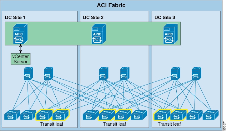
The stretched fabric is a single ACI fabric. The sites are one administration domain and one availability zone. Administrators are able to manage the sites as one entity; configuration changes made on any APIC controller node are applied to devices across the sites. The stretched ACI fabric preserves live VM migration capability across the sites. The ACI stretched fabric design has been validated, and is hence supported, on up to three interconnected sites.
An ACI stretched fabric essentially represents a "stretched pod" extended across different locations. A more solid, resilient (and hence recommended) way to deploy an ACI fabric in a distributed fashion across different locations is offered since ACI release 2.0(1) with the ACI Multi-Pod architecture. For more information, refer to the following white paper:
Stretched Fabric APIC Cluster Guidelines
The ACI fabric recommended minimum APIC cluster size is three nodes, up to a maximum of 31 nodes. In a two-site ACI stretched fabric scenario, provision at least two APIC controller nodes at one site and a third APIC controller node at the second site. Each of the APIC nodes will synchronize across the sites, and will provide all the APIC controller functions to each site. An administrator can log in to any APIC node for configuration or monitoring purposes. In addition to providing policy configuration the APIC controllers also collect event logs and traffic statistics from leaf switches. Place two APIC controllers on the site that has more switches or the site that is considered the main operational site.
State and data are synchronized among all APIC cluster nodes. Latency does play a role in APIC cluster performance. As of the publication of this document, APIC clustering has been validated up to a maximum latency of 50 msec RTT.
Site-to-Site Connectivity Options
ACI stretched fabric site-to-site connectivity options include dark fiber, dense wavelength division multiplexing (DWDM), and Ethernet over MPLS (EoMPLS) pseudowire.
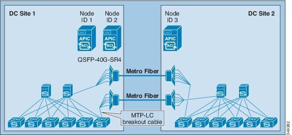
Dark Fiber
In addition to short reach QSFP transceivers, the following long reach QSFP transceivers are supported with ACI fabric software release version 1.0(3f).
|
Cisco QSFP |
Cable Distance |
||
|---|---|---|---|
|
QSFP-40G-LR4 |
10 km |
||
|
QSFP-40GE-LR4 |
10 km |
||
|
QSFP-40GLR4L |
2 km |
||
|
QSFP-40G-ER4 |
30 km
|
For all these transceivers, the wavelength is 1310, the cable type is SMF, and the power consumption is 3.5W.
These optical transceivers enable connecting sites that are up to 30KM apart using dark fiber. Although the standard QSFP-40G-ER4 supports distances up to 40KM, the current ACI software limits it to 30KM.
For deployment scenarios where only 10G connections are available across sites, it is possible to use Cisco QSFP+ to SFP+ Adapter (QSA) modules (CVR-QSFP-SFP10G) on leaf and spine interfaces to convert the interface speed to 10G (from the original 40G/100G). For more information on the support of the QSA adapter for Nexus 9300/9500 switches, refer to the following link:
Dense Wavelength Division Multiplexing
This design has been validated with ACI software version 1.0(3f) to provide connectivity between sites of up to 800KM.
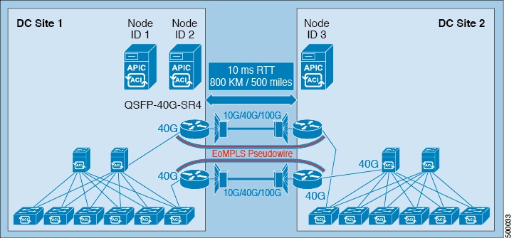
Ethernet Over MPLS Pseudowire
An Ethernet over MPLS (EoMPLS) pseudowire (PW) provides a tunneling mechanism for Ethernet traffic through an MPLS-enabled Layer 3 core network. EoMPLS PWs encapsulate Ethernet protocol data units (PDUs) inside MPLS packets and use label switching to forward them across an MPLS network. The connection between the sites must support link level packet exchanges (such as LLDP) between the leaf and spine switches in the ACI fabric. Layer 2 switches are not a suitable option in this case because they do not support this requirement. An EoMPLS PW can provide connectivity between leaf and spine switches in the stretched fabric when a dedicated 40G long distance DWDM link between two sites is not available. A 40G link could be cost prohibitive, or simply might not be available at all.
no lldp				<== Assure consistent ASR behavior
interface FortyGigE0/2/0/0			<== 40G Facing the fabric
 description To-Spine-2-Eth1/5
 mtu 9216
 load-interval 30
 l2transport				<== Critical command for fast failover
  propagate remote-status
!
l2vpn
 router-id 5.5.5.1
 xconnect group ASR9k_Grp_1
  p2p ASR9k_1_to_4
   interface FortyGigE0/2/0/0
   neighbor ipv4 5.5.5.4 pw-id 104
interface TenGigE0/2/1/0 			<== 10G Towards remote site.
 description To-ASR9k-4
 cdp
 mtu 9216
 service-policy output QoS_Out_to_10G_DCI_Network
 ipv4 address 5.5.2.1 255.255.255.252
 load-interval 30

router ospf 1
 log adjacency changes
 router-id 5.5.5.1
 nsf ietf
 area 0
  interface Loopback0
   passive enable
  !
  interface TenGigE0/2/1/0
   bfd fast-detect			<== BFD for fast detection of DWDM/Indirect failures.
   network point-to-point
   mpls ldp sync
mpls ldp
 log
  hello-adjacency
  graceful-restart
 !
 router-id 5.5.5.1
 interface TenGigE0/2/1/0
An EoMPLS pesudowire link between two sites can be 10G, 40G or 100G. And the long distance DWDM link can be shared with other types of services as well. When there is a low speed link such as a 10G link or the link is shared among multiple use cases, an appropriate QoS policy must be enabled to ensure the protection of critical control traffic. In an ACI stretched fabric design, the most critical traffic is the traffic among the APIC cluster controllers. Also, the control protocol traffic (such as IS-IS or MP-BGP) also needs to be protected. Assign this type of traffic to a priority queue so that it is not impacted when congestion occurs on the long distance DCI link. Assign other types of traffic (such as SPAN) to a lower priority to prevent it crowding out bandwidth from production data traffic.

In the ACI fabric, each 802.1p priority is mapped to certain types of traffic. The following table lists the mapping between data traffic type, 802.1p priority, and QoS-group internal to the leaf and spine switches.
|
Class of Service QoS Group |
Traffic Type |
Dot1p Marking in the VXLAN Header |
|---|---|---|
|
0 |
Level 3 user data |
0 |
|
1 |
Level 2 user data |
1 |
|
2 |
Level 1 user data |
2 |
|
3 |
APIC controller traffic |
3 |
|
4 |
SPAN traffic |
4 |
|
5 |
Control traffic |
5 |
|
5 |
Trace route |
6 |
 Note |
Starting from ACI release 4.0(1), three additional QoS priority levels (4, 5 and 6) are available to classify user traffic. |
class-map match-any SUP_Traffic
 match mpls experimental topmost 5
 match cos 5
 end-class-map
!
class-map match-any SPAN_Traffic
 match mpls experimental topmost 7 4 			<== Span Class + Undefined merged
 match cos 4 7
 end-class-map
!
class-map match-any User_Data_Level_3
 match mpls experimental topmost 1
 match cos 0
 end-class-map
!
class-map match-any User_Data_Level_2
 match mpls experimental topmost 0
 match cos 1
 end-class-map
!
class-map match-any User_Data_Level_1
 match mpls experimental topmost 0
 match cos 2
 end-class-map
!
class-map match-any APIC+Traceroute_Traffic
 match mpls experimental topmost 3 6
 match cos 3 6
 end-class-map
!
policy-map QoS_Out_to_10G_DCI_Network
 class SUP_Traffic
  priority level 1
  police rate percent 15
 class APIC+Traceroute_Traffic
  priority level 2
  police rate percent 15
 class User_Data_Traffic_3
  bandwidth 500 mbps
  queue-limit 40 kbytes
 class User_Data_Traffic_1
  bandwidth 3200 mbps
  queue-limit 40 kbytes
 class User_Data_Traffic_2
  bandwidth 3200 mbps
  queue-limit 40 kbytes
 class SPAN_Traffic
  bandwidth 100 mbps
  queue-limit 40 kbytes
 class class-default

interface TenGigE0/2/1/0
 description To-ASR9k-4
 cdp
 mtu 9216
 service-policy output QoS_Out_to_10G_DCI_Network
 ipv4 address 5.5.2.1 255.255.255.252
 load-interval 30
Transit Leaf Switch Guidelines

When bandwidth between sites is limited, it is preferable to have WAN connectivity at each site. While any leaf can be a transit leaf and a transit leaf can also be a border leaf (as well as provide connectivity for compute or service appliance resources), it is best to separate transit and border leaf functions on separate switches. By doing so, hosts go through a local border leaf to reach the WAN, which avoids burdening long distance inter-site links with WAN traffic. Likewise, when a transit leaf switch needs to use a spine switch for proxy purposes, it will distribute traffic between local and remote spine switches.
MP-BGP Route Reflector Placement
The ACI fabric uses MP-BGP to distribute external routes within ACI fabric. As of ACI software release 1.0(3f), the ACI fabric supports up to two MP-BGP route reflectors. In a stretched fabric implementation, place one route reflector at each site to provide redundancy. For details about MP-BGP and external routes distribution within ACI fabric please refer to following paper: http://www.cisco.com/c/en/us/solutions/collateral/data-center-virtualization/application-centric-infrastructure/white-paper-c07-732033.html
Stretched ACI Fabric Preserves VM Mobility
The stretched ACI fabric behaviors the same way as the regular ACI fabric, supporting full VMM integration. An APIC cluster can interact with a VMM manager for a given distributed virtual switch (DVS). For example, one VMWare vCenter operates across the stretched ACI fabric sites. The ESXi hosts from both sites are managed by the same vCenter and the DVS is stretched to the two sites. The APIC cluster can register and interact with multiple vCenters when multiple DVS are involved.
Each leaf provides distributed anycast gateway functions with the same gateway IP and gateway MAC addresses, so workloads (physical or virtual) can be deployed between sites. Live migration is supported in case of virtual workloads. Each leaf switch provides the optimal forwarding path for intra-subnet bridging and inter-subnet routing.
Failure Scenarios and Operational Guidelines
The ACI switch and APIC controller software recover from various failure scenarios. Follow the guidelines below regarding best operating practices for handling various failure scenarios.
Single Link Failure between Sites
A single inter-site link failure has no impact to the operation of the ACI fabric. The Intermediate System-to-Intermediate System Protocol (IS-IS) protocol within the ACI fabric reacts to the link failure and computes new a forwarding path based on the new topology. As long as there is connectivity between sites, the APIC cluster is maintained and control and data are synchronized among the controller nodes. Best practice is to bring the failed link(s) back up so as to avoid system performance degradation, or to prevent a split fabric scenario from developing.
Loss of a Single APIC Controller
The APIC cluster distributes multiple replicated data records and functions across a federated cluster, providing services to the switching fabric as a single control element. The APIC supports from 3 to 31 nodes in a cluster. The current recommended minimum is a 3-node cluster. If the entire APIC cluster becomes unavailable, the ACI fabric continues to operate normally, except the fabric configuration cannot be modified.
The Cisco APIC cluster uses a technology from large databases called sharding to distribute data among the nodes of the cluster. Data stored in the APIC is portioned to shards. Each shard has three replicas that are stored in the three controller nodes. For each shard, one controller is elected as leader and the rest are followers. Only the leader of the shard can execute write operations to the shard. This mechanism ensures consistency of data and distributes the workload among all controller nodes.
The loss of one APIC controller in either site has no impact on the ACI fabric. With two APIC nodes alive, the cluster still has a quorum (two out of three) and administrators can continue to make configuration changes. There is no configuration data loss due to the APIC node being unavailable. The two APIC nodes retain redundant copies of the APIC data base, and the leadership role for the shards of the lost APIC controller is distributed among the remaining APIC controllers. As is the case with the non-stretched ACI fabric, best practice is to promptly bring the APIC cluster back to full health with all APIC nodes being fully healthy and synchronized.
Refer to the following whitepaper on the APIC cluster architecture for more information on high available design: http://www.cisco.com/c/en/us/solutions/collateral/data-center-virtualization/unified-fabric/white-paper-c11-730021.pdf
Split Fabric
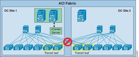
In this situation the split fabrics continue to operate independently. Traffic forwarding is not affected. The two fabrics can learn the new endpoints through the data plane. At the site containing the VMM controller (site 1 in the figure above), endpoints are learned by the control plane as well. Upon learning new endpoints, leaf switches update the spine proxy. Independently of leaf switches, spine switches in each site learn of new endpoints via the co-operative key server (COOP) protocol. After the connections between sites are restored, the spine proxy database from the two sites merge and all spine switches have complete and identical proxy mapping databases.
The split fabric site with two APIC controller nodes (site 1 in the figure above) has quorum (two working nodes out of a cluster of three). The APIC in site 1 can execute policy read and write operations to the fabric. An administrator can log in to either APIC controller node in site 1 and make policy changes. After the link between the two sites recovers, the APIC cluster synchronizes configuration changes across the stretched fabric, pushing configuration changes into the concrete model in all the switches throughout the fabric.
When the connection between two sites is lost, the site with one APIC controller will be in the minority (site 2 in the figure above). When a controller is in the minority, it cannot be the leader for any shards. This limits the controller in site 2 to read only operations; administrators cannot make any configuration changes through the controller in site 2. However, the site 2 fabric still responds to network events such as workload migration, link failure, node failure, or switch reload. When a leaf switch learns a new endpoint, it not only updates the spine proxy via COOP but also sends notifications to controller so that an administrator can view the up-to-date endpoint information from the single controller in site 2. Updating endpoint information on the controller is a write operation. While the links between the two sites are lost, leaf switches in site 2 will try to report the newly learned endpoints to the shard leader (which resides in site 1 and is not reachable). When the links between the two sites are restored, the learned endpoints will be reported to controller successfully.
In short the split brain has no impact to the function of the fabric other than controller in site 2 is in the read only mode.
Stretched Fabric APIC Cluster Recovery Procedures
When a site with one APIC (DC site 2 in the figure below) is unavailable, DC site 1 will not be impacted. You can make fabric-wide policy changes and monitor the entire fabric via the APICs in DC site 1.
However, when a site with two APICs is out of service (DC site 1 in the figure below), you will have read-only access to the fabric via the one APIC running in DC site 2. In this situation, it may take a while to bring the DC site 1 APICs online.
In general, the principle for recovery when one site (DC site 1) fails or is disconnected from another site (DC site 2) is to first try to restore DC site 1 or restore the connectivity between DC site 1 and DC site 2 without any further changes in the fabric. This is the optimal solution to minimize disruptions and avoid potential inconsistencies between DC site 1 and DC site 2.
If this is not possible and you are making configuration changes to the fabric with DC site 2 up but the APICs in DC site 1 out of service, then follow these procedures to enable a standby APIC in DC site 2 temporarily, then restore the full-stretched fabric again afterward.
Note |
This procedure is required only when it is necessary to make configuration changes to the fabric while the DC site 1 APICs are out of service. |
Procedure to Enable a Standby APIC
In the case where a site with two APICs becomes unavailable and needs to be restored, you should have a standby APIC already set up in the second site to successfully recover the stretched fabric APIC cluster, as shown in the following figure. Provisioning a standby APIC for DC site 2 in this case enables making stretch-fabric wide policy changes while the two APICs at DC site 1 are restored.
For more information and instructions on setting up a standby APIC, refer to the following sections in the Cisco APIC Getting Started Guide:
-
"Setup for Active and Standby APIC"
-
"About Cold Standby for a Cisco APIC Cluster"
-
"Verifying Cold Standby Status Using the GUI"
-
"Switching Over Active APIC with Standby APIC Using GUI"
Failover to a Standby APIC When A Site Is Down
Use the following procedure to failover a standby APIC when a site is down. These procedures assume a configuration where two sites are up and a cluster is formed, and a standby APIC is set up in the second site, as described in Procedure to Enable a Standby APIC.
These procedures use the topology presented below, where:
-
The node IDs for the APICs in DC site 1 are node ID 1 and node ID 2
-
The node ID for the APIC in DC site 2 is node ID 3
-
The node ID for the standby APIC in DC site 2 is node ID 21.
Note |
It is critical to perform the steps in the following procedures in the correct order according to the instructions below. |
Procedure
| Step 1 |
When you suspect that the APICs in DC site 1 are down, you must first verify that the DC site 1 APICs are not functional, that the outage is not just due to loss of connectivity between the two sites. When it is clear that the APICs in DC site 1 are down and restoring them will take time, bring up the standby APIC in DC site 2 (node ID 21) using the following steps. |
| Step 2 |
Disable inter-site links between DC site 1 and DC site 2. This prevents the two APICs in DC site 1 from communicating with DC site 2 if they suddenly come online. If the two APICs in DC site 1 come online while the standby APIC comes online in the next step, the cluster will not form normally. |
| Step 3 |
Log in to the node in DC site 2 (node ID 3) and verify the cold standby status for node ID 21.
|
| Step 4 |
Stay logged in to the node in DC site 2 (node ID 3) and switch over the APIC that is down with the standby APIC.
At this point in the process, the nodes are in these states:
|
Restoring a Full Stretched Fabric
Before you begin
The procedures in this section assume that you have already completed the procedures in Failover to a Standby APIC When A Site Is Down.
Procedure
| Step 1 |
Restart all the switch nodes on DC site 1 with the clean option. Significant changes made to the fabric might not be merged with the APICs if DC site 1 were simply brought online. To bring DC site 1 back online without problems, restart all of the nodes in DC site1 in the fabric with configuration wipe options, including the APICs in DC site 1. Log in to each switch with username “admin” and enter the following commands: |
| Step 2 |
Restart the first APIC in DC site 1 (node ID 1) with empty configurations by entering the following commands: |
| Step 3 |
Bring up the inter-site connection between DC site 1 and DC site 2. By bringing up the inter-site links, the APICs in DC site 1 will join the already running fabric on DC site 2 and will restore the state from the APICs on DC site 2. |
| Step 4 |
Log in to node ID 3 in DC site 2 and decommission node ID 1 in DC site 1. |
| Step 5 |
Stay logged in to node ID 3 in DC site 2 and recommission node ID 1 in DC site 1. |
| Step 6 |
Configure the second APIC in DC site 1 (node ID 2) as the new standby APIC and change its ID to node ID 21. At this point in the process, the following nodes are in each DC site:

|
| Step 7 |
Log in to node ID 3 in DC site 2 and verify the cold standby status for node ID 21 in DC site 1.
|
| Step 8 |
Switch over the active APIC with the standby APIC.
At this point in the process, the node that was originally the standby node (was originally node ID 21 in DC site 1) is now active and is now node ID 2 in DC site 1, so that the following nodes are in each DC site:
|
| Step 9 |
Log in to the CIMC of the second APIC in DC site 2 (node ID 2 in DC site 2) and power it on. |
| Step 10 |
Restart the second APIC in DC site 2 (node ID 2 in DC site 2) with empty configurations by entering the following commands: |
| Step 11 |
Configure the second APIC in DC site 2 (node ID 2 in DC site 2) as the new standby APIC. The APICs are now back in their original states:
|
Border Leaf Design Considerations
A border leaf switch is a leaf switch that provides routed connectivity between the ACI fabric and the rest of the datacenter network. Best practice is to use two leaf switches for this purpose. In a stretched fabric, border leaf switches are typically placed in different datacenters to maximize availability if there are outages in one datacenter.
Two important design choices related to border-leaf switch placement in a stretched fabric are the following:
-
The use of one or two border leaf switches per datacenter.
-
The choice between the use of dedicated border leaf switches or the use of border leaf switches for both server connectivity and routed connectivity to an outside network.
The design choice must consider the specific ACI software version and hardware capabilities of the leaf switches.
In ACI, an L3Out provides routed connectivity of VRFs to a network outside the ACI fabric. The stretched-fabric border leaf switch topology you choose relates to the type of ACI L3Out configuration you deploy. Border leaf switches support three types of interfaces to connect to an external router:
-
Layer 3 (routed) interface
-
Sub-interface with IEEE 802.1Q tagging
-
Switched virtual interface (SVI)
When configuring an SVI on an L3Out, you specify a VLAN encapsulation. Specifying the same VLAN encapsulation on multiple border leaf nodes in the same L3Out results in the configuration of an external bridge domain. You can configure static or dynamic routing protocol peering over a vPC for an L3Out connection by specifying the same SVI encapsulation on both vPC peers.
Considerations for Using More Than Two Border Leaf Switches
According to the hardware used for the leaf switches and the software release, one has to consider that having more than two border leaf switches as part of the same L3Out in ACI may have restrictions in the following situations:
-
The L3Out consists of more than two leaf switches with SVI using the same encapsulation (VLAN).
-
The border leaf switches are configured with static routing to the external device.
-
The connectivity from the outside device to the fabric is vPC-based.
This is because traffic may be routed from one datacenter to the local L3Out and then bridged on the external bridge domain to the L3Out in the other datacenter.
In the two topologies below, for connectivity to an external active/standby firewall pair, ACI is configured for static routing. The dotted line identifies the border leaf switches. The first topology, shown in Figure 10, is supported with any version of ACI leaf switches. The second topology, shown in Figure 11, is only supported with Cisco Nexus 9300-EX Cloud Scale or newer leaf switches.

Figure 10 illustrates a topology that works with both first and second-generation ACI leaf switches. The L3out uses the same encapsulation on all the border leaf switches to allow static routing from either border leaf switch to the active firewall. In this diagram, both the split fabric transit function and the border leaf switch function are configured on the same leaf switches, which should be planned according to the guidelines in Transit Leaf Switch Guidelines in this article.
Note |
First-generation ACI leaf switches are: Cisco Nexus 9332PQ Switch Cisco Nexus 9372PX-E Switch Cisco Nexus 9372TX-E Switch Cisco Nexus 9372PX Switch Cisco Nexus 9372TX Switch Cisco Nexus 9396PX Switch Cisco Nexus 9396TX Switch Cisco Nexus 93120TX Switch Cisco Nexus 93128TX Switch |

Figure 11 illustrates a topology that is only supported with Cisco Nexus 9300-EX Cloud Scale or newer leaf switches. In this topology, ACI is configured for static routing to an external active/standby firewall pair. To allow static routing from any border leaf switch to the active firewall, the L3Out uses the same encapsulation on all the border leaf switches.
If the border leaf switches are not Cisco Nexus 9300-EX Cloud Scale or newer, and for topologies consisting of more than two border leaf switches, use dynamic routing and a different VLAN encapsulation per vPC pair on the L3Out SVI.
In Figure 12, there are four border leaf switches, two in each datacenter. There are two L3Outs or a single L3Out that uses different VLAN encapsulations for DC1 and DC2. The L3Out configuration uses dynamic routing with an external device. For this design, there are no specific restrictions related to routing to the outside. This is because with dynamic routing, the fabric routes the traffic to the L3Out that has reachability to the external prefix without the need to perform bridging on an outside bridge domain.
Figure 12 illustrates a topology that is supported with both first and second-generation leaf switches.

Design Considerations for Attaching Endpoints to Border Leaf Switches
Dedicated border leaf switches offer increased availability. As an example, failure scenarios related to routing protocols do not impact server-to-server connectivity and a compute leaf switch failure does not impact outside reachability from another compute leaf switch.
However, for smaller scale datacenters it is sometimes necessary to use border-leaf switches also to connect workloads as depicted in Figure 13.

The recommendations for this design need to take into account the policy-cam filtering optimization called "ingress filtering”, that is controlled by the configurable option "Policy Control Enforcement Direction" in the VRF configuration on the APIC:
The following considerations also apply to this design:
-
For best-practices related to the use of external routers or firewalls connected in vPC mode to the border leaf, please refer to the previous section.
-
This design is fully supported when the leaf switches in DC1 and DC2 are all Cisco Nexus 9300-EX Cloud Scale or newer.
-
If servers are connected to first-generation leaf switches, consider either of the following options:
-
If a VRF ingress policy is enabled (which is the default and the recommended practice), observe these guidelines:
-
Ensure that the software is ACI, Release 2.2(2e) or newer.
-
Configure the option to disable IP endpoint learning on the border leaf switches. You can disable endpoint learning on the border leaf switches by navigating to , by selecting Disable Remote EP Learn.
-
-
Disable ingress filtering on the VRFs that have an L3Out configured. You can perform this configuration by navigating to , by clicking the VRF and selecting Policy Control Enforcement Direction with the option Egress.
Restrictions and Limitations
Take note of the following restrictions and when implementing an ACI stretched fabric:
-
Fabric ARP Flooding in ACI—The ACI fabric handles ARP packets in the following way. For endpoints that the fabric has learned, instead of flooding ARP packets in the bridge domain, the ingress leaf directly sends the ARP packets to the egress leaf. In case of a stretched fabric implementation, when the ingress leaf and egress leaf are at different sites, the direct forwarded ARP packet goes through the transit leaf. Because of a known limitation of the version 1.0(3f) software, the transit leaf will not forward the ARP packets to the egress leaf at the other site. This limitation will be removed in a future release. For now, enable ARP flooding in the bridge domain
-
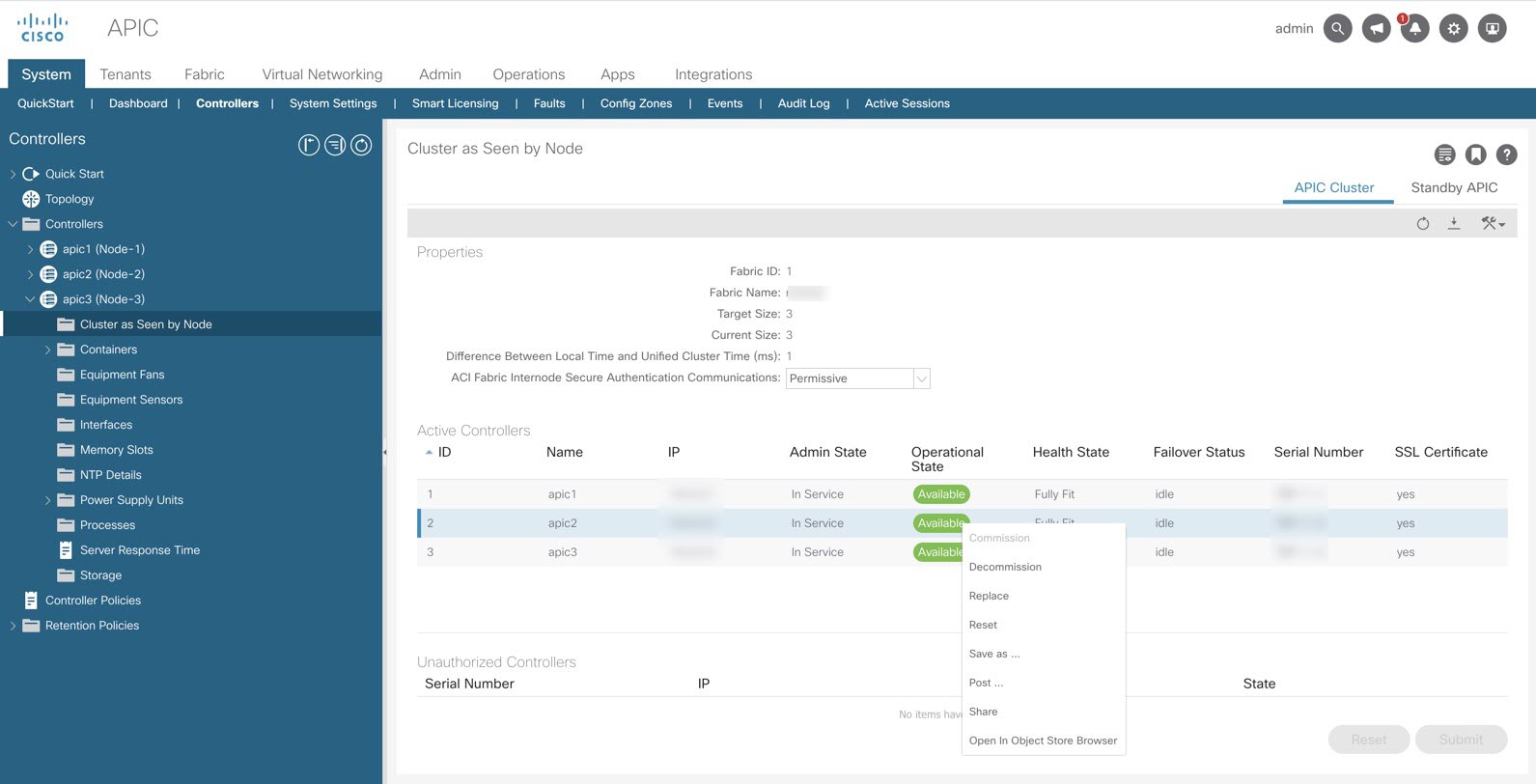
Atomic Counters—Atomic counters can provide traffic statistics and information about packet loss between leaf switches. Cisco documents refer to these types of atomic counters as leaf-to-leaf (or TEP-to-TEP). Leaf-to-leaf atomic counters are enabled by default and the results can be found at this GUI location: Fabric>Fabric Policies>Troubleshooting Policies> Traffic Map. It provides traffic statistics between ACI leaf switches as shown in the following screen capture:
Figure 11. Traffic Map 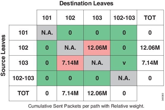
When an ALE based Nexus 9300 series switch is the transit leaf, the leaf-to-leaf atomic counters on transit leaf do not work properly. All other leaf switches that are not transit leafs display correct results for leaf-to-leaf atomic counters. The ALE based Nexus 9300 series transit leaf may count transit traffic (the traffic destined to an egress leaf but using transit leaf as an intermediate hop) as tenant traffic destined to itself. As a result, atomic counters on transit leafs don’t accurately reflect the traffic volume between leaf switches. This constraint only impacts counters while actual data packets are forwarded properly to the egress leaf by the transit leaf.
ALE based Nexus 9300 series includes N9396PX, N9396TX, N93128TX and N93128PX with 12-port GEM N9K-12PQ.
This limitation is addressed with ALE2 based Nexus 9300 series switches. When an ALE2 based Nexus 9300 series switch is the transit leaf, the leaf-to-leaf atomic counters on transit leafs provides proper packets counters and drop counters for traffic between two leaf switches.
ALE2 based Nexus 9300 series includes N9396PX, N9396TX, N93128TX and N93128PX with 6-port GEM N9K-6PQ, N9372TX, N9372PX and N9332PQ.
Atomic counters can also be used to track traffic volume and loss between end points, between EPGs. These types of atomic counters are user configurable. Atomic counters between endpoints work as expected and provide accurate statistics for traffic volume and packet loss between endpoints in a stretched ACI fabric.
Atomic counters between two EPGs work properly if the source and destination EPGs are not present on the transit leaf. An EPG is provisioned on a leaf when one of the following conditions is met:
-
An administrator statically assigns a port (along with VLAN ID) or assigns all ports with a VLAN ID to the EPG with static binding.
-
For an EPG associated with a VMM domain with resolution immediacy set to immediate, the EPG is provisioned on the leaf as soon as the CDP/LLDP discovers a hypervisor is attached to the leaf.
-
For an EPG associated with a VMM domain with the resolution immediacy set to on demand, the EPG is provisioned on the leaf only when a virtual machine is attached to the EPG.
For EPG-EPG atomic counter to work properly, a leaf switch needs to count packets only when EPGs match and only when the traffic is destined to a locally attached endpoint (the destination VTEP of the incoming traffic from a fabric link is the VTEP IP address of the leaf switch).
When either the source or destination EPG is provisioned on the transit leaf, the EPG-EPG atomic counter on the transit leaf increments. The transit leaf also counts the transit traffic when it receives transit traffic (the traffic destined to another leaf but using the transit leaf as and underlay forwarding path) and either the source or destination EPG matches.Figure 12. Stretched Fabric Transit Leaf Atomic Counter Limitation 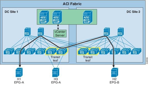
Although the traffic is not terminated locally (destination VTEP doesn’t match the VTEP of the transit leaf) it still counts traffic against the EPG-EPG atomic counter. In this scenario, atomic counters between EPGs are not accurate. As shown in the diagram above, with host H3 attached to a transit leaf and EPG-A enabled on the transit leaf, the atomic counter between EPG-A and EPG-B will not reflect the actual traffic volume between the two EPGs.
-
-
For Stretched Fabric, atomic counters will not work in trail mode, therefore the mode needs to be changed to path mode.
 Feedback