| Step 1 |
In the GUI Navigation pane, under the Tenant Example, navigate
to .
|
| Step 2 |
Right-click and choose Create L3Out.
|
| Step 3 |
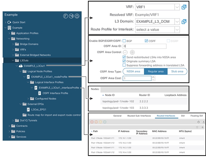
In the Create L3Out screen, Identity tab,
perform the following actions: 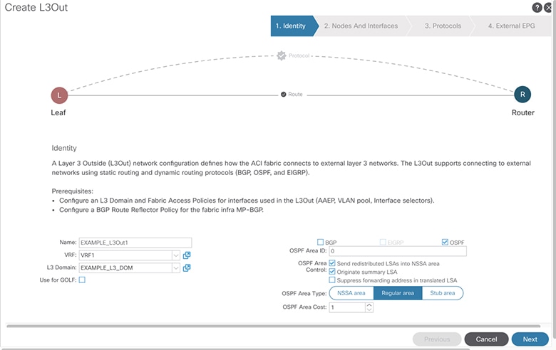
-
In the Name field, enter the name for an L3Out.
(EXAMPLE_L3Out1)
-
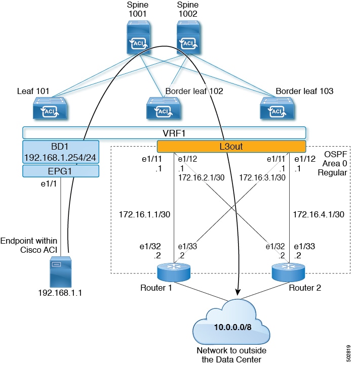
In the VRF field and the L3 Domain
field, choose the appropriate values. (VRF1, EXAMPLE_L3DOM)
-
In the OSPF field, check the checkbox.
-
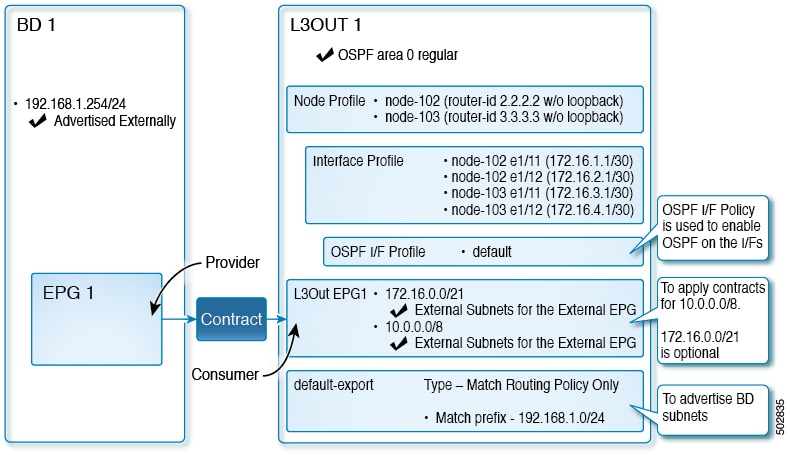
In the OSPF Area ID field, choose the value
0 or the text backbone.
-
In the OSPF Area Type field, choose Regular
area.
-
Keep the rest of the fields with their default values.
|
| Step 4 |
Click Next to display the Nodes and Interfaces screen,
and perform the following actions: 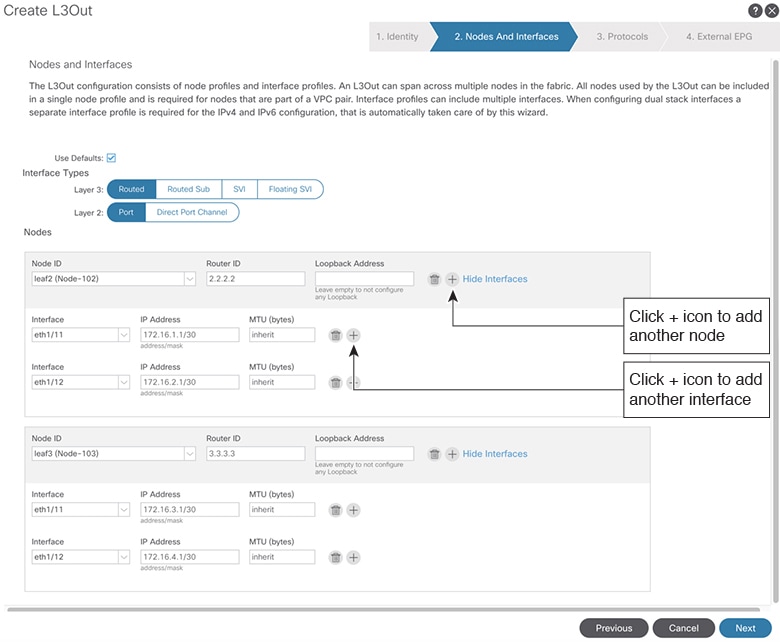
-
In the Interface Types area, in the Layer
3 field and in the Layer 2 field, ensure that
your selections match the choices in the preceding screenshot (Routed and Port).
-
In the Nodes area, in the Node ID
field, from the drop-down list, choose the appropriate node ID. (leaf2 (Node
102))
-
In the Router ID field, enter the appropriate router ID.
(2.2.2.2)
The Loopback Address field auto populates based on the
router ID value you enter. You do not require the loopback address, so delete the
value and leave the field blank.
-
In the Interface field, choose the interface ID.
(eth1/11)
-
In the IP Address field, enter the associated IP address.
(172.16.1.1/30)
-
In the MTU field, keep the default value. (inherit)
-
Click the + icon next to the MTU
field to add an additional interface for node leaf2. (Node-102)
-
In the Interface field, choose the interface ID.
(eth1/12)
-
In the IP Address field, enter the associated IP address.
(172.16.2.1/30)
-
In the MTU field, keep the default value. (inherit)
|
| Step 5 |
To add another node, click the + icon next to the
Loopback Address field, and perform the following actions:
| Note
|
When you click the + icon, the new
Nodes area is displayed below the area that you had populated
earlier.
|
-
In the Nodes area, in the Node ID
field, from the drop-down list, choose the node ID. (leaf3 (Node-103))
-
In the Router ID field, enter the router ID. (3.3.3.3)
The Loopback Address field auto populates based on the
router ID value you enter. You do not require the loopback address, so delete the
value and leave the field blank.
-
In the Interface field, choose the interface ID.
(eth1/11)
-
In the IP Address field, enter the IP address.
(172.16.3.1/30)
-
In the MTU field, keep the default value. (inherit)
-
Click the + icon next to the MTU
field to add an additional interface for node leaf3. (Node-103)
-
In the Interface field, choose the interface ID.
(eth1/12)
-
In the IP Address field, enter the associated IP address.
(172.16.4.1/30)
-
In the MTU field, keep the default value. (inherit), and
click Next.
We have specified the node, interface, and IP address for each interface.
|
| Step 6 |
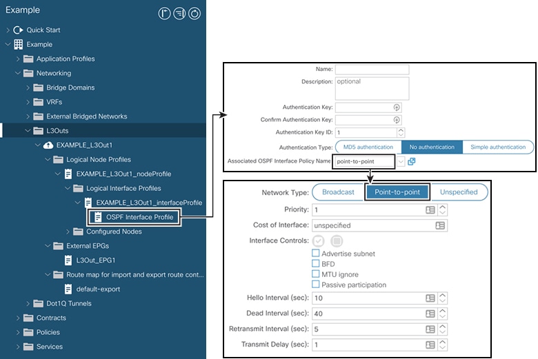
Click Next to view the Protocols screen.
This screen allows you to specify the OSPF interface level policy to configure
hello-interval, network-type, etc. 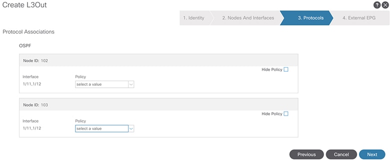
In this example, nothing is selected. Therefore, the default policy is used. The
default OSPF interface profile uses Unspecified as network-type
which defaults to broadcast network type. To optimize this with point-to-point
network-type for sub-interface, see Change the OSPF Interface Level
Parameters (Optional).
|
| Step 7 |
Click Next.
The External EPG screen is displayed with L3Out EPG
details. This configuration is to classify the traffic into the EPG to apply to the
contract.
|
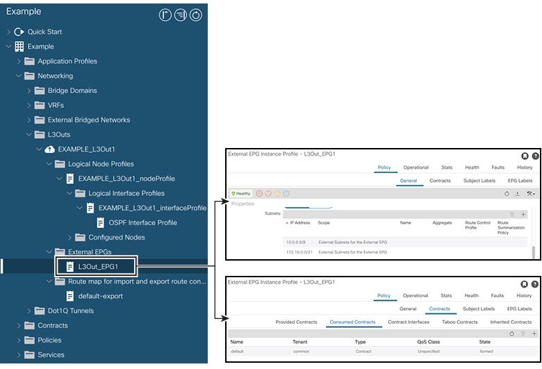
| Step 8 |
In the External EPG screen, perform the following actions:
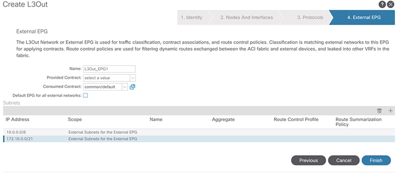
-
In the External EPG area, Name field,
enter a name for the external EPG. (L3Out_EPG1)
-
In the Provided Contract field, do not choose a value.
In this example, there is no provided contract for L3Out_EPG1 because a normal EPG
(EPG1) is the provider.
-
In the Consumed Contract field, choose
default from the drop-down list.
|
| Step 9 |
In the Default EPG for all external networks field, uncheck the
checkbox, and perform the following actions:
-
Click the + icon in the Subnets area,
to display the Create Subnet dialog box.
-
In the IP Address field, enter the subnet.
(10.0.0.0/8)
-
In the External EPG Classification field, check the checkbox
for External Subnets for the External EPG. Click
OK.
|
| Step 10 |
Click the + icon in the Subnets area once
more to display the Create Subnet dialog box, and perform the
following actions:
| Note
|
Although this is an optional configuration, it is a best practice to specify the
L3Out interface subnets in case endpoints have to communicate with those IPs.
|
-
In the IP Address field, enter the subnet.
(172.16.0.0/21)
This subnet covers all the interfaces in the L3Out. This can be each individual
subnet for each routed interface instead.
-
In the External EPG Classification field, check the checkbox
for External Subnets for the External EPG. Click
OK.
-
Click Finish.
|

 Feedback