Cisco Catalyst Blade Switch 3120 for HP Hardware Installation Guide
Bias-Free Language
The documentation set for this product strives to use bias-free language. For the purposes of this documentation set, bias-free is defined as language that does not imply discrimination based on age, disability, gender, racial identity, ethnic identity, sexual orientation, socioeconomic status, and intersectionality. Exceptions may be present in the documentation due to language that is hardcoded in the user interfaces of the product software, language used based on RFP documentation, or language that is used by a referenced third-party product. Learn more about how Cisco is using Inclusive Language.
- Updated:
- February 5, 2008
Chapter: Product Overview
Product Overview
This chapter provides a functional overview of the Cisco Catalyst Blade Switch 3120 for HP, referred to as the switch module. The switch module is installed in the HP c-Class BladeSystem enclosure, referred to as the blade enclosure.
You can connect the uplink ports to other devices such as switches, routers, Cisco Wireless Access Point workstations, Cisco IP phones, or other networking equipment. You can also connect standalone servers or PCs to those ports.
These topics are included:
•![]() Switch Module Features Overview
Switch Module Features Overview
Switch Module Features Overview
The Cisco Catalyst Blade Switch 3120 for HP is a stackable, Layer 3 switch module. The number of ports depends on which modules are installed. See the release notes and the software configuration guide for information about which Layer 3 features are supported. See the "Planning and Creating a Switch Stack" section on page 2-13 for information about stacking the switch.
The Cisco Catalyst Blade Switch 3120 for HP includes a 3120G (CB3120X) and a 3120X (CBS3120X) model. Both are stacking-capable. The initial setup procedure for both models is the same.
Note on WS-CBS3125G-S and WS-CBS3125X-S switch models:
•![]() The WS-CBS3125G-S is the same product as the WS-CBS3120G-S.
The WS-CBS3125G-S is the same product as the WS-CBS3120G-S.
•![]() The WS-CBS3125X-S is the same product as the WS-CBS3120X-S.
The WS-CBS3125X-S is the same product as the WS-CBS3120X-S.
The functionality and the performance of WS-CBS3125 switches are same as those of WS-CBS3120 switches. All Cisco Catalyst Blade Switch 3120/3125 for HP models are HP BladeSystem c-Class compatible.
The CBS3120X switch module supports both the Cisco X2 transceiver modules and the Cisco TwinGig Converter Module. The CBS3120G switch module supports only the Cisco TwinGig Converter Module. See the "10-Gigabit Ethernet Module Slots" section for more information.
For more information about the features of each model, see the hardware installation guide and the software configuration guide for the switch module. See the release notes and the software configuration guide for information about supported Layer 3 features.
See Table 1-1 for more detailed descriptions of the switch module ports.
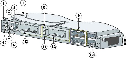
Figure 1-1 shows the Cisco Catalyst Blade Switch 3120 for HP switch module.
Figure 1-1 The Catalyst Blade Switch 3120 for HP
|
|
Switch module |
|
LEDs for ports 19 and 20 or for the Gigabit-Ethernet slot 1 |
|
|
UID1 LED |
|
Gigabit Ethernet uplink ports 23 to 26 and port LEDs |
|
|
Health LEDs |
|
Gigabit Ethernet ports 19 and 20 or 10-Gigabit Ethernet slot 1 |
|
|
System LEDs2 |
|
LEDs for ports 21 and 22 and for the 10-Gigabit Ethernet slot 2 |
|
|
Mode button |
|
Gigabit Ethernet ports 21 and 22 or 10-Gigabit Ethernet slot 2 |
|
|
Console port |
|
StackWise Plus ports |
|
|
Release latch |
1 UID= unit identifier. 2 SYST, STCK, MSTR, MMBR. |
Table 1-1 describes the Cisco Catalyst Blade Switch 3120 for HP ports. Each external port has an associated LED.
|
|
|
|---|---|
Ports 1 to 16 |
Internal Gigabit Ethernet 1000BASE-X downlink ports that connect to the blade enclosure. |
Ports 17 to 18 |
Internal cross-connection ports that you can use to connect to a second switch in the blade enclosure through a backplane connector. You can configure these ports by using the Cisco IOS CLI1 . However, if the blade switches are stacked, these ports are disabled. |
Ports 19 to 22 |
10-Gigabit Ethernet module slots for use with the Cisco TwinGig Converter Modules and Cisco X2 transceiver modules. |
Ports 23 to 26 |
External 10/100/1000BASE-T copper Gigabit Ethernet uplink ports that support auto-MDIX and autonegotiation. |
Internal 100BASE-T Ethernet port |
The Ethernet management port (Fa0) is used only for switch module management traffic, not for data traffic. It is connected to the Onboard Administrator through the blade enclosure backplane connector. Traffic to and from this port is isolated from the switch ports. This port only supports autonegotiation with 100 Mb/s and full-duplex mode. |
StackWise Plus ports |
Stacking cable ports. |
Console port |
Switch module management port (RJ-45 connector). |
1 CLI: command-line interface. |
The switch module is powered from the blade enclosure backplane, and temperature management is provided by the blade enclosure. There is no fan on the switch module.
See the software configuration guide for examples showing how you might deploy the switch module in your network.
Other Features
These sections describe other switch module features:
•![]() 10-Gigabit Ethernet Module Slots
10-Gigabit Ethernet Module Slots
•![]() LEDs
LEDs
Switch Module Console Port
You can connect the switch module through its console port to a PC by using the RJ-45-to-DB9 female cable that ships with the product. If you need a spare cable, you can order a kit (part number ACS-DSBUASYN=) directly from Cisco. If you want to attach the switch module to any other device, such as a terminal server, you might need a different cable. For console port and adapter pinout information, see the "Connector and Cable Specifications" section on page B-1.
10/100/1000 Ports
The 10/100/1000 Ethernet ports use standard RJ-45 connectors with Ethernet pinouts. The maximum cable length is 328 feet (100 meters). The 100BASE-TX and 1000BASE-T traffic requires Category 5, Category 5e, or Category 6 unshielded twisted pair (UTP) cable. The 10BASE-T traffic can use Category 3 or Category 4 UTP cable.
For more information about the 10/100/1000 Ethernet port connections and specifications, see the Connecting to the 10/100/1000 Ports, page 2-22, and Appendix B, "Connector and Cable Specifications."
10-Gigabit Ethernet Module Slots
The 10-Gigabit Ethernet module slots are used for uplink connections to other switches and routers. The module slots operate in full-duplex mode. The CBS3120X uses the hot-swappable Cisco X2 transceiver modules and the Cisco TwinGig Converter Module. The CBS3120G uses only the Cisco TwinGig Converter Module.
These X2 transceiver modules are supported on the CBS3120X switch module:
•![]() CX4
CX4
•![]() LX4
LX4
•![]() SR
SR
•![]() LRM
LRM
For the latest information about the supported X2 transceiver modules, see the switch release notes on Cisco.com at this location:
http://www.cisco.com/en/US/products/ps6748/tsd_products_support_series_home.html
For more information about the 10-Gigabit Ethernet module slots, see the "Installing Devices in the 10-Gigabit Ethernet Slots" section on page 2-17. For cable specifications, see Appendix B, "Connector and Cable Specifications."
Cisco TwinGig Converter Module
The Cisco TwinGig Converter Module (model CVR-X2-SFP), also known as the converter module, has two small form-factor pluggable (SFP) module slots that convert the 10-Gigabit slot into a dual SFP module interface to establish Gigabit uplinks to network devices. The SFP modules have LC connectors for fiber-optic connections or RJ-45 connectors for copper connections. These SFP modules are supported:
•![]() 1000BASE-SX
1000BASE-SX
•![]() 1000BASE-T
1000BASE-T
For more information about the SFP modules, refer to your SFP module documentation. For the latest information about the supported SFP transceiver modules, see the switch release notes on Cisco.com at this location:
http://www.cisco.com/en/US/products/ps6748/tsd_products_support_series_home.html
For more information about the Cisco TwinGig Converter Module, see the "Installing X2 Transceiver Modules and Cisco Converter Modules" section on page 2-18. For cable specifications, see Appendix B, "Connector and Cable Specifications."
LEDs
You can use the switch LEDs to monitor switch module activity and performance. Graphical representations of the LEDs described in these sections are visible in the device manager.

Note ![]() The System LED (SYST), stack LED (STCK), Stack Master LED (MSTR), and Stack Member LED (MMBR) are shown as item 4 in Figure 1-1.
The System LED (SYST), stack LED (STCK), Stack Master LED (MSTR), and Stack Member LED (MMBR) are shown as item 4 in Figure 1-1.
System LED
The System LED (SYST) shows whether the system is receiving power and is functioning properly. Table 1-2 lists the LED colors and their meanings.
Stack LED
To see the status of the StackWise Plus ports, press the Mode button. The Stack LED (STCK) is green when the StackWise Plus ports are up and amber when the ports are down. The bottom two 10-Gigabit Ethernet module slot LEDs show the status for StackWise Plus ports 1 and 2, respectively (see item 11 in Figure 1-1).
When in stack mode, if both 10-Gigabit Ethernet uplink port LEDs are green, the stack is operating at full bandwidth. If one or both of the 10-Gigabit uplink LEDs are not green, the stack is not operating at full bandwidth.
See the "LED Behavior in Stack Mode" section for more information.
Stack Master LED
The Stack Master LED (MSTR) shows the stack master status. Table 1-3 lists the LED colors and their meanings.
Stack Member LED
The Stack Member LED (MMBR) shows the switch stack membership number, which ranges from 1 to 9. The Stack Member LED blinks a number of times equal to the membership number of the switch, pauses, and then repeats the process until you turn off stack mode or until stack mode times out.
Table 1-4 lists the LED colors and their meanings when stack mode is on. When stack mode is off, the Member LED is off.
UID and Health LEDs
The UID and Health LEDs are controlled by the blade enclosure software (Onboard Administrator). The UID LED is on when the switch module is identified by the blade enclosure. The Health LED is green during normal operation; it is amber when a failure is detected.
RJ-45 Uplink Port LEDs
The external 10/100/1000BASE-T copper Gigabit Ethernet uplink port LEDs display link and activity information about each individual port. These LEDs are on the top left and right, respectively, of each RJ-45 port (see item 9 in Figure 1-1). Table 1-5 describes the port link LED colors and their meanings.
|
|
|
|---|---|
Off |
No link established. |
Solid green |
Link established, no activity. |
Blinking green |
Traffic on an established link. |
Amber |
Port disabled, either error or STP1 disabled. |
Alternating Green/Amber |
Link fault. |
1 STP: Spanning Tree Protocol. |
The port activity LED blinks green to indicate traffic.
10-Gigabit Ethernet Module Slot Port LEDs
The behavior of the 10-Gigabit Ethernet module slot port LEDs depends on whether an X2 module or a converter module is installed and whether you pressed the Mode button to place the switch module in stack mode.
X2 Module Installed (Only the CBS3120X Switch)
The 10-Gigabit Ethernet module slot LEDs 19 to 22 show the status for ports 19 to 20 and 21 to 22, respectively (see items 8 and 11 in Figure 1-1). When an X2 module is installed, each pair of LEDs behaves as one. The top pair of LEDs represents the left X2 module in slot 19 to 20, and the bottom pair of LEDs represents the right X2 module in slot 21 to 22.
Table 1-6 describes the 10-Gigabit Ethernet slot port LED colors and their meanings.
Converter Module Installed
When a converter module is in one of the 10-Gigabit Ethernet module slots, the LEDs show the status of the SFP modules that are in the converter module. If one converter module is installed in slots 19 and 20, and one converter module is installed in slots 20 and 21, this is how the LEDs correspond to the installed SFP modules:
1. ![]() The top LED (19) corresponds to the SFP module in slot 19.
The top LED (19) corresponds to the SFP module in slot 19.
2. ![]() The second LED (20) corresponds to the SFP module in slot 20.
The second LED (20) corresponds to the SFP module in slot 20.
3. ![]() The third LED (21) corresponds to the SFP module in slot 21.
The third LED (21) corresponds to the SFP module in slot 21.
4. ![]() The fourth LED (22) corresponds to the SFP module in slot 22.
The fourth LED (22) corresponds to the SFP module in slot 22.
See Table 1-6 for a description of the 10-Gigabit Ethernet slot port LED colors and their meanings.
LED Behavior in Stack Mode
Whether an X2 module or a converter module is installed in the 10-Gigabit Ethernet module slots, the two bottom LEDs (21 and 22) show the status of the StackWise Plus ports 1 and 2, respectively. The top two LEDs (19 and 20) are off when in stack mode. Table 1-7 describes the LED colors in stack mode and their meanings.
StackWise Plus Ports
The switch module ships with a 1-meter StackWise cable that you can use to connect the StackWise Plus ports.

You can order these StackWise Plus cables from your Cisco sales representative:
•![]() CAB-STK-E-0.5M= (0.5-meter cable)
CAB-STK-E-0.5M= (0.5-meter cable)
•![]() CAB-STK-E-1M= (1-meter cable)
CAB-STK-E-1M= (1-meter cable)
•![]() CAB-STK-E-3M= (3-meter cable)
CAB-STK-E-3M= (3-meter cable)
Power Connectors
The blade enclosure controls power to the switch module. After the blade enclosure detects the presence of the switch module, it moves the switch module to the full power state. The switch module software is not involved in power control functions.
Management Options
This section describes management options for the switch module:
•![]() Using the Command-Line Interface
Using the Command-Line Interface
•![]() Using the Onboard Administrator CLI and GUI
Using the Onboard Administrator CLI and GUI
Using the Device Manager
The simplest way to manage the switch module is by using the device manager that is in the switch module memory. This is a web interface that offers quick configuration and monitoring. You can access the device manager from anywhere in your network through a web browser.
Follow these steps:
1. ![]() Launch a web browser on your PC or workstation.
Launch a web browser on your PC or workstation.
2. ![]() Enter the switch module IP address in the web browser, and press Enter. The device manager page appears. (See Figure 1-2.)
Enter the switch module IP address in the web browser, and press Enter. The device manager page appears. (See Figure 1-2.)
Figure 1-2 Device Manager Page
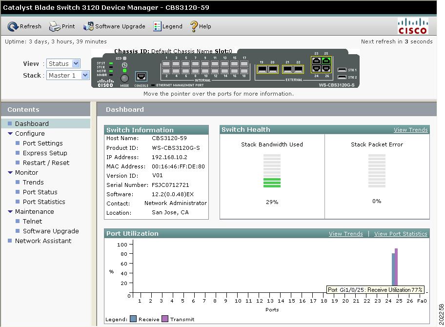
3. ![]() Use the device manager to perform basic switch module configuration and monitoring. Refer to the device manager online help for more information.
Use the device manager to perform basic switch module configuration and monitoring. Refer to the device manager online help for more information.
4. ![]() For more advanced configuration, download and run the Cisco Network Assistant, which is described in the next section.
For more advanced configuration, download and run the Cisco Network Assistant, which is described in the next section.
Using the Command-Line Interface
The switch module CLI is based on Cisco IOS software and enhanced to support desktop-switching features. You can fully configure and monitor the switch module from the CLI. You can access the CLI either by connecting your management station directly to the switch module console port or by using Telnet from a remote management station. Refer to the switch module command reference on Cisco.com for more information.
For quick setup instructions that use the CLI, go to Appendix C, "Configuring the Switch with the CLI-Based Setup Program."
Using the Onboard Administrator CLI and GUI
See the HP BladeSystem enclosure setup and installation guide at http://www.hp.com/go/bladesystem/documentation for information on how to use the Onboard Administrator CLI and GUI.
Other Management Options
You can use SNMP management applications such as CiscoWorks Small Network Management Solution (SNMS) to configure and manage the switch module. You also can manage it from an SNMP-compatible workstation that is running platforms such as HP OpenView or SunNet Manager.
Network Configurations
Refer to the switch module software configuration guide on Cisco.com for an explanation of network configuration concepts. The software configuration guide also provides examples of network configurations that use the switch module to create dedicated network segments that are interconnected through Gigabit Ethernet connections.
 Feedback