Cisco Catalyst Blade Switch 3120 for HP Hardware Installation Guide
Bias-Free Language
The documentation set for this product strives to use bias-free language. For the purposes of this documentation set, bias-free is defined as language that does not imply discrimination based on age, disability, gender, racial identity, ethnic identity, sexual orientation, socioeconomic status, and intersectionality. Exceptions may be present in the documentation due to language that is hardcoded in the user interfaces of the product software, language used based on RFP documentation, or language that is used by a referenced third-party product. Learn more about how Cisco is using Inclusive Language.
- Updated:
- February 5, 2008
Chapter: Connector and Cable Specifications
Connector and Cable Specifications
This appendix describes the cables and adapters that you use to connect that you use to connect the switch module to other devices. This appendix includes these sections:
•![]() Cable and Adapter Specifications
Cable and Adapter Specifications
Connector Specifications
These sections describe the connectors used with the switch:
•![]() 10-Gigabit Ethernet Module Interfaces
10-Gigabit Ethernet Module Interfaces
•![]() Cisco TwinGig Converter Module Ports
Cisco TwinGig Converter Module Ports
10/100/1000 Ports
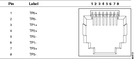
The 10/100/1000 Ethernet ports on the switch module use standard RJ-45 connectors. Figure B-1 shows the pinout.

Note ![]() You can use the mdix auto interface configuration command in the CLI to enable the automatic medium-dependent interface crossover (auto-MDIX) feature. When the auto-MDIX feature is enabled, the switch module detects the required cable type for copper Ethernet connections and configures the interfaces accordingly. Therefore, you can use either a crossover or a straight-through cable for connections to a copper 10/100/1000 or 1000BASE-T SFP module port on the switch module, regardless of the type of device on the other end of the connection.
You can use the mdix auto interface configuration command in the CLI to enable the automatic medium-dependent interface crossover (auto-MDIX) feature. When the auto-MDIX feature is enabled, the switch module detects the required cable type for copper Ethernet connections and configures the interfaces accordingly. Therefore, you can use either a crossover or a straight-through cable for connections to a copper 10/100/1000 or 1000BASE-T SFP module port on the switch module, regardless of the type of device on the other end of the connection.
For configuration information for this feature, refer to the switch module software configuration guide or the switch module command reference.
Connecting to 10BASE-T- and 100BASE-TX-Compatible Devices
When connecting the ports to 10BASE-T- and 100BASE-TX-compatible devices, such as servers, workstations, and routers, you can use a two or four twisted-pair, straight-through cable wired for 10BASE-T and 100BASE-TX. Figure B-6 shows the two twisted-pair, straight-through cable schematics. Figure B-8 shows the four twisted-pair, straight-through cable schematics.
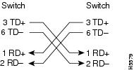
When connecting the ports to 10BASE-T- and 100BASE-TX-compatible devices, such as switches or repeaters, you can use a two or four twisted-pair, crossover cable. Figure B-7 shows the two twisted-pair, crossover cable schematics. Figure B-9 shows the four twisted-pair, crossover cable schematics.
You can use Category 3, 4, or 5 cabling when connecting to 10BASE-T-compatible devices. You must use Category 5 cabling when connecting to 100BASE-TX-compatible devices.
Connecting to 1000BASE-T Devices
When connecting the ports to 1000BASE-T devices, such as servers, workstations, and routers, you must use a four twisted-pair, Category 5, straight-through cable wired for 10BASE-T, 100BASE-TX, and 1000BASE-T. Figure B-8 shows the straight-through cable schematics.
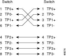
When connecting the ports to other devices, such as switches or repeaters, you must use a four twisted-pair, Category 5, crossover cable. Figure B-9 shows the crossover cable schematics.
Note ![]() Be sure to use a four twisted-pair, Category 5 cable when connecting to a 1000BASE-T-compatible device.
Be sure to use a four twisted-pair, Category 5 cable when connecting to a 1000BASE-T-compatible device.
Note ![]() Use a straight-through cable to connect two ports only when one port is designated with an X. Use a crossover cable to connect two ports when both ports are designated with an X or when both ports do not have an X.
Use a straight-through cable to connect two ports only when one port is designated with an X. Use a crossover cable to connect two ports when both ports are designated with an X or when both ports do not have an X.
Figure B-1 10/100/1000 Port Pinouts
10-Gigabit Ethernet Module Interfaces
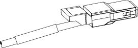
The 10-Gigabit Ethernet modules use SC connectors or Infiniband 4x connectors, as shown in Figure B-2 and Figure B-3.
Figure B-2 10-Gigabit Ethernet Optical Module SC Connector
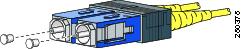
Figure B-3 10-Gigabit Ethernet Infiniband 4x Connector
Cisco TwinGig Converter Module Ports
The Cisco TwinGig Converter Module uses SFP modules for fiber-optic and copper uplink ports. Figure B-4 and Figure B-5 show the SFP module connectors.
Figure B-4 Duplex LC Cable Connector
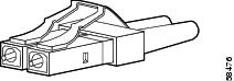
Figure B-5 Copper SFP Module RJ-45 Connector
Console Port
The console port uses an 8-pin RJ-45 connector, which is described in Table B-4 and Table B-5. The supplied RJ-45-to-DB-9 adapter cable is used to connect the console port of the switch module to a console PC. You need to provide a RJ-45-to-DB-25 female DTE adapter if you want to connect the switch module console port to a terminal. You can order a kit (part number ACS-DSBUASYN=) containing that adapter from Cisco. For console port and adapter pinout information, see Table B-4 and Table B-5.
Cable and Adapter Specifications
These sections describe the cables and adapters used with the switch module.
•![]() 10-Gigabit Ethernet X2 Transceiver Module Cable Specifications
10-Gigabit Ethernet X2 Transceiver Module Cable Specifications
•![]() SFP Module Cable Specifications
SFP Module Cable Specifications
•![]() Two Twisted-Pair Cable Pinouts
Two Twisted-Pair Cable Pinouts
•![]() Four Twisted-Pair Cable Pinouts for 1000BASE-T Ports
Four Twisted-Pair Cable Pinouts for 1000BASE-T Ports
•![]() Identifying a Crossover Cable
Identifying a Crossover Cable
10-Gigabit Ethernet X2 Transceiver Module Cable Specifications
Table B-1 lists the port cabling specifications for the 10-Gigabit Ethernet X2 transceiver modules. Each port must match the wave-length specifications on the other end of the cable, and for reliable communications, the cable must not exceed the stipulated cable length. Table B-2 lists the transceiver optical send and receive specifications.
|
|
|
|
|
|
|
|---|---|---|---|---|---|
X2-10GB-SR |
850 |
MMF |
62.5 |
160 |
85 feet (26 m) |
X2-10GB-LX4 |
1310 |
MMF1 |
62.5 |
500 |
984 feet (300 m) |
X2-10GB-CX4 |
— |
InfiniBand |
— |
— |
49 feet (15 m) |
X2-10GB-LRM |
1310 |
MMF |
62.5 62.5 50.0 50.0 50.0 |
160 200 400 500 1500 |
220 m (722 feet) 220 m (722 feet) 220 m (722 feet) 220 m (722 feet) 220 m (722 feet) |
1 Mode conditioning patch cord is recommended for MMF applications. |
|
|
|
|
|
|
|---|---|---|---|---|
X2-10GB-SR |
10GBASE-SR, 850-nm MMF |
-11 (max) |
-1.0 (max) |
840 to 860 |
X2-10GB-LX4 |
10GBASE-LX4 WWWDM 1300-nm MMF |
-0.5 per lane (max) |
-0.5 (max) |
Four lanes; overall range: 1269 to 1356 |
X2-10GB-LRM |
10GBASE-LR, 1310-nm MMF |
0.5 (max) -6.5 (min) |
0.5 (max) -8.4 (min average) and -6.4 (min in OMA) |
1260 to 1355 |
1 The launch power shall be the lesser of the Class 1 safety limit or the maximum receive power. Class 1 laser requirements are defined by IEC 60825-1: 2001. |
SFP Module Cable Specifications
Table B-3 lists the cable specifications for the fiber-optic SFP module connections. Each port must match the wave-length specifications on the other end of the cable, and for reliable communications, the cable must not exceed the required cable length. Copper 1000BASE-T SFP transceivers use standard four twisted-pair, Category 5 (or greater) cable at lengths up to 328 feet (100 meters).
|
|
|
|
|
|
|
|---|---|---|---|---|---|
1000BASE-SX |
850 |
MMF |
62.5/125 |
160 |
722 feet (220 m) |
1000BASE-T (GLC-T) |
N/A |
1 Modal bandwidth applies only to multimode fiber. |
Two Twisted-Pair Cable Pinouts
Figure B-6 and Figure B-7 show the schematics of two twisted-pair cables for connecting to 10BASE-T- and 100BASE-TX-compatible devices.
Figure B-6 Two Twisted-Pair Straight-Through Cable Schematic
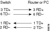
Figure B-7 Two Twisted-Pair Crossover Cable Schematic
Four Twisted-Pair Cable Pinouts for 1000BASE-T Ports
Figure B-8 and Figure B-9 show the schematics of four twisted-pair cables for 10/100/1000 ports on the switch module.
Figure B-8 Four Twisted-Pair Straight-Through Cable Schematic for 10/100/1000 Ports
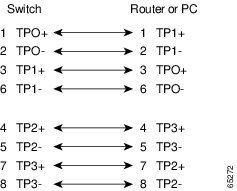
Figure B-9 Four Twisted-Pair Crossover Cable Schematics for 10/100/1000 Ports
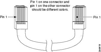
Identifying a Crossover Cable
To identify a crossover cable, compare the two modular ends of the cable. Hold the cable ends side-by-side, with the tab at the back. The wire connected to the pin on the outside of the left plug should be a different color from the wire connected to the pin on the inside of the right plug. (See Figure B-10.)
Figure B-10 Identifying a Crossover Cable
Console Port Adapter Pinouts
Table B-4 lists the pinouts for the console port, the RJ-45-to-DB-9 adapter cable, and the console device.
Table B-5 lists the pinouts for the console port, RJ-45-to-DB-25 female DTE adapter, and the console device.
Note ![]() The RJ-45-to-DB-25 female DTE adapter is not supplied with the switch module. You can order a kit (part number ACS-DSBUASYN=) containing this adapter from Cisco.
The RJ-45-to-DB-25 female DTE adapter is not supplied with the switch module. You can order a kit (part number ACS-DSBUASYN=) containing this adapter from Cisco.
 Feedback