-
null
- Cisco Digital Building Solution Overview
- Cisco POE Switches for the Digital Building Solution
- Power Management
Cisco Digital Building Solution Partner Guide
This document is intended to serve as a starter guide for potential or existing partners who are interested in joining the Digital Building Solution ecosystem and developing Power over Ethernet (POE)-enabled endpoint devices. Armed with this document, along with appropriate equipment (such as the Cisco POE Switch), a partner should have all the tools and information required to take the first step towards enabling network-powered endpoint devices.
This document use lighting devices as example. However, the general methodology is applicable to any network-powered devices.
The following topics are discussed:
■![]() Cisco Digital Building Solution Overview
Cisco Digital Building Solution Overview
■![]() Power Allocation Process between Powered Devices (PDs) and Power Sourcing Equipment (PSE) in the Cisco Digital Building Solution.
Power Allocation Process between Powered Devices (PDs) and Power Sourcing Equipment (PSE) in the Cisco Digital Building Solution.
■![]() Link Layer Discovery Protocol (LLDP) extension for Light Device Classification and Auto Smartports
Link Layer Discovery Protocol (LLDP) extension for Light Device Classification and Auto Smartports
■![]() Constrained Application Protocol (CoAP) Support and Information Model
Constrained Application Protocol (CoAP) Support and Information Model
Cisco Digital Building Solution Overview
The Cisco Digital Building Solution has three major components using lighting devices as example of endpoint devices:
■![]() IP-based light devices, which are often integrated with various sensors
IP-based light devices, which are often integrated with various sensors
■![]() POE switches, which provide power to light devices and provide network function in the lighting network
POE switches, which provide power to light devices and provide network function in the lighting network
■![]() Lighting management software, which offers energy management, and other building management integration
Lighting management software, which offers energy management, and other building management integration
The Digital Building Solution reference architecture, which is depicted in Figure 1, is integrated within an enterprise's campus network. In some cases, the lighting network can be a standalone network without campus network integration.
Figure 1 Digital Building Solution Reference Architecture
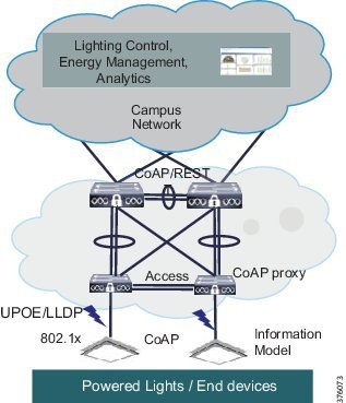
■![]() Constrained Application Protocol (CoAP) leveraged for lighting endpoints:
Constrained Application Protocol (CoAP) leveraged for lighting endpoints:
–![]() Is lightweight, runs over UDP, and is ideal for constrained devices
Is lightweight, runs over UDP, and is ideal for constrained devices
–![]() Conforms to IETF Standard (RFC 7252)
Conforms to IETF Standard (RFC 7252)
–![]() Has many open source implementations for multiple platforms and languages
Has many open source implementations for multiple platforms and languages
–![]() Interoperability among lights from different lighting vendors
Interoperability among lights from different lighting vendors
■![]() The customer deployment scenarios can be categorized into two scenarios:
The customer deployment scenarios can be categorized into two scenarios:
–![]() Centralized Deployment—The light devices are aggregated to POE switches in Intermediate Distribution Frame (IDF) closets in the building. The POE switches that are supported in this deployment scenario are the Cisco Catalyst 4500, Cisco Catalyst 3850, and Cisco Catalyst 3650 switches.
Centralized Deployment—The light devices are aggregated to POE switches in Intermediate Distribution Frame (IDF) closets in the building. The POE switches that are supported in this deployment scenario are the Cisco Catalyst 4500, Cisco Catalyst 3850, and Cisco Catalyst 3650 switches.
–![]() Distributed Deployment—The light devices are connected to POE switches on the ceiling. The POE switches that are supported in this deployment scenario are the Cisco Catalyst Digital Building (CDB) Series Switches.
Distributed Deployment—The light devices are connected to POE switches on the ceiling. The POE switches that are supported in this deployment scenario are the Cisco Catalyst Digital Building (CDB) Series Switches.
Cisco POE Switches for the Digital Building Solution
The primary focus of this section is to provide detailed information about the POE switch component of the solution. This will arm lighting partners with all the information required to understand interoperability and to begin leveraging the POE switch to build network-powered lighting devices.
Table 1 shows the POE switch models that support the Digital Building Solution.
Figure 2 POE Switches Functionality
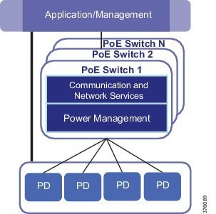
As shown in Figure 2, the POE switch provides the following functionality:
–![]() Provides required power to PDs based on device requirements:
Provides required power to PDs based on device requirements:
–![]() Provides power in constant mode with minimum downtime:
Provides power in constant mode with minimum downtime:
Detailed functionality information is discussed in the following sections.
Power Management
This section includes the following major topics:
■![]() IEEE 802.3af (POE) and IEEE 802.3at (POE+) Standards
IEEE 802.3af (POE) and IEEE 802.3at (POE+) Standards
■![]() Cisco UPOE and IEEE 802.3bt Standard
Cisco UPOE and IEEE 802.3bt Standard
■![]() Link Layer Discovery Protocol
Link Layer Discovery Protocol
■![]() POE Switch Features for Digital Building Solution
POE Switch Features for Digital Building Solution
The POE switch in the Cisco Digital Building Solution is the Power Sourcing Equipment (PSE). This provides power to lighting endpoint devices, which are the Powered Devices (PDs). The lighting endpoint devices obtain necessary power either by a physical layer event classification using electrical signal or by LLDP protocol negotiation.
IEEE 802.3af (POE) and IEEE 802.3at (POE+) Standards
Powered devices have a power limit of 12.95W under the IEEE 802.3af standard established in early 2000. However, as POE devices grow in the marketplace, the power allocations allowed by that standard are proving to be inadequate. In 2009, the IEEE 802.3at standard (also known as POE+, 2009) was established that allocated 25.5W for POE while maintaining backwards compatibility with the existing IEEE 802.3af standard.
PDs and PSEs are distinguished as Type-1 devices complying with the IEEE 802.3af power levels and Type-2 complying with the IEEE 802.at power levels.
Table 2 describes the device classification based on the power requirements defined by IEEE 802.3 standard.
Classification is a method that provides more efficient power allocation by allowing the PSE to identify a PD power classification. Classification information defined by the IEEE specification is as follows:
■![]() Class 0—For PDs that don't support classification
Class 0—For PDs that don't support classification
■![]() Class 1-3—Partitions the PDs into three distinct power ranges
Class 1-3—Partitions the PDs into three distinct power ranges
■![]() Class 4—Includes the new power range defined in IEEE 802.3at
Class 4—Includes the new power range defined in IEEE 802.3at
The IEEE 802.3at standard was also enhanced with a new method of acquiring power classification from a PD and communicating the presence of a Type-2 PSE. This new method is called 2-event classification. For more detail, see Power Allocation Process.
Cisco UPOE and IEEE 802.3bt Standard
In recent years, the enterprise workspace has continued to evolve with increasing numbers of building devices and workloads converging onto the IP network. This has fueled increasing demand for POE to support newer devices, as well as for devices with greater power requirements.
Cisco led the market when it released Universal POE (UPOE) technology in 2011 that provides 60W power per switch port, which enables new deployment options for many more devices, including LED lighting fixtures. See Figure 3.
Figure 3 UPOE Cabling Architecture
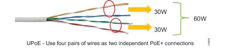
Table 3 describes the IEEE POE standards.
| No impact to network performance of 10/100/1000 Mbps links to the PD |
|||
As defined in IEEE 802.3af and IEEE 802.3at:
■![]() POE delivers electrical power over two pairs of the four twisted pairs of Ethernet cable, such as Cat5E or better.
POE delivers electrical power over two pairs of the four twisted pairs of Ethernet cable, such as Cat5E or better.
■![]() UPOE uses the same cabling standard, but delivers power over all four pairs of wires to achieve 60W output.
UPOE uses the same cabling standard, but delivers power over all four pairs of wires to achieve 60W output.
A new LLDP TLV, 4-wire Power-via-MDI TLV, was introduced for UPOE power negotiation. The PD can use this TLV to advertise its 4-pair-related capabilities and requirements, and the PSE with UPOE support can allocate the power to the PD accordingly.
PoE power allocation beyond 30 watts by IEEE standard is currently undergoing standardization by the IEEE 802.3bt Power over Ethernet Task Force. The ability to deliver higher power (up to 90 watts) to end devices will greatly expand the POE's application base.
Power Allocation Process
This section describes how devices obtain their required power from the POE switch.
Type-1 PDs have a maximum wattage requirement of 12.95W. A PSE powers up a Type-1 PD via 1-event classification at the physical layer by recognizing the classification signature of the PD.
The IEEE 802.3at defines a Type-2 PSE as having the option of acquiring PD power classification by performing 2-event classification or by communicating with the PD over the data link layer via LLDP. The IEEE 802.3at requires that the PD support both methods for power allocations.
Communication methods between a Type-2 PD and a PSE that can be either a Type-1 or a Type-2 device include the following:
■![]() 2-Event Classification (Physical Layer)—The PSE (a Type-2 device) emits 2-event classification pulses to detect the PD. The PD supports IEEE P802.3at and requires more than 12.95W sends a class-4 signature to the PSE.
2-Event Classification (Physical Layer)—The PSE (a Type-2 device) emits 2-event classification pulses to detect the PD. The PD supports IEEE P802.3at and requires more than 12.95W sends a class-4 signature to the PSE.
■![]() Data Link Layer Classification—The PSE (a Type-1 device) emits a 1-event classification pulse and provides power to the PD. The PD can then begin communicating to the PSE using LLDP protocol.
Data Link Layer Classification—The PSE (a Type-1 device) emits a 1-event classification pulse and provides power to the PD. The PD can then begin communicating to the PSE using LLDP protocol.
For PDs requiring power beyond 30 watts, both the PSE and PD need to advertise their support of 4-pair POE to each other. First, the PD asks the PSE to send 30 watts on one pair of wire and then the PD negotiates power beyond 30 watts by utilizing the 4-wire Power-via-MDI LLDP TLV extension for UPOE.
Link Layer Discovery Protocol
In addition to supporting power allocation functionality, the Link Layer Discovery Protocol (LLDP) protocol allows PDs to provide other information to the POE switch to advertise device capabilities and information about the device itself.
This section, which discusses LLDP and LLDP-MED, explores the LLDP extension for use cases in the Cisco Digital Building Solution.
The LLDP is an IEEE 802.1AB standard designed to provide a multi-vendor solution for both discovery of elements on a data network and how they are connected to one other. LLDP-capable devices periodically transmit information in messages called TLV fields to neighboring devices. This information includes chassis and port identification, system name, system capabilities, system description, and other attributes.
The information distributed via LLDP is usually stored by its recipients in a standard Management Information Base (MIB), making it possible for the information to be accessed by a Network Management System (NMS) using a management protocol such as the Simple Network Management Protocol (SNMP). Figure 4 shows the LLDP Frame format.
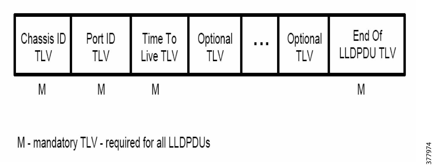
The LLDP standard defines a set of officially recognized optional TLVs. These TLVs provide various details about the LLDP agent advertising them. The LLDP agent can advertise one or more of these TLVs in addition to the mandatory TLVs:
Link Layer Discovery Protocol-Media Endpoint Discovery
The Link Layer Discovery Protocol-Media Endpoint Discovery (LLDP-MED), which is based on the IEEE 802.1AB standard LLDP protocol, was extended to support Voice over IP (VoIP) endpoints. The LLDP-MED extension was defined by the Telecommunications Industry Association (TIA) TR-41.4 subcommittee and approved in April 2006.
LLDP-MED is specified to operate only between endpoint devices such as IP phones and network connectivity devices such as switches.
The new TLV message extensions provide detailed information on POE, network policy, and media endpoint location for Emergency Call Services and inventory management. Further, LLDP-MED provides a fast start behavior, which is very important for both IP telephony and Cisco Digital solutions. This means that at startup the endpoints will initially advertise at a faster rate for a limited time to quickly learn information.
Figure 5 shows the LLDP-MED frame.
Figure 5 LLDP-MED Frame Format
The LLDM-MED Capabilities field can be set to indicate one of the capabilities described in the following sections.
LLDP-MED Extended Power via MDI Discovery
The Power over Ethernet Management TLV allows endpoints to advertise their required power level and power priority, and network connectivity devices to advertise how much power they can supply. These advertisements facilitate power management capability on the switch to allocate power based on demand, priority, and availability.
LLDP-MED Network Policy Discovery
The Network Policy Discovery TLV simplifies deployment of large multi-vendor networks and aids in troubleshooting. This TLV lets endpoints and switches advertise their virtual LAN ID, IEEE Priority, and Differentiated Services Code Point (DSCP) assignments to each other. Network administrators can quickly locate incorrectly configured endpoints.
LLDP-MED Inventory Management Discovery
LLDP-MED's Inventory Management Discovery TLV lets an endpoint transmit detailed inventory information about itself to the switch to which it is attached. This information can include vendor name, model number, firmware revision, and serial number. When a switch receives this information, it will be stored and made accessible to the network management system for inventory reporting.
LLDP-MED Location Identification Discovery
The LLDP-MED's Endpoint Location Discovery TLV was designed for a method to enable E911 within enterprise networks. The TLV contains information related to the telephony wire map of the campus or other attributes that allow for the resolution of the endpoint's exact location. When an endpoint receives a TLV with location data, it might store and use that data when it needs to communicate with a Public Safety Answering Point (PSAP). This method ensures an endpoint is capable of discovering accurate location information no matter where it is moved to within the network.
LLDP Extension for UPOE
Cisco introduces a new TLV in LLDP to support the UPOE requirements for devices requiring power over 30 watts.
A new subtype of the Cisco Organizationally Unique Identifier (OUI) called 4-wire Power-via-MDI TLV is defined for UPOE LLDP negotiation. This TLV is present in the LLDP packet in all modes of operation-that is, 803.3af, 802.3at, and beyond. Since this is an OUI TLV, it can be used as an advertisement mechanism so that the PD can advertise its 4-pair related capabilities and requirements to the PSE, and the PSE can accordingly power the PD.
Figure 6 shows the LLDP frame format for 4-wire Power-Via-MDI TLV.
Figure 6 LLDP Frame Format for 4-wire Power-via-MDI TLV
The PD/PSE Capabilities field has the field bits defined, as shown in Table 4:
Any PD requiring UPOE MUST implement this TLV extension and have it enabled administratively or by default.
The PD is initially powered up as per IEEE 802.3at specifications only on the ALT-A pair. The PD and PSE are always advertising their respective UPOE capabilities through the 4-wire Power-via-MDI LLDP TLV. When a PD receives this TLV from the PSE with Bit-0 set, it knows that it is a UPOE-capable PSE and therefore it can request a power level beyond 30W.
The PD may request the ALT-B pair to be enabled at any point in time after the PD is powered on the ALT-A pair. The PD signals this to the PSE through Layer 2 using the 4-Pair TLV by setting the PD ALT-B Pair Desired State bit. The PSE responds to this TLV by echoing the request to enable ALT-B pair bit. On receiving this request, if the PSE is capable of UPOE, it sends a request to the POE port firmware to enable power on the ALT-B pair. It takes finite time duration for the power to be enabled on the ALT-B pair since the port goes through a sequence of events. When the PSE has successfully enabled power on the ALT-B pair, it sets the PSE ALT-B Pair Operational State and sends this TLV to the PD to indicate that it has successfully powered on the ALT-B pair.
■![]() If the PD needs to request power in excess of 30W, it may do so only after receiving a TLV from the PSE indicating that the PSE ALT-B Pair Operational state is enabled. If the ALT-B pair power is not enabled, a request for power greater than 30W is ignored by the PSE. Once ALT-B pair is enabled and advertised by PSE, PD can request power greater than 30W using the standard IEEE802.3at Power-via-MDI TLV.
If the PD needs to request power in excess of 30W, it may do so only after receiving a TLV from the PSE indicating that the PSE ALT-B Pair Operational state is enabled. If the ALT-B pair power is not enabled, a request for power greater than 30W is ignored by the PSE. Once ALT-B pair is enabled and advertised by PSE, PD can request power greater than 30W using the standard IEEE802.3at Power-via-MDI TLV.
■![]() If the PSE has enough power budgeted and if permitted by configuration, it then allocates the requested power to the port and advertises this back to the PD in the Power Allocated field of the Power-via-MDI LLDP TLV. The PD can proceed to power on additional hardware/accessories only when it receives a response back from the PSE that the requested power has been allocated.
If the PSE has enough power budgeted and if permitted by configuration, it then allocates the requested power to the port and advertises this back to the PD in the Power Allocated field of the Power-via-MDI LLDP TLV. The PD can proceed to power on additional hardware/accessories only when it receives a response back from the PSE that the requested power has been allocated.
■![]() If the PSE does not have sufficient power budgeted or configuration that restricts the maximum power to the port that is lesser than the PD's requested power, then the switch simply responds back with the currently allocated power to the PD, and the PD cannot power on its additional hardware even though the port may be powered on 4-pairs. Thus, the PD should only power hardware based on the Allocated Power field in power-via-MDI TLV that has been advertised by the PSE and NOT depending on whether the power is enabled on 4-pairs or not.
If the PSE does not have sufficient power budgeted or configuration that restricts the maximum power to the port that is lesser than the PD's requested power, then the switch simply responds back with the currently allocated power to the PD, and the PD cannot power on its additional hardware even though the port may be powered on 4-pairs. Thus, the PD should only power hardware based on the Allocated Power field in power-via-MDI TLV that has been advertised by the PSE and NOT depending on whether the power is enabled on 4-pairs or not.
Power is always provided on all 4 pairs whenever operating in a 4-pair mode. An individual power request for ALT-A and ALT-B pairs is not possible.
LLDP Extension for Lighting Endpoint Devices
Similar to the LLDP-MED environment, the Cisco Digital Building Solution has endpoint devices of IP lights and network connectivity devices as the POE switches. In summary, the goals for the LLDP extension for lighting devices are to:
■![]() Recognize that the endpoint device is a light device.
Recognize that the endpoint device is a light device.
■![]() Gather the light device's inventory information, such as vendor info, model number, serial number, and firmware/hardware revision information.
Gather the light device's inventory information, such as vendor info, model number, serial number, and firmware/hardware revision information.
■![]() Obtain the light device's capability information, such as management protocol support (CoAP/ Extensible Messaging and Presence Protocol (XMPP)/Message Queuing Telemetry Transport (MQTT), security support (802.1x), and protocol (IPv4/IPv6).
Obtain the light device's capability information, such as management protocol support (CoAP/ Extensible Messaging and Presence Protocol (XMPP)/Message Queuing Telemetry Transport (MQTT), security support (802.1x), and protocol (IPv4/IPv6).
LLDP TLVs for Digital Building Solution
Table 5 and Table 6 show the LLDP extensions required to be sent by lighting endpoint devices to the POE switch. An example of LLDP frame exchange between a light device and the POE switch is listed in Appendix A: LLDP Packet.
Figure 7 IEEE 802.3 TLV Extension (OUI 00-12-0f) (TLV Type 127)
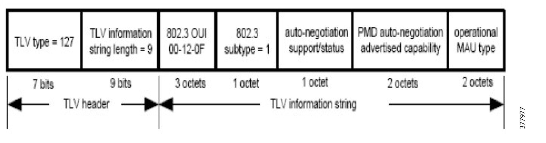
Digital Building Solution’s specific field settings include the following:
■![]() MAC/PHY Configuration/Status TLV (OUI = 00-12-0f, Subtype = 1)—MUST for LLDP-MED devices; contains AutoNeg details
MAC/PHY Configuration/Status TLV (OUI = 00-12-0f, Subtype = 1)—MUST for LLDP-MED devices; contains AutoNeg details
■![]() Power Via MDI TLV (OUI = 00-12-0f, Subtype = 2)—Lighting endpoints to use this for negotiating power
Power Via MDI TLV (OUI = 00-12-0f, Subtype = 2)—Lighting endpoints to use this for negotiating power
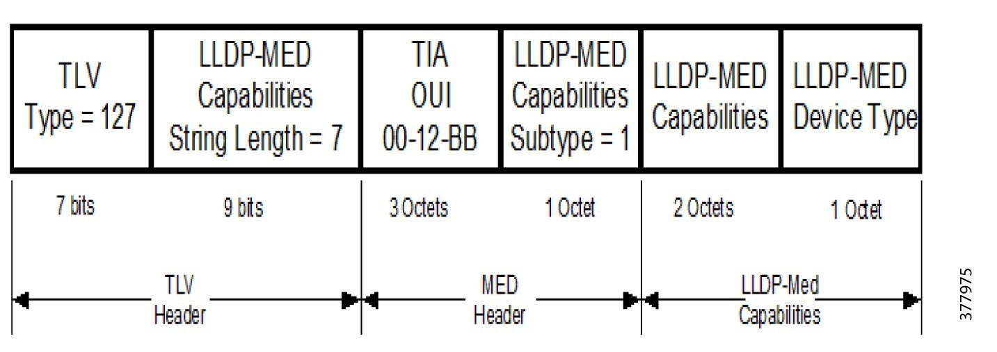
Figure 8 LLDP-MED TLV Extension (OUI = 00-12-BB)
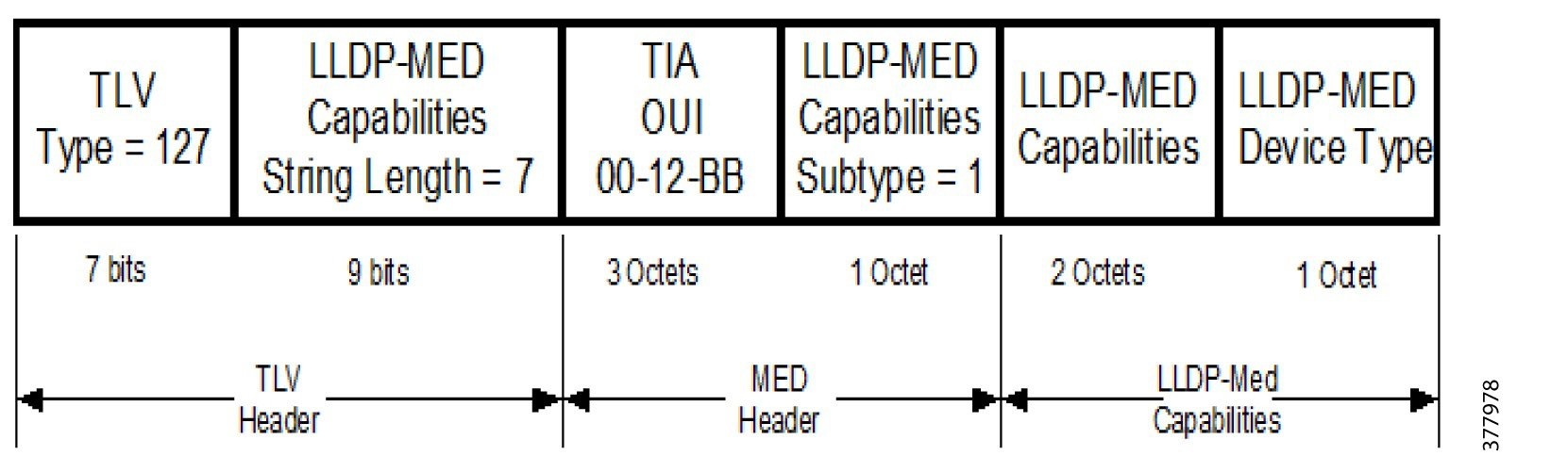
The bit positions for MED capabilities are shown in Table 7.
Digital Building Solution’s specific field settings include the following:
■![]() LLDP-MED Capabilities TLV (OUI = 00-12-BB, Subtype = 1):
LLDP-MED Capabilities TLV (OUI = 00-12-BB, Subtype = 1):
–![]() Set Device Type to 1 (Endpoint Class 1)
Set Device Type to 1 (Endpoint Class 1)
■![]() Network Policy TLV (OUI = 00-12-BB, Subtype = 2):
Network Policy TLV (OUI = 00-12-BB, Subtype = 2):
–![]() DSCP/CoS and VLAN (values could be 0, non-zero if required). This information is sent from Switch to Endpoint for the VLAN and QoS values that it should use.
DSCP/CoS and VLAN (values could be 0, non-zero if required). This information is sent from Switch to Endpoint for the VLAN and QoS values that it should use.
■![]() Extended Power-via-MDI TLV (OUI = 00-12-BB, Subtype = 4):
Extended Power-via-MDI TLV (OUI = 00-12-BB, Subtype = 4):
–![]() Power Source 'PSE'-Binary Value 01
Power Source 'PSE'-Binary Value 01
–![]() Power Priority 'Critical'-Binary Value 0001
Power Priority 'Critical'-Binary Value 0001
–![]() Power Value/Class as per Vendor device-Determined by the actual fixture
Power Value/Class as per Vendor device-Determined by the actual fixture
■![]() Inventory-specific TLVs (subtypes 5 through to 11 Standardized)-MUST for Cisco:
Inventory-specific TLVs (subtypes 5 through to 11 Standardized)-MUST for Cisco:
–![]() Hardware Revision (subtype 5): 1.0
Hardware Revision (subtype 5): 1.0
–![]() Firmware Revision (subtype 6): 1.0
Firmware Revision (subtype 6): 1.0
–![]() Software Revision (subtype 7): 1.0
Software Revision (subtype 7): 1.0
–![]() Serial Number (subtype 8): US-1234
Serial Number (subtype 8): US-1234
–![]() Manufacturer (subtype 9): Vendor ID
Manufacturer (subtype 9): Vendor ID
–![]() Model: LED-Dimmable (further model description)
Model: LED-Dimmable (further model description)
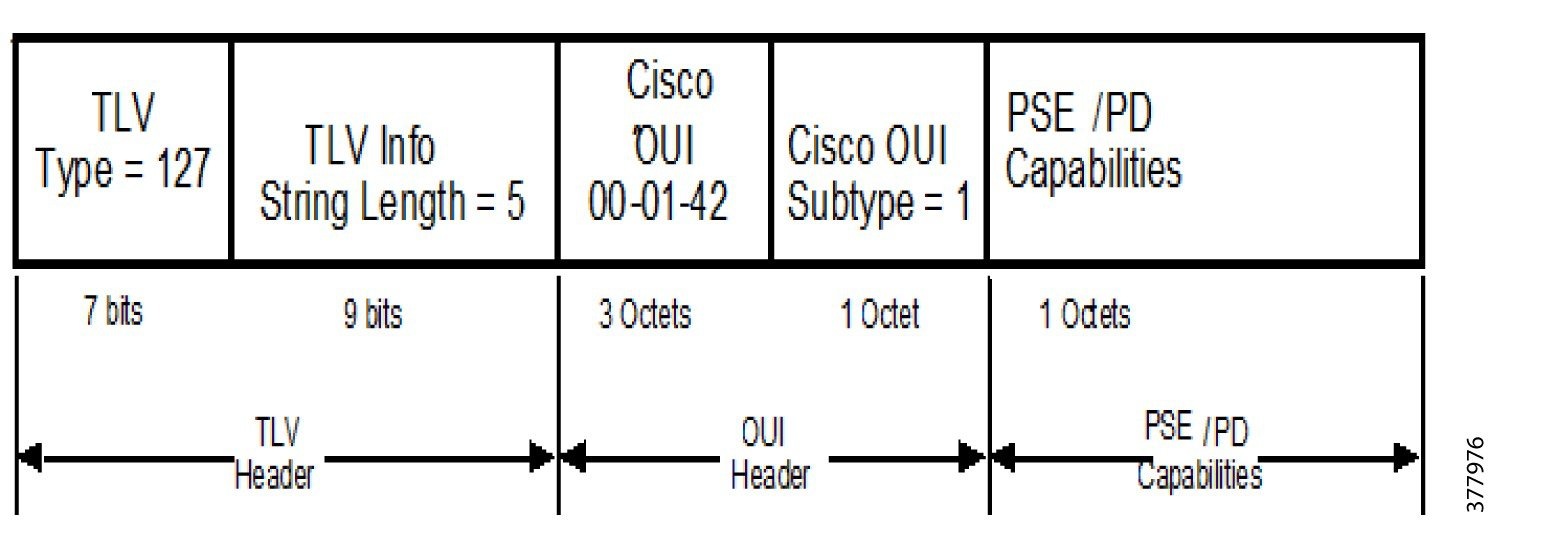
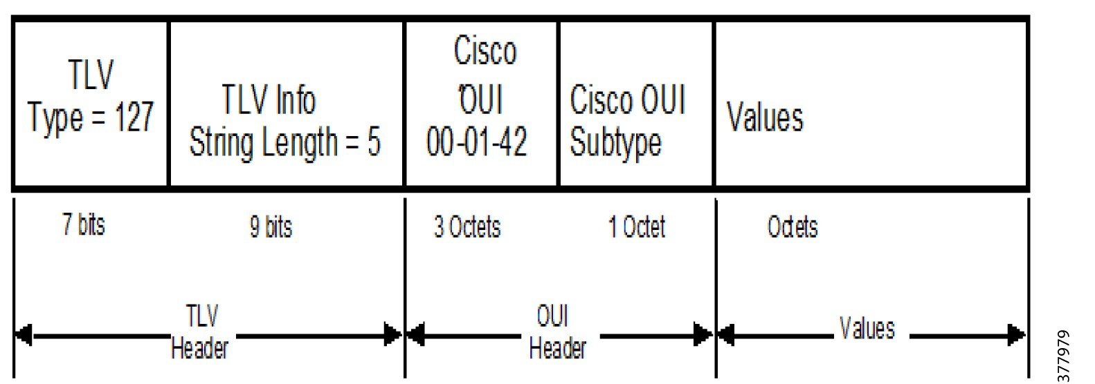
–![]() Cisco TLV Extension (OUI = 00-01-42)
Cisco TLV Extension (OUI = 00-01-42)
This is a new proposed TLV specific to lighting and sensor endpoints. For switches that do not support this TLV, this particular TLV would be ignored. Therefore, no impact is seen with respect to interoperability. See Figure 9.
Figure 9 LLDP Format of New TLV
Digital Building Solution’s specific field settings include the following:
This is similar to the system capabilities with the addition of the IOT device:
Broad classification of the applications supported; also indicates if this could be a read, read-write:
–![]() 0-Actuator; If set, Actuator Present
0-Actuator; If set, Actuator Present
–![]() 1-Sensor; If set, Sensor Present
1-Sensor; If set, Sensor Present
POE Switch Features for Digital Building Solution
Power Management Features
Cisco POE switches for the Digital Building Solution support the following features for power management.
Perpetual POE
The Perpetual POE feature supported on Cisco POE switch provides uninterrupted power to connected PD device even when the PSE switch is booting.
Fast POE
The Fast POE feature stores the information of power drawn from a particular port and re-allocates the power to the port once the power is restored.
■![]() For lighting endpoint devices implemented for 1-event classification, the lighting endpoint devices can restore power up to 15 watts after Fast POE process completion.
For lighting endpoint devices implemented for 1-event classification, the lighting endpoint devices can restore power up to 15 watts after Fast POE process completion.
■![]() For lighting endpoint devices implemented for 2-event classification, the lighting endpoint devices can restore power up to 30 watts after Fast POE process completion.
For lighting endpoint devices implemented for 2-event classification, the lighting endpoint devices can restore power up to 30 watts after Fast POE process completion.
■![]() For lighting endpoint devices that require LLDP negotiation, the lighting endpoint devices can partially power up lights with 1-event or 2-event classification and perform LLDP negotiation after the switch is fully booted up.
For lighting endpoint devices that require LLDP negotiation, the lighting endpoint devices can partially power up lights with 1-event or 2-event classification and perform LLDP negotiation after the switch is fully booted up.
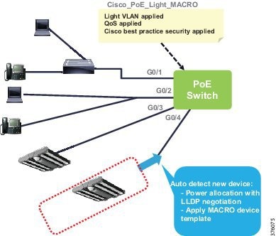
Auto Smartports Feature
Cisco Catalyst switches support Auto Smartports, which can be used to configure the switch ports automatically on detection of an endpoint device. The Auto Smartports feature is designed for easy management of the Cisco switches and to lower the operating costs.
With manual configuration, manual configuration changes are required after a device is disconnected. If the stale configuration was not removed accordingly, the next device connected to the port will not function properly.
The Auto Smartports feature automates the process by reverting the configuration to the previously applied configuration upon device disconnect. It removes any hard binding between the device and the interface to be ready for the new device.
Auto Smartports uses the device classification information gleaned from Cisco Discovery Protocol (CDP), LLDP, DHCP, and MAC OUI from the Device Classifier.
The LLDP Extension sent from the light device will provide the classification information required by Auto Smartports to trigger a pre-defined macro to be applied to the interface where the light device is attached.
The interface template for light device may include configurations associated with the type of light devices, VLAN assigned to the lighting subnet, and the QoS setting. See Figure 10.
Figure 10 Auto Smartports Operation
AutoConf and Interface Template:
■![]() AutoConf is a Catalyst switch feature that configures switch ports automatically on detection of an endpoint device and removes the config associate with a switch port when an endpoint device is removed.
AutoConf is a Catalyst switch feature that configures switch ports automatically on detection of an endpoint device and removes the config associate with a switch port when an endpoint device is removed.
■![]() Pre-defined Interface Template for light endpoint device can be automatically applied to the interface when the POE switch recognizes that the device is a light.
Pre-defined Interface Template for light endpoint device can be automatically applied to the interface when the POE switch recognizes that the device is a light.
■![]() LLDP protocol extension provides device information to determine if endpoint is a light device.
LLDP protocol extension provides device information to determine if endpoint is a light device.
Communication and Network Services
This section includes the following major topics:
■![]() Endpoint CoAP Server Expectations
Endpoint CoAP Server Expectations
The POE switch provides connectivity between the lighting devices enabling the lighting devices to communicate with lighting management software and other devices on the network. The POE switch also supports various networking functions such as security, routing, resource management, and monitoring. Since the POE switch is an aggregation point for lighting devices, it can serve as a central point to provide aggregated information to other parts of the network such as a resource directory.
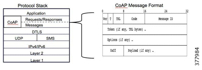
The CoAP is the communication protocol chosen for lighting devices to communicate with each other and to communicate with the lighting management software.
CoAP Support
Cisco Digital Building Solution adopts CoAP for device communications. The CoAP protocol is standardized by the Internet Engineering Task Force (IETF) in RFC 7252. It is a lightweight protocol suitable for the Internet of Things (IoT) environment. See Figure 11.
Figure 11 CoAP Protocol Stack and Message Format
The CoAP requests/responses defined by the standard are described in Table 8.
Notification upon resource info changes/cancellation of OBSERVE request |
Note: GET and PUT commands fulfill most of the Digital Building Solution use cases. Support of additional CoAP commands is implementation options.
The CoAP messages defined by the standards are described in Table 9. and CoAP responses are described in Table 10
The request was successfully received, understood, and accepted |
|
■![]() Is built on top of UDP, but has a built-in reliable message transport by sending messages with a CON flag set for messages that require acknowledgments. The sender will keep retransmitting until acknowledgment or timed out.
Is built on top of UDP, but has a built-in reliable message transport by sending messages with a CON flag set for messages that require acknowledgments. The sender will keep retransmitting until acknowledgment or timed out.
■![]() Allows CON messages and response message to be piggy-backed together so that the receiver can respond with ACK message in same time or can send the CON message followed by the response message later.
Allows CON messages and response message to be piggy-backed together so that the receiver can respond with ACK message in same time or can send the CON message followed by the response message later.
■![]() Adopts Datagram Transport Layer Security (DTLS) for end-to-end communication protection. DTLS is defined in RFC 6347 by IETF.
Adopts Datagram Transport Layer Security (DTLS) for end-to-end communication protection. DTLS is defined in RFC 6347 by IETF.
Discovery/Registry
Resource Director (RD) is a node that hosts descriptions of resources held on other servers, allowing lookups to be performed for those resources.
Resource Director Discovery
An endpoint that wants to make itself discoverable sends a registration request to the RD that it finds. Before an endpoint can register its resource to the RD, it must first know the RD's IP address and port and the path of the RD function.
■![]() Static Configuration—CoAP Resource Director's IP address is statically configured as the RDIP.
Static Configuration—CoAP Resource Director's IP address is statically configured as the RDIP.
■![]() Discovery via LLDP—It is possible to share the CoAP RD information in the LLDP information exchange.
Discovery via LLDP—It is possible to share the CoAP RD information in the LLDP information exchange.
■![]() Discovery via DHCP—The endpoint device queries the DHCP server, either one that is embedded with the CoAP Resource Director or a standalone DHCP server, to obtain the IP address of RD.
Discovery via DHCP—The endpoint device queries the DHCP server, either one that is embedded with the CoAP Resource Director or a standalone DHCP server, to obtain the IP address of RD.
■![]() Broadcast—The endpoint device sends a POST to /.well-known/core with no other payload using broadcast IP, the RD then sends a GET on /.well-known/core to discover all its resources.
Broadcast—The endpoint device sends a POST to /.well-known/core with no other payload using broadcast IP, the RD then sends a GET on /.well-known/core to discover all its resources.
Application Note: Cisco PoE switches support the Resource Director function using static configuration and broadcast mechanism for resource discovery.
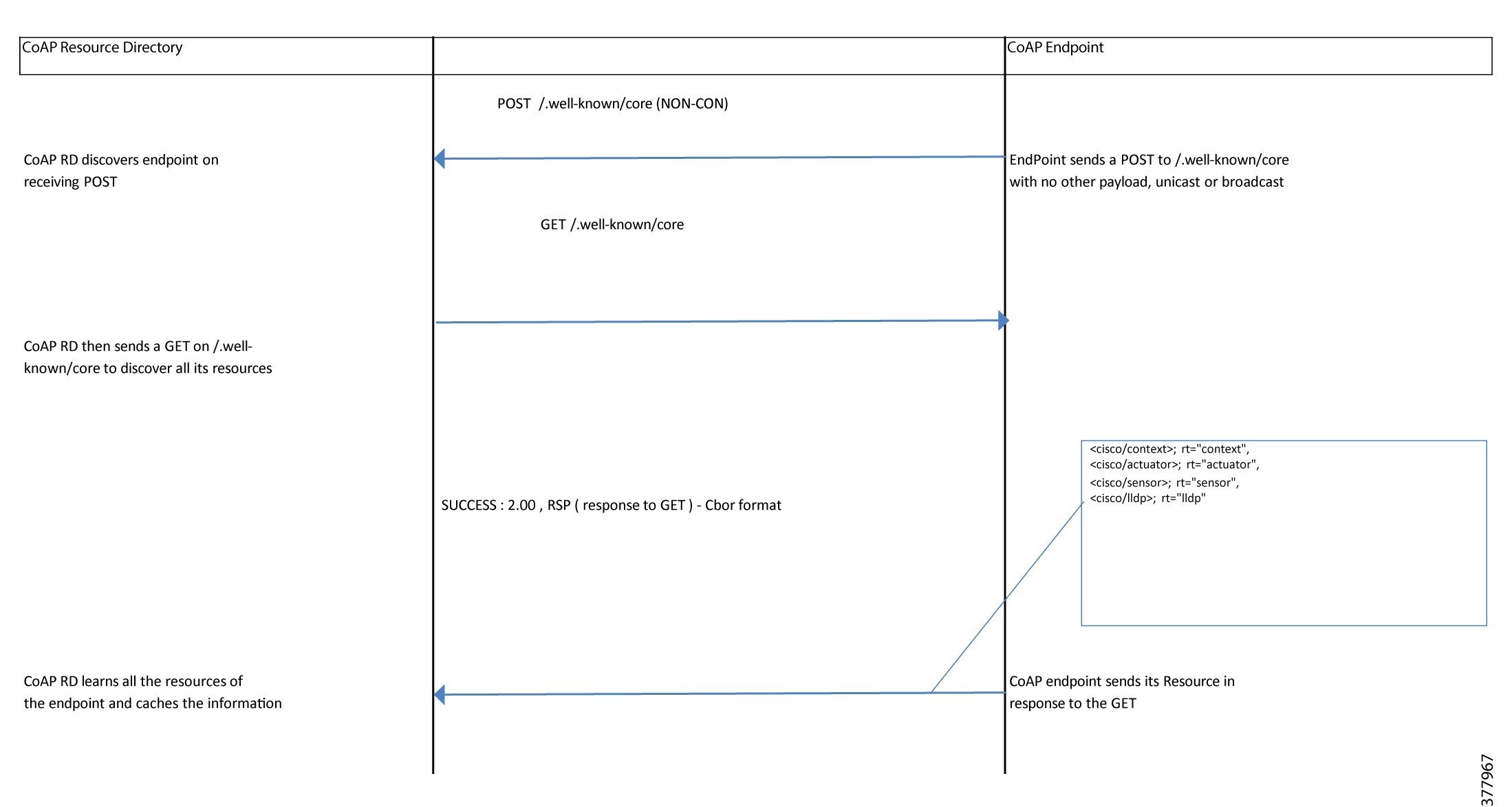
Resource Registration
An endpoint that wants to make itself discoverable sends a POST request to the /.well-known/core URI of any candidate directory server that it finds. The body of the POST request can be empty, in which case the directory server is encouraged by this POST request to send GET requests requesting endpoint device's resources. See Figure 12.
Figure 12 Resource Registration
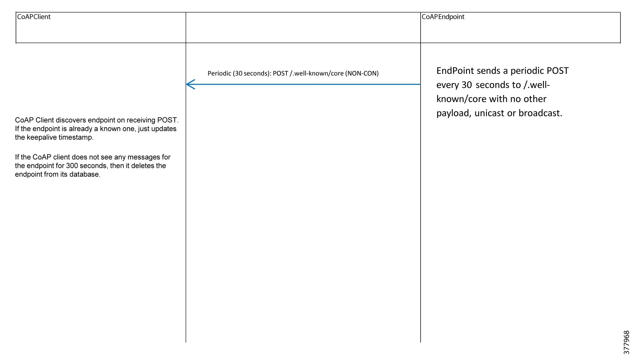
Resource Keepalive
Periodically the endpoint updates its registration information by sending a POST (or PUT) command to the /.well-known/core.
The RD removes the endpoint from the resource database if it has not received any messages from the endpoint within 300 seconds. If the endpoint is still alive, it should time out waiting for the RD to restart the discovery process again.
See Figure 13.
Resource Refresh
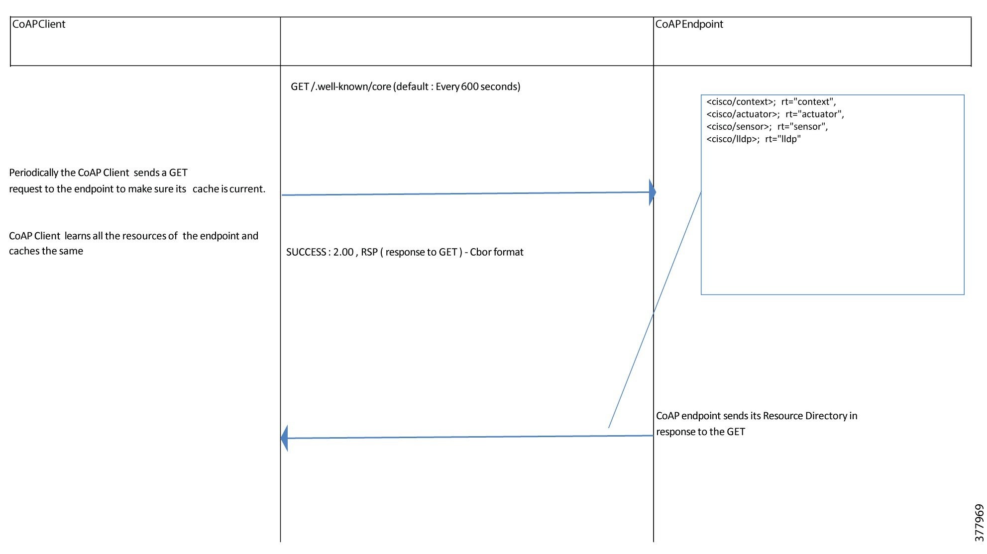
The RD periodically sends a GET request to the endpoints to make sure the cached information is up to date. See Figure 14.
Payload Format
For link registration, payloads are expected to be in application/link-type format. For application type information, the CoAP data model encoding and payload formats are left to a device and application to specify.
The default payload encoding for endpoint communications discussed in this document is in the application/cbor format.
Endpoint CoAP Server Expectations
A good way to achieve end-to-end interoperability among devices, services, and applications is to use a common set of abstractions and data model. The endpoint devices are required to implement the followings in order to be interoperable.
UUID
Each endpoint and component SHOULD contain a UUID. It is recommended the UUID complies with RFC4122 with the semantics of the entPhysicalUUID in RFC6933.
Accept
Since the default payload expected in this document is in application/cbor format, the endpoints MUST provide this format as the default. If a client expresses a preference via Accept (ex: application/json), the endpoint MAY return values in that format.
An endpoint that only returns payload in application/cbor MAY return 4.06 Not Acceptable for all other Accept requests.
Max-Age
A Max-Age SHOULD be provided and refreshed before transmissions.
Security
All endpoints are expected to provide a no security (NoSec) option. Additional security requirements are a function of the Digital Building Solution network architecture. A dedicated network that is air-gapped from the internet may need no additional security. On the opposite side, a mixed network of Digital Building IoT devices and computers, printers, and servers that is open to the outside internet will need the highest levels of security to remain secure.
The following security mechanisms are recommended:
1.![]() 802.1x Endpoint Authentication—Endpoint authentication prevents unauthorized endpoints from accessing the network:
802.1x Endpoint Authentication—Endpoint authentication prevents unauthorized endpoints from accessing the network:
a.![]() Using pre-shared keys (EAP-PSK)
Using pre-shared keys (EAP-PSK)
2.![]() Message Signing using HMAC Signatures—Message signing protects integrity of the contents of the message.
Message Signing using HMAC Signatures—Message signing protects integrity of the contents of the message.
3.![]() Secure Unicast Connections using DTLS—Provides tunneling between two endpoints for secure communication.
Secure Unicast Connections using DTLS—Provides tunneling between two endpoints for secure communication.
4.![]() Key Management using EST over CoAP—Provides secure management of keys and periodically key updates.
Key Management using EST over CoAP—Provides secure management of keys and periodically key updates.
Discovery
Endpoints MUST advertise their resources via the Resource Type Scheme in the CoRE Link Format.
UDP and Blockwise Transport
Endpoints are expected to use UDP with blockwise transport for CoAP requests and responses. At a minimum, endpoints should support a blockwise transmit of the discovery response when the endpoint is supporting many resources and the discovery response will not fit into a single UDP datagram.
Resource Naming
Resources SHOULD be expressed as a URI that contains a vendor prefix to distinguish vendor resource from common or standard resources.
Resource URI Encoding
Resource URIs along with optional parameters are expected to be expressed as string/text. Requests that need blockwise transport (for the request URI, not the response) should be avoided.
Filtering Expressions
The filtering parameters for endpoints are typically left to the individual implementations to set via convention. In order to allow for a simple querying scheme, attributes MAY be listed in a URI with an assumed filtering criterion.
■![]() Expression between different attributes is assumed to be a logical AND.
Expression between different attributes is assumed to be a logical AND.
■![]() Expressions among a specific attribute is assumed to be a logical OR.
Expressions among a specific attribute is assumed to be a logical OR.
Basic Resources and Information Models
Endpoints SHOULD implement resource(s) that provide the features designed by their manufacturers. It has been observed that the CoAP ecosystem is converging on a concept of Sensors and Actuators to categorize endpoints.
■![]() Sensors abstract measurements an endpoint could provide. Sensors are read-only, supporting only GETs but not PUTs.
Sensors abstract measurements an endpoint could provide. Sensors are read-only, supporting only GETs but not PUTs.
■![]() Actuators abstract the configuration of actions an endpoint could provide (for example, emitting light or positioning an HVAC damper). Actuators support both PUTs and GETs.
Actuators abstract the configuration of actions an endpoint could provide (for example, emitting light or positioning an HVAC damper). Actuators support both PUTs and GETs.
The following resources SHOULD be implemented by endpoints and are based on the Sensor Markup Language (SensorML) with the extensions discussed below. Examples of resources are as below. The root name here is cisco that can be replaced by vendor's name or product name. The resource names here are sensor and actuator. They are names of resources under the resource tree and can be replaced by any other names. Each endpoint must have at least one actuator or sensor.
A POST operation with no return code should be reserved for operations that add values to a resource (observers, for example). For the basic resource that is defined here, a POST without a 2.01 return would not apply since no information with additive attributes is defined.
Endpoints SHOULD implement the following sub-resource in order to provide basic information across endpoints and to provide interoperability.
These sub-resources can be placed under root or under sensor or actuator, as examples shown below.
Table 11 shows sub-resource placements.
The resources shown are expressed as JSON objects, but would be encoded as application/cbor. The attribute names of a JSON object expressed in CBOR would be encoded as opposed to hashed.
Information Models
Endpoints are expected to track information and present that information via resources. This section will describe the information model in a generic way that does not dictate storage or implementation for the endpoint; it just describes what the endpoint should track.
The model describes the minimal set of information needed. The model describes information pertaining to the identity, inventory, context, network, location, and measurements for the endpoint device. Measurements are modeled as sensor (readable only) and actuator (readable and writable) information.
For the modeling, it is assumed that:
■![]() An endpoint implements a CoAP server and may implement a CoAP client.
An endpoint implements a CoAP server and may implement a CoAP client.
■![]() The endpoint will contain context, identity, inventory, location, and network information.
The endpoint will contain context, identity, inventory, location, and network information.
■![]() The endpoint may contain multiple sensors/actuators that are components of the endpoint. Each endpoint MUST contain at least one sensor or actuator.
The endpoint may contain multiple sensors/actuators that are components of the endpoint. Each endpoint MUST contain at least one sensor or actuator.
■![]() The endpoint and each of its components will contain a UUID.
The endpoint and each of its components will contain a UUID.
UML Class Representations
Resources are described in a variant of the UML Class construct: CLASS name {member…}.
JSON and CBOR
■![]() JSON (JavaScript Object Notation) is defined in RFC 7159. It provides a low overhead alternative to XML.
JSON (JavaScript Object Notation) is defined in RFC 7159. It provides a low overhead alternative to XML.
■![]() CBOR (Concise Binary Object Representation) is defined in RFC 7049 to encode in binary to allow faster processing.
CBOR (Concise Binary Object Representation) is defined in RFC 7049 to encode in binary to allow faster processing.
JSON is easily translated to and from CBOR; therefore, resources are defined in JSON but encoded in the equivalent CBOR format. JSON is a minimal and readable format for structuring data. It is used primarily to transmit data between a server and application, as an alternative to XML. A JSON object has two primary parts:
■![]() Key—A key is a string enclosed in quotation marks.
Key—A key is a string enclosed in quotation marks.
■![]() Value—A value can be a string, number, boolean expression, array, or object.
Value—A value can be a string, number, boolean expression, array, or object.
Together they make a key/value pair. A key value pair follows a specific syntax, with the key followed by a colon followed by the value. Key/value pair is separated by a comma.
CBOR is to encode the readable JSON format into binary to reduce bulkiness. "cbor.me" is a website resource to translate JSON to CBOR representation.
Examples of JSON objects and their CBOR equivalents can be found in Appendix C: Resource Examples.
Sensor Markup Language
Sensors are described using Sensor Markup Language (SenML). SenML also forms the basis for actuators and all other resources as well. SenML is defined in Media Types for Sensor Markup Language (SenML). This document is based on the IETF version "draft-jennings-core-senml-01."
The basic format of a SenML object is a collection of time and version information, followed by an array of measurements as shown below:
The base name (bn) is an optional field, since each resource is identified by its URI path (example: /root_dir/sensors/LightSensor/). Base time and base units are optional, they can be reported in each measurement result if necessary.
Earlier in this document, the followed is stated:
UUID: Each endpoint and component should contain a UUID. It is recommended the UUID complies with RFC4122 with the semantics of the entPhysicalUUID in RFC6933.
An " OtherN " slot is taken to define a base UUID (buuid), which can be concatenated with a measurement, as defined below:
The information based on SenML will be formatted as JSON/CBOR representation. The XML/XMI formats described in the SenML draft will not be use.
Sensor measurements are defined as a JSON object containing name:value pairs, separated by commas. The allowable names, including extensions to the draft RFC, are shown below:
A measurement can be expressed using an integer, float, string, or boolean, but only one expression is permitted. For example, room temperature can be reported as a number or as a string, but not both in the same measurement.
Measurement Class Values
The following table of values can be easily expanded by adding new classes when new sensors need to be measured.
Measurement Class Values and Related Units
Example Sensor Resources
An example of a sensor that measures the light color in a room is shown below:
Multiple measurement results can be reported in the same entry array, "e." An example of a board power drawn (pd) sensor object, reporting that the endpoint is drawing 3500 mWatts (3.5 Watts), is shown below:
Resource View
In addition to sensor resources, non-sensor resources such as actuators exist.
{ "buuid":"uuid_value_string", "e":[entry array of objects] }
can still serve as the basis to describe non-sensor resources.
As a simplification, the buuid field can be eliminated and report the UUID for the resource as part of the entry array. The result is Resource UUID = entry UUID for non-sensor resources.
Sensors are intrinsically read only, but non-sensor resources, including actuators, are a mixture of name:value pairs that are read only (ro) or (r/w) with respect to CoAP messaging. Read only name:value pairs in the model below are not necessarily constant. For example, the swrv shown below in Inventory is "ro,” meaning that swrv cannot be changed by CoAP PUT command, but it is changed when the endpoint's software is updated. On the other hand, the model number description in Inventory is truly read only. It should never be changed after leaving the manufacturer.
The following examples of resource view are illustrated based on sub-resources are common to sensor/actuator (flat resource representation), as discussed in Table 11. It is also applicable to scenarios where sub-resources are unique to sensor/actuator (tree resource presentation), as described in Table 11.
Identity Resource
Based on RFC7326 and RFC7461. All values are ReadOnly.
Context Resource
Based on RFC7326 and RFC7461. All values are ReadWrite.
Application Note: An example of keywords implementation is to use keywords such as Critical_Pathlight in the key word array, together with broadcast CoAP messages containing a key word query, to control groups of lights.
Location Resource
No widely accepted way exists for describing endpoint Location. A string provided by the endpoint device is used to support all possible format. The value is ReadOnly.
Sensors and actuators can have a different location than the endpoint's hardware, requiring a dedicated location resource such as:
Inventory Resource
Endpoint Inventory provides a way of knowing hardware/firmware/software revision numbers as well as manufacturer name and model description.
Gateway endpoints translate CoAP into the native format of the devices it hosts. A gateway endpoint may host actuators/sensors from other manufacturers, thus requiring an inventory resource for some of the devices it hosts.
Devices may lack firmware or software as well, leading to a resource without all the key:value pairs.
Network Resource
The network resource provides networking information of the endpoint resides in the network.
Application Note: IPV6 address can be a single string or an array of strings. Details of the Building Management address and name can be r/w or ro, depending on how security is handled. Typically these will be ro in CoAP and rw when in a Secure CoAP DTLS socket between the endpoint and Building Management System.
Actuator Resource
The Actuator resource includes the name:value pairs needed to control a LED light. The set of name:value pairs shown below is a superset. Some, such as "pp," "ar," or "oK," are optional.
■![]() "PP" and "pi" value can only be changed (using PUT) one at a time
"PP" and "pi" value can only be changed (using PUT) one at a time
■![]() "ar" and "at" value can only be changed (using PUT) one at a time
"ar" and "at" value can only be changed (using PUT) one at a time
■![]() "ok" and "lc" value can only be changed (using PUT) one at a time
"ok" and "lc" value can only be changed (using PUT) one at a time
See additional implementation choices in Appendix E: Implementation Options.
The lighting control software can set the or flag to 1, which will:
1.![]() Set light levels to 100% (implementation choice).
Set light levels to 100% (implementation choice).
2.![]() Prevent the light from executing changes in light power from any other wall controller.
Prevent the light from executing changes in light power from any other wall controller.
How the light controller recognizes the BMS or equivalent is to be determined.
Optional Resources: DFD and DFU
DFD and DFU resources are used for downloading and updating the new boot image.
uuid: Universally Unique Identifier, ro
tsrv: TFTP IP Address as a string, r/w
tnam: TFTP file name for download as a string, r/w
tbeg: Time to begin DFD, in seconds since 1/1/1970, as an integer, r/w
tbsz: TFTP block size in bytes as an integer, r/w
uuid: Universally Unique Identifier, ro
updt: Time for firmware update, in seconds since 1/1/1970, as an integer, r/w
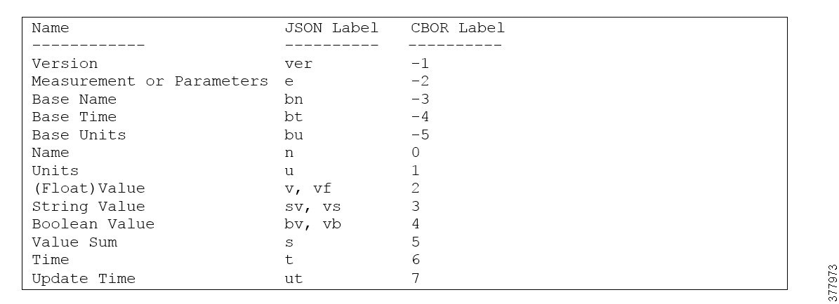
CBOR Label (Sensor/Actuator)
The labels specified in draft-jennings-core-senml-01 will be used, as shown in Figure 15.
Figure 15 CBOR Label (Sensor/Actuator)
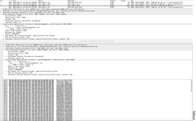
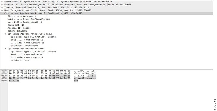
Appendix A: LLDP Packet
The following is an example of a LLDP packet trace sent by a lighting endpoint.
Appendix B: CoAP Messaging Examples
Examples of CoAP messages are shown in Figure 16 and Figure 17. The use case for the device registration is illustrated below as discussed in the resource registration section.
Here is a CoAP GET example for retrieving resources under /well-know/core.
Appendix C: Resource Examples
This appendix shows resource examples for JSON and CBOR and Reference Endpoint.
JSON and CBOR
CBOR is a binary encoding of JSON. This document shows all information using JSON notation because it is readable and is in text format. The equivalence of JSON versus CBOR is specified in RFC7049. A useful site for testing and checking CBOR information can be found at the following URL:
The following shows an example of the /cisco/context attributes encoded in both JSON and CBOR (without labels) to illustrate some encoding.
JSON
CBOR Label (Sensor/Actuator)
The labels specified in draft-jennings-core-senml-01 will be used. See Figure 18.
Figure 18 CBOR Label (Sensor/Actuator)
Reference Endpoint
For illustration, Figure 19 shows a reference endpoint: a lighting fixture with two controllable lights and two sensors for motion and temperature.
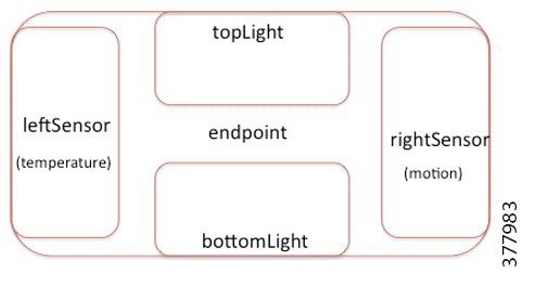
The payload will be described using JSON, but would minimally be presented in CBOR in transmission using CBOR Labels where defined.
Appendix D: Software, Hardware, and Useful Tools
This appendix provides a brief summary of software and hardware of a simple setup in order to get started. Figure 20 is an example of a simple topology for integration.
Figure 20 Example CoAP Topology
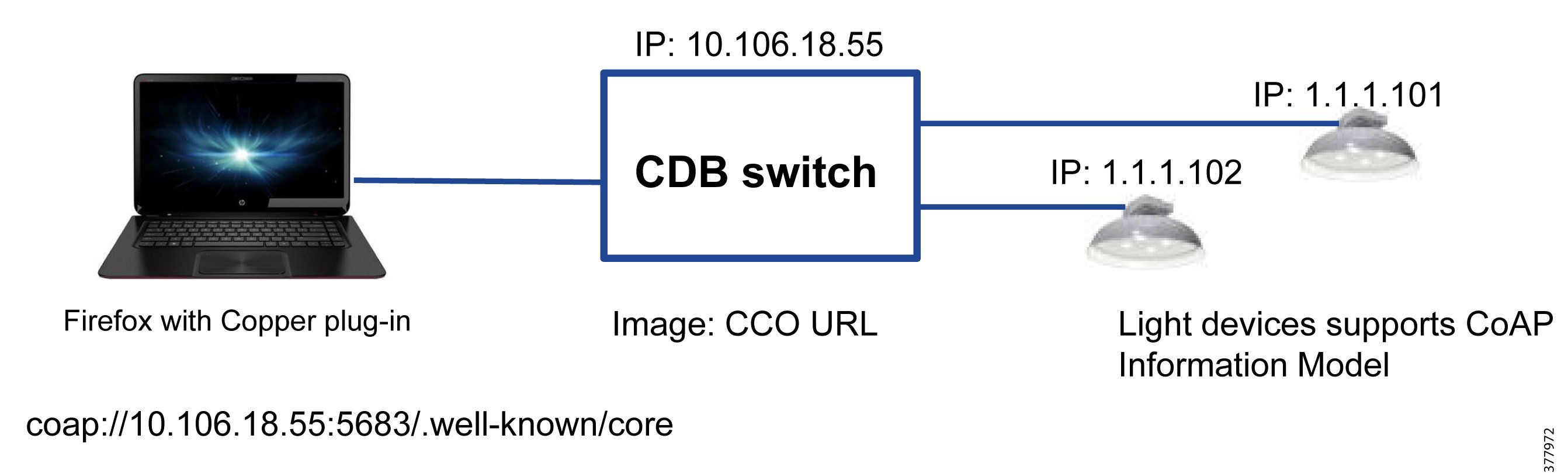
Table 12 is a list of software and hardware used as a simple setup for the integration efforts.
Hardware: CDB-8U for UPOE/CDB-8P for POE+ support |
||
Download Copper plug-in for Firefox or purpose-built lighting control software |
* or a POE switch listed in Table 3 that meet power requirement needs.
POE Switch Configuration
A CDB-8U POE switch provides up to 480W to power up to 8 devices connected to the POE switch. Each port supports up to 60W POE power. Similarly, a CDB-8P POE switch supports up to 8 POE+ devices with total of 240W available power.
An example of simple development and test topology is depicted in Figure 20. The CDB switch is purposely built for the Digital Building environment that requires very minimum setup and configuration. On a CDB switch, the following configurations is enabled by default:
1.![]() 2-event classification and LLDP
2-event classification and LLDP
2.![]() POE features - Fast POE and Perpetual POE
POE features - Fast POE and Perpetual POE
The CDB switches have the following day 0 configuration on the POE ports:
Additional configuration recommendation to be enabled on the CDB switches:
–![]() Define DHCP Pool name and address range:
Define DHCP Pool name and address range:
2.![]() Configure VLAN, which is used to communicate to the luminaires:
Configure VLAN, which is used to communicate to the luminaires:
–![]() Configure VLAN to the interface(s) to which lighting endpoint devices are connected:
Configure VLAN to the interface(s) to which lighting endpoint devices are connected:
–![]() Configure the VLAN interface:
Configure the VLAN interface:
3.![]() Enable truck on the uplink interfaces.
Enable truck on the uplink interfaces.
–![]() The two uplink interfaces to aggregate traffic are:
The two uplink interfaces to aggregate traffic are:
End-to-end Solution
The CoAP-based lighting endpoint devices should lit up once plug into the CDB ports. Use either Copper plug-in or purpose-built lighting control software to further control the lights and collect information from the sensors.
Firefox Copper plug-in allows users to browse the URI resources and send CoAP commands to the resources. A lighting control software can provide more in-depth lighting control with grouping or light scene, etc.
Appendix E: Implementation Options
Managing Light Resources
Managing Light Resources via GET and PUT
Light intensity is commanded by a PUT specifying either "pp" or "pi" but not both. A PUT providing both "pp" and "pi" should implement the "pi" and ignore the "pp."
Light color is commanded by a PUT specifying either "cl" or "oK" but not both. A PUT providing both "cl" and "oK" should implement the "cl" and ignore the "oK."
A GET with a "oK" value of zero and an empty string for "cl" implies that the light's color is unknown. Endpoints can support color by one or both methods. It is recommended that PUTs to an unsupported color definition produce a "Method Not Allowed" response. Alternately, the PUT can be simply ignored.
The speed of an adjustment in light illumination is commanded by either "ar" or "at" but not both. When a PUT provides both “at” and “ar,” the "at" value should be used and the "ar" ignored. To only change the light's color, use "at". A PUT that only changes color, leaving illumination alone, and that specifies "ar," should simply implement the color change immediately.
Percent Power vs. Percent Intensity
Human perception of light intensity does not vary linearly with the power actually fed to an LED light. Typically, a lookup table (LUT) or function that converts percent intensity into percent power exists. This is shown by the plot in Figure 21.
The percent power applied to the light is equivalent, in most cases to the PWM duty cycle applied to the LED driver circuit. The plot in Figure 22 shows that a linear relationship exists between the PWM duty cycle and the total power drawn by the lighting controller board. Thus, we can use PWM Duty cycle as equivalent to Percent Power.
Figure 21 Percent Intensity versus PWM Duty Cycle LUT
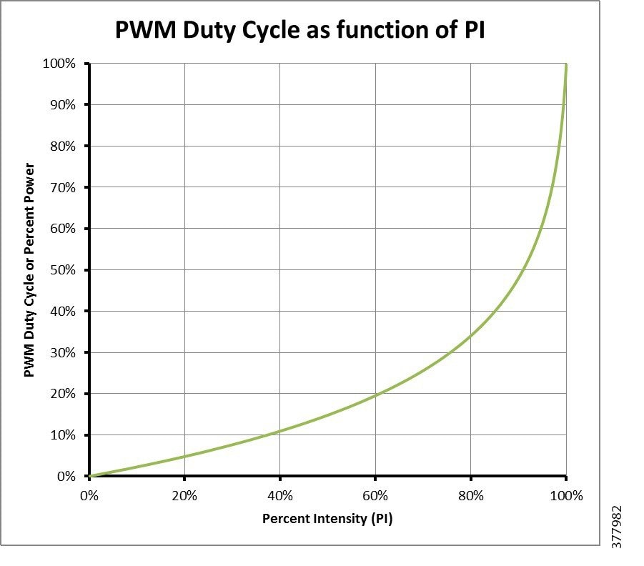
Figure 22 Percent Power vs. Board Power Drawn
Given a % Intensity (pi) the equivalent PWM duty cycle is determined using a LUT. Given a % Power (pp) the PWM duty cycle is known simply by PWM Duty Cycle = % Power. Lighting controller endpoints must support pi. If both are supported then the endpoint should only accept one, but not both, in any single PUT. If the endpoint receives PUT with both it should ignore the pp and implement the pi. On an endpoint that supports both pi and pp, when PUT provides either pi or pp the LUT MUST be used to calculate the other value. When both pi and pp are provided in PUT, the pp value is ignored and recalculated using pi in the LUT.
Why do you need to set one using the LUT when providing the other? Simple. Suppose this is not done. A dimming wall switch could set pi = 0% to turn the light off and then a little later the Building Management System (BMS) could set the same light to pp = 100%. The light would then report in a GET of the actuator that pi = 0% and pp = 100%. Which would be that actual light level? Following this recommended policy, when the BMS set pp = 100% the endpoint would then use the PI<->PP LUT to set pi to 100%. Then a subsequent GET of the actuator would show pi = 100% and pp = 100%.
Adjustment Rate versus Adjustment Time
A lighting controller should provide support for gradually changing light and/or color. If this feature is supported it is recommended that adjustment time (at) be implemented before adjustment rate (ar) since at applies to both light intensity and color, while ar only applies to lighting intensity. Any new lighting and/or color value change should be instantaneous when:
at = 0 (ar not implemented) or when both at = 0 and ar = 0 (both are implemented).
Specifying an ar when only changing the light's color should simply cause the light's color to change instantaneously, since light color is not specified as a percentage. (On the other hand, if a new light level is provided along with a new color and an adjustment rate (ar), the equivalent adjustment time (at) can be calculated based on the difference between the old light level versus the new light level. Then this adjustment time can be used to change the light's color.)
Light Color as Degrees Kelvin versus RGBW
Light color can be specified by degrees Kelvin (oK), using a black body radiation model, or using RGBW levels (cl) (8 bits per color, with 0 = Off and 255 = Fully On). Endpoints should support RGBW and may support degrees Kelvin. If both are provided in a PUT, the endpoint should ignore oK and implement cl.
Managing Groups of Lights
Secure communication via DTLS unicast pipes works for connections between the BMS and individual endpoints. But there is no technology today to provide secure DTLS multicast between the BMS and groups of lights.
DTLS Multicast by Proxy
An alternative is to use a DTLS Multicast by Proxy: In this approach, a Proxy Server uses secure DTLS unicast pipes between it and each endpoint in the lighting group. The proxy server receives a lighting command from the BMS and then copies and sends it down each unicast pipe to control each endpoint one at a time.
Figure 23 DTLS Multicast by Proxy
Large groups of lights may experience unacceptable delays because of the number of unicast connections. Typically this would be seen in a large hotel ballroom or convention center with hundreds of lights to be controlled.
HMAC Digital Signatures with Broadcast or Multicast
An alternative to DTLS Multicast by Proxy is to use HMAC digital signatures on each CoAP message, securely signing each multicast or broadcast packet that is sent by the BMS with the message payload unencrypted. For this to work, the BMS must first install a shared secret key on each endpoint in the lighting group, which can be used by each endpoint to validate that each broadcast or multicast message received did originate from the BMS. Also, a sequence number will be necessary in the message to prevent replay attacks.
Lighting groups can be organized by keyword queries with broadcast packets or with multicast groups.
Clearly the trade-off is the ease of use that comes with broadcast or multicast traffic at the cost of sending lighting commands in the clear. (They can be seen but not spoofed.)
Appendix F: References
The following is the list of documents relevant to the Cisco Digital Building Solution.
Published Documents
■![]() Cisco UPOE White Paper (Cisco Universal Power Over Ethernet: Unleash the Power of your Network):
Cisco UPOE White Paper (Cisco Universal Power Over Ethernet: Unleash the Power of your Network):
–![]() http://www.cisco.com/c/en/us/products/collateral/switches/catal yst-4500-series-switches/white_paper_c11-670993.pdf
http://www.cisco.com/c/en/us/products/collateral/switches/catal yst-4500-series-switches/white_paper_c11-670993.pdf
■![]() Software Configuration Guide, Cisco IOS Release 15.2(5)EX (Catalyst Digital Building Series Switches):
Software Configuration Guide, Cisco IOS Release 15.2(5)EX (Catalyst Digital Building Series Switches):
–![]() http://www.cisco.com/c/en/us/td/docs/switches/lan/catalyst_digital_building_series_switches/software/15-2_5_ex/configuration_guide/b_1525ex_consolidated_cdb_cg.pdf
http://www.cisco.com/c/en/us/td/docs/switches/lan/catalyst_digital_building_series_switches/software/15-2_5_ex/configuration_guide/b_1525ex_consolidated_cdb_cg.pdf
■![]() Cisco Catalyst Digital Building Series Switches Data Sheet
Cisco Catalyst Digital Building Series Switches Data Sheet
–![]() http://www.cisco.com/c/en/us/solutions/collateral/workforce-experience/digital-building/datasheet-c78-738206.html
http://www.cisco.com/c/en/us/solutions/collateral/workforce-experience/digital-building/datasheet-c78-738206.html
■![]() Catalyst Digital Building Series Switch Hardware Installation Guide
Catalyst Digital Building Series Switch Hardware Installation Guide
–![]() http://www.cisco.com/c/en/us/td/docs/switches/lan/catalyst_digital_building_series_switches/hardware/install/b-cdb-hig.pdf
http://www.cisco.com/c/en/us/td/docs/switches/lan/catalyst_digital_building_series_switches/hardware/install/b-cdb-hig.pdf
■![]() Software Configuration Guide, Cisco IOS Release 15.2(5)EX (Catalyst Digital Building Series Switches)
Software Configuration Guide, Cisco IOS Release 15.2(5)EX (Catalyst Digital Building Series Switches)
–![]() http://www.cisco.com/c/en/us/td/docs/switches/lan/catalyst_digital_building_series_switches/software/15-2_5_ex/configuration_guide/b_1525ex_consolidated_cdb_cg.html
http://www.cisco.com/c/en/us/td/docs/switches/lan/catalyst_digital_building_series_switches/software/15-2_5_ex/configuration_guide/b_1525ex_consolidated_cdb_cg.html
■![]() Cisco SNMP reference link to LLDP MIB:
Cisco SNMP reference link to LLDP MIB:
–![]() http://snmp.cloudapps.cisco.com/Support/SNMP/do/BrowseMI B.do?local=en&step=2&mibName=LLDP-MIB-V1SMI
http://snmp.cloudapps.cisco.com/Support/SNMP/do/BrowseMI B.do?local=en&step=2&mibName=LLDP-MIB-V1SMI
■![]() Ludovici, Calversa, A Proxy Design to Leverage the Interconnection of CoAP Wireless Sensor Networks with Web Applications, 2015, ISSN 1424-8220:
Ludovici, Calversa, A Proxy Design to Leverage the Interconnection of CoAP Wireless Sensor Networks with Web Applications, 2015, ISSN 1424-8220:
–![]() http://www.mdpi.com/1424-8220/15/1/1217
http://www.mdpi.com/1424-8220/15/1/1217
■![]() B Claise, J Parello, EMAN: Energy-Management Activities at the IETF, Internet Computing IEEE Volume 17 Issue 3, May 2013:
B Claise, J Parello, EMAN: Energy-Management Activities at the IETF, Internet Computing IEEE Volume 17 Issue 3, May 2013:
–![]() https://tools.ietf.org/html/draft-ietf-eman-energy-aware-mib-17
https://tools.ietf.org/html/draft-ietf-eman-energy-aware-mib-17
■![]() J Parello, R Saville, S Kramling, Cisco EnergyWise Design Guide, September 2010:
J Parello, R Saville, S Kramling, Cisco EnergyWise Design Guide, September 2010:
–![]() http://www.cisco.com/en/US/docs/solutions/Enterprise/Borderl ess_Networks/Energy_Management/energywisedg.html
http://www.cisco.com/en/US/docs/solutions/Enterprise/Borderl ess_Networks/Energy_Management/energywisedg.html
■![]() LLDP Overview (2003 presentation):
LLDP Overview (2003 presentation):
–![]() www.ieee802.org/1/files/public/docs2002/LLDP%20Overview. pdf
www.ieee802.org/1/files/public/docs2002/LLDP%20Overview. pdf
IETF
■![]() IETF ACE Working Group Charter:
IETF ACE Working Group Charter:
–![]() https://datatracker.ietf.org/wg/ace/charter/
https://datatracker.ietf.org/wg/ace/charter/
Draft Documents
■![]() LLDP Media Endpoint Discovery Project, LLDP-MED:
LLDP Media Endpoint Discovery Project, LLDP-MED:
–![]() http://www.cs.columbia.edu/sip/draft/civic/notes/LLDP-MED% 20Draft%2007-R1.doc
http://www.cs.columbia.edu/sip/draft/civic/notes/LLDP-MED% 20Draft%2007-R1.doc
■![]() draft-bormann-jose-cose. Constrained Object Signing and Encryption (COSE):
draft-bormann-jose-cose. Constrained Object Signing and Encryption (COSE):
–![]() https://tools.ietf.org/html/draft-bormann-jose-cose-00
https://tools.ietf.org/html/draft-bormann-jose-cose-00
■![]() draft-ietf-ace-usecases, Ace Use Cases:
draft-ietf-ace-usecases, Ace Use Cases:
–![]() https://tools.ietf.org/html/draft-seitz-ace-usecases-00
https://tools.ietf.org/html/draft-seitz-ace-usecases-00
■![]() draft-ietf-core-groupcomm-25, Group Communication for CoAP:
draft-ietf-core-groupcomm-25, Group Communication for CoAP:
–![]() https://tools.ietf.org/html/draft-ietf-core-groupcomm-25
https://tools.ietf.org/html/draft-ietf-core-groupcomm-25
■![]() draft-ietf-core-resource-directory-05
draft-ietf-core-resource-directory-05
–![]() https://tools.ietf.org/html/draft-shelby-core-resource-directory- 05
https://tools.ietf.org/html/draft-shelby-core-resource-directory- 05
■![]() draft-ietf-jose-json-web-signature
draft-ietf-jose-json-web-signature
–![]() https://tools.ietf.org/html/draft-jones-json-web-signature-00
https://tools.ietf.org/html/draft-jones-json-web-signature-00
■![]() draft-jennings-core-senml-01, JSON Web Signature (JWS)
draft-jennings-core-senml-01, JSON Web Signature (JWS)
–![]() https://tools.ietf.org/html/draft-jennings-core-senml-00
https://tools.ietf.org/html/draft-jennings-core-senml-00
■![]() draft-selander-ace-object-security, Object Security for CoAP
draft-selander-ace-object-security, Object Security for CoAP
–![]() https://tools.ietf.org/html/draft-selander-ace-object-security-00
https://tools.ietf.org/html/draft-selander-ace-object-security-00
RFCs
–![]() https://tools.ietf.org/html/rfc6933
https://tools.ietf.org/html/rfc6933
■![]() RFC 6690 Constrained RESTful Environments (CoRE) Link Format:
RFC 6690 Constrained RESTful Environments (CoRE) Link Format:
–![]() https://tools.ietf.org/html/rfc6690
https://tools.ietf.org/html/rfc6690
■![]() RFC 7049 Concise Binary Object Representation (CBOR):
RFC 7049 Concise Binary Object Representation (CBOR):
–![]() https://tools.ietf.org/html/rfc7049
https://tools.ietf.org/html/rfc7049
■![]() RFC 7252 Shelby, Z.; Hartke, K.; Bormann, C. The Constrained Application Protocol (CoAP); IETF, October 2014:
RFC 7252 Shelby, Z.; Hartke, K.; Bormann, C. The Constrained Application Protocol (CoAP); IETF, October 2014:
–![]() https://tools.ietf.org/html/rfc7252
https://tools.ietf.org/html/rfc7252
■![]() RFC 7326 Information Model for Energy Management (context):
RFC 7326 Information Model for Energy Management (context):
–![]() https://tools.ietf.org/html/rfc7326
https://tools.ietf.org/html/rfc7326
■![]() RFC 7390 Group Communication for the Constrained Application Protocol (CoAP):
RFC 7390 Group Communication for the Constrained Application Protocol (CoAP):
–![]() https://tools.ietf.org/html/rfc7390
https://tools.ietf.org/html/rfc7390
 Feedback