Quick Integration Guide for Cisco IoT FND in Pre-Shared Key-Based Deployments
Available Languages
Bias-Free Language
The documentation set for this product strives to use bias-free language. For the purposes of this documentation set, bias-free is defined as language that does not imply discrimination based on age, disability, gender, racial identity, ethnic identity, sexual orientation, socioeconomic status, and intersectionality. Exceptions may be present in the documentation due to language that is hardcoded in the user interfaces of the product software, language used based on RFP documentation, or language that is used by a referenced third-party product. Learn more about how Cisco is using Inclusive Language.
- US/Canada 800-553-2447
- Worldwide Support Phone Numbers
- All Tools
 Feedback
 Feedback
Cisco IoT FND deployment using OVA on ESXi
Import Cisco IoT FND OVA file into an ESXi host
Additional Changes to Cisco IoT FND VM before Power On
Bring up of FND using Shell configurations
Network and system configurations
Static name resolution for TPS domain name
Configure PSK and IPAM in Cisco IoT FND Shell
Integrate TPS with Cisco IoT FND
Configure TPS network settings
Configure static name resolution
Update CGMS keystore and TPS proxy properties
Integrate HER with Cisco IoT FND
Add field routers to Cisco IoT FND
Configure Cisco IoT FND provisioning settings
Add tunnel provisioning templates
Create a tunnel group and add field routers
Add router tunnel addition template
Add HER tunnel addition template
Add HER tunnel deletion template
Create field router configuration group
Identify Maximum IPv4 MTU supported by network provider using sweep ping
Identify the Maximum TCP Maximum Segment Size (MSS) supported by Network Provider
The objective of this document is to provide quick integration steps to onboard Cisco IoT Field Network Director (FND) and to integrate it with other components like tunnel provisioning servers (TPS) and head-end routers (HER). It also covers steps required to configure and make use of the IP Address Management (IPAM) functionality (in-built DHCP Server) in Cisco IoT FND.
Note: This guide only applies to greenfield deployments.
The integration tunnel between a field router and the head-end router is secured with IPSec tunnels using pre-shared keys (PSK). This document also covers the templates that are essential for PnP bootstrapping,and Zero Touch Deployment (ZTD) of field routers.
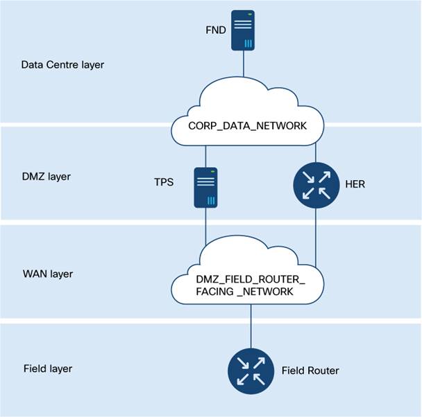
Table 1. Minimum version for the integration
| Component |
Description |
Minimum version required |
Version used in the documented examples |
| ESXi |
Hypervisor |
6.5 |
7.0U3 |
| FND |
Field Network Director / NMS |
5.0 |
5.0 |
| TPS |
Tunnel Proxy Server |
5.0 |
5.0 |
| Cisco Catalyst 8000 platform |
Head-end router |
17.9.5 |
17.12.4b |
| IR1101 |
Field router |
17.9.5b |
17.15.3 |
For the most recent version compatibility information, see Release Notes for Cisco IoT Field Network Director, Release 5.0.x.
Print out the Essential configuration items table (Table 11), and fill out the values for the configuration items for reference as you carry out the tasks in this guide.
Cisco IoT FND deployment using OVA on ESXi
This section provides an overview of deploying Cisco IoT FND using an Open Virtual Appliance (OVA) file on VMware ESXi. It covers the prerequisites, installation steps, and configurations necessary to set up the Cisco IoT FND environment effectively.
Table 2. Essential configuration items for Cisco IoT FND OVA deployment on ESXi
| Configuration Item |
Description |
| ESXI_HOST_URL |
IP Address of the ESXi host (version 6.5 and above) where the Cisco IoT FND VM will be deployed. |
| ESXI_HOST_USERNAME |
Username to access the ESXi host. |
| ESXI_HOST_PASSWORD |
Password to access the ESXi host. |
| FND_OVA_IMAGE |
Cisco IoT FND OVA image. |
| ADMIN_NETWORK_PORTGROUP |
ESXi port group that will be used for Admin Network SSH and GUI access. |
| CORP_DATA_NETWORK_PORTGROUP |
ESXi port group that will be used for Corporate Data Network for the communication of Cisco IoT FND with HER, TPS, and field routers (via TPS or HER). |
Import Cisco IoT FND OVA file into an ESXi host
Step 1. Log into the VMware ESXi server using a web browser, using the configuration items ESXI_HOST_URL, ESXI_HOST_USERNAME, and ESXI_HOST_PASSWORD.
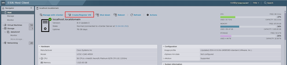
Step 2. From the main menu of the ESXi host client, choose Host.
Step 3. Click Create/ Register VM to initiate the wizard to create a new virtual machine.
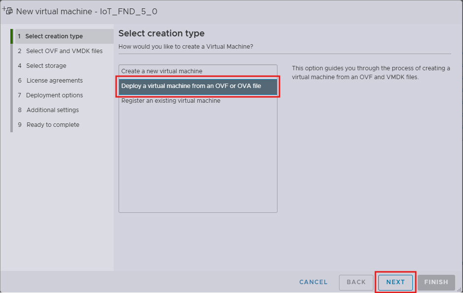
Step 4. In the step Select creation type, click Deploy a virtual machine from an OVF or OVA file.
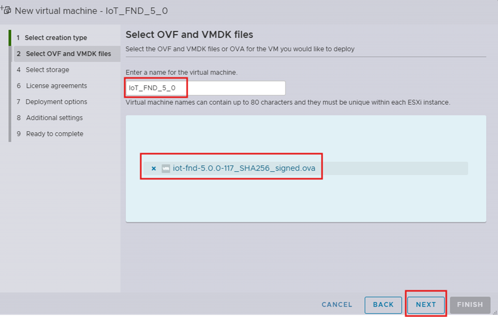
Step 5. In the step Select OVF and VMDK files:
i. Enter a name for the virtual machine.
ii. Attach the Cisco IoT FND OVA file.
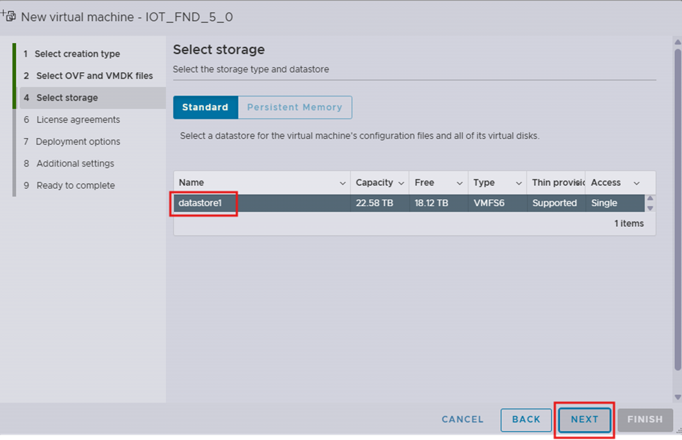
Step 6. In the step Select storage, choose a storage location for the virtual machine.
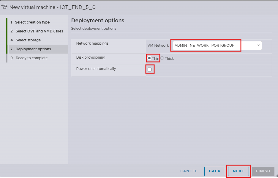
Step 7. In the step Deployment options:
i. In the Network mappings field, enter the port group that must be used for Admin Network SSH and GUI access (configuration item ADMIN_NETWORK_PORTGROUP).
ii. In the Data provisioning field, select Thin provisioning type.
iii. Unselect the Power on automatically option to avoid the VM from being powered on automatically after deployment.
Note: Thin Provisioning allows the VM disk to grow as needed.
Note: If the selected storage location does not have sufficient storage for the largest file installation option, a message displays noting insufficient storage. If the warning message appears, select another storage resource with greater capacity and click Next.
Step 8. Review the settings in step Ready to complete and click Finish.
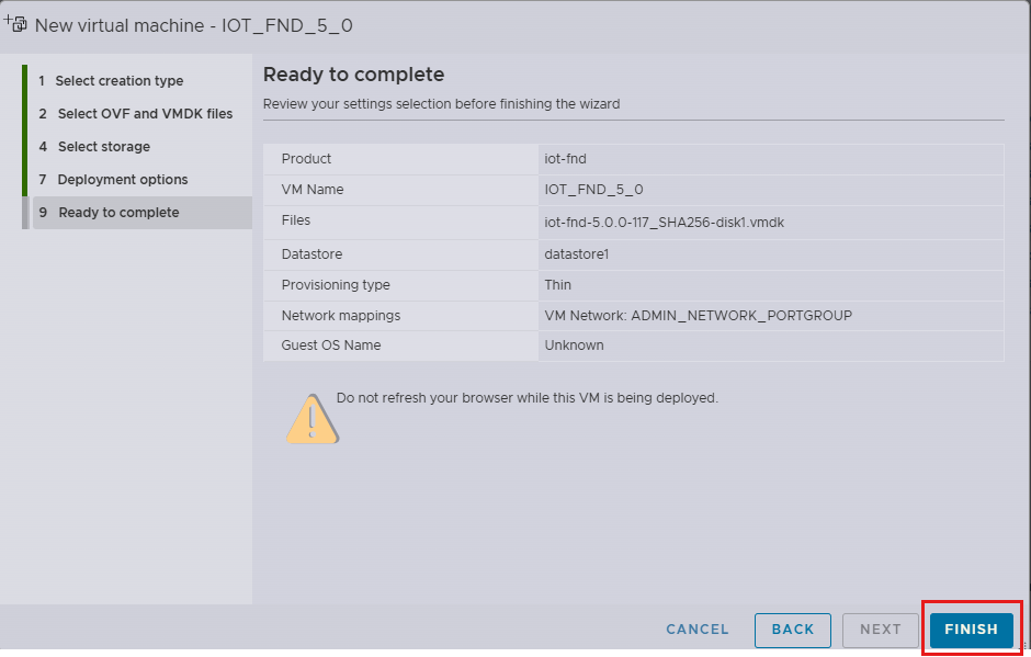
This completes the OVA deployment on ESXi, setting the foundation for further configuration and management of Cisco IoT FND, enabling robust network management capabilities.
Additional Changes to Cisco IoT FND VM before Power On
Before powering on the Cisco IoT FND virtual machine, certain configurations and adjustments are required to optimize performance and ensure compatibility with your network environment.
Step 1. Confirm that the deployment of the FND VM is fully complete. When the VM creation is complete, in the Recent tasks table, the Result column for the OVA deployment entry contains the value Completed Successfully.

Step 2. Check that the VM is currently powered off.
Step 3. To edit hardware configuration, in the EXSi host, select the Cisco IoT FND virtual machine and click Edit.
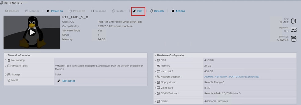
Step 4. In the Virtual Hardware tab, choose Add network adaptor.
Step 5. In the Network Adaptor 2 field, enter the port group that must be used for Corporate Data Network communications (configuration item CORP_DATA_NETWORK_PORTGROUP).
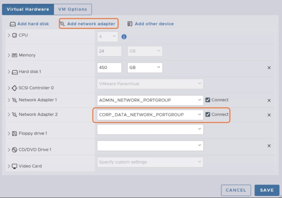
Step 6. Copy the MAC addresses for Network adaptor 1 and Network adaptor 2. Expand each section and note down the values in the MAC Address fields.
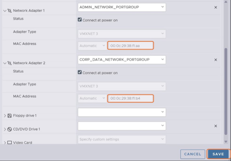
Step 7. Click Save.
Step 8. Power on the VM.
This completes verification of successful deployment of FND OVA image and other additional hardware changes required before powering on.
Map the NIC connection names that are required for Cisco IoT FND bringup and for integration with other necessary components.
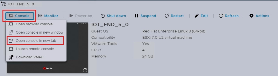
Step 1. Log into the ESXi host and select the Cisco IoT FND VM.
Step 2. Click Console and select Open Console in new tab.
The RHEL server launches. At first log in, the default credentials to use are:
Username: fnduser
Password: C!sco123
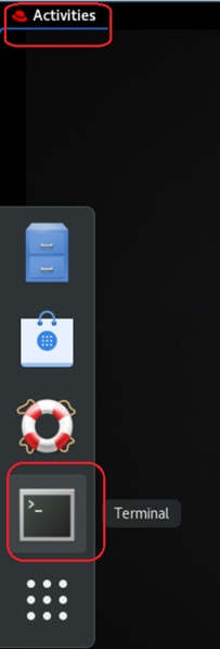
Step 3. After you log in, you are immediately prompted to change the default password.
Step 4. To access the terminal, click Activities and click the Terminal icon.
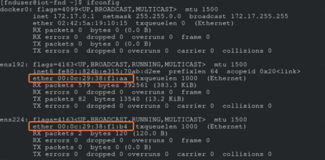
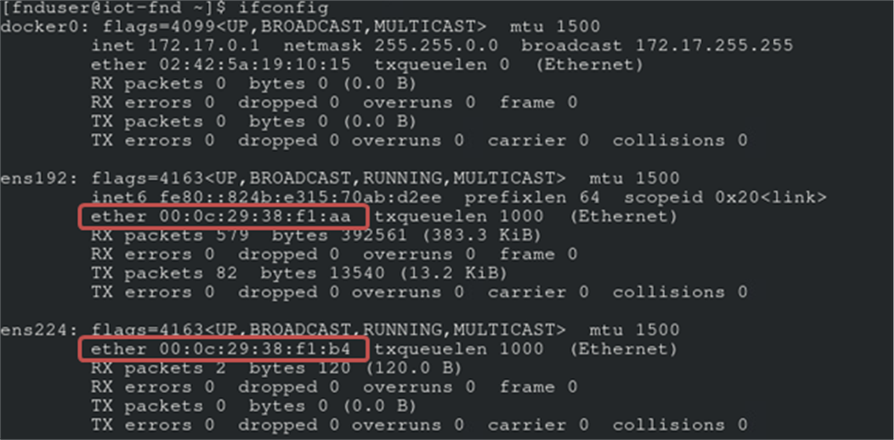
Step 5. Check and note down Network Connection names: Check existing NIC Devices using nmcli device status and ifconfig commands.
Note: Note down the device and connection name for the NICs to be configured. (ens192 and ens224 as per the example shown below)
Note: Check the MAC address of device using the ifconfig command and map the connection-names accordingly by referring to MAC Addresses noted down in ESXi in Step 6 of task Additional Changes to Cisco IoT FND VM before Power On.
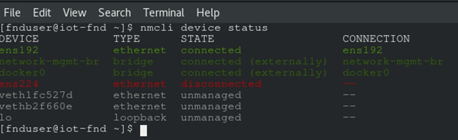
Step 6. For reference in later tasks, collect the details in a table. Here’s an example table based on the examples in this task.
Table 3. Cisco IoT FND device port mapping
| ESXi Portgroup Name |
MAC Address |
NMCLI Device Name |
NMCLI Connection Name |
| ADMIN_NETWORK_PORTGROUP |
00:0c:29:38:f1:aa |
ens192 |
ens192 (ADMIN_NETWORK_NMCLI_CONNECTION_NAME) |
| CORP_DATA_NETWORK_PORTGROUP |
00:0c:29:38:f1:b4 |
ens224 |
ens224 (CORP_DATA_NETWORK_PORTGROUP_CONNECTION_NAME) |
Bring up of FND using Shell configurations
This section explains the configurations required in Cisco IoT FND Shell after Power On for its bringup.
Network and system configurations
This section guides in basic setup like configuring Admin and Data Networks, hostname, NTP, and so on.
Table 4. Essential configuration items for network and system configurations
| Configuration Item |
Description |
| ADMIN_NETWORK_NMCLI_CONNECTION_NAME |
Admin Network connection name. Keep it same as the device name for simplicity. For example, eth0, ens192 etc. |
| CORP_DATA_NETWORK_NMCLI_CONNECTION_NAME |
Corporate Network Connection name . Keep it same as the device name for simplicity. For example, eth0, ens192 etc. |
| FND_ADMIN_NETWORK_IP |
IP Address for Cisco IoT FND Admin Network which is used for SSH and GUI access |
| FND_NMCLI_CONNECTION_NAME_TO_REACH_NTP |
Network Connection name to reach NTP. You can use ADMIN_NETWORK_NMCLI_CONNECTION_NAME or CORP_DATA_NETWORK_NMCLI_CONNECTION_NAME. |
| FND_CORP_DATA_NETWORK_IP |
IP Address of Cisco IoT FND in Corporate Data Network which is used for communication with HER, TPS, and field routers (via TPS or HER). |
| FND_HOST_NAME_FQDN |
Hostname of Cisco IoT FND, including domain name. |
| HER_CORP_DATA_NETWORK_IP |
IP Address of HER in Corporate Data Network which is used for communication with Cisco IoT FND. |
| NEXTHOP_TO_REACH_NTP_FROM_FND |
Nexthop IP address to reach NTP from Cisco IoT FND . |
| NTP_SERVER_1 |
Primary NTP server used for time synchronization. |
| NTP_SERVER_2 |
Backup NTP server used for time synchronization. |
| TPS_HOST_NAME_FQDN |
Hostname of TPS including domain name. |
| TPS_CORP_DATA_NETWORK_IP |
IP address of TPS in Corporate Data Network which is used to communicate with Cisco IoT FND. |
Step 1. Access the terminal of the Cisco IoT FND Shell.
Step 2. Start an interactive root shell session using the following command.
Example:
[fnduser@iot-fnd ~]# sudo -i
[sudo] password for fnduser: <Enter FND Shell Password>
[root@iot-fnd ~]#
Step 3. Network Adaptor connected to <ADMIN_NETWORK_PORTGROUP> (as noted down in Table 3) would already have connection-name. Use the following configuration to:
i. Set IPv4 method to manual
ii. Configure IPv4 address
iii. Bringup the interface by applying the changes
nmcli connection modify <ADMIN_NETWORK_NMCLI_CONNECTION_NAME> ipv4.addresses <FND_ADMIN_NETWORK_IP>/<subnet> ipv4.method manual
nmcli connection up <ADMIN_NETWORK_NMCLI_CONNECTION_NAME>
Example:
[root@iot-fnd ~]# nmcli connection modify ens192 ipv4.addresses 192.168.254.161/24 ipv4.method manual
[root@iot-fnd ~]# nmcli connection up ens192
Step 4. NIC with <CORP_DATA_NETWORK_PORTGROUP> (as noted down in Table 3) would not have connection-name. Add the connection and IP addresses using the following commands.
Note: This configuration assumes that <HER_CORP_DATA_NETWORK_IP> as the default gateway. It is recommended to have only one default gateway in the system. Consider adapting the gateway configurations based on your network environment.
nmcli nmcli connection add type ethernet ifname <CORP_DATA_NETWORK_NMCLI_CONNECTION_NAME> con-name <CORP_DATA_NETWORK_NMCLI_CONNECTION_NAME> ip4 <FND_CORP_DATA_NETWORK_IP>/<subnet> gw4 <HER_CORP_DATA_NETWORK_IP>
nmcli connection up <CORP_DATA_NETWORK_NMCLI_CONNECTION_NAME>
Example:
[root@iot-fnd ~]# nmcli connection add type ethernet ifname ens224 con-name ens224 ip4 192.168.103.100/24 gw4 192.168.103.102
[root@iot-fnd ~]# nmcli connection up ens224
Step 5. With the configured <FND_ADMIN_NETWORK_IP> IP address, SSH access can now be established from the servers in same subnet. Add appropriate static routes if SSH has to be done from servers that are not in the same subnet.
Step 1. Use the nmcli general hostname command to add the hostname.
[root@iot-fnd ~]# nmcli general hostname <FND_HOST_NAME_FQDN>
Step 2. Use the hostnamectl command to verify the configuration.
[root@iot-fnd ~]# hostnamectl
Step 1. To ensure primary and backup NTP servers are reachable, add the routes to reach them. Verify the added routes using ip route command.
[nmcli connection modify <FND_NMCLI_CONNECTION_NAME_TO_REACH_NTP> +ipv4.routes "<NTP_SERVER_1>/32 <NEXTHOP_TO_REACH_NTP_FROM_FND>"
nmcli connection modify <FND_NMCLI_CONNECTION_NAME_TO_REACH_NTP> +ipv4.routes "<NTP_SERVER_2>/32 <NEXTHOP_TO_REACH_NTP_FROM_FND>"
nmcli connection up <FND_NMCLI_CONNECTION_NAME_TO_REACH_NTP>
Example:
nmcli connection modify ens192 +ipv4.routes "1.0.0.101/32 192.168.1.1"
nmcli connection modify ens192 +ipv4.routes "1.0.0.102/32 192.168.1.1"
nmcli connection up ens192
ip route
Step 2. Backup the existing /etc/chrony.conf file before modifications.
[root@iot-fnd ~]# sudo cp /etc/chrony.conf /etc/chrony.conf.bak
Step 3. Comment existing default pool in the /etc/chrony.conf file.
[root@iot-fnd ~]# sudo sed -i '/^pool/s/^/#/' /etc/chrony.conf
Step 4. Add the primary and backup NTP Servers in the /etc/chrony.conf file.
[root@iot-fnd ~]# sudo sed -i '1i\server <NTP_SERVER_2> iburst' /etc/chrony.conf
[root@iot-fnd ~]# sudo sed -i '1i\server <NTP_SERVER_1> iburst' /etc/chrony.conf
Example:
[root@iot-fnd ~]# sudo sed -i '1i\server 1.0.0.102 iburst' /etc/chrony.conf
[root@iot-fnd ~]# sudo sed -i '1i\server 1.0.0.101 iburst' /etc/chrony.conf
Step 5. Verify the contents of the configuration file to check that both the NTP servers are added.
[root@iot-fnd ~]# cat /etc/chrony.conf | grep server
Step 6. Restart the chronyd service.
[fnduser@iot-fnd ~]# systemctl restart chronyd.service
[root@iot-fnd ~]# systemctl status chronyd.service
● chronyd.service - NTP client/server
Loaded: loaded (/usr/lib/systemd/system/chronyd.service; enabled; vendor preset: enabled)
Active: active (running) since Thu 2024-10-17 01:19:42 EDT; 29s ago
Docs: man:chronyd(8)
man:chrony.conf(5)
Process: 197485 ExecStopPost=/usr/libexec/chrony-helper remove-daemon-state (code=exited, status=0/SUCCESS)
Process: 200554 ExecStartPost=/usr/libexec/chrony-helper update-daemon (code=exited, status=0/SUCCESS)
Process: 200550 ExecStart=/usr/sbin/chronyd $OPTIONS (code=exited, status=0/SUCCESS)
Main PID: 200552 (chronyd)
Tasks: 1 (limit: 203710)
Memory: 1.0M
CGroup: /system.slice/chronyd.service
└─200552 /usr/sbin/chronyd
Step 7. It may take some time for NTP to synchronize. Wait for a while and then confirm if NTP synchronization is complete using the following commands.
[root@iot-fnd ~]# chronyc tracking
[root@iot-fnd ~]# chronyc sources
[root@iot-fnd ~]# timedatectl
Local time: Thu 2024-10-17 02:59:08 EDT
Universal time: Thu 2024-10-17 06:59:08 UTC
RTC time: Thu 2024-10-17 06:59:08
Time zone: America/New_York (EDT, -0400)
System clock synchronized: yes
NTP service: active
RTC in local TZ: no
[root@iot-fnd ~]#
Static name resolution for TPS domain name
Step 1. Map FQDN of TPS with its IP address in the /etc/hosts file.
[root@iot-fnd ~]$ sudo cp /etc/hosts /etc/hosts.bak
[root@iot-fnd ~]$ sudo sed -i ‘$a <TPS_CORP_DATA_NETWORK_IP> <TPS_HOST_NAME_FQDN>’ /etc/hosts
[root@iot-fnd ~]$ cat /etc/hosts
127.0.0.1 iot-fnd localhost localhost.localdomain localhost4 localhost4.localdomain4
::1 iot-fnd localhost localhost.localdomain localhost6 localhost6.localdomain6
<TPS_CORP_DATA_NETWORK_IP> <TPS_HOST_NAME_FQDN>
Configure PSK and IPAM in Cisco IoT FND Shell
Table 5. Essential configuration items for PSK and IPAM configurations
| Configuration Item |
Description |
| FND_CGMS_KEYSTORE |
CGMS keystore to be used for CISCO IoT FND |
| FND_KEYSTORE_PASSWORD |
Password of Cisco IoT FND CGMS Keystore
|
Step 1. Log into the Cisco IoT FND VM shell and carry out this task as a root user.
Step 2. Copy the CGMS keystore file. Use root user privileges to upload the cgms_keystore (FND_CGMS_KEYSTORE) file to the /opt/fnd/data/ directory. Backup existing cgms_keystore before upload.
[root@iot-fnd ~]$ cp /opt/fnd/data/cgms_keystore /opt/fnd/data/cgms_keystore.bak
[root@iot-fnd ~]# ls -lrt /opt/fnd/data/
[root@iot-fnd ~]$ scp <scp_user>@<scp_server>://<cgms_keystore_file_path> /opt/cgms-tpsproxy/conf/cgms_keystore
[root@iot-fnd ~]# ls -lrt /opt/fnd/data/
total 40
-rw-r--r-- 1 root root 1258 May 7 12:44 userPropertyTypes.xml
-rw-r--r-- 1 root root 1529 May 7 12:44 cisco-sudi-ca.pem
-rw-r--r-- 1 root root 4315 May 7 12:44 cgms_keystore.selfsigned
-rw------- 1 root root 518 May 8 06:03 fnd_psk.keystore
-rw-r--r-- 1 root root 9064 Oct 9 07:00 cgms_keystore
-rw------- 1 root root 270 Oct 9 07:02 cgms_backup.properties
-rw------- 1 root root 944 Oct 17 10:17 cgms.properties
Step 3. Check the status of the Cisco IoT FND container on the Linux host. The response should contain the value fnd-image: active.
[root@iot-fnd ~]# /opt/fnd/scripts/fnd-container.sh status
fnd-container is running, pid=2509
*** WARNING : deprecated key derivation used.
Using -iter or -pbkdf2 would be better.
CONTAINER ID NAME CPU % MEM USAGE / LIMIT MEM % NET I/O BLOCK I/O PIDS
e3d151c0c9ef fnd-container 2.61% 1.7GiB / 31.14GiB 5.46% 634MB / 599MB 1.2GB / 721kB 650
[root@iot-fnd ~]#
[root@iot-fnd ~]# docker container ls
CONTAINER ID IMAGE COMMAND CREATED STATUS PORTS NAMES
06fc10399064 fogd-image:active "/bin/sh -c /usr/loc…" 5 months ago Up 4 days 443/tcp
fogd-container
e3d151c0c9ef fnd-image:active "/bin/sh -c /opt/fnd…" 5 months ago Up 4 days 0.0.0.0:80->80/tcp, 0.0.0.0:162->162/udp, 0.0.0.0:443->443/tcp, 0.0.0.0:9120-9121->9120-9121/tcp, 0.0.0.0:5683->5683/udp, 0.0.0.0:61624-61626->61624-61626/udp, 0.0.0.0:9124-9125->9124-9125/tcp, 0.0.0.0:61628->61628/udp fnd-container
Tech tip: If the Cisco IoT FND container is not running, start the container using the /opt/fnd/scripts/fnd-container.sh start command.
Step 4. Encrypt the CGMS keystore password (FND_KEYSTORE_PASSWORD) in the Cisco IoT FND docker container. Copy the password value displayed.
[root@iot-fnd ~]# docker container exec fnd-container /opt/cgms/bin/encryption_util.sh encrypt <FND_KEYSTORE_PASSWORD>
7jlXPniVpMvat+TrDWqh1w==
Step 5. Update these parameters in the cgms.properties file.
| Parameters |
Value to add |
| cgms-keystore-password-hidden |
The encrypted password displayed in Step 4 of this task. |
|
● cgdm-tpsproxy-addr
● cgdm-tpsproxy-subject=CN
● proxy-bootstrap-ip
|
<TPS_HOST_NAME_FQDN> |
[root@iot-fnd ~]# cp /opt/fnd/data/cgms.properties /opt/fnd/data/cgms.properties.bak
[root@iot-fnd ~]# nano /opt/fnd/data/cgms.properties
[root@iot-fnd ~]# cat /opt/fnd/data/cgms.properties
cgms-keystore-password-hidden=7jlXPniVpMvat+TrDWqh1w==
fogd-ip=192.68.5.3
enable-reverse-dns-lookup=false
enableApiAuth=false
enable-bootstrap-service=true
cgdm-tpsproxy-addr=<TPS_HOST_NAME_FQDN>
cgdm-tpsproxy-subject=CN=<TPS_HOST_NAME_FQDN>
enable-bootstrap-service=true
pnp-server-port=9125
proxy-bootstrap-ip=<TPS_HOST_NAME_FQDN>
reload-during-bootstrap=false
optimizeTunnelProv=true
reprovision-timeout-minutes=30
#DEBUG_SSL=true
firmware-update-bootstrap=true
trust-device-server=true
Step 6. Restart the Cisco IoT FND container.
[root@iot-fnd ~]# /opt/fnd/scripts/fnd-container.sh restart
[root@iot-fnd ~]# /opt/fnd/scripts/fnd-container.sh status
fnd-container is running, pid=1237121
*** WARNING : deprecated key derivation used.
Using -iter or -pbkdf2 would be better.
CONTAINER ID NAME CPU % MEM USAGE / LIMIT MEM % NET I/O BLOCK I/O PIDS
e3d151c0c9ef fnd-container 3.17% 2.929GiB / 31.14GiB 9.40% 18.6MB / 13.7MB 8.19kB / 745kB 644
[root@iot-fnd ~]#
Step 7. Stop the Cisco IoT FND container and all its services. Check the status of the container, and if fnd-container is still active, stop the fnd service to make sure no processes are running.
[root@iot-fnd ~]# docker container exec fnd-container /opt/cgms/bin/cgms_status.sh
IoT-FND Version 5.0.0-117
10-14-2024 06:14:03 EDT: INFO: IoT-FND database server: 192.68.5.1
10-14-2024 06:14:04 EDT: INFO: IoT-FND database connection verified.
10-14-2024 06:14:04 EDT: INFO: IoT FND timeseries database server: 192.68.5.1
10-14-2024 06:14:04 EDT: INFO: IoT FND kapacitor server: 192.68.5.1
10-14-2024 06:14:05 EDT: INFO: IoT-FND timeseries database/kapacitor connection verified.
10-14-2024 06:14:07 EDT: INFO: IoT-FND application server is up and running.
10-13-2024 22:58:21 EDT: INFO: IoT-FND is up and running.
[root@iot-fnd ~]# docker container exec fnd-container /opt/cgms/bin/cgms_stop.sh
./jboss-cli.sh: line 59: setDefaultModularJvmOptions: command not found
[root@iot-fnd ~]# docker container exec fnd-container /opt/cgms/bin/cgms_status.sh
IoT-FND Version 5.0.0-117
10-13-2024 22:59:58 EDT: INFO: IoT-FND database server: 192.68.5.1
10-13-2024 22:59:58 EDT: INFO: IoT-FND database connection verified.
10-13-2024 22:59:58 EDT: INFO: IoT FND timeseries database server: 192.68.5.1
10-13-2024 22:59:58 EDT: INFO: IoT FND kapacitor server: 192.68.5.1
10-13-2024 22:59:59 EDT: INFO: IoT-FND timeseries database/kapacitor connection verified.
10-13-2024 23:00:01 EDT: ERROR: IoT-FND application server is not running.
[root@iot-fnd ~]#
Step 8. Run the setupCgms.sh script to configure IPAM and PSK settings.
Choose y for the following prompts:
i. Do you want to change IPAM and PSK Settings (y/n)?
ii. Do you want to use Internal IP Address Management (IPAM) (y/n)?
iii. Do you want to manage Tunnels using Unique Pre-Shared Keys (y/n)?
Choose n for all other prompts.
Note: The default database password is Cgms123.
[root@iot-fnd ~]# docker container exec -it fnd-container /opt/cgms/bin/setupCgms.sh
10-13-2024 23:09:48 EDT: INFO: ========== IoT-FND Setup Started - 2024-10-13-23-09-48 ==========
10-13-2024 23:09:48 EDT: INFO: Log file: /opt/cgms/bin/../server/cgms/log/cgms_setup.log
Are you sure you want to setup IoT-FND (y/n)? y
10-13-2024 23:10:01 EDT: INFO: User response: y
Do you want to change the database settings (y/n)? n
10-13-2024 23:10:08 EDT: INFO: User response: n
Do you want to change the database password (y/n)? n
10-13-2024 23:10:10 EDT: INFO: User response: n
Do you want to change the keystore password (y/n)? n
10-13-2024 23:10:13 EDT: INFO: User response: n
Do you want to change the web application 'root' user password (y/n)? n
10-13-2024 23:10:21 EDT: INFO: User response: n
Do you want to change IPAM and PSK Settings (y/n)? y
10-13-2024 23:10:41 EDT: INFO: User response: y
10-13-2024 23:10:41 EDT: INFO: Checking database connection. This may take a while. Please wait ...
10-13-2024 23:10:42 EDT: INFO: Database connection verification completed successfully
10-13-2024 23:10:42 EDT: INFO: Migrating IoT-FND database ...
Enter database password:Cgms123
10-13-2024 23:10:50 EDT: INFO: Log file: /opt/cgms/bin/../server/cgms/log/cgms_setup.log
10-13-2024 23:10:50 EDT: INFO: Performing migration. This may take a while. Please wait ...
10-13-2024 23:10:52 EDT: INFO: Migration completed.
10-13-2024 23:10:52 EDT: INFO: Performing post migration. This may take a while. Please wait ...
10-13-2024 23:10:57 EDT: INFO: Post migration completed.
10-13-2024 23:10:57 EDT: INFO: IoT-FND database migration completed successfully
Do you want to use Internal IP Address Management (IPAM) (y/n)? y
10-13-2024 23:11:05 EDT: INFO: User response: y
10-13-2024 23:11:05 EDT: INFO: Configuring Preferences settings for IPAM. This may take a while. Please wait...
10-13-2024 23:11:09 EDT: INFO: Preferences Settings for IPAM completed successfully
Do you want to manage Tunnels using Unique Pre-Shared Keys (y/n)? y
10-13-2024 23:11:18 EDT: INFO: User response: y
10-13-2024 23:11:18 EDT: INFO: Configuring Preferences settings for Tunnel Mgmt. This may take a while. Please wait...
10-13-2024 23:11:23 EDT: INFO: Preferences Settings for Tunnel Mgmt completed successfully
Do you want to change the FTP settings (y/n)? n
10-13-2024 23:11:28 EDT: INFO: User response: n
Do you want to change router CGDM protocol settings (y/n)? n
10-13-2024 23:11:50 EDT: INFO: User response: n
Do you want to change router management mode [Demo, Bandwidth Optimized, Default] (y/n)? n
10-13-2024 23:12:56 EDT: INFO: User response: n
Do you want to configure timeseries database (y/n)? n
10-13-2024 23:13:12 EDT: INFO: User response: n
10-13-2024 23:13:12 EDT: INFO: Configuring timeseries flag none in system properties. This may take a while. Please wait...
10-13-2024 23:13:12 EDT: INFO: timeseries flag none
Do you want to change log file settings)? (y/n)? n
10-13-2024 23:13:22 EDT: INFO: User response: n
10-13-2024 23:13:22 EDT: INFO: ========== IoT-FND Setup Completed Successfully ==========
Step 9. Restart the Cisco IoT FND container and check its status to confirm that the container is up and running for the configuration changes to take effect.
[root@iot-fnd ~]# /opt/fnd/scripts/fnd-container.sh restart
[root@iot-fnd ~]# /opt/fnd/scripts/fnd-container.sh status
fnd-container is running, pid=1237121
*** WARNING : deprecated key derivation used.
Using -iter or -pbkdf2 would be better.
CONTAINER ID NAME CPU % MEM USAGE / LIMIT MEM % NET I/O BLOCK I/O PIDS
e3d151c0c9ef fnd-container 3.17% 2.929GiB / 31.14GiB 9.40% 18.6MB / 13.7MB 8.19kB / 745kB 644
[root@iot-fnd ~]#
[root@iot-fnd ~]# docker container ls
CONTAINER ID IMAGE COMMAND CREATED STATUS PORTS NAMES
06fc10399064 fogd-image:active "/bin/sh -c /usr/loc…" 5 months ago Up 4 days 443/tcp fogd-container
e3d151c0c9ef fnd-image:active "/bin/sh -c /opt/fnd…" 5 months ago Up 6 minutes 0.0.0.0:80->80/tcp, 0.0.0.0:162->162/udp, 0.0.0.0:443->443/tcp, 0.0.0.0:9120-9121->9120-9121/tcp, 0.0.0.0:5683->5683/udp, 0.0.0.0:61624-61626->61624-61626/udp, 0.0.0.0:9124-9125->9124-9125/tcp, 0.0.0.0:61628->61628/udp fnd-container
[root@iot-fnd ~]#
[root@iot-fnd ~]# docker container exec fnd-container /opt/cgms/bin/cgms_status.sh
IoT-FND Version 5.0.0-117
10-14-2024 06:14:03 EDT: INFO: IoT-FND database server: 192.68.5.1
10-14-2024 06:14:04 EDT: INFO: IoT-FND database connection verified.
10-14-2024 06:14:04 EDT: INFO: IoT FND timeseries database server: 192.68.5.1
10-14-2024 06:14:04 EDT: INFO: IoT FND kapacitor server: 192.68.5.1
10-14-2024 06:14:05 EDT: INFO: IoT-FND timeseries database/kapacitor connection verified. 10-14-2024 06:14:05 EDT: INFO: IoT-FND application server is up and running.
Access Cisco IoT FND GUI
After the Cisco IoT FND container and the service are up and running, you can access the Cisco IoT FND GUI.
Step 1. In a web browser, enter one of the following URLs:
● https://<FND_ADMIN_NETWORK_IP>
● https://<FND_CORP_DATA_NETWORK_IP>
Step 2. At first login, use the following credentials:
Username: root
Password: root123
Step 3. After the first login, change your password immediately.
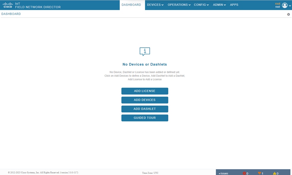
At this stage, the network and essential system configurations, including NTP, hostname, and static name resolution, are finalized. Additionally, configurations for tunnel management using a unique Pre-Shared Key (PSK) and IPAM are complete. The Cisco IoT FND GUI should now be accessible. The subsequent sections guide you through integrating additional components that are necessary for successful PnP and ZTD.
Integrate TPS with Cisco IoT FND
A TPS (also referred as TPS Proxy) takes in the communication from the untrusted part of the network and proxies the communication to Cisco IoT FND which is located in a trusted part of the network.
Table 6. Configuration items for TPS VM creation
| Configuration item |
Description |
| ADMIN_NETWORK_PORTGROUP |
ESXi Port group that will be used for Admin Network for SSH and GUI access. |
| CORP_DATA_NETWORK_PORTGROUP |
ESXi Port group that will be used for Corporate Data Network for the communication of Cisco IoT FND with HER, TPS and field router (via TPS or HER). |
| DMZ_FIELD_ROUTER_FACING_NETWORK_PORTGROUP |
ESXi Port group that will be used for communication with field router over DMZ. |
| DMZ_FIELD_ROUTER_FACING_NETWORK_NMCLI_CONNECTION_NAME
|
DMZ field-router-facing network’s connection name. Keep it same as the device name for simplicity. For example, eth0, ens192, and so on. |
| ESXI_HOST_PASSWORD |
Password to access the ESXi host. |
| ESXI_HOST_URL |
IP Address of the ESXi host (version 6.5 and above) where the Cisco IoT FND VM is deployed. |
| ESXI_HOST_USERNAME |
Username to access the ESXi host. |
| FND_HOST_NAME_FQDN |
Hostname of Cisco IoT FND including domain name. |
| FND_CORP_DATA_NETWORK_IP |
IP Address for Cisco IoT FND Corporate Data Network which is used for communication with HER and TPS. |
| NEXTHOP_TO_REACH_NTP_FROM_TPS |
Nexthop IP to reach NTP from TPS. |
| NTP_SERVER_1 |
Primary NTP server used for Time synchronization. |
| NTP_SERVER_2 |
Backup NTP server used for time synchronization. |
| TPS_HOST_NAME_FQDN |
Hostname of TPS including domain name. |
| TPS_ADMIN_NETWORK_IP |
IP address for TPS Admin Network which is used for SSH and GUI access. |
| TPS_CGMS_KEYSTORE |
TPS CGMS keystore file. |
| TPS_NMCLI_CONNECTION_NAME_TO_REACH_NTP |
Network Connection name to reach NTP. The value could be ADMIN_NETWORK_NMCLI_CONNECTION_NAME or CORP_DATA_NETWORK_NMCLI_CONNECTION_NAME |
| TPS_CORP_DATA_NETWORK_IP |
IP address for TPS data network which is used to communicate over Corporate Data Network with Cisco IoT FND. |
| TPS_DMZ_FIELD_ROUTER_FACING _NETWORK _GATEWAY |
Gateway of field-router-facing network. |
| TPS_DMZ_FIELD_ROUTER_FACING_NETWORK _IP |
IP Address for TPS field-router-facing network used for communication with field router. |
| TPS_KEYSTORE_PASSWORD |
Password protecting the TPS keystore. |
| TPS_OVA_IMAGE |
TPS OVA image. |
Step 1. Upload the TPS OVA file using the steps detailed in the task Import Cisco IoT FND OVA file into an ESXi host.
Step 2. In the EXSi host, select the TPS virtual machine.
Step 3. Click Edit.
Step 4. In the Virtual Hardware tab, choose Add network adaptor.
Step 5. Add three network adaptors: <ADMIN_NETWORK_PORTGROUP>, <CORP_DATA_NETWORK_PORTGROUP>, and <DMZ_FIELD_ROUTER_FACING_NETWORK_PORTGROUP>.
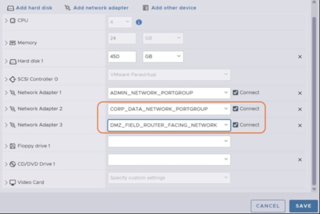
Step 6. Power on the TPS VM.
Step 7. To map the NICs and their connection names, for the TPS VM, carry out the steps detailed in the task Map NIC connection names.
Here’s an example table for you to fill out.
Table 7. TPS device port mappings
| ESXi Portgroup Name |
MAC Address |
NMCLI Device Name |
NMCLI Connection Name |
| ADMIN_NETWORK_PORTGROUP |
<Enter the IP address> |
<Enter device name> |
<Enter connection name> (ADMIN_NETWORK_NMCLI_CONNECTION_NAME) |
| CORP_DATA_NETWORK_PORTGROUP |
<Enter the IP address> |
<Enter device name> |
<Enter connection name> (CORP_DATA_NETWORK_PORTGROUP_CONNECTION_NAME) |
| DMZ_FIELD_ROUTER_FACING_NETWORK_PORTGROUP |
<Enter the IP address> |
<Enter device name> |
<Enter connection name> (DMZ_FIELD_ROUTER_FACING_NETWORK_NMCLI_CONNECTION_NAME) |
Configure TPS network settings
Step 1. In the ESXi client, click Console.
Step 2. Select Open Console in new tab.
Step 3. Log into the TPS VM console using the following default credentials:
Username: root
Password: C!sco123
Step 4. Change the password after the first login.
Step 5. Click Applications, and choose System Tools > Terminal.
Step 6. Check existing NIC Devices using the nmcli device status and ifconfig commands.
Step 7. NIC with <ADMIN_NETWORK_PORTGROUP> would already have connection-name. Modify the connection using the nmcli connection modify command.
nmcli connection modify <ADMIN_NETWORK_NMCLI_CONNECTION_NAME> ipv4.addresses <TPS_ADMIN_NETWORK_IP>/<subnet> ipv4.method manual
nmcli connection up <ADMIN_NETWORK_NMCLI_CONNECTION_NAME>
Step 8. With the configured <TPS_ADMIN_NETWORK_IP> IP address, you can now establish SSH access from the local subnet. For SSH access from other subnets, enable static routes for reachability.
Step 9. For the NICs CORP_DATA_NETWORK_PORTGROUP and DMZ_FIELD_ROUTER_FACING_NETWORK_PORTGROUP, add the connections and IP addresses.
Note: This configuration assumes that <TPS_DMZ_FIELD_ROUTER_FACING_NETWORK_GATEWAY> as the default gateway. It is recommended to have only one default gateway in the system. Consider adapting the gateway configurations based on your network environment.
nmcli connection add type ethernet ifname <CORP_DATA_NETWORK_NMCLI_CONNECTION_NAME> con-name <CORP_DATA_NETWORK_NMCLI_CONNECTION_NAME> ip4 <TPS_CORP_DATA_NETWORK_IP>/<subnet>
nmcli connection add type ethernet ifname <DMZ_FIELD_ROUTER_FACING_NETWORK_NMCLI_CONNECTION_NAME> con-name <DMZ_FIELD_ROUTER_FACING_NETWORK_NMCLI_CONNECTION_NAME> ip4 <TPS_DMZ_FIELD_ROUTER_FACING_NETWORK_IP>/<subnet> gw4 <TPS_DMZ_FIELD_ROUTER_FACING_NETWORK_GATEWAY>
nmcli connection up <CORP_DATA_NETWORK_NMCLI_CONNECTION_NAME>
nmcli connection up <DMZ_FIELD_ROUTER_FACING_NETWORK_NMCLI_CONNECTION_NAME>
Step 10. Use the nmcli general hostname <> command to configure the hostname and the hostnamectl command to verify that the configured hostname is saved.
[root@iot-tps ~]# nmcli general hostname <TPS_HOST_NAME_FQDN>
[root@iot-tps ~]# hostnamectl
Step 1. Use the following commands to add the routes to primary and backup NTP servers.
[root@iot-tps ~]# nmcli connection modify <TPS_NMCLI_CONNECTION_NAME_TO_REACH_NTP> +ipv4.routes "<NTP_SERVER_1>/32 <NEXTHOP_TO_REACH_NTP_FROM_TPS>"
[root@iot-tps ~]# nmcli connection modify <TPS_NMCLI_CONNECTION_NAME_TO_REACH_NTP> +ipv4.routes "<NTP_SERVER_2>/32 <NEXTHOP_TO_REACH_NTP_FROM_TPS>"
[root@iot-tps ~]# nmcli connection up <TPS_NMCLI_CONNECTION_NAME_TO_REACH_NTP>
Example:
nmcli connection modify ens192 +ipv4.routes "1.0.0.101/32 192.168.1.1"
nmcli connection modify ens192 +ipv4.routes "1.0.0.102/32 192.168.1.1"
nmcli connection up ens192
ip route
Step 2. Backup the existing /etc/chrony.conf file.
[root@iot-tps ~]# cp /etc/chrony.conf /etc/chrony.conf.bak
Step 3. Comment the existing default pool in the configuration file.
[root@iot-tps ~]# sed -i '/^pool/s/^/#/' /etc/chrony.conf
Step 4. Add the primary and backup NTP servers in the configuration file.
[root@iot-tps ~]# sed -i '1i\server <NTP_SERVER_2> iburst' /etc/chrony.conf
[root@iot-tps ~]# sed -i '1i\server <NTP_SERVER_1> iburst' /etc/chrony.conf
Example:
[root@iot-tps ~]# sed -i '1i\server 1.0.0.102 iburst' /etc/chrony.conf
[root@iot-tps ~]# sed -i '1i\server 1.0.0.101 iburst' /etc/chrony.conf
Step 5. Verify the contents of the file to ensure that the changes are saved.
[root@iot-tps ~]# more /etc/chrony.conf
Step 6. Restart chronyd service.
[root@iot-tps ~]# systemctl restart chronyd.service
[root@iot-tps ~]# systemctl status chronyd.service
● chronyd.service - NTP client/server
Loaded: loaded (/usr/lib/systemd/system/chronyd.service; enabled; vendor preset: enabled)
Active: active (running) since Thu 2024-10-17 01:19:42 EDT; 29s ago
Docs: man:chronyd(8)
man:chrony.conf(5)
Process: 197485 ExecStopPost=/usr/libexec/chrony-helper remove-daemon-state (code=exited, status=0/SUCCESS)
Process: 200554 ExecStartPost=/usr/libexec/chrony-helper update-daemon (code=exited, status=0/SUCCESS)
Process: 200550 ExecStart=/usr/sbin/chronyd $OPTIONS (code=exited, status=0/SUCCESS)
Main PID: 200552 (chronyd)
Tasks: 1 (limit: 203710)
Memory: 1.0M
CGroup: /system.slice/chronyd.service
└─200552 /usr/sbin/chronyd
Step 7. To verify NTP synchronization, use the following commands. Note that it may take some time for the synchronization to complete. The value System clock synchronized: yes in the response confirms that the NTP synchronization is complete.
[root@iot-tps ~]# chronyc tracking
[root@iot-tps ~]# chronyc sources
[root@iot-tps ~]# timedatectl
Local time: Thu 2024-10-17 02:59:08 EDT
Universal time: Thu 2024-10-17 06:59:08 UTC
RTC time: Thu 2024-10-17 06:59:08
Time zone: America/New_York (EDT, -0400)
System clock synchronized: yes
NTP service: active
RTC in local TZ: no
[root@iot-tps ~]#
Configure static name resolution
Step 1. Map FQDN of FND with its IP in the /etc/hosts file.
[root@iot-tps ~]$ cp /etc/hosts /etc/hosts.bak
[root@iot-tps ~]$ sed -i '$a <FND_CORP_DATA_NETWORK_IP> <FND_HOST_NAME_FQDN>' /etc/hosts
[root@iot-tps ~]$ cat /etc/hosts
127.0.0.1 iot-tps localhost localhost.localdomain localhost4 localhost4.localdomain4
::1 iot-tps localhost localhost.localdomain localhost6 localhost6.localdomain6
<FND_CORP_DATA_NETWORK_IP> <FND_HOST_NAME_FQDN>
Update CGMS keystore and TPS proxy properties
Step 1. Use root user privileges to upload cgms_keystore (<TPS_CGMS_KEYSTORE>) file to the /opt/cgms-tpsproxy/conf/ directory. Backup existing cgms_keystore before upload.
[root@iot-tps ~]$ cp /opt/cgms-tpsproxy/conf/cgms_keystore /opt/cgms-tpsproxy/conf/cgms_keystore.bak
[root@iot-tps ~]$ scp <scp_user>@<scp_server>://<cgms_keystore_file_path> /opt/cgms-tpsproxy/conf/cgms_keystore
Step 2. Encrypt the CGMS keystore password and copy the displayed encrypted password.
[root@iot-tps bin]# /opt/cgms-tpsproxy/bin/encryption_util.sh encrypt <TPS_KEYSTORE_PASSWORD>
yJ7v/eijrPT9a3B/otHDoffVfMmz6at5JBDtFrb4EtMif+mo
Step 3. In the /opt/cgms-tpsproxy/conf/tpsproxy.properties file, update the following properties
| Property |
Value |
|
● Inbound proxy destination
● Outbound proxy allowed addresses
● Inbound bsproxy destination
|
<FND_HOST_NAME_FQDN> |
| CGMS keystore encrypted password
|
The encrypted password from step 3 |
root@iot-tps ~]# nano /opt/cgms-tpsproxy/conf/tpsproxy.properties
[root@iot-tps ~]# more /opt/cgms-tpsproxy/conf/tpsproxy.properties
inbound-proxy-destination=https://<FND_HOST_NAME_FQDN>:9120
outbound-proxy-allowed-addresses=<FND_HOST_NAME_FQDN>
cgms-keystore-password-hidden=yJ7v/eijrPT9a3B/otHDoffVfMmz6at5JBDtFrb4EtMif+mo
inbound-bsproxy-destination=http://<FND_HOST_NAME_FQDN>:9125
enable-bootstrap-service=true
bootstrap-proxy-listen-port=9125
enable-reverse-dns-lookup=false
Step 4. Start the TPS proxy service.
[root@iot-tps conf]# systemctl start tpsproxy.service
Step 5. Verify that the TPS proxy service is running. The value Active: active (running) in the response confirms that the service is running.
[root@iot-tps bin]# systemctl status tpsproxy.service
● tpsproxy.service - SYSV: CGMS Tunnel Provisioning proxy server
Loaded: loaded (/etc/rc.d/init.d/tpsproxy; generated)
Active: active (running) since Thu 2025-03-06 06:19:57 EST; 1min 31s ago
Docs: man:systemd-sysv-generator(8)
Process: 4278 ExecStart=/etc/rc.d/init.d/tpsproxy start (code=exited, status=0/SUCCESS)
Tasks: 39 (limit: 152110)
Memory: 68.2M
CGroup: /system.slice/tpsproxy.service
└─4296 java -server -Xms128m -Xmx2g -XX:MaxPermSize=256m -server -XX:+HeapDumpOnOutOfMemoryError -XX:HeapDumpPath=/opt/cgms-tpsproxy/log -XX:-OmitStackTraceInFastThrow -XX:-UseP>
Mar 06 06:19:56 tps-san.ipg.cisco.com systemd[1]: Starting SYSV: CGMS Tunnel Provisioning proxy server...
Mar 06 06:19:56 tps-san.ipg.cisco.com runuser[4294]: pam_unix(runuser:session): session opened for user root by (uid=0)
Mar 06 06:19:56 tps-san.ipg.cisco.com runuser[4294]: pam_unix(runuser:session): session closed for user root
Mar 06 06:19:57 tps-san.ipg.cisco.com tpsproxy[4278]: [36B blob data]
Mar 06 06:19:57 tps-san.ipg.cisco.com systemd[1]: Started SYSV: CGMS Tunnel Provisioning proxy server.
[root@iot-tps ~]# ss -tulwn | grep LISTEN
tcp LISTEN 0 128 0.0.0.0:22 0.0.0.0:*
tcp LISTEN 0 5 127.0.0.1:631 0.0.0.0:*
tcp LISTEN 0 128 [::]:22 [::]:*
tcp LISTEN 0 5 [::1]:631 [::]:*
tcp LISTEN 0 50 *:9120 *:*
tcp LISTEN 0 50 *:9122 *:*
tcp LISTEN 0 50 *:9125 *:*
By following the steps outlined in the previous sections, the TPS OVA deployment completes successfully, and the TPS shell is accessible. All necessary configurations within TPS are finalized, ensuring successful integration with Cisco IoT FND.
Integrate HER with Cisco IoT FND
After the field router is bootstrapped successfully, to ensure secure communication of field routers with Cisco IoT FND, OT applications like SCADA and so on, IPSec tunnels (based on pre-shared key) are established between field router and HER. The HER can be positioned in Network Operation Centre or Control Centre/DSO.
This section provides a guide on the steps necessary to configure HER using the Cisco Catalyst 8000 platform.
Table 8. Essential configuration items for HER integration
| Configuration item |
Description |
| DOMAIN_NAME |
Domain name used across the network. |
| HER_ADMIN_NETWORK_IP |
IP Address for HER Admin Network which is used for SSH access. |
| HER_CORP_DATA_NETWORK_IP |
IP Address configured on the Corporate Data Network interface which is used for communication with Cisco IoT FND. |
| HER_DMZ_FIELD_ROUTER_FACING_NETWORK_IP |
IP Address configured on the field-router-facing interface. |
| HER_DMZ_FIELD_ROUTER_FACING_NETWORK_GATEWAY |
Nexthop IP address on HER in DMZ_FIELD_ROUTER_FACING_NETWORK. |
| HER_HOST_NAME |
Hostname of HER, also used as local key-id on HER and remote key-id on field router for PSK based key-rings in this guide. |
| HER_LOOPBACK_IP |
IP Address of HER’s loopback interface. |
| HER_PASSWORD |
Password for accessing HER. |
| HER_USERNAME |
Username for accessing HER. |
| NEXTHOP_TO_REACH_NTP_FROM_HER |
Nexthop IP to reach NTP server from HER. |
| IPSEC_TRANSFORM_SET_MODE |
IPSec Transform-set mode can be either transport or tunnel. Configure it based on the network design. |
| IP_MTU |
Maximum IPv4 MTU supported between field router and DMZ Network through the Provider network. See the Appendix section for calculation reference. |
| TCP_MSS |
Maximum IPv4 segment size supported between field router and DMZ Network through the provider network. See the Appendix section for calculation reference. |
Note: We assume that the HER router is up and running, and can be accessed.
Step 1. Connect to the HER console.
Step 2. To enable device SSH access, configure the Admin Network interface, user credentials, and AAA configuration.
conf t
interface GigabitEthernet1
description ADMIN Network
ip address <HER_ADMIN_NETWORK_IP> <subnet>
no shut
!
username <HER_USERNAME> privilege 15 secret <HER_PASSWORD>
enable password <HER_PASSWORD>
!
aaa new-model
!
end
write
Step 3. Configure IP address on the interfaces that are part of Corporate Data and DMZ field-router-facing networks.
conf t
interface GigabitEthernet2
description FND_TPS_HER_Network
ip address <HER_CORP_DATA_NETWORK_IP> <subnet_mask>
no shutdown
!
!Field Router Facing Interface used as Tunnel Source
interface GigabitEthernet3
description Field Router Facing Network
ip address <HER_DMZ_FIELD_ROUTER_FACING_NETWORK_IP> <subnet_mask>
no shutdown
!
ip route 0.0.0.0 0.0.0.0 <HER_DMZ_FIELD_ROUTER_FACING_NETWORK _GATEWAY>
end
write
Step 4. Verify the changes using the ip interface brief command.
Router#show ip interface brief
Interface IP-Address OK? Method Status Protocol
GigabitEthernet1 <HER_ADMIN_NETWORK_IP> YES NVRAM up up
GigabitEthernet2 <HER_CORP_DATA_NETWORK_IP> YES NVRAM up up
GigabitEthernet3 <HER_DMZ_FIELD_ROUTER_FACING_NETWORK_IP> YES NVRAM up up
Step 5. Use the ping command to verify that Cisco IoT FND is reachable over Corporate Data Network.
Router#ping <FND_CORP_DATA_NETWORK_IP>
Type escape sequence to abort.
Sending 5, 100-byte ICMP Echos to <FND_CORP_DATA_NETWORK_IP>, timeout is 2 seconds:
!!!!!
Success rate is 100 percent (5/5), round-trip min/avg/max = 1/1/1 ms
Step 6. Enable the Network Advantage license and reload.
conf t
license accept end user agreement
license boot level network-advantage addon dna-advantage
end
write
reload
Step 1. Use the following commands to add NTP configurations.
conf t
!
ip route <NTP_SERVER_1> 255.255.255.255 <NEXTHOP_TO_REACH_NTP_FROM_HER>
ip route <NTP_SERVER_2> 255.255.255.255 <NEXTHOP_TO_REACH_NTP_FROM_HER>
!
ntp server <NTP_SERVER_1> prefer
ntp server <NTP_SERVER_2>
!
end
write
Step 2. Use the show ntp associations command to verify the status of NTP peers.
Router#show ntp associations
address ref clock st when poll reach delay offset disp
*~<NTP_SERVER_1> .GNSS. 1 140 1024 377 1.620 -2.905 1.030
~<NTP_SERVER_2> .TIME. 16 61 64 0 0.000 0.000 15937.
* sys.peer, # selected, + candidate, - outlyer, x falseticker, ~ configured
Step 3. Use the show ntp status command to verify synchronization status. The value Clock is synchronized in the response verifies that the process is complete.
Router#show ntp status
Clock is synchronized, stratum 2, reference is <NTP_SERVER_1>
nominal freq is 250.0000 Hz, actual freq is 249.9967 Hz, precision is 2**10
ntp uptime is 48501300 (1/100 of seconds), resolution is 4016
reference time is EB7B82A3.E7EFA030 (09:18:51.906 IST Wed Mar 12 2025)
clock offset is -2.9053 msec, root delay is 1.62 msec
root dispersion is 7.07 msec, peer dispersion is 1.03 msec
loopfilter state is 'CTRL' (Normal Controlled Loop), drift is 0.000013263 s/s
system poll interval is 1024, last update was 145 sec ago.
Step 1. Add general configurations.
conf t
!Hostname
hostname <HER_HOST_NAME>
!AAA Configurations
aaa group server radius FARAuthList
server name fanheradius
aaa authentication login default local
aaa authorization console
aaa authorization exec default local
aaa authorization network FARAuthList group radius
aaa authorization network FlexVPN-Config local
aaa authorization network FlexVPN_Author local
!
aaa session-id common
!Domain Configurations
no ip domain lookup
ip domain name <DOMAIN_NAME>
!
!Other General Settings
ip forward-protocol nd
ip tcp mss <TCP_MSS>
ip tcp synwait-time 5
ip tcp path-mtu-discovery
no ip http server
ip http authentication local
no ip http secure-server
ip http secure-active-session-modules none
ip http active-session-modules none
!
ip ssh version 2
!
netconf max-sessions 16
netconf ssh
!
end
write
Step 2. Configure IKEv2 and tunnel-related settings to bringup a PSK-based tunnel with the field router.
conf t
!Loopback Configurations
interface Loopback0
ip address <HER_LOOPBACK_IP> 255.255.255.255
!
!Access-List for FND prefix advertisement to Field Router
ip access-list standard ADVERTISE_TO_FAR_ACL
10 permit <FND_CORP_DATA_NETWORK_IP> <wild_card_mask>
!
!IKEv2 Author Policy configs
crypto ikev2 authorization policy FlexVPN_Author_Policy
route set interface Loopback0
route set access-list ADVERTISE_TO_FAR_ACL
!
!IKEv2 Proposal configs
crypto ikev2 redirect client
crypto ikev2 proposal FlexVPN_IKEv2_Proposal
encryption aes-cbc-256
integrity sha256
group 14
!
!IKEv2 Policy configs
crypto ikev2 policy FlexVPN_IKEv2_Policy
proposal FlexVPN_IKEv2_Proposal
!
!IKEv2 keyring configuration (peer configs and corresponding keys) is updated by FND
crypto ikev2 keyring FlexVPN_Keyring
!
crypto ikev2 profile FlexVPN_IKEv2_Profile
match identity remote fqdn domain <DOMAIN_NAME>
!Use local key-id as per your requirement, make sure to update the same in FND Router Tunnel Addition Template
identity local key-id <HER_HOST_NAME>
authentication remote pre-share
authentication local pre-share
keyring local FlexVPN_Keyring
dpd 30 3 periodic
aaa authorization group psk list FlexVPN_Author FlexVPN_Author_Policy
virtual-template 1
!
!IPSec Policy configs
crypto isakmp invalid-spi-recovery
!
crypto ipsec transform-set FlexVPN_IPsec_Transform_Set esp-aes esp-sha256-hmac
mode <IPSEC_TRANSFORM_SET_MODE>
!
crypto ipsec profile FlexVPN_IPsec_Profile
set transform-set FlexVPN_IPsec_Transform_Set
set pfs group14
set ikev2-profile FlexVPN_IKEv2_Profile
responder-only
!
!Virtual-Template configs
interface Virtual-Template1 type tunnel
ip unnumbered Loopback0
ip mtu <IP_MTU>
ip tcp adjust-mss <TCP_MSS>
tunnel source GigabitEthernet3 !Field Router Facing Interface used as Tunnel Source
tunnel protection ipsec profile FlexVPN_IPsec_Profile
!
end
write
Carry out the following tasks in the Cisco IoT FND GUI :
1. Add HER and field routers to Cisco IoT FND using CSV files
2. Configure Cisco IoT FND provisioning settings for bootstrapping and ZTD
3. Add subnets used for IPAM
Table 9. Configuration items for adding HER and field routers to Cisco IoT FND
| Configuration item |
Description |
| FIELD_ROUTER_PASSWORD |
Password used by Cisco IoT FND for accessing the field router. |
| FIELD_ROUTER_SERIAL_NUMBER |
Serial number of field router. |
| FIELD_ROUTER_TUNNEL_SOURCE_INTERFACE |
Source interface of tunnel from field router to HER. |
| FIELD_ROUTER_USERNAME |
Username of rield router. |
| FIELD_ROUTER_V4_LOOPBACK_IP |
Loopback IP to be used for field router, if IPAM feature is not used. |
| FND_HOST_NAME_FQDN |
Hostname of Cisco IoT FND including domain name. |
| HER_DMZ_FIELD_ROUTER_FACING_NETWORK_IP |
IP address configured on HER for field-router-facing network interface. |
| HER_HOST_NAME |
Hostname of HER, also used as local key-id on HER and remote key-id on field router for PSK-based key rings. |
| HER_LOOPBACK_IP |
IP Address of HER’s loopback interface for accessing from Cisco IoT FND. |
| HER_EID |
EID of HER to be added using CSV. It is recommended to use <Platform>+<SerialNumber> which can be fetched using the show license udi command. For example, C8000V+ 9Z2CEK3YBQ9. |
| HER_PASSWORD |
Password for accessing HER from Cisco IoT FND. |
| HER_USERNAME |
Username for accessing HER from Cisco IoT FND. |
| TPS_HOST_NAME_FQDN |
Hostname of TPS including domain name. |
Step 1. Create a CSV file with the necessary parameters for the HER.
eid,deviceType,ip,netconfUsername,netconfPassword
<HER_EID>,c8000,<HER_CORP_DATA_NETWORK_IP>,<HER_USERNAME>,<HER_PASSWORD>
For example:
eid,deviceType,ip,netconfUsername,netconfPassword
C8000V+9Z2CEK3YBQ9,c8000,192.168.103.102,her-admin,her-password
C8000V+9Z2CEK3YBJ8,c8000,192.168.103.103,her-admin,her-password
C8000V+9Z2CEK3YBI7,c8000,192.168.103.104,her-admin,her-password
Step 2. Log into Cisco IoT FND.
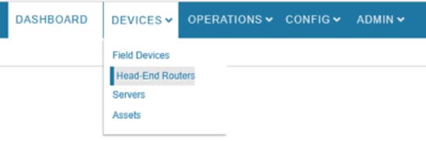
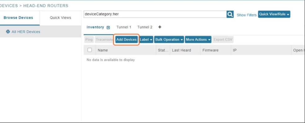
Step 3. From the main menu, choose Devices > Head-End Routers.
Step 4. Click Add Devices.
Step 5. In the CSV/XML file field, upload the CSV file you created.
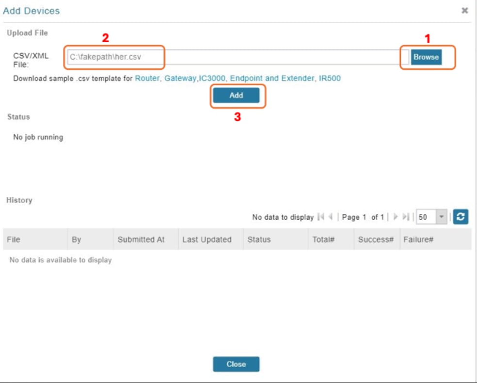
When the upload is complete, in the Add Devices page, the History table displays the status of the file upload as Completed. The table entry also displays the total number of routers in the CSV, and the number of successful and failed uploads.
Add field routers to Cisco IoT FND
Step 1. Create a CSV file with the required parameters for the field area routers, using the following examples.
a. If you do not use the IPAM feature, to use a specific loopback address (assigned manually), use the loopbackv4Address or loopbackv6Address columns in the CSV file.
deviceType,eid,loopbackv4Address,tunnelSrcInterface1,ipsecTunnelDestAddr1,tunnelHerEid,adminUsername,adminPassword
ir1100,IR1101-K9+<FIELD_ROUTER_SERIAL_NUMBER>,<FIELD_ROUTER_V4_LOOPBACK_IP>,<FIELD_ROUTER_TUNNEL_SOURCE_INTERFACE>,<HER_DMZ_FIELD_ROUTER_FACING_NETWORK_IP>,<HER_EID>,<FIELD_ROUTER_USERNAME>,<FIELD_ROUTER_PASSWORD>
Example:
deviceType,eid,loopbackv4Address,tunnelSrcInterface1,ipsecTunnelDestAddr1,tunnelHerEid,adminUsername,adminPassword
ir1100,IR1101-K9+FCW2712Y9V1,192.168.221.2,Cellular0/1/0,10.10.143.101, C8000V+9Z2CEK3YBQ9,username,password
ir1100,IR1101-K9+FCW2712Y9V2,192.168.221.3,Cellular0/1/0,10.10.143.101, C8000V+9Z2CEK3YBQ9,username,password
ir1100,IR1101-K9+FCW2712Y9V3,192.168.221.4,Cellular0/1/0,10.10.143.101, C8000V+9Z2CEK3YBQ9,username,password
b. If you intend to use the IPAM feature, where the Cisco IoT FND’s in-built DHCP server assigns loopback addresses, remove the loopbackv4Address and loopbackv6Address columns from the CSV file.
deviceType,eid,tunnelSrcInterface1,ipsecTunnelDestAddr1,tunnelHerEid,adminUsername,adminPassword
ir1100,IR1101-K9+<FIELD_ROUTER_SERIAL_NUMBER>,<FIELD_ROUTER_TUNNEL_SOURCE_INTERFACE>,<HER_DMZ_FIELD_ROUTER_FACING_NETWORK_IP>,<HER_HOST_NAME>,<FIELD_ROUTER_USERNAME>,<FIELD_ROUTER_PASSWORD>
Example:
deviceType,eid,tunnelSrcInterface1,ipsecTunnelDestAddr1,tunnelHerEid,adminUsername,adminPassword
ir1100,IR1101-K9+FCW2712Y9V1,Cellular0/1/0,10.10.143.101,C8000V+9Z2CEK3YBQ9,username,password
ir1100,IR1101-K9+FCW2712Y9V2,Cellular0/1/0,10.10.143.101,C8000V+9Z2CEK3YBQ9,username,password
ir1100,IR1101-K9+FCW2712Y9V3,Cellular0/1/0,10.10.143.101,C8000V+9Z2CEK3YBQ9,username,password
Step 2. From the Cisco IoT FND main menu, choose Devices > Field Devices.
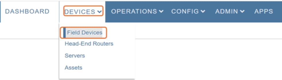
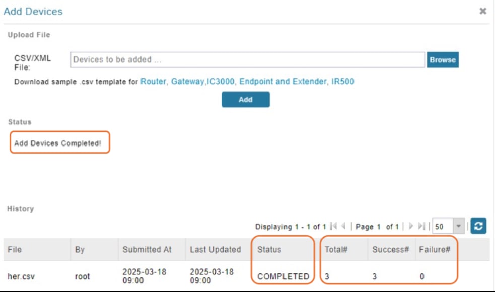
Step 3. Choose Inventory, and click Add Devices.
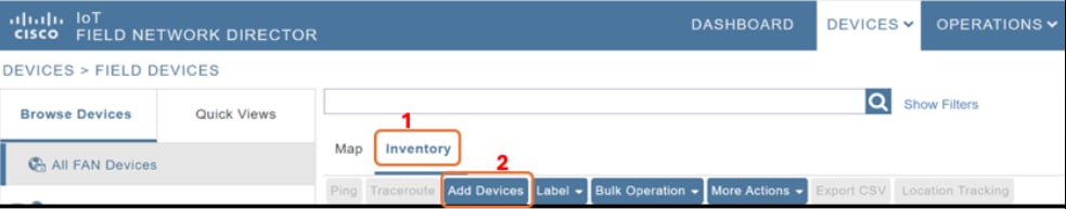
Step 4. In the CSV/XML file field, click Browse and then Add to upload the CSV file you created.
When the upload is complete, in the Add Devices page, the History table displays the status of the file upload as Completed. The table entry also displays the total number of routers in the CSV, and the number of successful and failed uploads.

Configure Cisco IoT FND provisioning settings
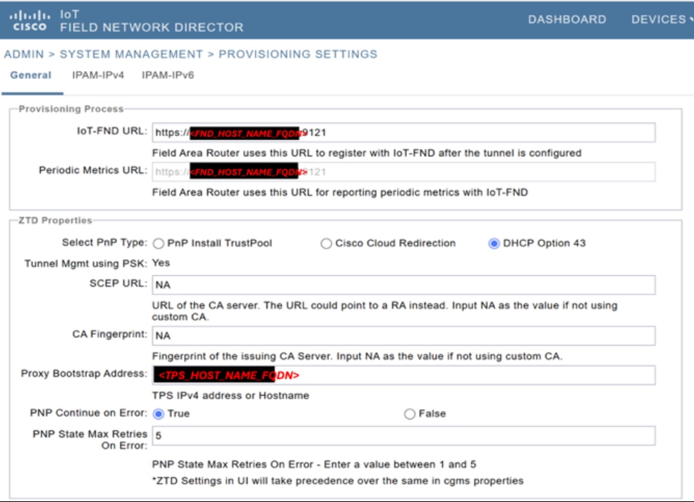
Step 1. In the Cisco IoT FND GUI, from the menu, choose Admin > System Management > Provisioning Settings.
Step 2. In the General tab:
i. In the IoT-FND URL field, enter https://<FND_HOST_NAME_FQDN>:9121.
ii. In the Select PnP Type field, select DHCP Option 43.
iii. In the SCEP URL field, enter NA.
iv. In the CA Fingerprint field, enter NA.
v. In the Proxy Bootstrap Address field, the TPS_HOST_NAME_FQDN value is displayed by default.
vi. In the PNP Continue on Error field, select True.
vii. In the PNP State Max Retries On Error field, enter 5.
Step 3. Configure IPAM subnets to help Cisco IoT FND dynamically allocate IP address to the loopback interface of field routers. In the IPAM-IPv4 tab:
i. Enter the subnet address
ii. Enter the exclusion range of IP addresses within a subnet to exclude from being assigned to devices
iii. Click the disk icon to save the settings
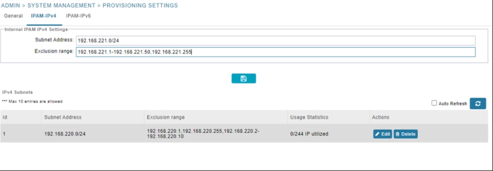
Step 4. A list of porbable IP addresses that may be generated is displayed. Click Yes to initiate IP address generation.
Step 5. (Optional) In the IPAM-IPv6 tab;
i. Enter the subnet address
ii. Enter the exclusion range of IP addresses within a subnet to exclude from being assigned to devices
iii. Click the disk icon to save the settings
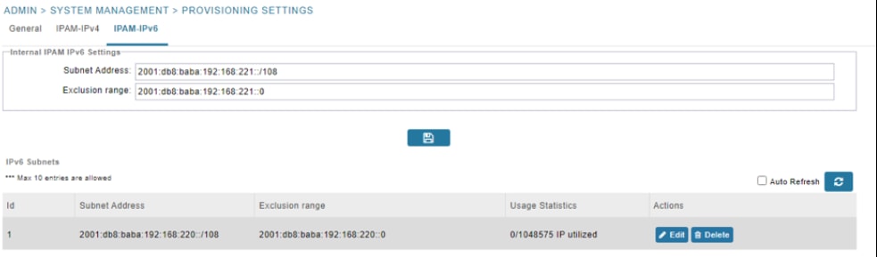
Step 6. A list of porbable IP addresses that may be generated is displayed. Click Yes to initiate IP address generation.
Following the steps outlined above, the addition of HER and field devices is complete. The necessary settings for Plug and Play (PnP) and Zero Touch Deployment (ZTD), as well as the addition of subnets for IP Address Management (IPAM), have also been configured. The next section contains instructions on initiating PnP and ZTD.
Note: This guide demonstrates PnP bootstrapping using manual PnP profile configuration. For automatic PnP Server discovery methods, see the Cisco Network PnP - Available Discovery Methods section of Distribution Automation-Secondary Substation Design Guide.
To configure PnP and ZTD, you must add the following tunnel provisioning templates to field routers:
● Router Bootstrap configuration template
● Router Tunnel Addition Template
● HER Tunnel Addition Template
● HER Tunnel Deletion Template
Table 10. Configuration items for PnP and ZTP configurations
| Configuration item |
Description |
| NTP_SERVER_1 |
Primary NTP server used for time synchronization. |
| NTP_SERVER_2 |
Backup NTP server used for time synchronization. |
| DOMAIN_NAME |
Domain name used across the network. |
| HER_HOST_NAME |
Hostname of HER, also used as local key-id on HER and remote key-id on field router for PSK-based key rings. |
| FND_HOST_NAME_FQDN |
Hostname of Cisco IoT FND including domain name. |
| FND_CORP_DATA_NETWORK_IP |
IP Address for Cisco IoT FND Corporate Data Network which is used for communication with HER and TPS. |
| TPS_HOST_NAME_FQDN |
Hostname of TPS including domain name. |
| TPS_DMZ_FIELD_ROUTER_FACING _NETWORK _GATEWAY |
Gateway of field-router-facing network. |
| TPS_DMZ_FIELD_ROUTER_FACING_NETWORK_IP |
IP address for TPS field-router-facing network used for communication with field router. |
| IPSEC_TRANSFORM_SET_MODE |
IPSec transform set mode can be either transport or tunnel. Configure it based on the network design. |
| NEXTHOP_IP_TO_REACH_TPS_FROM_FIELD_ROUTER |
Nexthop IP address to reach TPS from field router for PnP. |
| IP_MTU |
Maximum IPv4 MTU supported between field router and DMZ Network through the provider network. See the Appendix section for calculation reference. |
| TCP_MSS |
Maximum IPv4 Segment Size supported between field router and DMZ Network through the provider network. See the Appendix section for calculation reference. |
Add tunnel provisioning templates
Create a tunnel group and add field routers
Step 1. In Cisco IoT FND GUI, from the main menu, choose Config > Tunnel Provisioning.
Step 2. Click the add icon.
Step 3. Enter a group name.
Step 4. Click Add.
Step 5. Select Default-Ir1100.
Step 6. From Group Members drop-down list, choose Router.
Step 7. Select the field router.
Step 8. Click Change Tunnel Group.
Step 9. From the drop-down list, choose the newly added tunnel group and click Change Tunnel Group.
Navigate to the new tunnel group and verify if the field router is present in the Group Members tab.
The router bootstrap template content is also available on Github.
Step 1. In the Router Bootstrap configuration tab, replace the existing template with a custom template.
The following sample template must be edited to add domain names and NTP server configurations. You can uncomment any section by removing the lines [COMMENT-START] and [COMMENT-END]
<#-- This is a sample template can be used for router bootstrapping with minimal configs.
Please go through the template carefully and find the section to uncomment and add Domain name and NTP Server configurations.
NOTE: To uncomment any section, remove the lines containing [COMMENT-START] and [COMMENT-END]
-->
<#if far.isRunningIos()>
<#-- New section to support Day 0 operation -->
<#if isBootstrapping??>
<#assign sublist=far.eid?split("+")[0..1]>
<#assign sn=sublist[1]>
file prompt quiet
do mkdir flash:Archive
!
service timestamps debug datetime msec
no service password-encryption
!
<#-- the following license commands are listed here as those are not config replace friendly and might be automatically added at a later stage. -->
license smart reservation
license smart transport off
no ip http client source-interface ${far.tunnelSrcInterface1}
!
hostname FR${sn}
!
username ${far.adminUsername} privilege 15 algorithm-type sha256 secret ${far.adminPassword}
aaa new-model
aaa authentication login default local
aaa authorization exec default local
!
<#-- [MANDATORY] Uncomment and update Domain Configs given below -->
<#-- [COMMENT-START]
ip domain name <DOMAIN_NAME>
[COMMENT-END] -->
<#-- [MANDATORY] Uncomment and update Static Route to TPS Configs given below -->
<#-- [COMMENT-START]
ip route <TPS_DMZ_FIELD_ROUTER_FACING_NETWORK_IP> 255.255.255.255 ${far.tunnelSrcInterface1}
[COMMENT-END] -->
service timestamps log datetime localtime
!
<#-- [MANDATORY] Uncomment and update NTP Configs given below -->
<#-- [COMMENT-START]
clock timezone IST +5 30
ntp server <NTP_SERVER_1> prefer
ntp server <NTP_SERVER_2>
ip route <NTP_SERVER_1> 255.255.255.255 ${far.tunnelSrcInterface1}
ip route <NTP_SERVER_2> 255.255.255.255 ${far.tunnelSrcInterface1}
[COMMENT-END] -->
!
crypto key generate rsa general-keys label SSH modulus 2048
ip ssh rsa keypair-name SSH
ip ssh version 2
!
<#-- Adjust TCP MSS values as per your network -->
ip tcp mss <TCP_MSS>
!
interface loopback999
description workaround for CSCvb49055
ip address 169.254.1.2 255.255.255.255
!
cgna initiator-profile cg-nms-tunnel
execution-url https://169.254.1.2:443/wsma/config
!
cgna initiator-profile cg-nms-tunnel
callhome-url https://<TPS_HOST_NAME_FQDN>:9120/cgna/ios/config
execution-url https://169.254.1.2:443/wsma/config
post-commands
add-command show hosts | format flash:/managed/odm/cg-nms.odm
add-command show interfaces | format flash:/managed/odm/cg-nms.odm
add-command show version | format flash:/managed/odm/cg-nms.odm
add-command show ipv6 dhcp | format flash:/managed/odm/cg-nms.odm
add-command show ipv6 interface | format flash:/managed/odm/cg-nms.odm
add-command dir flash:/before-tunnel-config | format flash:/managed/odm/cg-nms.odm
interval 10
gzip
!
cgna gzip
no ip http server
ip http authentication aaa login-authentication default
ip http tls-version TLSv1.2
ip http secure-server
ip http timeout-policy idle 600 life 86400 requests 3
ip http client connection timeout 5
ip http client connection retry 5
!
wsma agent exec
profile exec
!
wsma agent config
profile config
!
wsma profile listener exec
transport https path /wsma/exec
!
wsma profile listener config
transport https path /wsma/config
!
event manager directory user policy "flash:/managed/scripts"
event manager policy no_config_replace.tcl type system authorization bypass
!
event manager applet post_pnp
event timer watchdog time 30
action 10.0 cli command "enable"
action 11.0 cli command "show pnp profile | inc Active:0"
action 12.0 regexp "Active:0.*" "$_cli_result" pnpStatus
action 13.0 if $_regexp_result eq 1
action 14.0 cli command "config t"
action 15.0 cli command "no key config-key password-encrypt" pattern ".*"
action 16.0 cli command "yes"
action 17.0 cli command "key config-key password-encrypt ${far.adminPassword}"
action 18.0 cli command "password encryption aes"
action 19.0 cli command "archive"
action 20.0 cli command "path flash:/Archive/"
action 21.0 cli command "maximum 8"
action 22.0 cli command "ip http client secure-trustpoint CISCO_IDEVID_SUDI"
action 25.0 cli command "no event manager applet post_pnp"
action 80.0 cli command "do delete /force flash:express-setup-config"
action 81.0 cli command "do copy running-config flash:express-setup-config"
action 82.0 cli command "no file prompt quiet"
action 89.1 cli command "cgna initiator-profile cg-nms-tunnel"
action 89.2 cli command "active"
action 90.0 end
action 99.0 cli command "end"
</#if>
<#else>
${provisioningFailed("Field Router is not running IOS")}
</#if>
Step 2. Click the disk icon to save the changes.
Add router tunnel addition template
The router tunnel addition template content is also available on Github.
Step 1. In the Router Tunnel Addition tab, replace the existing template with a custom template.
You must edit the following sample template. You can uncomment any section by removing the lines [COMMENT-START] and [COMMENT-END].
<#-- This is a sample template can be used for router tunnel addition with minimal configs.
Please go through the template carefully and find the section to uncomment and update highlighted configurations.
NOTE: To uncomment any section, remove the lines containing [COMMENT-START] and [COMMENT-END]
-->
<#-- This template only supports Field Router’s running IOS. -->
<#if !far.isRunningIos()>
${provisioningFailed("Field Router is not running IOS")}
<#else>
<#--
For Field Routers running IOS configure a FlexVPN client in order to establish secure
communications to the HER. This template expects that the HER has been
appropriately pre-configured as a FlexVPN server.
-->
<#assign sublist=far.eid?split("+")[0..1]>
<#assign sn=sublist[1]>
<#--
Configure a Loopback0 interface for the Field Router.
-->
interface Loopback0
<#--
If the loopback interface IPv4 address property has been set on the Field Router CSV
then configure the interface with that address. Otherwise obtain an
address for the interface using IPAM.
-->
<#if far.loopbackV4Address??>
<#assign loopbackIpv4Address=far.loopbackV4Address>
<#elseif far.isIPAMSelected()??>
<#assign loopbackIpv4Address=far.IPAMIpv4address(1)>
<#else>
${provisioningFailed("Neither loopbackIpv4Address is populated in CSV, nor IPAM is selected")}
</#if>
ip address ${loopbackIpv4Address} 255.255.255.255
exit
!
ip http client source-interface Loopback0
<#--
Configure the Field Router's FQDN.
-->
<#-- [COMMENT-START]
ip host <FND_HOST_NAME_FQDN> <FND_CORP_DATA_NETWORK_IP>
[COMMENT-END]-->
<#--
Default to using FlexVPN for the tunnel configuration of Field Router’s running IOS.
-->
<#if (far.useFlexVPN!"true") = "true">
<#--
Defining ACL to advertise Field Router’s Loopback IPv4 address to HER.
It can also be used to advertise other LAN prefixes connected to Field Router
Example 10.10.10.0 with sequence 20
-->
ip access-list standard FlexVPN_Client_IPv4_LAN
10 permit ${loopbackIpv4Address}
<#-- [COMMENT-START]
20 permit 10.10.10.0
[COMMENT-END]-->
exit
<#--
Advertise IPv4 LAN prefixes to HER using IKEv2 prefix injection
-->
crypto ikev2 authorization policy FlexVPN_Author_Policy
route set access-list FlexVPN_Client_IPv4_LAN
route set interface
exit
!
crypto ikev2 fragmentation mtu 1000
!
crypto ikev2 proposal FlexVPN_IKEv2_Proposal
encryption aes-cbc-256
group 14
integrity sha256
exit
crypto ikev2 policy FLexVPN_IKEv2_Policy
proposal FlexVPN_IKEv2_Proposal
exit
<#-- FlexVPN authorization policy is defined locally. -->
aaa authorization network FlexVPN_Author local
<#-- [COMMENT-START]
crypto ikev2 keyring FlexVPN_Keyring
peer <HER_HOST_NAME>
address ${far.ipsecTunnelDestAddr1}
identity key-id <HER_HOST_NAME>
pre-shared-key ${far.mgmtVpnPsk}
exit
exit
crypto ikev2 profile FlexVPN_IKEv2_Profile
match identity remote key-id <HER_HOST_NAME>
identity local fqdn FR${sn}.<DOMAIN_NAME>
authentication remote pre-share
authentication local pre-share
keyring local FlexVPN_Keyring
dpd 30 3 periodic
aaa authorization group psk list FlexVPN_Author FlexVPN_Author_Policy
exit
<#--
If the headend router is an ASR then use a different configuration for the
transform set as some ASR models are unable to support the set we'd prefer
to use.
-->
<#if her.pid?contains("ASR")>
crypto ipsec transform-set FlexVPN_IPsec_Transform_Set esp-aes esp-sha-hmac
mode <IPSEC_TRANSFORM_SET_MODE>
exit
<#else>
crypto ipsec transform-set FlexVPN_IPsec_Transform_Set esp-aes esp-sha256-hmac
mode <IPSEC_TRANSFORM_SET_MODE>
exit
</#if>
[COMMENT-END]-->
crypto ipsec profile FlexVPN_IPsec_Profile
set ikev2-profile FlexVPN_IKEv2_Profile
set pfs group14
set transform-set FlexVPN_IPsec_Transform_Set
exit
<#assign wanInterface=far.interfaces(far.tunnelSrcInterface1!"Cellular")>
interface Tunnel11
description IPsec tunnel to ${her.eid}
ip unnumbered loopback0
tunnel destination ${far.ipsecTunnelDestAddr1}
tunnel protection ipsec profile FlexVPN_IPsec_Profile
tunnel source ${far.tunnelSrcInterface1}
ip mtu <IP_MTU>
ip tcp adjust-mss <TCP_MSS>
exit
<#if !(far.ipsecTunnelDestAddr1??)>
${provisioningFailed("Field Router property ipsecTunnelDestAddr1 must be set to the address of the HER for FlexVPN tunnel destination")}
</#if>
crypto ikev2 client flexvpn FlexVPN_Client
exit
ip http secure-client-auth
no ip http tls-version TLSv1.2
</#if>
</#if>
Step 2. Click the disk icon to save the changes.
Add HER tunnel addition template
The HER tunnel addition template content is also available on Github.
Step 1. In the HER Tunnel Addition tab, replace the existing template with the following content.
<#-- This template only supports HERs running IOS or IOS XE. -->
<#if !her.isRunningIos() && !her.isRunningIosXe()>
${provisioningFailed("HER is not running IOS or IOS XE")}
</#if>
<#if far.isRunningIos()>
<#assign sublist=far.eid?split("+")[0..1]>
<#assign sn=sublist[1]>
crypto ikev2 keyring FlexVPN_Keyring
peer FR${sn}
identity fqdn FR${sn}.<DOMAIN_NAME>
pre-shared-key ${far.mgmtVpnPsk}
exit
exit
</#if>
Step 2. Click the disk icon to save the changes.
Add HER tunnel deletion template
The HER tunnel deletion template content is also available on Github.
Step 3. In the HER Tunnel Deletion tab, replace the existing template with the following content.
<#-- This template only supports HERs running IOS or IOS XE. -->
<#if !her.isRunningIos() && !her.isRunningIosXe()>
${provisioningFailed("HER is not running IOS or IOS XE")}
</#if>
<#if far.isRunningIos()>
<#assign sublist=far.eid?split("+")[0..1]>
<#assign sn=sublist[1]>
crypto ikev2 keyring FlexVPN_Keyring
no peer FR${sn}
exit
</#if>
Step 4. Click the disk icon to save the changes.
Create field router configuration group
Step 1. In Cisco IoT FND GUI, from the main menu, choose Config > Device Configuration.
Step 2. Click the add icon.
Step 3. Enter a group name and click Add.
Step 4. Select the group Default-Ir1100.
Step 5. In the Group Members tab, from the drop-down list, choose Router.
Step 6. Select the field router.
Step 7. Click Change Configuration Group.
Step 8. From the drop-down list, choose the newly added configuration group
Step 9. Click Change Configuration Group to move the selected field router to the new group.
Navigate to the new configuration group and verify if the field router is present in the Group Members tab.
The device configuration template content is also available on Github.
Step 1. In the Edit Configuration tab, replace the existing template with the following content.
<#if far.isRunningIos()>
<#--
If a Loopback0 interface is present on the device (normally configured
during tunnel provisioning) then use that as the source interface for
the HTTP client and SNMP traps. The source for the HTTP client is not
changed during tunnel provisioning because usually the addresses assigned
to the loopback interface are only accessible through the tunnels.
Waiting ensures the tunnel is configured correctly and comes up.
-->
<#if far.interfaces("Loopback0")?size != 0>
ip http client source-interface Loopback0
snmp-server trap-source Loopback0
</#if>
!
<#-- Enable periodic inventory notification every 1 hour to report metrics. -->
cgna profile cg-nms-periodic
interval 60
exit
</#if>
Step 2. Click the disk icon to save the changes.
Note: If this is a fresh installation and you have not carried out PnP or ZTD for the router, start with Step 3.
Step 1. Access the IR1101 console and delete the before configuration files.
Note: Skip this step if this is a fresh installation and router has not already gone through PnP/ZTD.
Router#dir bootflash:before*
Directory of bootflash:/before*
Directory of bootflash:/
134031 -rw- 11423 Mar 7 2025 20:22:11 +05:30 before-tunnel-config
134032 -rw- 14049 Mar 7 2025 20:23:24 +05:30 before-registration-config
2788687872 bytes total (424030208 bytes free)
Router#delete bootflash:before*
Delete filename [before*]?
Delete bootflash:/before-tunnel-config? [confirm]
Delete bootflash:/before-registration-config? [confirm]
Router#
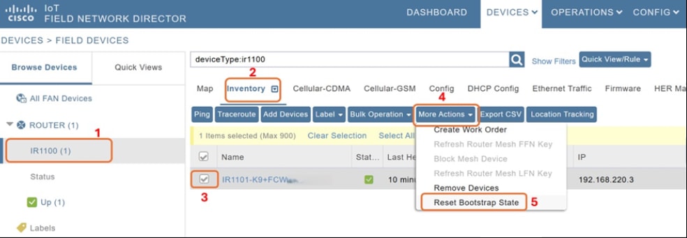
Step 2. The field router must be in unheard state. If the router is not reported as unheard in the Cisco IoT FND GUI, carry out the following steps in the GUI:
Note: Skip this step if this is a fresh installation and router has not already gone through PnP/ZTD.
i. From the main menu choose Devices > Field Devices.
ii. From the Browse Devices menu, from the Router list, choose IR1101.
iii. Click Inventory.
iv. Select the device that you want to bootstrap.
v. From the More Actions drop-down list, choose Reset Bootstrap State to update the device to unheard state.
Step 3. Bringup IR1101 and verify that TPS and HER IP addresses are reachable from the field router over GigabitEthernet or Cellular interface.
Step 4. After reachability is established, enter the following commands in the field router console.
ip host <TPS_HOST_NAME_FQDN> <TPS_DMZ_FIELD_ROUTER_FACING_NETWORK_IP>
pnp profile custom_pnp
transport http host <TPS_HOST_NAME_FQDN> port 9125
!
Step 5. In the Cisco IoT FND GUI, from the main menu, choose Config > Tunnel Provisioning.
Step 6. Select the newly created group and click the Bootstrapping tab to view the events during the bootstrapping process.
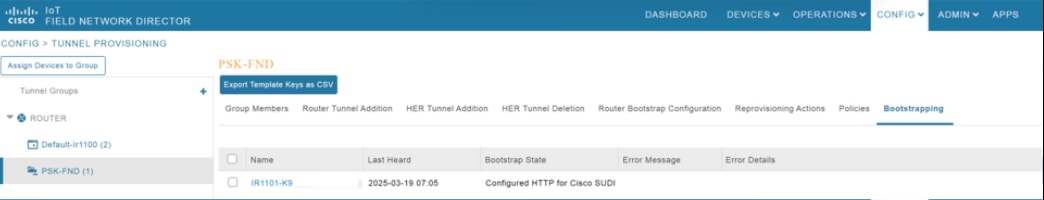
Step 7. Click the EID.
Step 8. In the Events tab, view the overall events at the device level.
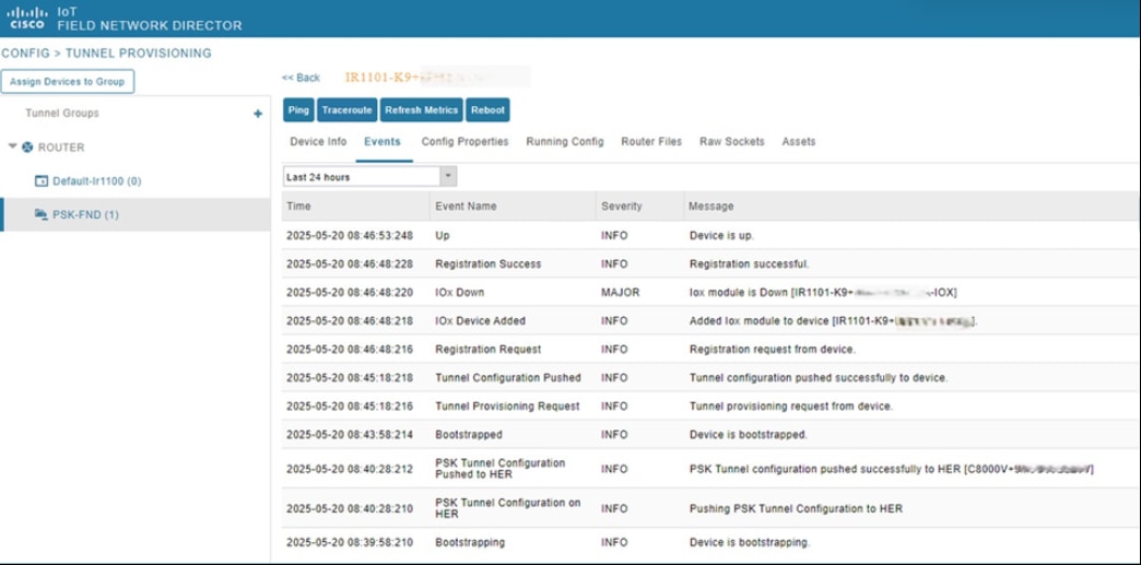
Table 11. Configuration items used in the guide
| Configuration item |
Description |
Value |
| ESXI_HOST_URL |
IP Address of the ESXi host (version 6.5 and above) where the Cisco IoT FND VM will be deployed. |
|
| ESXI_HOST_USERNAME |
Username to access the ESXi host. |
|
| ESXI_HOST_PASSWORD |
Password to access the ESXi host. |
|
| FND_OVA_IMAGE |
Cisco IoT FND OVA Image |
|
| TPS_OVA_IMAGE |
TPS OVA Image |
|
| ADMIN_NETWORK_PORTGROUP |
ESXi Port group that will be used for Admin Network for SSH and GUI access. |
|
| CORP_DATA_NETWORK_PORTGROUP |
ESXi Port group that will be used for Corporate Data Network for the communication of Cisco IoT FND with HER, TPS and Field Router(via TPS or HER) |
|
| DMZ_FIELD_ROUTER_FACING_NETWORK_PORTGROUP |
ESXi Port group that will be used for communication with Field Router over DMZ |
|
| ADMIN_NETWORK_NMCLI_CONNECTION_NAME |
Admin Network Connection name ; Keep it same as device-name for simplicity. Ex: eth0, ens192 etc., |
|
| CORP_DATA_NETWORK_NMCLI_CONNECTION_NAME |
Corporate Network Connection name ; Keep it same as device-name for simplicity. Ex: eth0, ens192 etc., |
|
| DMZ_FIELD_ROUTER_FACING_NETWORK_NMCLI_CONNECTION_NAME |
DMZ Field Router Facing Network Connection Name; Keep it same as device-name for simplicity. Ex: eth0, ens192 etc., |
|
| NTP_SERVER_1 |
Primary NTP server used for Time synchronization |
|
| NTP_SERVER_2 |
Backup NTP server used for Time synchronization |
|
| DOMAIN_NAME |
Domain name used across the Network |
|
| FND_ADMIN_NETWORK_IP |
IP Address for Cisco IoT FND Admin Network which is used for SSH and GUI access |
|
| FND_NMCLI_CONNECTION_NAME_TO_REACH_NTP |
Network Connection name to reach NTP; Could be one of <ADMIN_NETWORK_NMCLI_CONNECTION_NAME> or <CORP_DATA_NETWORK_NMCLI_CONNECTION_NAME> |
|
| FND_CORP_DATA_NETWORK_IP |
IP Address for Cisco IoT FND Corporate Data Network which is used for communication with HER and TPS |
|
| FND_HOST_NAME_FQDN |
Hostname of Cisco IoT FND including domain |
|
| NEXTHOP_TO_REACH_NTP_FROM_FND |
Nexthop IP address to reach NTP from Cisco IoT FND |
|
| FND_CGMS_KEYSTORE |
cgms_keystore to be used for Cisco IoT FND |
|
| FND_KEYSTORE_PASSWORD |
Password of Cisco IoT FND CGMS Keystore |
|
| FND_GUI_URL |
URL to Access Cisco IoT FND |
|
| TPS_HOST_NAME_FQDN |
Hostname of TPS including domain name |
|
| TPS_ADMIN_NETWORK_IP |
IP Address for TPS Admin Network which is used for SSH and GUI access |
|
| TPS_CGMS_KEYSTORE |
TPS CGMS Keystore File |
|
| TPS_NMCLI_CONNECTION_NAME_TO_REACH_NTP |
Network Connection name to reach NTP; Could be one of <ADMIN_NETWORK_NMCLI_CONNECTION_NAME> or <CORP_DATA_NETWORK_NMCLI_CONNECTION_NAME> |
|
| TPS_CORP_DATA_NETWORK_IP |
IP Address for TPS Data Network which is used to communicate over Corporate Data Network with Cisco IoT FND. |
|
| TPS_DMZ_FIELD_ROUTER_FACING _NETWORK _GATEWAY |
Gateway of Field Router Facing Network in TPS |
|
| TPS_DMZ_FIELD_ROUTER_FACING_NETWORK _IP |
IP Address for TPS Field Router Facing Network used for communication with Field Router |
|
| TPS_KEYSTORE_PASSWORD |
Password Protecting Keystore in TPS |
|
| HER_ADMIN_NETWORK_IP |
IP Address for HER Admin Network which is used for SSH and GUI access |
|
| HER_CORP_DATA_NETWORK_IP |
IP Address for HER Corporate Data Network which is used for communication with Cisco IoT FND |
|
| HER_DMZ_FIELD_ROUTER_FACING_NETWORK _GATEWAY |
Nexthop IP address on HER in DMZ Field Router facing network |
|
| HER_DMZ_FIELD_ROUTER_FACING_NETWORK _IP |
IP Address for HER Field router Facing Network used for communication with Field router |
|
| HER_HOST_NAME |
Hostname of HER |
|
| HER_LOOPBACK_IP |
IP Address of HER’s Loopback Interface |
|
| HER_PASSWORD |
Password for accessing HER |
|
| HER_USERNAME |
Username for accessing HER |
|
| NEXTHOP_TO_REACH_NTP_FROM_HER |
Nexthop IP to reach NTP from HER |
|
| IPSEC_TRANSFORM_SET_MODE |
IPSec Transform-set mode can be either transport or tunnel. Configure it based on the network design. |
|
| IP_MTU |
Maximum IPv4 MTU supported between Field-Router to DMZ Network through the Provider network. Refer Appendix 7.4 for steps on calculation if required. |
|
| TCP_MSS |
Maximum IPv4 Segment Size supported between Field-Router to DMZ Network through the Provider network. Refer Appendix 7.5 for steps on calculation if required. |
|
| FIELD_ROUTER_PASSWORD |
Password for accessing Field Router |
|
| FIELD_ROUTER_SERIAL_NUMBER |
Serial Number of Field Router |
|
| FIELD_ROUTER_TUNNEL_SOURCE_INTERFACE |
Source Interface of Tunnel from Field Router to HER |
|
| FIELD_ROUTER_USERNAME |
Username of Field Router |
|
| FIELD_ROUTER_V4_LOOPBACK_IP |
[OPTIONAL] Loopback IP intended to be used for Field Router (If IPAM Feature is not used) |
|
| Acronym |
Definition |
| FND |
Field Network Director |
| HER |
Head-End Router |
| PSK |
Pre-Shared Key |
| IPAM |
IP Address Management |
| TPS |
Tunnel Provisioning Server |
| PnP |
Plug and Play |
| ZTD |
Zero Touch Deployment |
| DHCP |
Dynamic Host Configuration Protocol |
| IPSec |
Internet Protocol Security |
| OVA |
Open Virtual Appliance |
| GUI |
Graphical User Interface |
| SSH |
Secure Shell |
| VM |
Virtual Machine |
| OVF |
Open Virtualization Format |
| NTP |
Network Time Protocol |
| NIC |
Network Interface Card |
| FQDN |
Fully Qualified Domain Name |
| CGMS |
Connected Grid Management System (Old name of CISCO IOT FND) |
| URL |
Uniform Resource Locator |
| CORP |
Corporate |
| DSO |
Distribution System Operator |
| NTP_SERVER_1 |
Primary NTP server used for Time synchronization |
● Distribution Automation-Secondary Substation Design Guide
● Cisco IoT FND 5.0 Release Notes
● Tunnel management with PSK and IPAM
● Cisco IoT FND 5.0 User Guide
● Achieve Scale Beyond 25,000 Routers
Identify Maximum IPv4 MTU supported by network provider using sweep ping
Note: Carry out this task only after you configure <HER_DMZ_FIELD_ROUTER_FACING_NETWORK_IP> and <TPS_DMZ_FIELD_ROUTER_FACING_NETWORK_IP>.
Step 1. Access the console of any field router
Step 2. Enter the ping command.
Step 3. When prompted, enter the target IP address <HER_DMZ_FIELD_ROUTER_FACING_NETWORK_IP>.
Step 4. Choose to use extended commands.
Step 5. Specify the minimum and maximum packet sizes to test the MTU range (For example, minimum size 1401 and maximum size 1600).
Step 6. Set the sweep interval (usually 1-byte increments).
Step 7. Send the sweep ping and observe the results.
| Response |
Definition |
| ! |
Packet traversed to the destination successfully |
| . |
Network could not deliver the packet of that size |
Step 8. Identify the largest packet size that consistently succeeds without loss. This size approximates the MTU supported by the network provider path.
Step 9. Optionally, narrow the sweep range around the size where failures begin to pinpoint the exact MTU.
Router#ping
Protocol [ip]:
Target IP address: <HER_DMZ_FIELD_ROUTER_FACING_NETWORK_IP>
Repeat count [5]: 1
Datagram size [100]:
Timeout in seconds [2]:
Extended commands [n]: y
Ingress ping [n]:
Source address or interface:
DSCP Value [0]:
Type of service [0]:
Set DF bit in IP header? [no]:
Validate reply data? [no]:
Data pattern [0x0000ABCD]:
Loose, Strict, Record, Timestamp, Verbose[none]:
Sweep range of sizes [n]: y
Sweep min size [36]: 1491
Sweep max size [18024]: 1510
Sweep interval [1]:
Type escape sequence to abort.
Sending 20, [1491..1510]-byte ICMP Echos to <HER_DMZ_FIELD_ROUTER_FACING_NETWORK_IP>, timeout is 2 seconds:
!!!!!!!!!!......!...
Success rate is 55 percent (11/20), round-trip min/avg/max = 52/85/124 ms
As you see in above example, Ping is consistently working till packet size of 1500 and is inconsistent above that size. This could vary from network to network, choose the value according to your network.
Note: Repeat this task for <TPS_DMZ_FIELD_ROUTER_FACING_NETWORK_IP> as well.
Identify the Maximum TCP Maximum Segment Size (MSS) supported by Network Provider
To calculate the TCP MSS, use the formula:
TCP MSS = MTU – (IP Headers + TCP Header size)
The standard header sizes are:
● IP header: 20 bytes
● TCP header: 20 bytes
So, for a standard configuration: TCP MSS = MTU – 40 bytes
Note: Some networks may include additional headers such as VLAN tags, GRE, or IPsec encapsulations that increase the total header size. In such cases, adjust the MSS calculation to account for the additional overhead specific to your network setup.