Distribution Automation Design Guide, 3.1
Available Languages
Bias-Free Language
The documentation set for this product strives to use bias-free language. For the purposes of this documentation set, bias-free is defined as language that does not imply discrimination based on age, disability, gender, racial identity, ethnic identity, sexual orientation, socioeconomic status, and intersectionality. Exceptions may be present in the documentation due to language that is hardcoded in the user interfaces of the product software, language used based on RFP documentation, or language that is used by a referenced third-party product. Learn more about how Cisco is using Inclusive Language.
- US/Canada 800-553-2447
- Worldwide Support Phone Numbers
- All Tools
 Feedback
 Feedback
Distribution Automation Architecture for Utilities
Distribution Automation Use Cases
Direct Transfer Trip over Cellular
Secondary Substation Monitoring and Control
Secondary Substation Router Functions
Volt/VAR Control Use Case and Benefits
Fault, Location, Isolation, Service Restoration (FLISR)
Distribution Automation – ICT Design Options
Centralized NMS with Regional SCADA Control Centers
Scalable IKEv2 CLB Cluster Design for the Headend
Dual Data Center Design Using BGP Route Advertisement
BGP Autonomous System (AS) Assignments
Recommended Topology: Active/Active
Deployment Topology Components
Distribution Automation Solution Architecture
Peer-to-Peer Layer 2 Communication over Layer 3 Networks
Locally-Switched IED Communication
Hub-Switched IED Communication
Tunnel Provisioning Server (TPS)
RSA Certificate Authority (CA)
Network Time Protocol (NTP) Server
SSR, DA, and DER Gateways: Cisco Catalyst IR1101
Expansion Module for IR1101 Industrial Integrated Services Router
SCADA and other IED simulations
Summary of IP Address Allocation Methods
SCADA Components and Protocols
Raw Socket Dual Control Center Multi-Drop Bridging
Upstream QoS: from IED to SCADA
Downstream QoS (from SCADA to IED):
Zero Touch Onboarding of Cisco IOS-XE Routers
Cisco Network Plug and Play (PnP)
PnP Server Discovery Through DHCP Server
PNP Server Discovery Through DNS Server
PnP Server Discovery Through Cisco PnP Connect
Manual PnP Profile Configuration
Bootstrapping and Deployment Options
Actors Involved in PnP and Their Roles
Roles of PnP Actors in each PnP Server Discovery Method—Summary Matrix
Certificate Considerations for PnP and ZTD
Considerations for Cellular Backhaul (Private APN vs. Public APN)
Network Management System (NMS)
Bootstrapping and Zero Touch Deployment
Facilitating Controller Device Upgrades
IoT Gateway Edge Compute Application Lifecycle Management
Security, High Availability, and Scale
Security Management in the Secondary Substation
Authentication, Authorization, and Accounting (AAA)
Certificate-Based Authentication
Dual LTE WAN Redundancy Scenarios
Active/Standby-Shut Scenario: Operational State
Active/Standby-Shut Scenario: Failover State
Active/Standby-Shut Scenario: Recovery State
Active/Standby-Shut Scenario: Resiliency Life Cycle
Active/Active Load-Sharing Scenario
Appendix A: Related Documentation
This document offers a complete guide to Cisco's Smart Grid Field Area Network (FAN) solution architecture. It covers various ways this solution can be used, including:
● Monitoring secondary substations for scenarios like Fault Location, Isolation, and Service Restoration (FLISR) and Volt/VAR control.
● Other distribution automation applications such as Direct Transfer Trip.
The guide also provides details on the system's overall structure, different ways it can be deployed, specific deployment instructions, recommended best practices, and potential challenges you might face during implementation.
The Distribution Automation solution helps optimize the electricity distribution grid, driven by important business goals. By establishing a widespread, highly available, and well-designed communication network, utilities can achieve:
● Increased network reliability and uptime.
● Reduced operational expenses (OpEx).
Cisco Systems is actively addressing the networking needs of the utility industry. This guide highlights communication solutions for the utility distribution grid, supporting use cases like:
● Supervisory Control and Data Acquisition (SCADA) control transport.
● FLISR.
● Line voltage monitoring.
These solutions enable advanced applications such as:
● Volt/VAR control (managing voltage and reactive power).
● Direct Transfer Trip between substations, feeder sites, and distributed energy resource (DER) sites.
Additionally, monitoring field devices like transformers can help predict maintenance needs, preventing customer outages and costly, unplanned repairs or truck dispatches.
As part of Cisco’s leading, validated, and secure networking solutions for substation automation, Utility Wide Area Networks (WAN), and FAN Advanced Metering Infrastructure (FAN AMI), the Cisco Distribution Automation validated solution offers these unique capabilities for distributed control and protection operations:
● Cost-Effective and Scalable Connectivity: Combines cellular networking with FlexVPN technologies to connect a growing number of Distribution Automation devices across the grid efficiently.
● Robust Security: Features an IT-preferred security architecture, including hardware and software certification management, firewalls, malware protection, and strong encryption for secure network communications and edge applications.
● Enhanced Management: Utilizes Cisco Field Network Director (FND) for improved management and serviceability, featuring Zero Touch Deployment (ZTD) and plug-and-play (PnP) functionality for easier setup and operations.
● High Availability: Designed with redundancy in the headend and WAN, supporting redundant control centers.
● Edge Application Capabilities: Allows deployment, monitoring, upgrading, and troubleshooting of applications on Cisco equipment managed through FND.
● Validated Solutions: End-to-end testing and validation have been completed and documented with various Distribution Automation device vendors and use cases.
Cellular technology is ideal for areas or situations requiring extremely high performance. Since it's all managed under a single, user-friendly Field Network Director (FND) system, customers experience consistent and intuitive management.
This Distribution Automation (DA) architecture is a fundamental part of any Cisco network, providing enhanced, end-to-end security from the control center all the way to the edge of the distribution network. It also secures the final connection between Cisco gateways and utility controller devices using MACsec. The result is a reliable, scalable, and highly available DA network using wired, wireless, and cellular WAN technologies. This network supports large-scale DA deployments and ensures secure communications to redundant control centers.
Deployment and operations are simplified using industry-standard protocols, Plug and Play bootstrapping, and Zero Touch Deployment tools, all proven for large-scale DA rollouts.
This design guide specifically details the DA communications solution using the Cisco IR1101 as the cellular gateway and Cisco IoT FND as the network management system.
Distribution Automation Architecture for Utilities
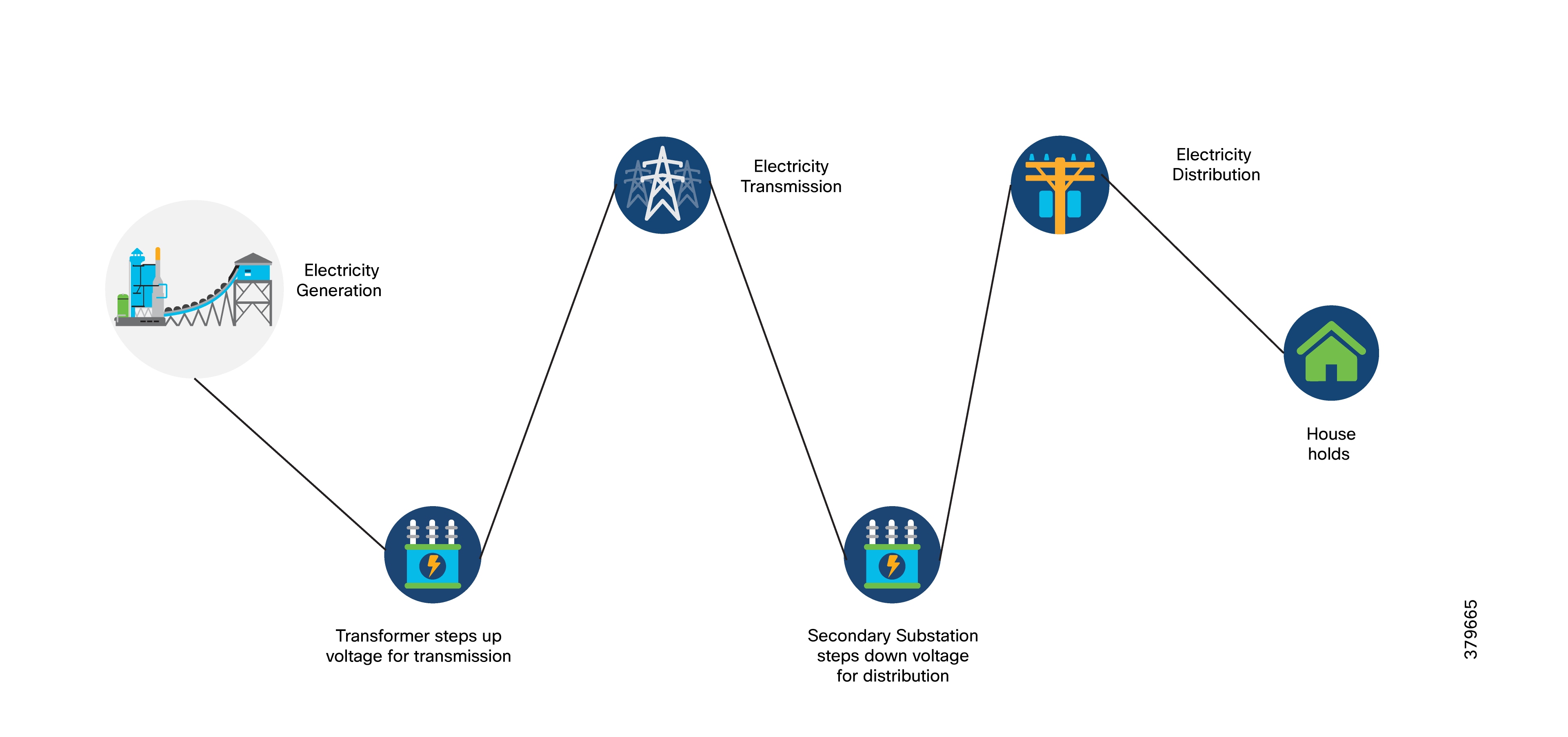
The primary goal of Distribution Automation in the utility grid is to automatically adjust to changes in load, distributed power generation, and fault conditions within the grid often without human intervention. This requires controlling field devices, meaning that the information technology (IT) infrastructure must be advanced enough to support automated decision-making in the field and reliably relay critical information to the Utility Control Center.
The IT infrastructure needs to support real-time data collection and communication with utility databases and other automated systems. Accurate modeling of distribution operations helps ensure optimal decision-making both at the control center and in the field. This heavily relies on a highly reliable and high-performing communications infrastructure, which this document addresses as a core architecture, covering the key use cases below.
Distribution Automation technologies are now widely available for large-scale utility deployments. The key for utilities is to identify and unlock the value these solutions provide. Applications with the greatest potential often directly impact operations and efficiency, such as:
● Managing peak loads through demand response.
● Using predictive technologies for advanced maintenance or equipment replacement.
● Ensuring secure communications for equipment and system restoration technologies.
Automated control of devices in distribution systems involves a closed-loop control of switching devices, voltage controllers, and capacitors based on recommendations from distribution optimization algorithms. These closed-loop systems often have strict communication system requirements that vary by manufacturer and application. The communication system must meet the most demanding standards and operate effectively at scale.
There are two main applications or use cases for optimizing the distribution grid for utilities:
● Volt/VAR control
● FLISR.
A utility fault (like a short circuit between two phase lines) can affect many customers. The fault must be identified and isolated from the larger utility network. This is done by placing reclosers in the network, which are connected to recloser controllers. The recloser controller acts as a connected gateway, establishing a link to the control center.
When a fault is detected, the reclosers automatically trip (open) to isolate the fault from the rest of the network. This tripping can be automated or initiated from the control center. Once the fault is cleared, the circuit can be closed from the control center. This process is commonly known as FLISR.
This Distribution Automation architecture supports utility requirements for Volt/VAR and FLISR through a robust communications infrastructure that addresses two primary distribution automation schemes:
● Secondary Substation Model: Common in Europe, parts of South America, and Asia, where the distribution scheme uses a more centralized transformer design.
● Feeder Network Model: Prevalent in North America, parts of South America, and along the Pacific Rim, based on a decentralized transformer model.
The reference architecture presented in this section leverages the latest technologies and enhancements to best address these use cases and topologies, using various cellular-based gateways for Secondary Substations, DA sites along feeder lines, and at the network edge.
This architecture covers the requirements for these edge services and communications, the backhaul (WAN), and the Operations and Control Centers (referred to as the Headend).
The Headend aggregates and secures communications for and between distribution automation applications, typically located at the Utility Control Center. This architecture uses secure WAN aggregation for scalability, as feeder sections can involve hundreds or more devices, and the DA network can scale to thousands of feeder segments and Secondary Substation networks with over 100,000 nodes.
Within this architecture, the WAN segment is categorized into two modes:
● On-Net: A high-speed communication network owned and operated by the utility itself. Common examples include SDH/SONET, Carrier Ethernet, or MPLS.
● Off-Net: A network leveraged from a service provider. While it can use the same technologies, it's a shared service that often includes pre-negotiated service level agreements.
For DA networks, the WAN segment often uses a cellular backhaul connection because building a private network in numerous and remote locations, especially in the Secondary Substation model, is frequently too expensive. The NAN (Neighborhood Area Network) Mesh offers opportunities to use the On-Net network as backhaul when the radio network gateway can also be placed at a utility-owned facility, such as a substation or depot.
The edge or NAN is built around a small gateway device or NAN router connected to an edge device, such as a Capacitor Bank Controller (CBC) or a voltage line monitor, depending on the application or service. The connection to the edge device is often serial but is quickly moving towards Ethernet. The NAN router can be configured to provide edge services like:
● Adapting serial connections via raw socket encapsulation.
● Translating serial protocols (e.g., IEC-101) to packet-based protocols (e.g., IEC-104).
The NAN router also provides security services such as 802.1x port-based authentication, encryption, and routing, with potential alternate backhaul options. This ensures a secure connection from the edge device to the control center. For Secondary Substations, the backhaul is most often cellular, with some satellite or DSL options available.
Cisco Resilient Mesh is the latest version of the 900 Mhz Connected Grid Mesh radio with significant performance improvements is gaining adoption in Distribution Automation applications and use cases.
However, Resilient Mesh may not be applicable for all use cases.
The Distribution Feeder network will likely be a combination of mesh and cellular based on hop count, application performance, or latency requirements.
Distribution Automation Use Cases
This design guide discusses these Distribution Automation use cases for the EMEA (Europe, Middle East, and Africa) region:
● Direct Transfer Trip over Cellular
● Secondary Substation Monitoring and Control
● Volt/VAR Control
● FLISR
Distribution Automation involves monitoring and controlling devices on distribution feeders (like line reclosers, load break switches, sectionalizers, capacitor banks, and line regulators) and devices within the distribution substation. DA is an overlay network deployed alongside the distribution feeder. It enables two-way communication between controllers on the feeder and intelligent applications located in the Utility Control Center or Secondary Substation, improving grid reliability, availability, and control.
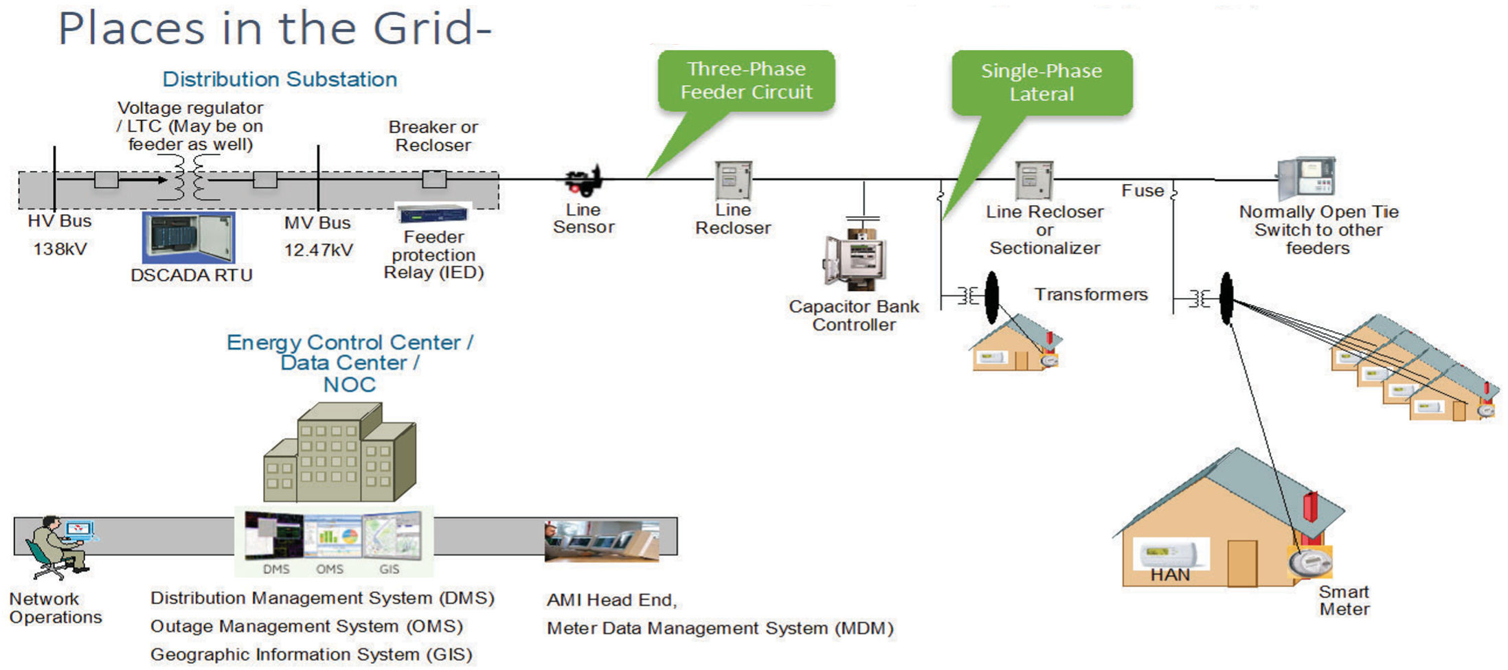
In Europe, feeders are mostly three-phase, and most European countries have a standard secondary voltage of 220, 230, or 240 V.
In Figure 2, you can see the distribution feeder extending from the Secondary Substation. DA controllers (also known as Intelligent Electronic Devices (IEDs)) such as recloser controllers, voltage regulator controllers, and capacitor bank controllers, are positioned along the distribution feeder. Key functions and operations of Distribution Automation include:
● Protecting the distribution system.
● Managing faults.
● Measuring energy usage.
● Managing assets.
● Controlling and managing system performance.
The radial feeder distribution system design is considered for Volt/VAR regulation use cases, while the parallel feeder distribution system is considered for FLISR use cases. Cisco DA Gateways are also well-suited for other feeder deployments, such as mesh and loop distributed feeder designs.
Direct Transfer Trip over Cellular
Traditionally, Direct Transfer Trip Signals (DTT) were sent between substations and remote Distributed Generation (DG) sites using leased telephone lines. DTT systems are typically installed for critical, high-speed tripping of circuit breakers on either side of a feeder connecting substations or between a substation breaker and a DG site’s equipment.
To simplify deployment and offer more flexibility for utility customers, Cisco has developed and validated key use cases using cellular backhaul technology. This approach provides an easy-to-deploy connectivity solution for various distribution grid scenarios, especially for connecting Distributed Energy Resources (DER) assets and local distribution substations.
Advantages of cellular backhaul:
● Availability: Easier to deploy compared to fiber optic cables.
● Reliability: Modern cellular networks offer dependable connectivity.
● Cost-Effectiveness: Cellular solutions are less expensive and faster to implement than dedicated fiber.
● Flexibility: Supports both commercial and private spectrum bands.
The Cisco Catalyst IR1101 is widely used in distribution automation communication networks. The router features modular plug-in cellular modules, allowing it to adapt easily to changing network needs. It supports various commercial and private spectrum bands, making it suitable for diverse deployment environments.
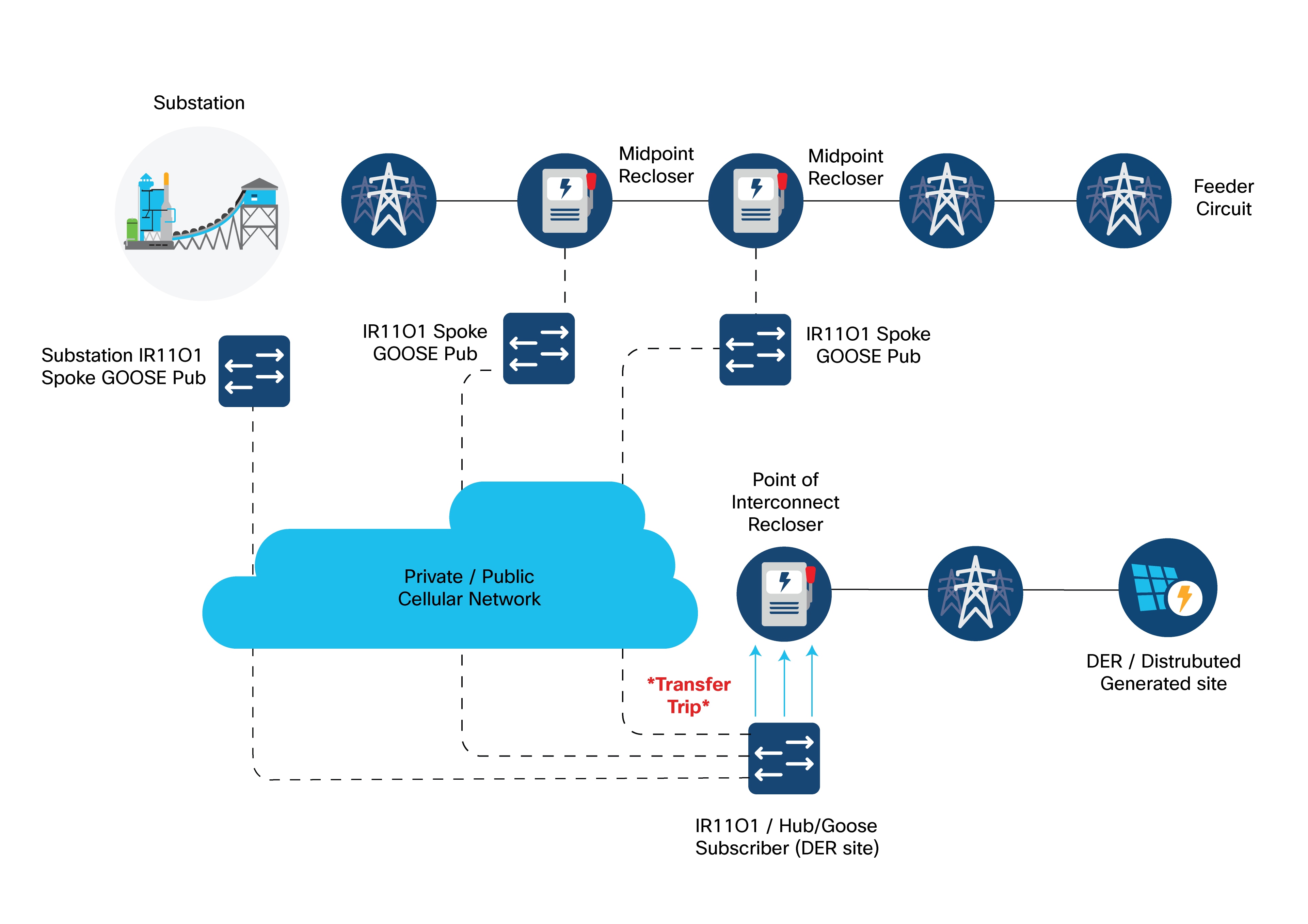
Refer to Distribution Automation Direct Transfer Trip over Cellular for more details on:
● The Engineering Access use case for remote management of grid devices.
● Last mile security using MACSEC.
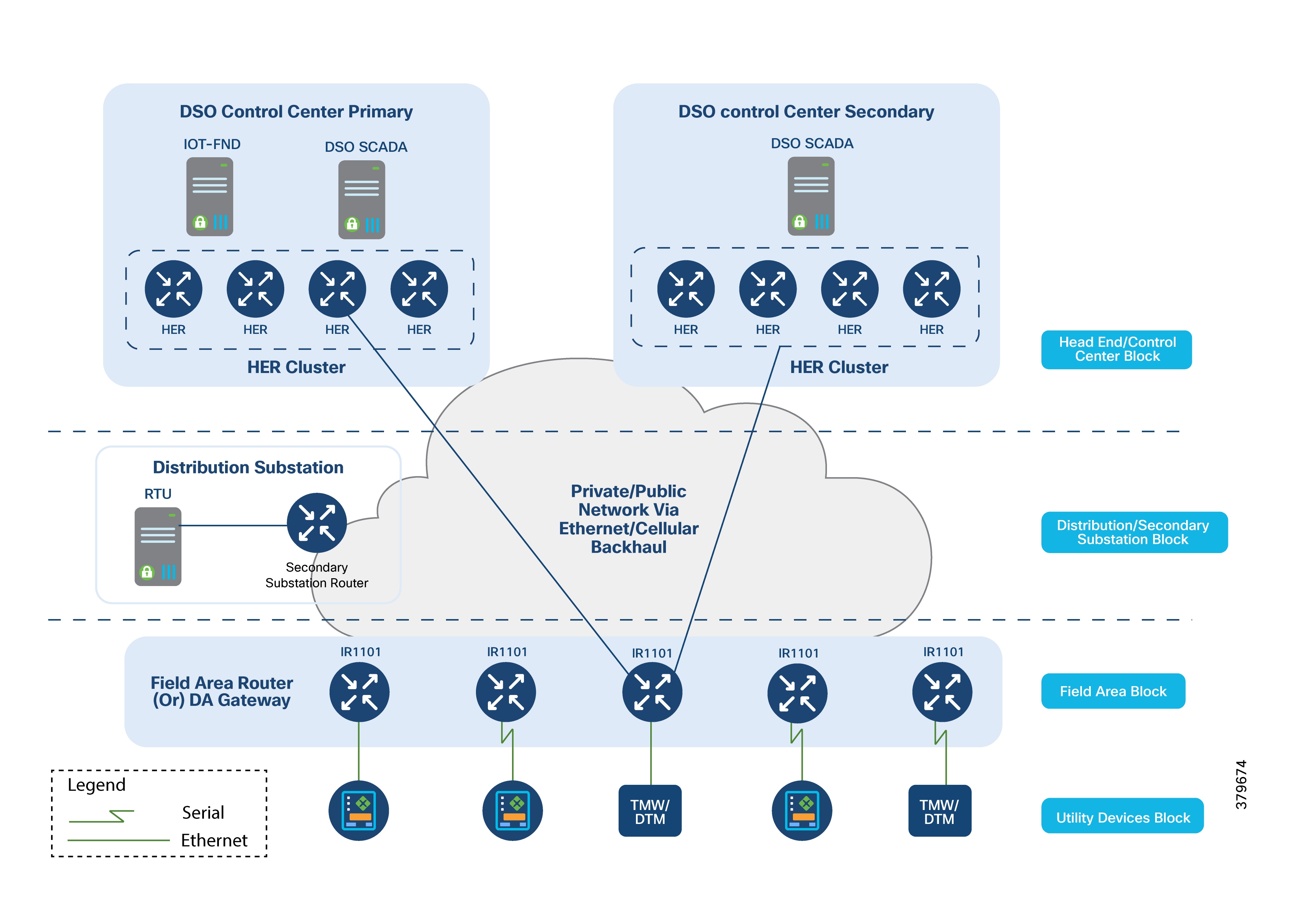
Secondary Substation Monitoring and Control
Secondary Substations reduce power voltage from medium to low for end consumers. They typically have a bus topology, allowing power to be split in multiple directions. Secondary Substations house transformers and various IEDs such as circuit breakers, voltage sensors, reclosers, surge protectors, and gateways (also referred to as Secondary Substation Routers (SSRs)).
The main function of the SSR is to provide reliable, two-way, real-time communication between the IEDs and Remote Terminal Unit (RTU) devices located in the Secondary Substation and the backend SCADA systems running in the Distribution System Operator's (DSO) centralized control center.
Central SCADA applications perform various operational functions on Secondary Substation IEDs and RTUs, including:
● Monitoring: SCADA applications periodically check the voltage and current levels of MV (medium voltage) and LV (low voltage) transformers. This monitoring data is crucial for control, protection, and preventive maintenance. IEDs can be configured to send unsolicited reports to SCADA systems if certain threshold values are exceeded or if a failure occurs.
● Control: Includes remote operations such as opening or closing circuit breakers and switches.
● Protection: Performs various protection functions to isolate the Secondary Substation from the transmission grid in case of a failure.
The following figure illustrates various Secondary Substation components, such as RTUs, IEDs, SSR, and meter data concentrators.
Secondary Substation Router Functions
The Secondary Substation Router (SSR) collects traffic from various IEDs and RTUs and routes it to both primary and secondary regional control centers hosted by the DSO. This is done via public connectivity options like cellular (LTE) or leased lines (Ethernet/Fiber) over an IPv4 or IPv6 backhaul.
The SSR then encrypts application traffic using an IPSec tunnel to maintain data confidentiality over the public network.
The HER in the DSO Control Center aggregates multiple secured tunnels from various SSRs and decrypts the traffic. After decryption, the traffic is routed to the appropriate SCADA application.
RTUs with the older RS232/RS485 interfaces can be directly connected to SSR serial interfaces. Raw sockets or protocol translation techniques are used to transport older application traffic (such as T101) to the control center.
IPv4 IEDs can be directly connected to the SSR's Ethernet port. The SSR can:
● Act as a Dynamic Host Configuration Protocol (DHCP) relay agent to provide IP addresses to IEDs (if they support DHCP client functionality).
● Act as a dot1x relay agent for device-level authentication (if IEDs support the dot1x supplicant feature). If a modern IED supports IPv6 addressing.
● Route IPv6 traffic to IPv6 SCADA applications in the control center.
● Aggregate and route meter concentrator data to a metering application in the DSO Control Center.
● Transport IP camera traffic and asset monitoring traffic to DSO Control Center applications.
For advanced use cases like Distributed Energy Resources (DER), a fiber connection can extend from the Secondary Substation to connect to various IEDs located at customer premises. This is called the extended LAN interface.
Refer to the Design Considerations section for more details on:
● Uplink WAN connectivity, routing, backhaul redundancy, Quality of Service (QoS), encryption, and Network Address Translation (NAT) features performed on the SSR.
● Raw sockets and protocol translation techniques.
● How the SSR can be deployed securely with Zero Touch Deployment over a public internet connection.
● How different configuration profiles for various use cases can be pushed to the SSR.
Volt/VAR Control Use Case and Benefits
This use case focuses on automating the dynamic and efficient delivery of power. Utilities providers aim to achieve significant savings by improving the efficiency of their power distribution infrastructure, which means enhancing the effectiveness of electricity flow. To understand this process, it's important to distinguish between real power and reactive power:
● Real Power: This is the power that performs actual work, used to run lights, devices, and production lines.
● Reactive Power: This power doesn't contribute to doing work but causes conductors to heat up and occupies space in the wires.
The more reactive power flowing on a line, the less room there is for real power, making the distribution system less efficient.
Currently, to eliminate or minimize reactive power flows, utilities deploy devices like capacitor banks or special transformers at substations or on the feeder. These devices work to reduce reactive power flows, making the full capacity of the conductor available for real power. This process is known as Volt/VAR regulation or control:
● Power Factor Regulation/VAR Compensation: Improves the efficiency of energy supply by ensuring voltage and current are in sync when delivered to the customer.
● Conservation Voltage Regulation: During peak load times, ensures that the minimum required voltage level is supplied to the customer.
● Volt/VAR Control: A combination of Power Factor Regulation and Conservation Voltage Regulation.
The following figure shows the various components of the Volt/VAR use case, including Load Tap Changers, Voltage Regulators, and Capacitor Bank Controllers (CBCs).
Voltage Regulator and Load Tap Controllers
Voltage regulation functions are performed by Voltage Regulators or Load Tap Controllers. Voltage is increased or decreased based on load conditions. Voltage regulators are a type of transformer that make small adjustments to voltage levels in response to changes in load.
The regulators are installed in substations (where they are called load tap changers) and along distribution feeders to regulate downstream voltage.
Voltage Regulators have multiple increase and decrease settings and can automatically adjust voltage based on feeder configurations, loads, and device settings.
Capacitor Bank Controllers
CBCs are used to supply reactive power. Utilities use capacitors to compensate for reactive power requirements caused by inductive loads from customer equipment, transformers, or overhead lines. Compensating for reactive power reduces the total amount of power that needs to be provided by power plants, resulting in a more stable voltage profile along the feeder and less energy wasted from electrical losses in the feeder.
A distribution capacitor bank consists of a group of connected capacitors. Capacitor banks are mounted on substation structures, distribution poles, or are pad-mounted in enclosures.
Volt/VAR and SCADA applications are hosted in the DSO Control Center, while RTUs and load tap controllers are in the Secondary Substation.
The RTU acts as an outstation device that proxies (forwards) poll requests and/or control commands to various field devices like the CBC and end-of-line voltage monitor.
This guide covers the scenario where the Volt/VAR application flow between the IED and SCADA occurs via the RTU, and the distribution feeder type considered is radial.
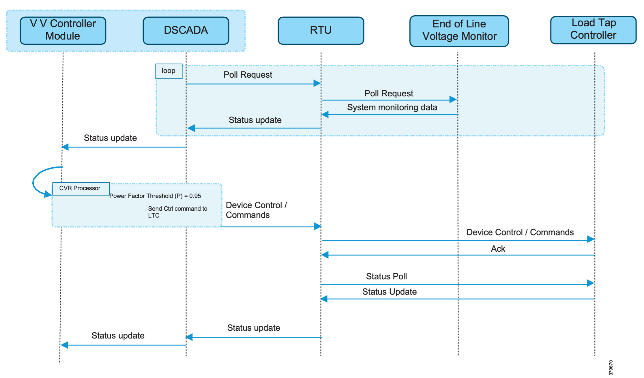
These figures detail the application flow between different components for power factor regulation:
1. RTU polls event class data to the following devices:
a. Substation meter: Polls measured Value (Short Floating Point) registers (0 to 4).
b. All CBCs: Polls measured Value (Short Floating Point) (0) and double point command (0).
c. End-of-line voltage monitor: Polls measured Value (Short Floating Point) register (0).
2. The Volt/VAR Optimization processor analyzes the data received from these devices and decides on a control command based on the power factor calculation.
3. The control command is sent from SCADA to the RTU, which then sends it to the CBCs to close Capacitor Bank Controller N by writing to a Control Relay Output Block (CROB) command register using the T104 (IP packet-based IEC-104) protocol.
4. Repeat Data Polling (from RTU): The RTU again polls the following devices:
a. Substation meter: Polls measured Value (Short Floating Point) registers (0 to 4).
b. All CBCs: Polls measured Value (Short Floating Point) (0) and double point command (0).
c. End-of-line voltage monitor: Polls measured Value (Short Floating Point) register (0).
5. All these steps are repeated for all CBCs along the feeder line to maintain a Power Factor value close to 1.
Fault, Location, Isolation, Service Restoration (FLISR)
FLISR is a critical process for managing fault conditions (like power outages or short circuits) on the electrical grid. This process:
1. Fault detection: Identifies where and what kind of problem has occurred on the power line.
2. Fault isolation: Contains the problem to the smallest possible section of the grid, preventing it from affecting a wider area.
3. Service restoration: Brings power back to as many customers as possible, even while the faulty section remains isolated.
FLISR includes advanced capabilities like automatic sectionalizing and restoration and automatic circuit reconfiguration (automatically changing how power flows). These features enable Distribution Automation (DA) operations by coordinating field devices, specialized software, and dedicated communication networks. This coordination allows the system to automatically pinpoint the fault location and quickly reroute electricity. The goal is to prevent or minimize outages for customers.
Because FLISR operations involve rerouting power, they typically require feeder configurations that offer multiple paths to single or multiple other substations. This design creates backup power supplies for customers located both upstream and downstream from a downed power line, a fault, or any other grid disturbance.
The benefits of implementing FLISR are significant:
● For consumers: They experience minimal power outages, leading to greater satisfaction.
● For utilities providers: They improve key performance indicators like the System Average Interruption Duration Index (SAIDI) and the System Average Interruption Frequency Index (SAIFI). This also helps them avoid financial penalties from regulators.
FLISR application control can be implemented in different modes:
● Supervised Mode: In this mode, the system provides fault information to the operator, but no automatic control actions are taken. The operator must manually initiate all control actions. This approach results in longer restoration times.
● Semi-Automatic Mode: This mode combines automatic and supervised control. The DA system automatically isolates the fault and handles the restoration for the upstream section (the part of the grid between the substation and the faulted section). Manual restoration is then performed for the downstream section (the part between the fault and the end of the feeder).
This guide focuses on the Semi-Automatic mode. In this mode, communication occurs between IEDs in the field and the Distribution Management System (DMS) application located in the control center.
● Fully Automatic Mode: In this most advanced mode, both fault isolation and service restoration happen automatically without any intervention from a dispatcher. Communication occurs directly between a group of related IEDs. Restoration is extremely fast (less than 1 second), but this mode is typically complex to deploy.
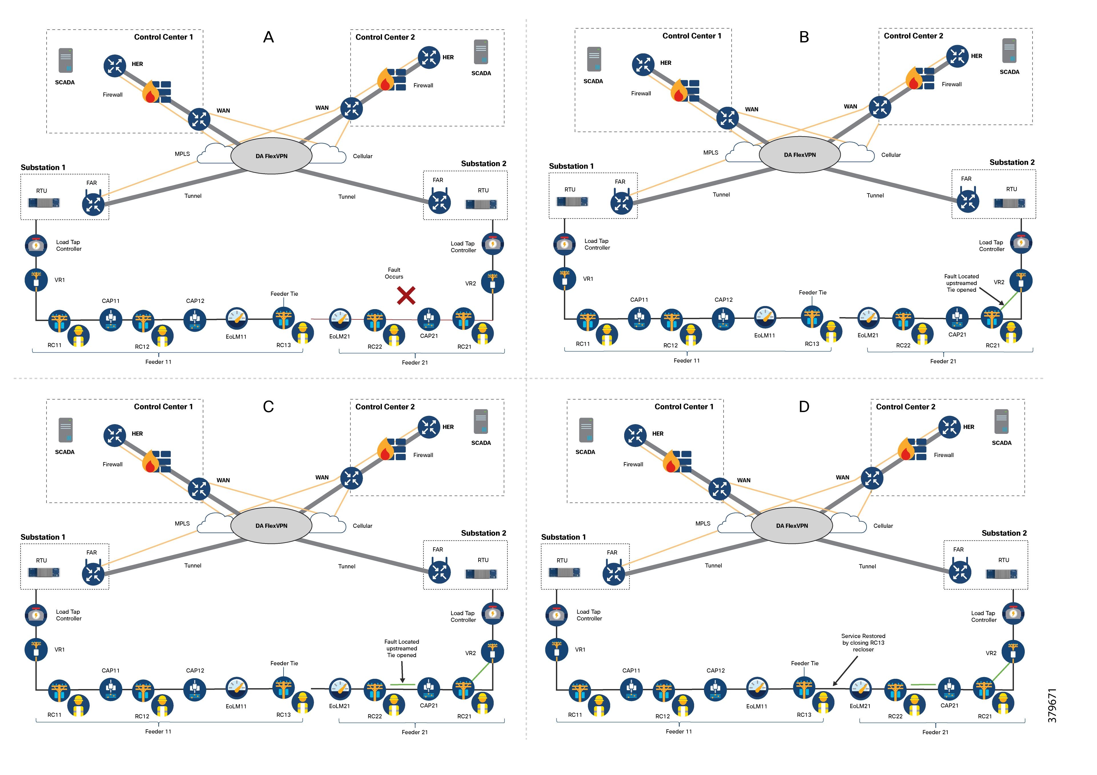
Parts A, B, C, and D of the following figure illustrate how FLISR operations function:
1. Part A: The FLISR system first locates the fault. This is usually done using line sensors that monitor electricity flow, measure the strength of fault currents, and communicate these conditions to other devices and grid operators.
2. Parts B and C: Once the fault is located, FLISR opens switches on both sides of the fault: one switch immediately upstream (closer to the power source, as shown in part B), and one switch downstream (further away, as shown in part C).
3. Part D: With the faulty section of the feeder now isolated, FLISR then closes the normally open tie switches that connect to neighboring feeders. This action re-energizes the healthy portions of the feeder ,and restores service to all customers connected to these unfaulted sections by drawing power from another substation or feeder.
These are the key devices and systems involved in FLISR operations:
● Recloser: A self-contained device that detects and interrupts excessive current conditions and then automatically recloses (restores) the power line.
● Sectionalizing Switch or Remote Control Switch (RCS): These devices can break loads or interrupt a fault.
● Remote Fault Indicator (RFI): A component used to detect and signal the presence of faults on the line.
● Distribution Management System (DMS): This intelligent application resides in the DSO (Distribution System Operator) Control Center. It acts as the brain of the FLISR system, performing the logic for circuit reconfiguration.
The following figure shows a parallel feeder distribution system. In this setup, two distribution feeders originate from two different Secondary Substations, and each feeder has an associated recloser.
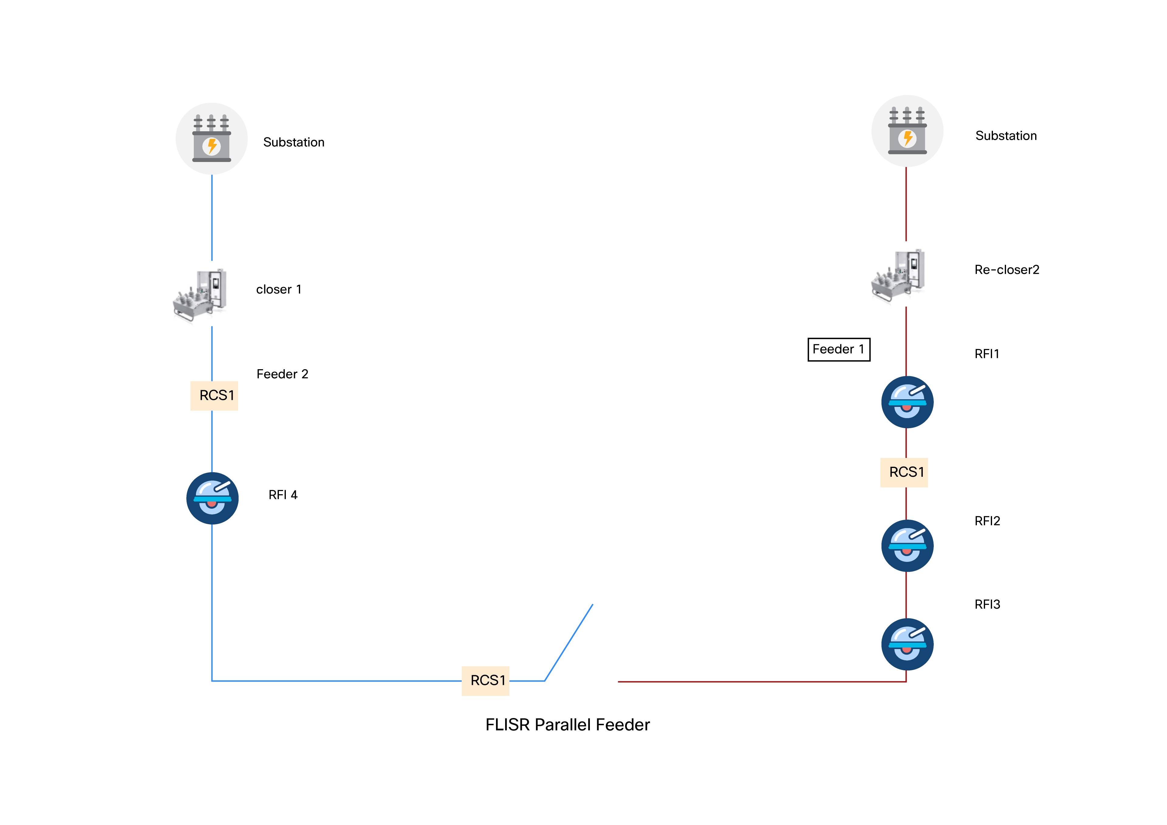
Remote Fault Indicators (RFIs) and Remote Control Switches (RCSs) are distributed across both feeders. RCS3 is usually an open switch by default.
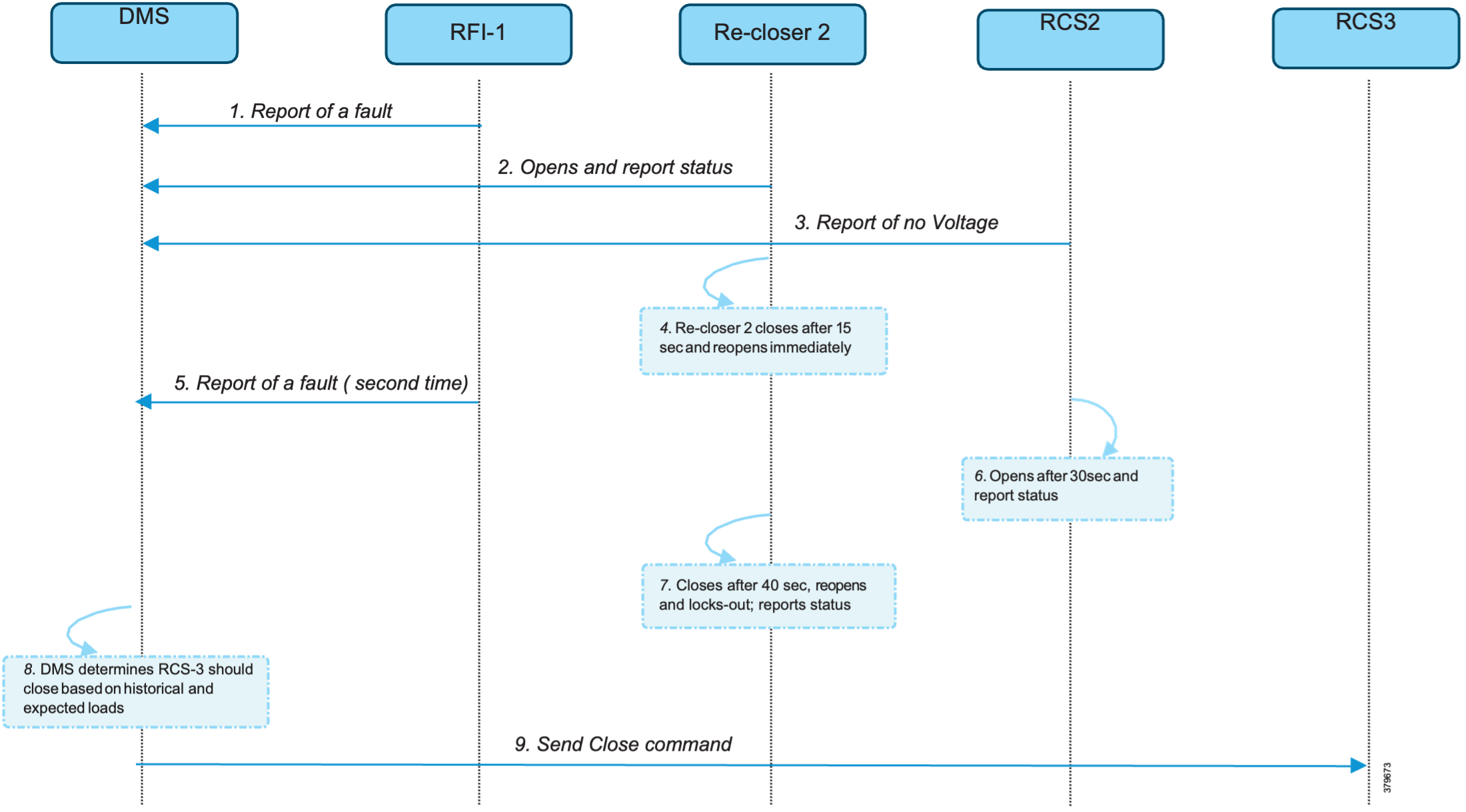
In Figure 11, the application flow demonstrates direct communication from feeder devices to the DMS application in the DSO Control Center. The process is summarized here:
1. Remote Fault Indicator (RFI) 1 reports to the DMS whenever it detects a fault.
2. Recloser2 opens and sends a report to the DMS when it encounters a temporary fault.
3. Recloser2 opens and sends a report to the DMS when it encounters a permanent fault.
4. RCS 2 reports a no voltage status to the DMS.
5. RCS 2 opens if it encounters faults a second time and sends a report to the DMS.
6. The DMS issues a command to close RCS 3.
7. The DMS initiates a periodic poll (every minute) to gather data from all feeder devices.
8. The DMS initiates a solicited periodic poll (once every 5 minutes) for all feeder devices.
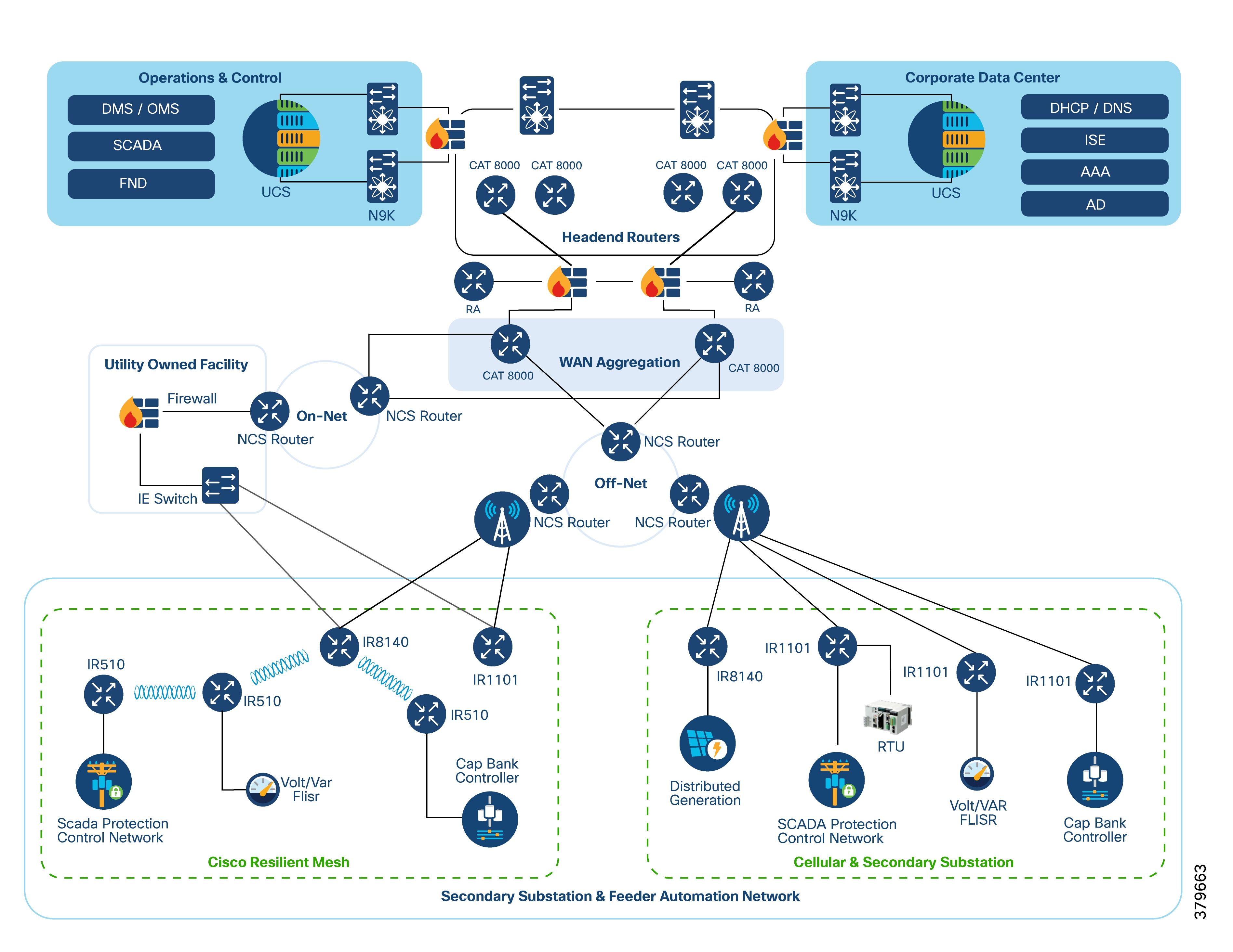
This chapter provides an overview of the Cisco Distribution Automation solution architecture, covering:
1. Where different components are placed within the network.
2. The overall solution architecture.
3. The specific components that make up the solution.
The DA Solution is a specific part of the broader FAN solution architecture. It follows a similar two-tier network structure:
1. The WAN tier connects the control center block with the Secondary Substation block or the field area block.
2. In turn, the field area or Secondary Substation blocks connect to utility device blocks using various last-mile connectivity methods such as Ethernet, Serial, or Wi-Fi.
The control center block functions as a data center for Distribution System Operators (DSOs). These blocks are often organized for specific regions (called Regional Network Operating Centers or NOCs).
Regional NOCs host various SCADA applications necessary for centralized management of different use cases, as discussed in the Distribution Automation Use Cases section.
The control centers house the Headend Router (HER) in a clustering mode. In the Cisco DA solution architecture, Cisco Catalyst 8500 series routers are deployed as the HERs. The HER's role is to:
● Terminate and aggregate IPSec tunnels from various DA Gateways and SSRs.
● Enforce Quality of Service (QoS) and security policies.
The control centers also host the Cisco IoT Field Network Director (FND), which is the network management system used for managing various gateways. Additionally, it includes Certificate Authorities that support RSA and elliptic-curve cryptography (ECC) encryption, and an AAA server (Authentication, Authorization, and Accounting) for user and device management.
A key component of the Secondary Substation block is the Secondary Substation Router (SSR). The Cisco IR1101 router can be deployed as an SSR. These routers connect and aggregate traffic from various IEDs and RTUs present in Secondary Substations, sending it to one or dual Control Centers.
The Cisco IR1101 is designated as the DA cellular gateway for deployment in the Field Area block. In most cases, one DA Gateway is installed and associated with a DA Controller. These gateways primarily connect to the backhaul network using cellular or Ethernet links. The management of these DA Gateways is handled through the Cisco IoT FND.
These DA gateways are easily set up using Plug-and-Play bootstrapping and ZTD mechanisms offered by Cisco IoT FND. ZTD of DA Gateways is covered in detail in the Network Management System section.
DA Gateways can be provisioned automatically based on the application use cases and the type of last-mile connectivity to the utility control devices. They can also be re-provisioned remotely using Day N re-provisioning options available in Cisco IoT FND.
The utility devices block contains various DA controllers, such as voltage regulator controllers, recloser controllers, remote control switches, and capacitor bank controllers. These controllers connect to DA Gateways via either Ethernet or serial interfaces (RS232 and RS485).
Distribution Automation – ICT Design Options
The DA architecture in this guide distributes SCADA services across multiple Regional Control Centers to enhance headend high availability for large-scale aggregation.
This section outlines key architectural deployment models that improve scalability, resilience, and operational flexibility in a modern distribution automation environment.
The following deployment topologies are discussed in this section:
● Centralized NMS with Regional SCADA Control Centers
● Dual Data Center with BGP-based Router Advertisement
Centralized NMS with Regional SCADA Control Centers
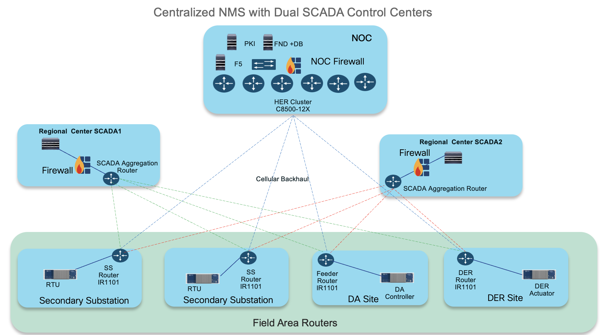
Centralized NMS at the NOC
All operations related to device onboarding, initial setup (Day 0), and ongoing (Day N) management, and network monitoring are centrally managed from the Network Operations Center (NOC). This centralized approach provides:
● Consistent visibility
● Streamlined control
● Simplified workflows across the deployment
Multiple Regional SCADA Centers
SCADA systems are distributed across several Regional Control Centers. This strategy offers significant advantages:
● Reduced response latency
● Localized fault domains
● Improved operational continuity
Scalable IKEv2 CLB Cluster Design for the Headend
IKEv2 cluster-based aggregation (HER clustering)
For large-scale deployments, Cisco recommends grouping multiple HERs into an IKEv2 CLB (Cluster Load Balancing) configuration. A single cluster comprising six or more Cisco Catalyst 8500-12X routers, can support up to 50,000 Cisco IR1101 devices.
Horizontal scalability beyond 50,000 endpoints
To accommodate more than 50,000 endpoints, you can deploy multiple IKEv2 CLB clusters in parallel. For example, Cluster A handles the first 50,000 Cisco IR1101 devices, while Cluster B manages an additional 50,000 Cisco IR1101 devices.
Geographically redundant HER clusters
To ensure continuous operation and protection against disasters, you can deploy additional HER clusters in geographically separate data centers. This setup provides:
● Failover capability: If one data center goes down, traffic can automatically switch to another.
● Minimized impact: Localized outages have less effect on overall service.
Multi-tunnel connectivity from the Cisco IR1101
Each Cisco IR1101 device establishes three independent IPsec tunnels to different destinations: one tunnel to the NOC and two tunnels to two distinct regional control centers.
Tunnels to the Network Operations Center (NOC)
Tunnel 10: Dedicated to NMS (Network Management System) traffic.
This tunnel is used by Cisco IoT FND for secure management, configuration, and monitoring of the Cisco IR1101 devices.
Tunnels to Regional SCADA Control Centers
Tunnel 11: Connects to Regional SCADA Control Center 1.
Tunnel 12: Connects to Regional SCADA Control Center 2.
These tunnels carry SCADA data traffic from field devices to their respective regional SCADA systems, as well as other utility decision and control systems.
Security: All these tunnels are protected using IPsec encryption. This ensures the confidentiality, integrity, and authenticity of traffic as it travels across various networks, including private or public cellular or internet links, whether they are trusted or untrusted.
50,000 Tunnel Scaling with HER Cluster Load Balancing
Table 1. Roles of HER cluster components
| Components |
Role |
Description |
| Cisco IR1101 |
● Cisco Cellular Gateway
● Secondary Substation Router
● Feeder Router for DA sites
● DER Router
|
Multiple utility controller devices could be connected to single IR1101 using IPv4/IPv6/Serial |
| C8500-12X |
Head End Router (HER), as a single router or as part of HER cluster. |
Deployed in cluster of 5+1 C8500-12X routers. |
| Cisco IoT FND |
Network management system used in this solution. |
Used for onboarding and management of Cisco IR1101s using Plug and Play and Zero Touch Deployment. |
| Postgres |
Database used by NMS for this 50k router scale. |
Part of Cisco IOT FND OVA. |
Dual Data Center Design Using BGP Route Advertisement
This design helps you build a highly reliable and resilient network. It uses Border Gateway Protocol (BGP) as the main routing protocol, which helps devices stay connected and allows for flexible return path control.
By using BGP features like the Multi-Exit Discriminator (MED), the network can pick the best path and automatically reroute traffic if there’s a problem on the main path. This setup is ideal for customers who require high availability, low latency switchovers, seamless failover, and intelligent traffic engineering.
The design connects two geographically redundant data centers in an active/active topology. Both data centers are always active, ensuring that applications stay available and that data returns via the best possible path.
Cisco IR1101 routers are used at the network edge. Each router uses two LTE connections, each with a different service provider, to ensure connectivity even if one provider fails. Secure tunnels connect the routers to both data centers.
The routers automatically share the routes needed to set up BGP neighbors, using IKEv2 prefix injection. This means there’s no need to use a separate internal routing protocol, making the setup simpler and reducing operational costs.
Note: BGP routing uses some cellular data, but this is a worthwhile trade-off for the improved path selection, dynamic failover, and quick recovery that BGP offers.
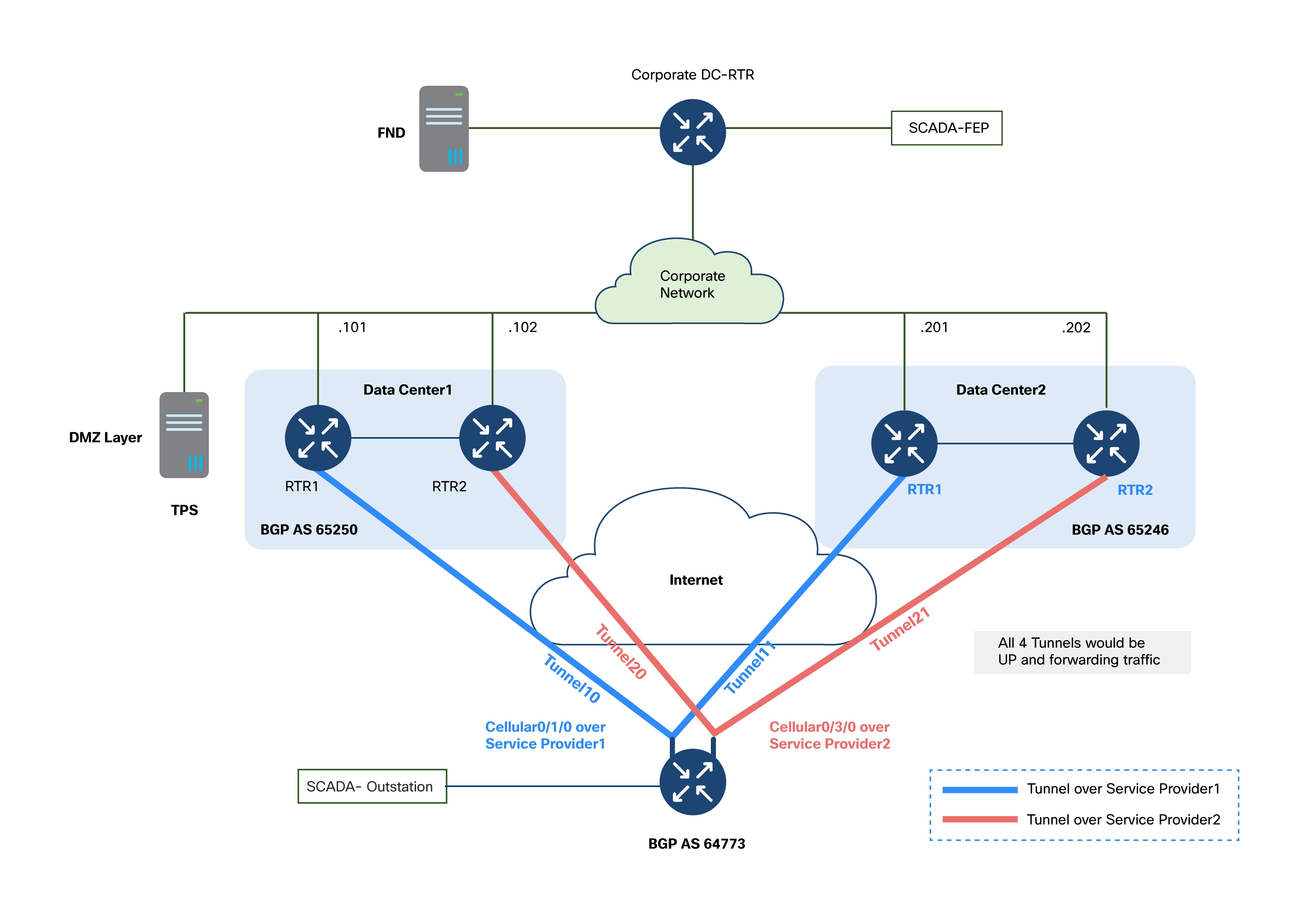
BGP Autonomous System (AS) Assignments
Each part of the network uses its own BGP Autonomous System (AS) number for clarity and control:
● Data Center 1: AS 65250
● Data Center 2: AS 65246
● Cisco IR1101 (Field Router): AS 64773
● Corporate Network (connects the two data centers): May use a separate AS, based on your organizational requirements.
1. Two Separate Data Centers (DC1 and DC2)
a. Located in different physical locations for geographic redundancy.
b. Each data center uses its own BGP AS for easier management and policy control.
c. Both data centers connect to the corporate network, which may have its own AS.
d. The corporate network hosts critical applications like Cisco IoT Field Network Director (FND) and customer-specific OT applications (e.g., SCADA FEP).
e. Cisco IR1101 routers set up BGP sessions (eBGP) with routers in both data centers.
f. This design uses manual tunnel-to-peer mapping of tunnels for better control over traffic routing and redundancy:
i. Tunnel10: Connects to Data Center 1 Router 1 via Cellular0/1/0
ii. Tunnel11: Connects to Data Center 2 Router 1 via Cellular0/1/0
iii. Tunnel20: Connects to Data Center 1 Router 2 via Cellular0/3/0
iv. Tunnel21: Connects to Data Center 2 Router 2 via Cellular0/3/0
2. Cisco IR1101 with Dual LTE Modules
a. Each LTE module can use a different cellular provider, ensuring connectivity if one provider fails.
b. The router keeps tunnels to both data centers active at the same time.
3. BGP Control Plane
a. Dynamic Path Selection: BGP automatically chooses the best path and can quickly reroute traffic if there’s a failure.
b. Seamless Failover: If a link or data center fails, BGP quickly finds the next best path, minimizing downtime.
c. Traffic Engineering: BGP attributes like MED help direct traffic to the preferred data center in normal and failover conditions.
This solution is designed to keep services running even if there are multiple kinds of network failures.
Table 2. Failure scenarios and impact mitigation
| Failure scenario |
Impact mitigation |
| Loss of one LTE service provider |
Traffic is automatically rerouted using an alternate provider |
| Failure of one LTE module on the Cisco IR1101 |
Second LTE module maintains tunnel connectivity |
| Tunnel failures (up to three GRE/IPSec tunnels) |
BGP reroutes traffic using available tunnels |
| Complete Data Center outage |
Full failover to an alternate data center, with preserved reachability |
Recommended Topology: Active/Active
● Use an active/active setup between the IR1101 routers and both data centers.
● All four tunnels from each Cisco IR1101 router to the data centers should always be up.
● Traffic can be split or steered based on application type, policies, or network latency.
● This setup maximizes availability and resource usage.
● Return Path Selection: BGP MED values from each data center’s HERs decide which data center is preferred for returning traffic to the IR1101 routers and utility applications.
● Automatic Failover: If a link or data center goes down, BGP quickly updates the path, so no manual work is needed.
● Return Path Control: Ensures that traffic between corporate applications and Cisco IR1101 routers returns through the preferred data center, even if routing is asymmetric.
Deployment Topology Components
Table 3. Deployment topology components
| Device |
Role |
Description |
| Cisco IR1101 |
● Cisco Cellular Gateway
● Secondary Substation Router
● Feeder Router for DA sites
● DER Router
● Dual LTE Gateway
|
Multiple utility controller devices could be connected to single Cisco IR1101 using IPv4/IPv6/Serial. |
| C8500 |
Data Center routers in both data centers |
Deployed in non-clustering mode. |
| Cisco IoT FND |
Network management system used in this solution. |
Used for onboarding and management of Cisco IR1101s using Plug and Play and Zero Touch Deployment. |
| Postgres |
Database used by NMS |
Part of Cisco IOT FND OVA. |
Distribution Automation Solution Architecture
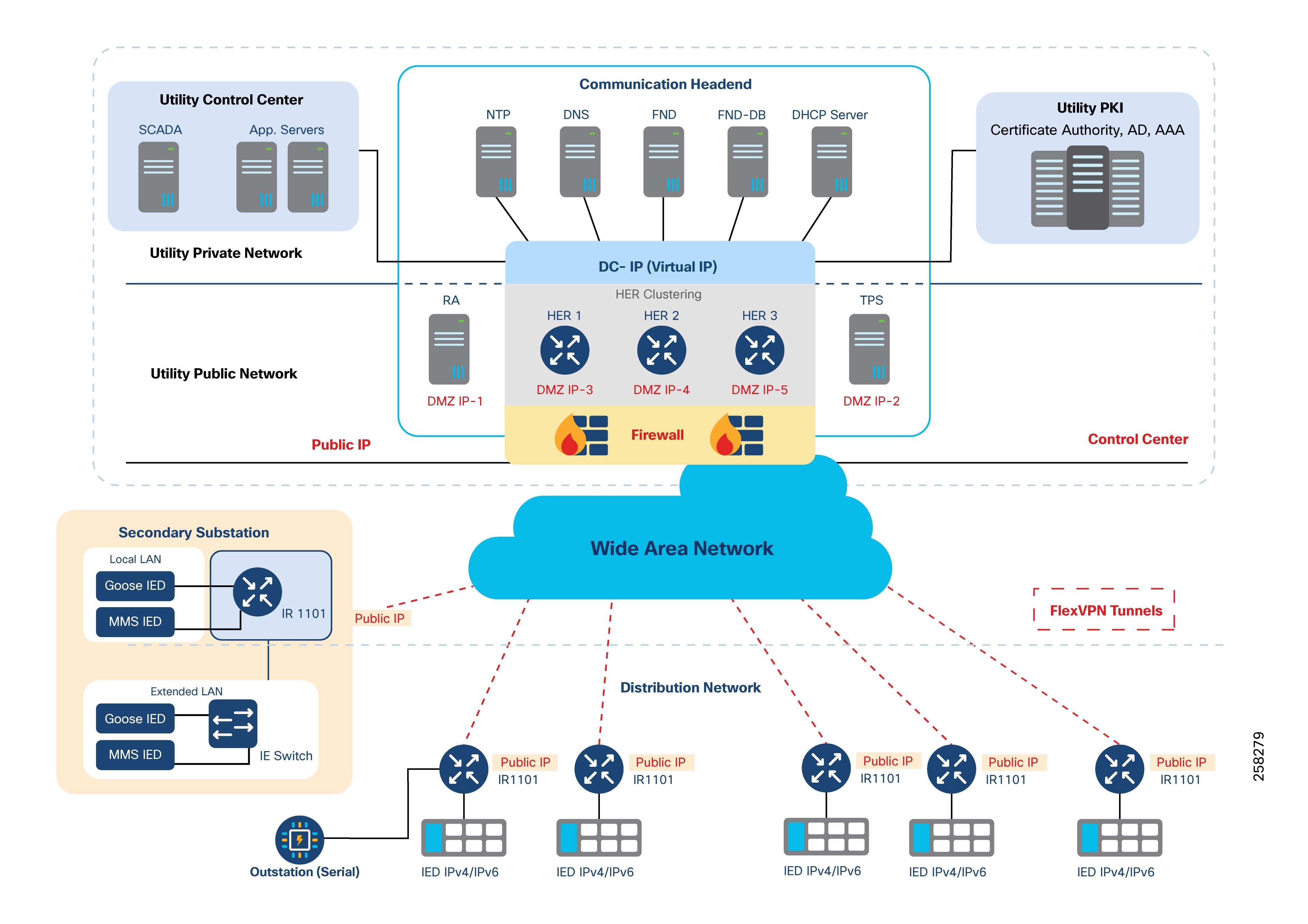
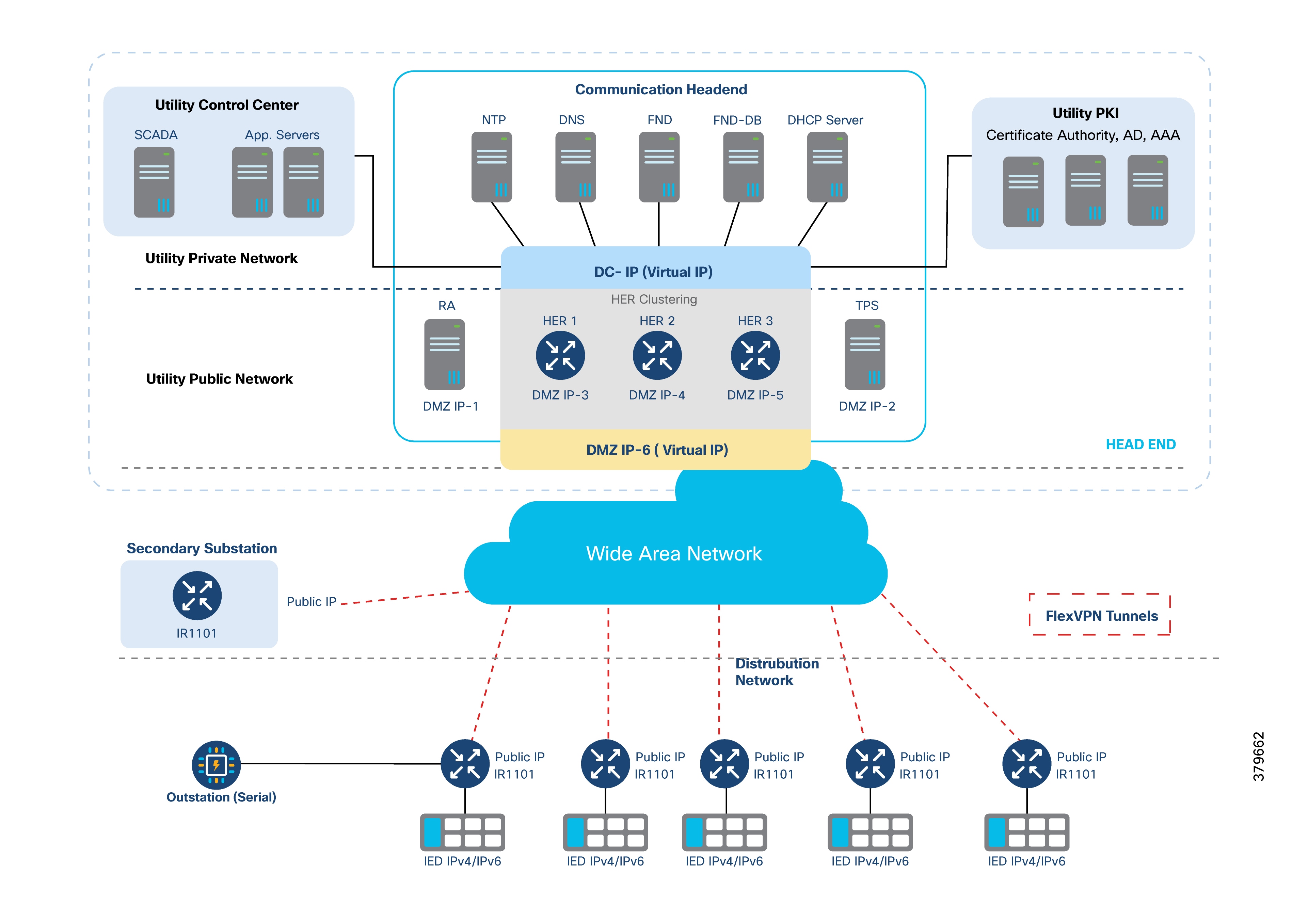
The architecture is centralized, with a control center (regional DSO NOC) that manages communication, security, utility, and network applications for the region.
The control center is divided into three zones by a firewall:
1. External Zone
2. DMZ Zone, which contains:
a. An HER interface (set up in clusters for redundancy and scalability)
b. The Registration Authority (RA) for authentication and authorization using the AAA server
c. The TPS which acts as a proxy for the NMS Cisco IoT FND
3. Internal Zone, which contains:
a. NTP
b. DNS
c. DHCP
d. NMS and edge application management using Cisco IoT FND, Field Network Director Database (FND-DB), PKI elements such as CA, Active Directory, and AAA
e. Distribution Automation applications (like SCADA and DMS)
The DA application bidirectional flow includes three flows:
1. SCADA <----> RTU <----> IEDs
2. SCADA <----> IEDs
3. IEDs <----> IEDs
The application bidirectional traffic flow from field IEDs to SCADA in the control center uses the RTU in the Secondary Substation. Application traffic is depicted by the yellow arrow in the following figure.
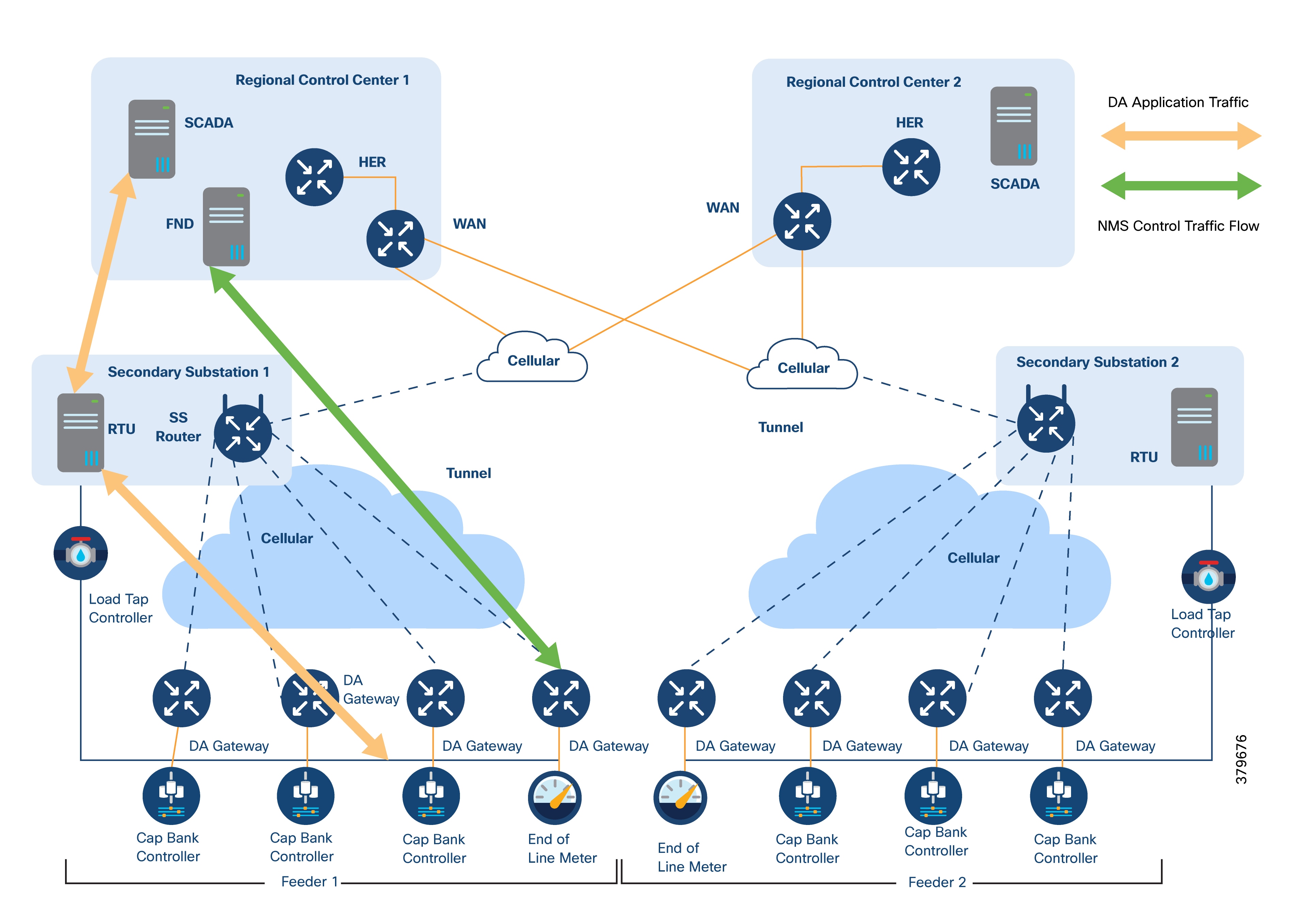
The ICT solution design for this application flow includes:
● DA Gateways are installed one-to-one with controllers and the last-mile network. They connect using either Ethernet or serial links.
● DA Gateways have public WAN connectivity, typically using cellular backhaul.
● All application traffic is encrypted using FlexVPN. In this design, VPN tunnels from the DA Gateways terminate at the SSR.
● The WAN IP address at each Secondary Substation is static.
● SSRs forward traffic from IEDs to the RTUs located at the same site.
● The RTU processes this data as either unsolicited reports or responses to control commands.
● The RTU then forwards DA application traffic to the SCADA system in the control center.
● To securely transport this traffic, the SSR establishes an encrypted FlexVPN tunnel to the HER located in the control center.
For redundancy, two VPN tunnels are established from the SSR to two different regional control centers. Both tunnels operate in active/active mode.
Separate control traffic flows from the NMS (Cisco IoT FND) to DA Gateways and SSRs. (This is shown as a green arrow in Figure 14.)
DA Gateways have:
● One FlexVPN tunnel for NMS application traffic.
● A separate FlexVPN tunnel for DA application traffic.
SSRs have:
● Two FlexVPN tunnels, each connecting to a different regional control center.
● Application and control traffic can share the same FlexVPN tunnel if desired.
Optionally, a third FlexVPN tunnel can be set up from the SSR to the HER, dedicated to control traffic.
As shown in the following figure, IEDs can directly communicate with the centralized SCADA system.
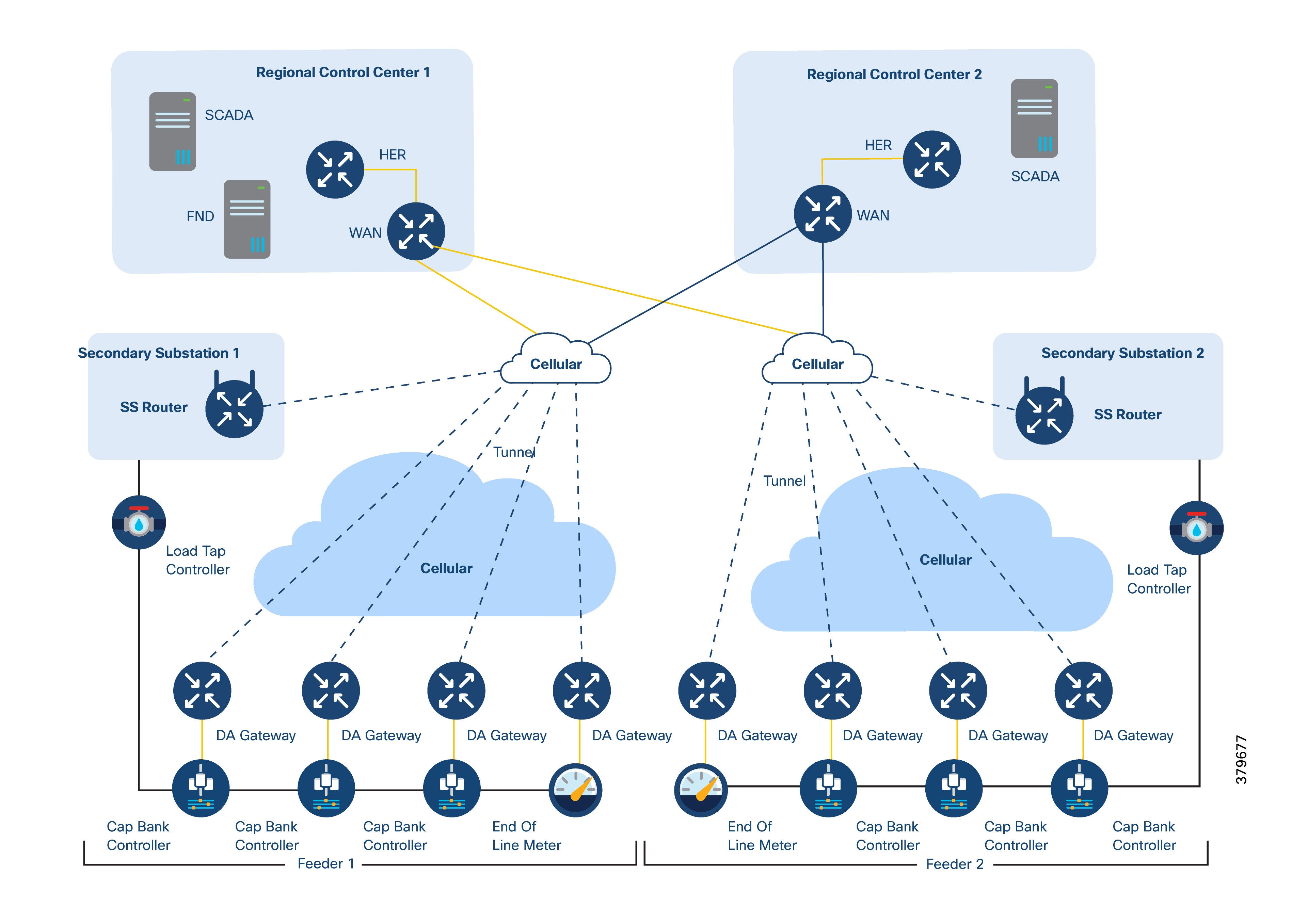
In this scenario:
● DA Gateways and SSRs connect directly to the HER at the regional control center using public WAN links.
● For redundancy, DA Gateways can maintain two active/active VPN tunnels to two regional control centers.
● Both DA application traffic and NMS control traffic can travel within the same FlexVPN tunnel.
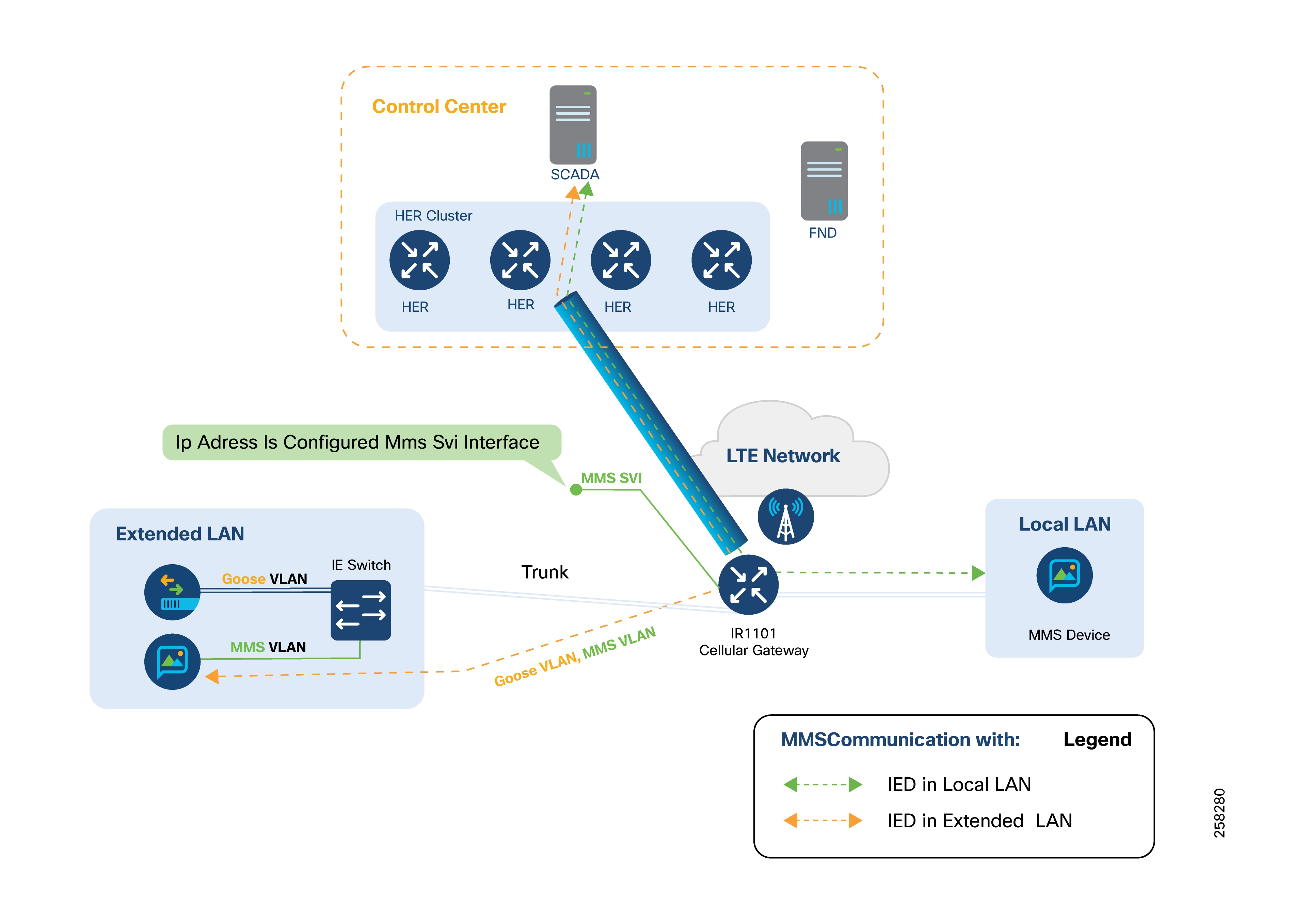
There are two main types of communication flows in this figure:
● From the control center to an MMS IED on the local LAN.
● From the control center to an MMS IED on the extended LAN (for example, IEDs at remote Distributed Energy Resource (DER) sites connected via fiber).
There are three ways IEDs communicate with each other:
● Peer-to-Peer Layer 2 Communication over a Layer 3 Cellular Network
● Locally-switched IED Communication
● Hub-switched IED Communication
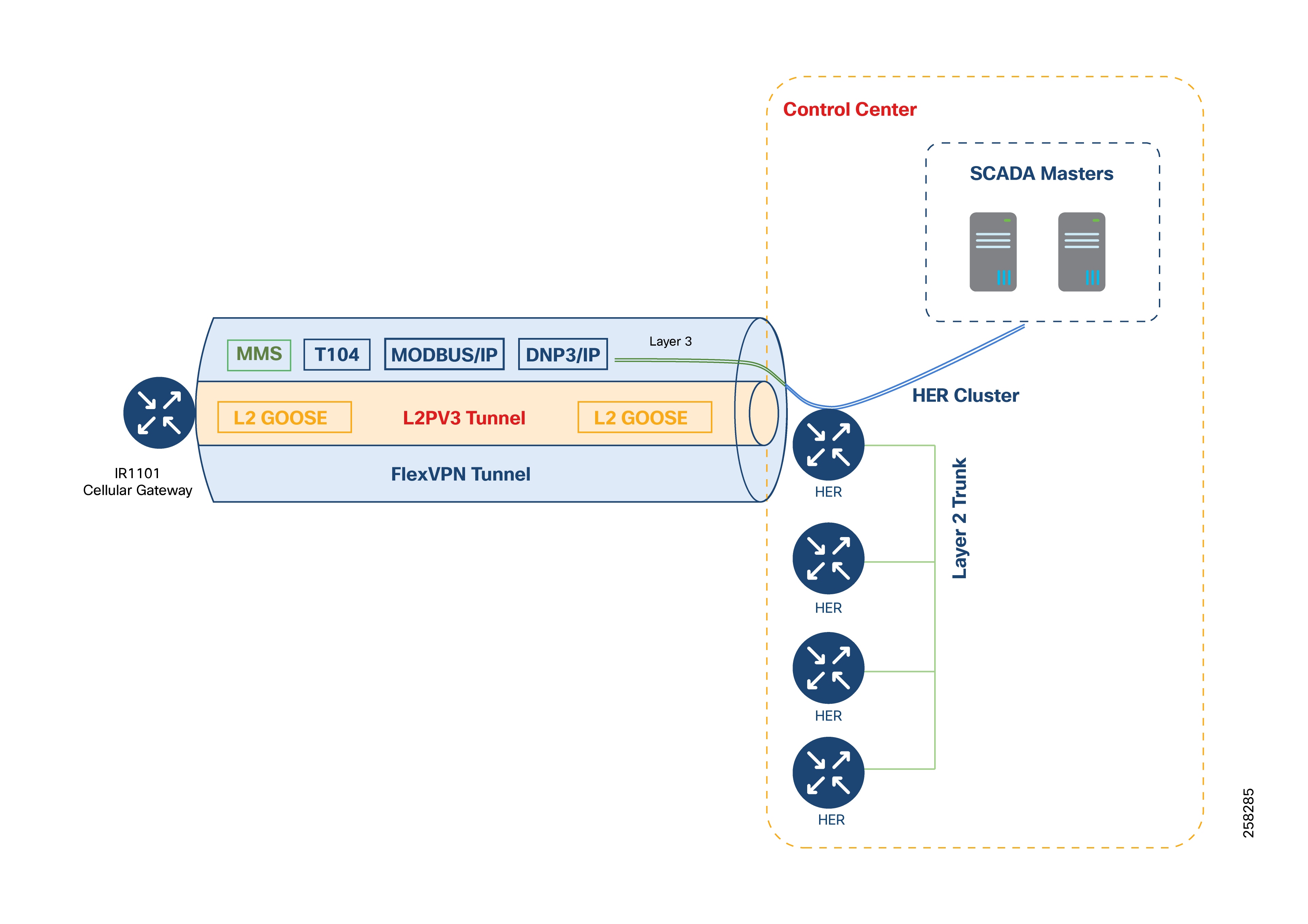
Peer-to-Peer Layer 2 Communication over Layer 3 Networks
GOOSE Messaging
IEC 61850 GOOSE (Generic Object Oriented Substation Event) is a protocol that uses Layer 2 Ethernet frames for fast and reliable messaging between IEDs in substations. This protocol ensures ultra-low latency and reliable communication for protection and control schemes.
The Challenge
When IEDs are located at different sites and connected over Layer 3 networks (like public/private cellular), traditional Layer 2 GOOSE messaging does not work, because Layer 3 breaks the broadcast domain.
Solution: Layer 2 Extension with Cisco IR1101 Gateways
Cisco Catalyst IR1101 routers support extending Layer 2 connections over Layer 3 networks. This allows GOOSE-enabled IEDs at different locations to communicate as if they are on the same Ethernet LAN.
How It Works: Layer 2 Emulation using VXLAN over FlexVPN
Cisco IR1101 gateways use VXLAN (Virtual Extensible LAN) and PIM multicast within a secure FlexVPN tunnel over a Layer 3 (cellular) network.
Technical Details:
1. VXLAN Overlay inside FlexVPN
● VXLAN wraps Layer 2 Ethernet frames (including VLAN tags) in UDP packets, allowing them to cross a Layer 3 network.
● Allows 802.1q tagged Ethernet frames from GOOSE-capable IEDs to be carried transparently over the cellular IP network.
● The FlexVPN tunnel provides an encrypted channel for the VXLAN traffic between Cisco IR1101 gateways, ensuring security and integrity.
2. Multicast Using PIM
PIM (Protocol Independent Multicast) enables efficient multicast forwarding of GOOSE messages within the VXLAN overlay.
3. Route Advertisement with IKEv2 Prefix Injection
● Required routes for the VXLAN overlay are shared using IKEv2 prefix injection during VPN setup.
● No need for extra routing protocols like BGP or OSPF, which keeps the network configuration simple.
Refer to Distribution Automation Direct Transfer Trip over Cellular for more details on deploying Direct Transfer Trip (DTT) and IEC 61850 GOOSE messaging solutions over cellular networks using Cisco platforms.
Locally-Switched IED Communication
In locally-switched IED communication, IEC 61850 Layer 2 GOOSE messages are exchanged between devices within the substation’s local LAN and devices in the extended LAN. The switching of these messages happens directly at the Cisco IR1101 cellular gateway, rather than at a central hub.
If you must send GOOSE messages to devices in other substations, the IR1101 can be configured to forward these Layer 2 messages to the Hub (HER). The hub then switches the messages to other substations as needed.
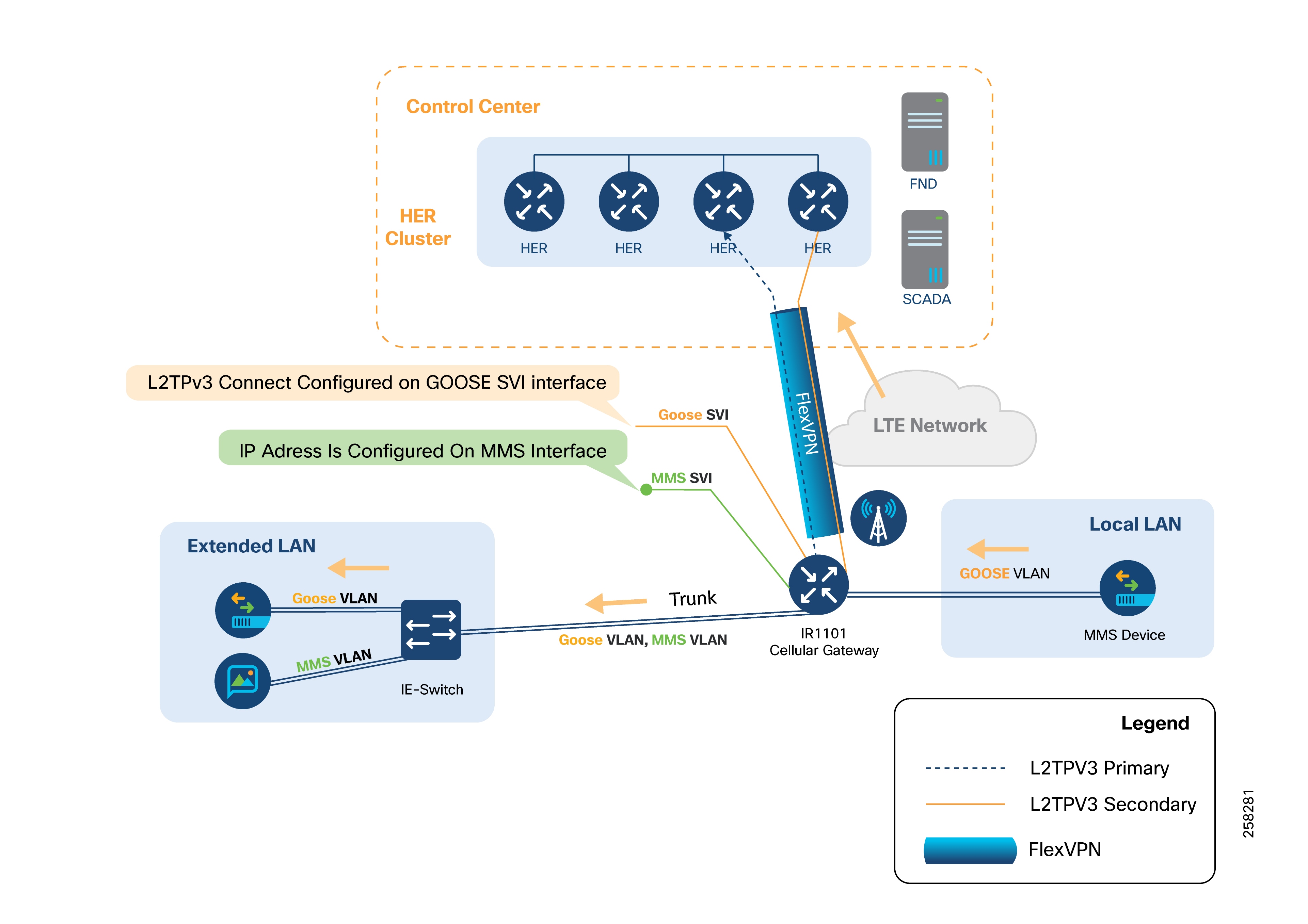
The LAN can be extended by connecting a Cisco Industrial Ethernet (IE) series switch to the SFP port on the Cisco IR1101’s expansion module. This SFP port functions as a Layer 2 trunk port, allowing both GOOSE VLAN and MMS VLAN traffic.
GOOSE devices can connect to the IE switch. If the GOOSE device supports VLAN tagging, configure the IE switch port as a trunk port for the required VLANs.
If the GOOSE device does not support VLAN tagging, configure the IE switch port as an access port to tag incoming GOOSE traffic with the appropriate VLAN.
On the Cisco IR1101, create an SVI for each relevant VLAN ID.
For MMS devices, connect them to the IE switch and configure the port as an access port to tag MMS packets with the MMS VLAN. Recommended Configuration:
● Connect the IE switch to the IR1101’s GigabitEthernet0/0/5 (SFP port) on the expansion module.
● Set this interface as a trunk port to carry multiple VLANs, supporting both Layer 2 GOOSE and Layer 3/MMS traffic.
● Multiple Layer 2 bridge domains can be created by configuring several GOOSE VLANs.
If there is a need to send Layer 2 GOOSE traffic to GOOSE devices in other substations, enable northbound Layer 2 connectivity to the hub by configuring an L2TPv3 pseudowire on the GOOSE SVI.
Layer 3 connectivity for MMS can be enabled by assigning an IP address to the MMS SVI.
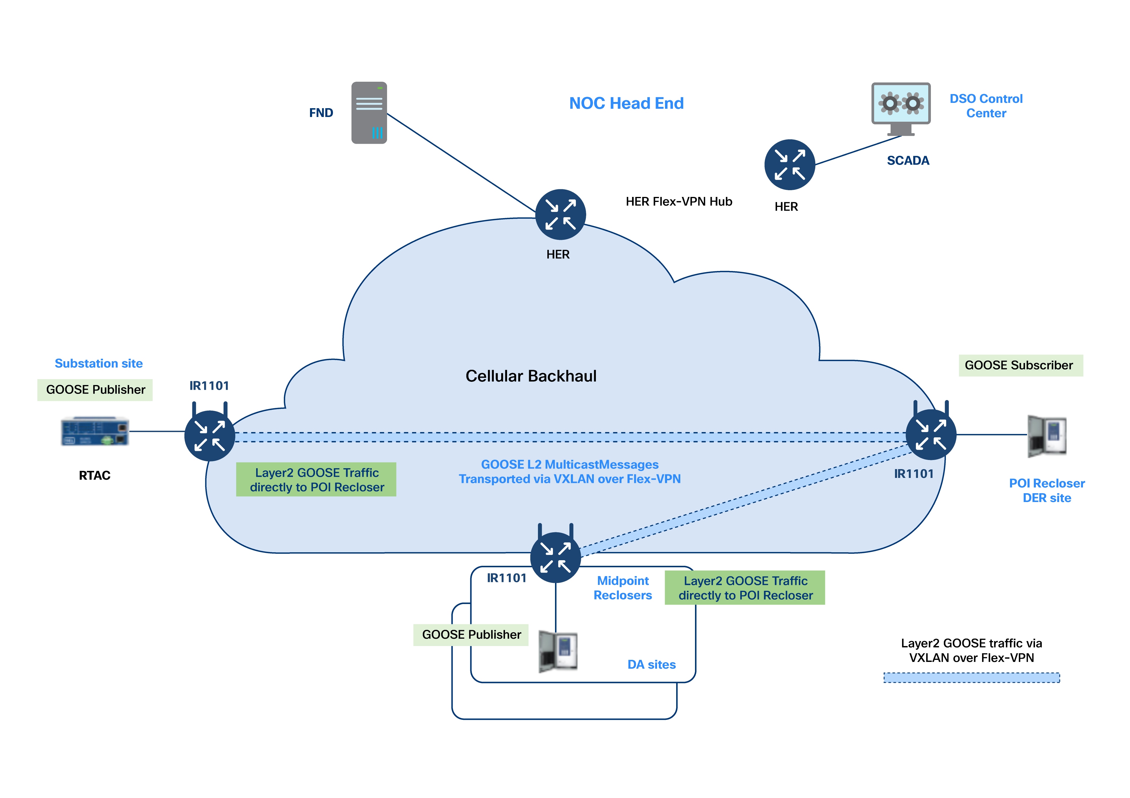
Hub-Switched IED Communication
In hub-switched IED communication, Layer 2 frames need to be sent between GOOSE IEDs connected to different Cisco IR1101 gateways, which are themselves connected over a Layer 3 cellular network.
To enable Layer 2 communication over the Layer 3 cellular network, an overlay Layer 2 infrastructure is created on top of the secure FlexVPN tunnel.
Hub-and-Spoke Architecture
The solution uses a virtual bridge with a hub-and-spoke topology. The control center (hub) bridges Layer 2 GOOSE messages between all connected DA cellular gateways (spokes).
When an IED connected to one DA gateway sends a GOOSE message, it is forwarded to the control center hub, which then distributes it to other GOOSE IEDs connected to other DA gateways.
Layer 2 GOOSE messages are securely transported over the cellular backhaul using the overlay infrastructure. The bridging operation happens centrally at the control center, enabling communication between IEDs at different substations.
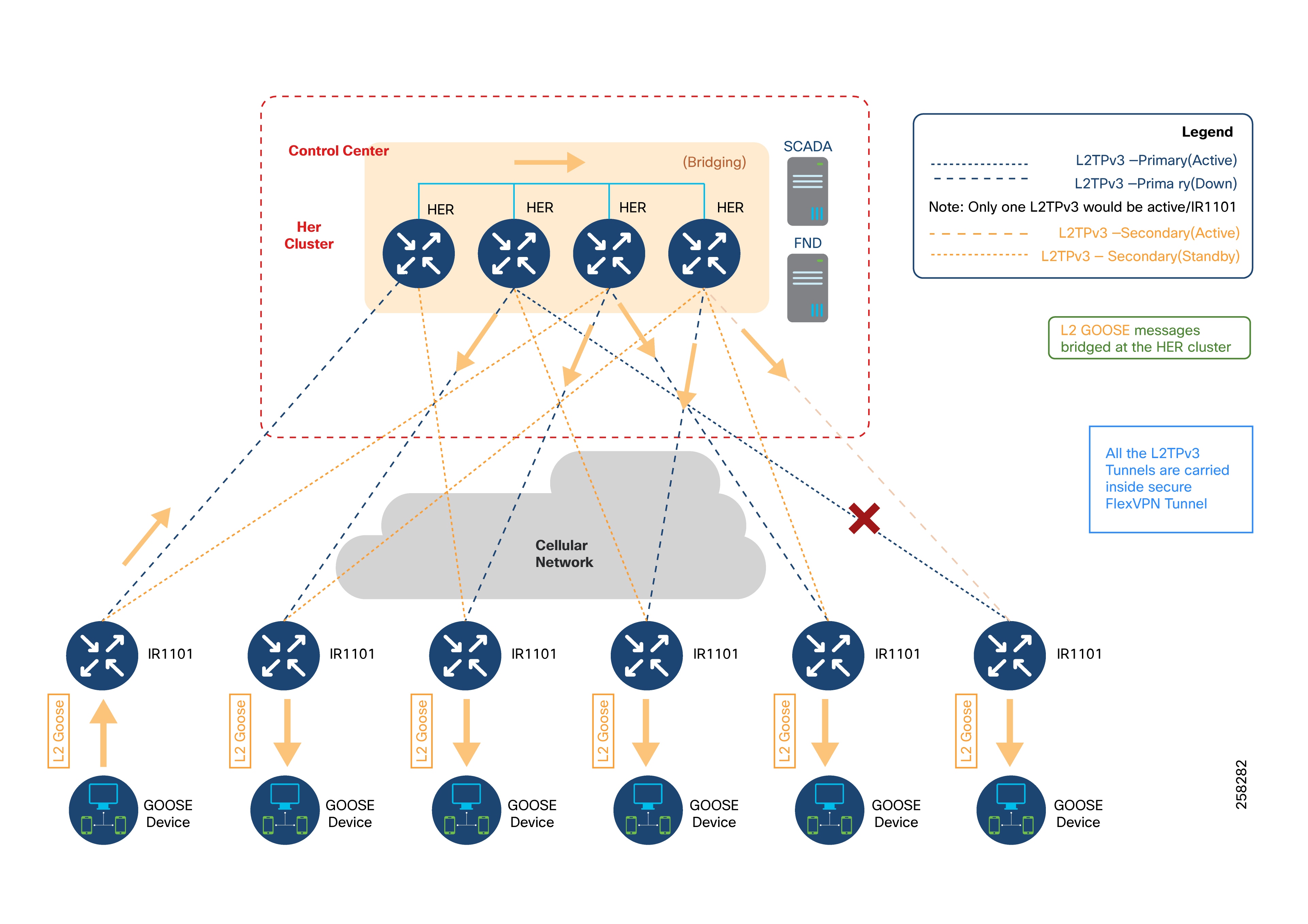
In the illustrated design, GOOSE messages generated by a device connected to the leftmost Cisco IR1101 are carried as Layer 2 frames using an L2TPv3 pseudowire. This tunnel transports the message to the HER cluster at the control center, which acts as a Layer 2 bridge. The HER cluster then bridges this GOOSE message to all other IR1101 gateways using their respective pseudowires.
How it works:
● L2TPv3 pseudowires are set up on the GOOSE SVI (Switched Virtual Interface) of each IR1101 gateway.
● Each pseudowire terminates on the interface of the HER that faces the data center.
● At the HER cluster, Layer 2 frames are bridged either using a physical loopback cable or through an external switch.
Layer 2 Bridging Process:
1. The HER removes the VLAN tag from incoming GOOSE frames and places them into a bridge-domain.
2. The bridge-domain connects all L2TPv3 pseudowires from multiple IR1101 gateways, allowing Layer 2 GOOSE messages to reach all other connected substations.
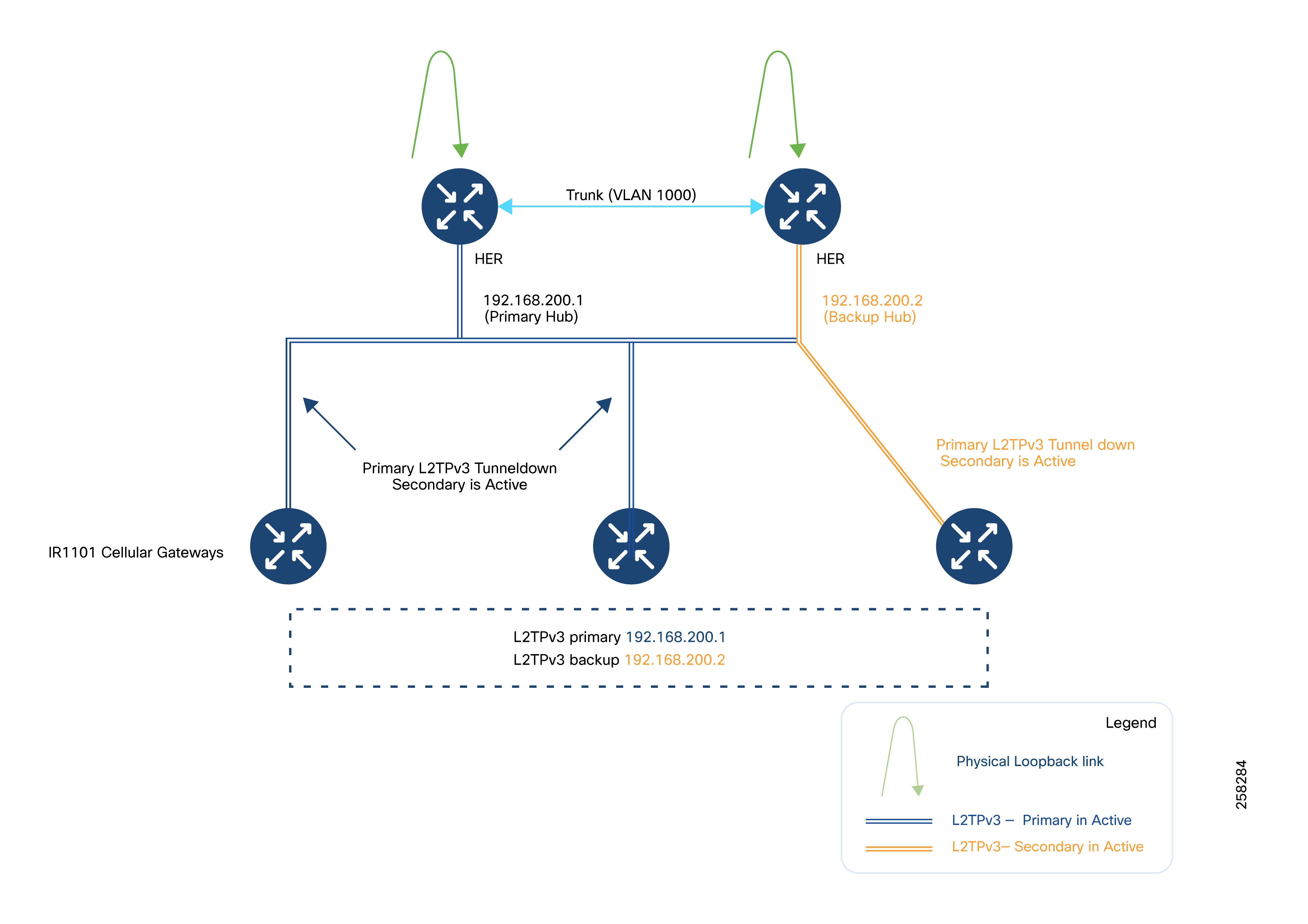
L2TPv3 Pseudowire Resiliency
Each Cisco IR1101 is configured with an active L2TPv3 pseudowire to one HER, and a backup pseudowire to another HER.
If the primary pseudowire fails, the backup pseudowire automatically becomes active, ensuring continuous communication. Only one pseudowire is active at any time.
For example, the last IR1101 the the figure above has its primary pseudowire connected to HER2 and its backup to HER4. If the primary fails, the backup takes over.
IEC 61850 GOOSE Bridging Flow:
1. The six IR1101 gateways in the diagram are labeled IR1101-1 (leftmost) to IR1101-6 (rightmost). The distribution of pseudowires among the HERs is demonstrative.
2. A Layer 2 GOOSE message from IR1101-1 is sent to the control center and arrives at HER1.
3. HER1 uses a physical loopback or an external switch to enable bridging within the bridge-domain, which extends to the other HERs. We recommend using an external switch to extend the Layer 2 network connecting the HERs.
4. Through this extended bridge-domain, the Layer 2 frames are sent to HER2, HER3, and HER4.
5. HER2 sends the frame to IR1101-2 via the active pseudowire.
6. HER3 forwards the frame to IR1101-3 and IR1101-5 over their respective active pseudowires.
7. HER4 forwards the frame to IR1101-4 using the active pseudowire.
8. HER4 also forwards the frame to IR1101-6, using the backup pseudowire because the primary is down.
HER as L2TPv3 Hub for Creating Layer 2 Bridge Domain
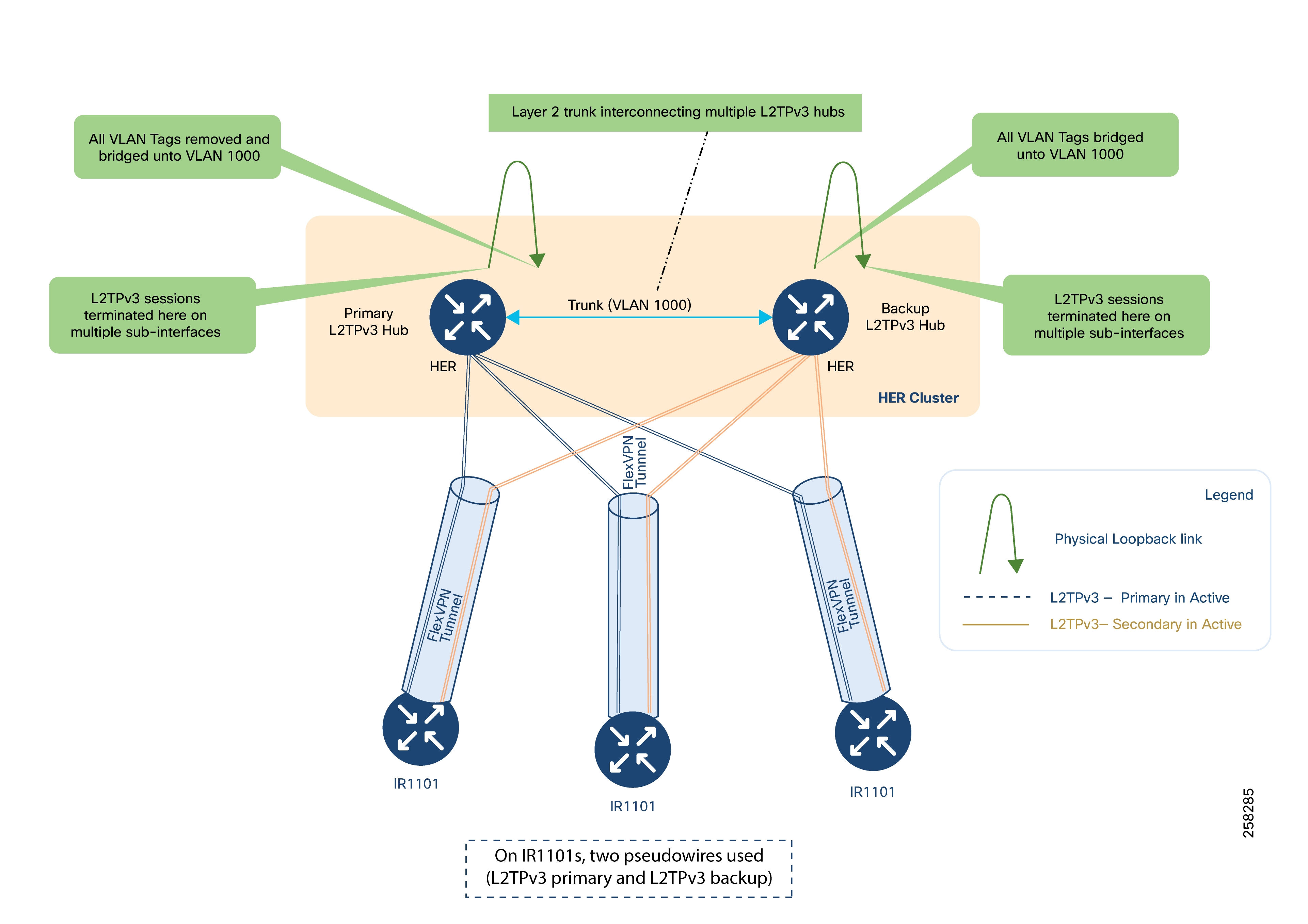
The FlexVPN tunnel from each IR1101 can terminate on any HER in the cluster. Each IR1101 connects its active pseudowire to one HER and its backup to another HER.
Each HER includes a physical loopback link and trunk ports that interconnect all HERs, allowing VLAN traffic (for example, VLAN 1000) to be bridged across the cluster.
The data center-facing interface of the HER removes VLAN tags and bridges frames into bridge-domain 1000.
The trunk ports between HERs extend this bridge-domain across the entire cluster.
The following figure illustrates the logical hub-and-spoke topology: HERs serve as hubs and IR1101s as spokes.
IR1101s may have either the primary or backup pseudowire active for Layer 2 communication.
In the following figure, L2TPv3 pseudowires encapsulate GOOSE Layer 2 traffic, which is itself carried inside a FlexVPN tunnel for secure transport.

While GOOSE messages require Layer 2 delivery, protocols such as IEC61850 MMS, T104, MODBUS/IP, and DNP3/IP are IP-aware and can be carried directly over the FlexVPN tunnel without further encapsulation.
Table 4. Cisco Components
| Solution Component |
Role |
Software Version |
| C8500 |
HER in Control Center |
17.12.03a |
| c8000v |
Virtual HER in Control Center, Registration Authority |
17.12.03a |
| IR1101 |
SSR, Distribution Automation Gateway, DER gateway |
17.9.5b or later |
| Cisco IoT FND with Database |
Network Management System |
5.0 |
| Tunnel Proxy Server |
Proxy for Cisco IoT FND |
5.0 |
Table 5. Third-party components
| Solution Component |
Role |
| Eximprod ES200 |
Virtual RTU in Secondary Substation |
| Eaton and Beckwith capacitor bank controller |
Field IED for Volt/VAR use cases |
| Beckwith Load tap controller |
Secondary Substation IED for Volt/VAR use cases |
| Beckwith Recloser Controller |
Field IED for FLISR use cases |
| SCADA simulation Triangular MicroWorks DTM |
DSO SCADA |
| Microsoft Certificate Authority |
RSA CA for PKI |
| Microsoft Active Directory |
Active Directory services |
| Microsoft Network Policy Server |
AAA services |
Cisco IoT FND is a management platform for smart grid infrastructure, providing robust monitoring and control capabilities. It provides enhanced Fault, Configuration, Accounting Performance, and Security (FCAPS) capabilities for highly scalable and distributed systems such as smart metering and Distribution Automation.
Other key features include:
● Visualizing the network topology and integrating with GIS systems.
● Centralized, scalable security policy management and auditing.
● Comprehensive troubleshooting tools for network communications.
● Northbound APIs for integration with utility systems like Distribution Management System (DMS) and Outage Management System (OMS).
● Plug-and-play and Zero Touch Deployment (ZTD) for field routers.
Deployment Recommendations:
● Use the Postgres database option for router-based deployments.
● Choose between PKI-based (certificate) or PSK-based (pre-shared key) deployments. PSK is faster to deploy.
● For simplified architecture and quick onboarding with PSK, refer to Simplified Cisco IoT FND Architecture.
Cisco’s FND Headend Integrator tool can speed up deployment in PSK-based setups. Contact Cisco support to leverage the tool.
Tunnel Provisioning Server (TPS)
The TPS acts as a proxy, enabling DA Gateways or SSRs to connect to Cisco IoT FND during initial deployment.
After the TPS provisions the tunnels between DA Gateways or SSRs and the HER, the devices can communicate directly with Cisco IoT FND.
HERs aggregate WAN connections from field routers. They terminate VPN tunnels from Cisco Connected Grid Routers (CGRs) and enforce network policies (e.g., QoS, security).
HERs are deployed as clusters for scalability and redundancy.
The Cisco Catalyst 8500 Series routers are recommended for this role.
The RA is a proxy for the CA server and automates certificate enrollment for SSRs and DA Gateways, which must establish a secure tunnel with the HER using RA and TPS. The device can connect to the network only after establishing such a tunnel.
A Cisco IOS router can be configured as a Certificate Server-Simple Certificate Enrollment Protocol (SCEP) in RA mode.
RA functionality can be deployed on Cisco 8500 series routers for large-scale needs, or c8000v or ISR 4000 series for smaller deployments.
The RA is not required in the simplified IoT FND Architecture.
RSA Certificate Authority (CA)
The RSA CA issues digital certificates to routers and Cisco IoT FND for secure communications.
The solution architecture in this guide uses an RSA CA located in the control center, but a utility-owned RSA CA may also be used.
The RSA is not required in the simplified IoT FND Architecture.
Active Directory stores identity and authentication information for SSRs and DA Gateways within the utility data center.
It is optional in the simplified IoT FND Architecture.
Microsoft Network Policy Server (NPS) provides RADIUS-based AAA for network access control of SSRs and DA or DER gateways like IR1101.
Microsoft NPS supports certificate-based identity authentication.
AAA is optional in the simplified IoT FND Architecture.
Network Time Protocol (NTP) Server
An NTPv4 server is required to synchronize time across all network devices for accurate event logging.
NTP can provide timing accuracy between 10 and 100 milliseconds, depending on network and server configuration.
SSR, DA, and DER Gateways: Cisco Catalyst IR1101
The Cisco IR1101 is a rugged, modular router (IP30 specification) designed for harsh environments and supports roles such as SSR, DA Gateway, and DER Gateway.
Key features include support for multiple expansion modules, edge computing, four Fast Ethernet ports, a combo WAN RS232 DTE port, serial port, and LTE modules with dual SIM support.
For more details, see the IR1101 Industrial Integrated Services Router Hardware Installation Guide.
The SKU ID for the Cisco IR1101 base unit is IR1101-K9.
Expansion Module for IR1101 Industrial Integrated Services Router
The base module of IR1101 provides a modular pluggable slot for inserting the pluggable LTE module (or) storage module. The expansion module, meanwhile, comes with a modular pluggable slot for inserting the pluggable LTE module.
Overall, two pluggable LTE modules could be inserted on IR1101 (with an expansion module), thus enabling cellular backhaul redundancy with Dual LTE deployments.
Using the expansion module, you can add an additional fiber (SFP) port and an LTE port to Cisco IR1101. For more information on the available expansion modules, see the Cisco Catalyst IR1101 Rugged Series Router Data Sheet.
| SKU ID |
Description |
| IRM-1100-SP |
● Expansion module for dual active LTE and SFP
● Second SFP GW WAB, Additional slot for second module, for Dual LTE
|
| IRM-1100-SPMI |
● Expansion module for dual active LTE, local storage for applications, SFP, and input/output ports
● IO ports, second GE SFP WAN, mSATA slot, additional slot for second module, for Dual LTE
|
| IRM-1100-4A2T |
2 GE LAN ports, 4 Async serial ports |
| IRM-1100-4S8I |
Expansion module enabling 4 L2/L3 SFP ports and GPIO expansion |
Install a high-performance application-aware firewall with intrusion detection/prevention (IPS/IDS) between the WAN and the headend infrastructure at the DSO control center. The firewall inspects IPv4 and IPv6 traffic to and from the FAN. Its throughput capacity must match the volume of traffic flowing between the application servers and the FANs.
The firewall must support IPv4/IPv6 inspection, application visibility, URL filtering, and advanced malware protection.
Use multiple security contexts for network segmentation.
Deploy firewalls in pairs for high availability and failover. For instance, Cisco IoT FND servers can be on a different context from infrastructure servers for segmentation. Firewalls are best deployed in pairs to permit failover in case of malfunction.
The following IEDs are validated for use in the Distribution Automation solution.
● Eaton CBC-8000 Capacitor Bank Controller: Manages capacitor banks in distribution feeders for power factor regulation. For more details, refer to CBC-8000 capacitor bank control.
● Beckwith M-6280A Digital Capacitor Bank Controller: Provides automation, monitoring, and protection for remote capacitor banks. For more details, refer to M-6280A Digital Capacitor Bank Control.
● SEL-651R: Advanced, microprocessor-based device that provides protection, automation, and communication for overhead distribution reclosers in electric utility networks. For more details, refer to SEL-651R.
● Beckwith M-7679 R-PAC: Offers protection, automation, and control for reclosers, switches, sectionalizers, and other advanced distribution automation applications. Thus controller is a key component in the FLISR use case detailed in this guide. For more details, refer to M-7679 R-PAC.
● Beckwith M-2001D Tapchanger Controller: Digital tap changer control for transformers and voltage regulation. This controller is a key component of the conservation voltage regulation use case detailed in this guide. For more details, refer to M-2001D Digital Tapchanger Control.
SCADA and other IED simulations
The Triangle Microworks Dynamic Synchronous Transfer Mode (DTM) tool is used for automated testing of DMS (SCADA), remote control switches, line fault indicators, and other IEDs, RTUs, gateways, and SCADA systems. See DTM Overview.
Eximprod ES 200: The ES 200 is a virtual RTU that can be deployed as a Docker container on Cisco edge compute platforms such as IR1101. For more details, refer to the ES200 Datasheet.
The IP addressing schema discussed in this guide covers:
● Addressing Layers: Addresses are structured at various solution layers, including Utility Private/Public Networks, WAN, Secondary Substation, and Distribution Network.
● Network Types:
◦ Underlay Network: Uses service provider-assigned IPs for tunnel establishment.
◦ Overlay Network: IPs are only reachable after the secure overlay network paths are set up.
● Protocol Choices: Supports IPv4, IPv6, or dual-stack deployments.
● Address Assignment: Static or dynamic addressing can be used.
Note: The term IoT Gateways refers to both SSRs and DA Gateways in this section.
The above figure provides an overview of address allocation across these layers:
● Utility Private Network
● Utility Public Network
● Wide Area Network
● Secondary Substation
● Distribution Network
● WAN Security:
The WAN is unsecured; all communication between DA Gateways/SSRs and HERs must be secured with FlexVPN tunnels.
● Underlay Network:
The public network forms the underlay, providing the base for VPN tunnels.
● Overlay Network:
Once tunnels are in place, any network connectivity established as an overlay on top of the already established tunnel is called an
For example, a FlexVPN tunnel is established between the DA Gateway’s public IP (in the Distribution Network) and the HER Cluster’s DMZ Virtual IP (in the Utility Public Network). Once established, overlay routes (such as FND and SCADA) can be advertised over the tunnel to the DA Gateway.
Notes:
● Both IPv4 and IPv6 are supported for both underlay and overlay addresses.
● IP refers to both IPv4 and IPv6 unless otherwise specified.
● Public IPs of HER Cluster and DA Gateways used for FlexVPN tunnel establishment. These IPs are underlay addresses.
● Addresses advertised by the HER Cluster through the tunnel toward the IoT gateway:
◦ Loopback IP of HER
◦ Utility Private Network addresses (SCADA, Cisco IoT FND, application servers)
● Addresses advertised by the IoT Gateway through the tunnel toward the HER cluster:
◦ Loopback IP of gateway
◦ Optionally, locally-connected device IPs
Table 6. Underlay address usage at different solution points
| Underlay public IP address |
HER cluster |
SSR |
DA gateway in distribution network |
| Mode of IP Address Configuration |
Static IP Address |
Static IP address (or) Dynamically allocated IP address |
Dynamically allocated IP address by service provider. |
| IP modes |
IPv4-only, IPv6-only, or dual-stack |
IPv4-only, IPv6-only, or dual-stack |
IPv4-only, IPv6-only, or dual-stack |
| Location of the positioned device |
DMZ Network |
Secondary Substation |
Distribution Network |
Notes:
● Underlay IP addresses on the HER cluster must be static IP addresses.
● If the tunnel is up, the overlay routes to components like Cisco IoT FND and SCADA would be reachable on the SSR or DA Gateway.
● Overlay IPv4 and IPv6 reachability is agnostic to the underlying network layer. Both IPv4 and IPv6 overlay reachability can be enabled between SCADA centers and outstations over an underlay network, which can be IPv4-only, IPv6-only, or dual-stack.
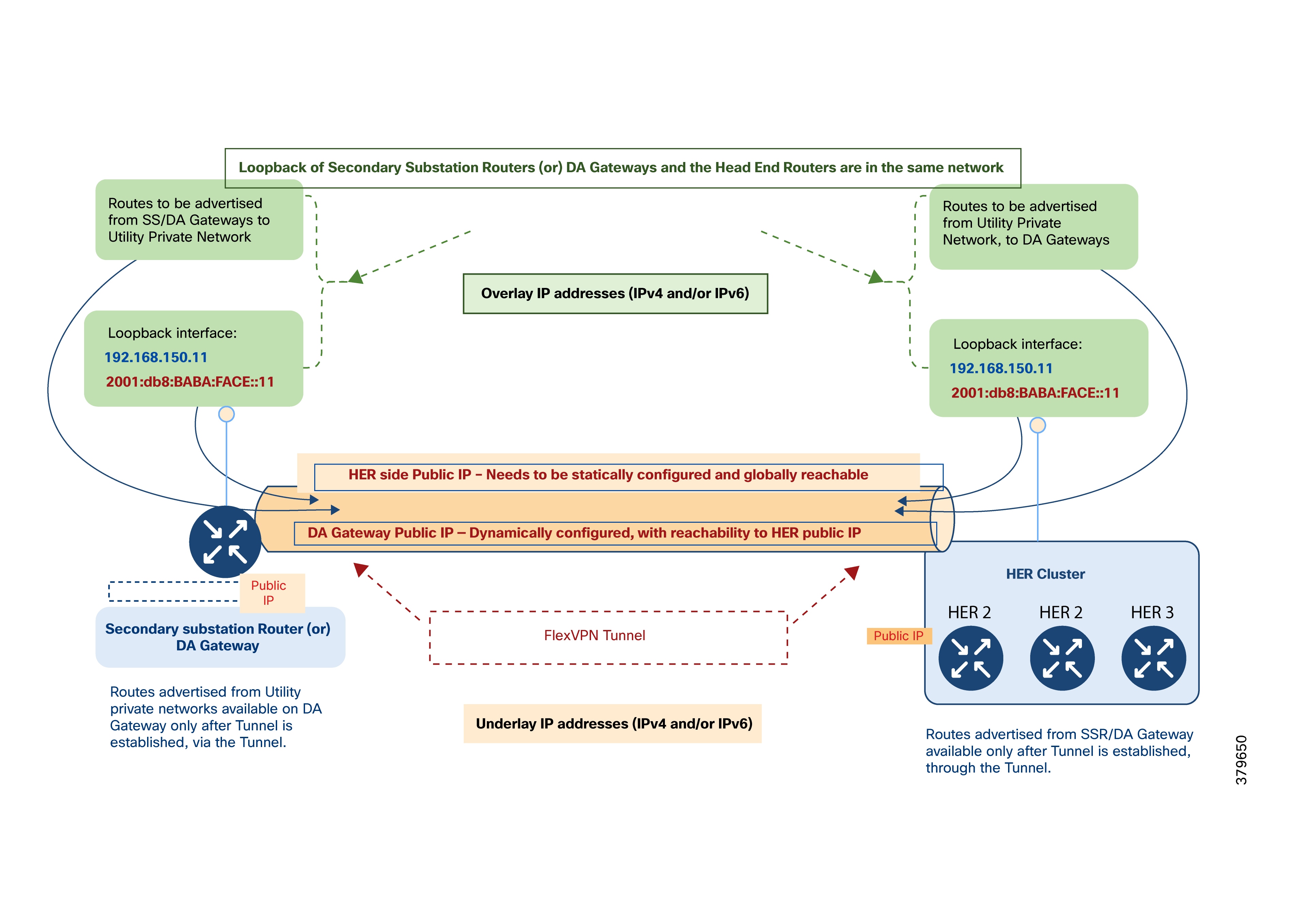
When the WAN IP address (underlay address) assigned to an IoT Gateway is dynamically allocated, it may change each time the device disconnects and reconnects. To ensure each IoT Gateway is uniquely identified regardless of WAN IP changes, an overlay IP address is assigned to the gateway’s loopback interface.
This overlay address, either IPv4 or IPv6, is allocated with a permanent lease from the DHCP server located in the communication headend of the Utility Private Network. Cisco IoT FND automatically handles this configuration during ZTD.
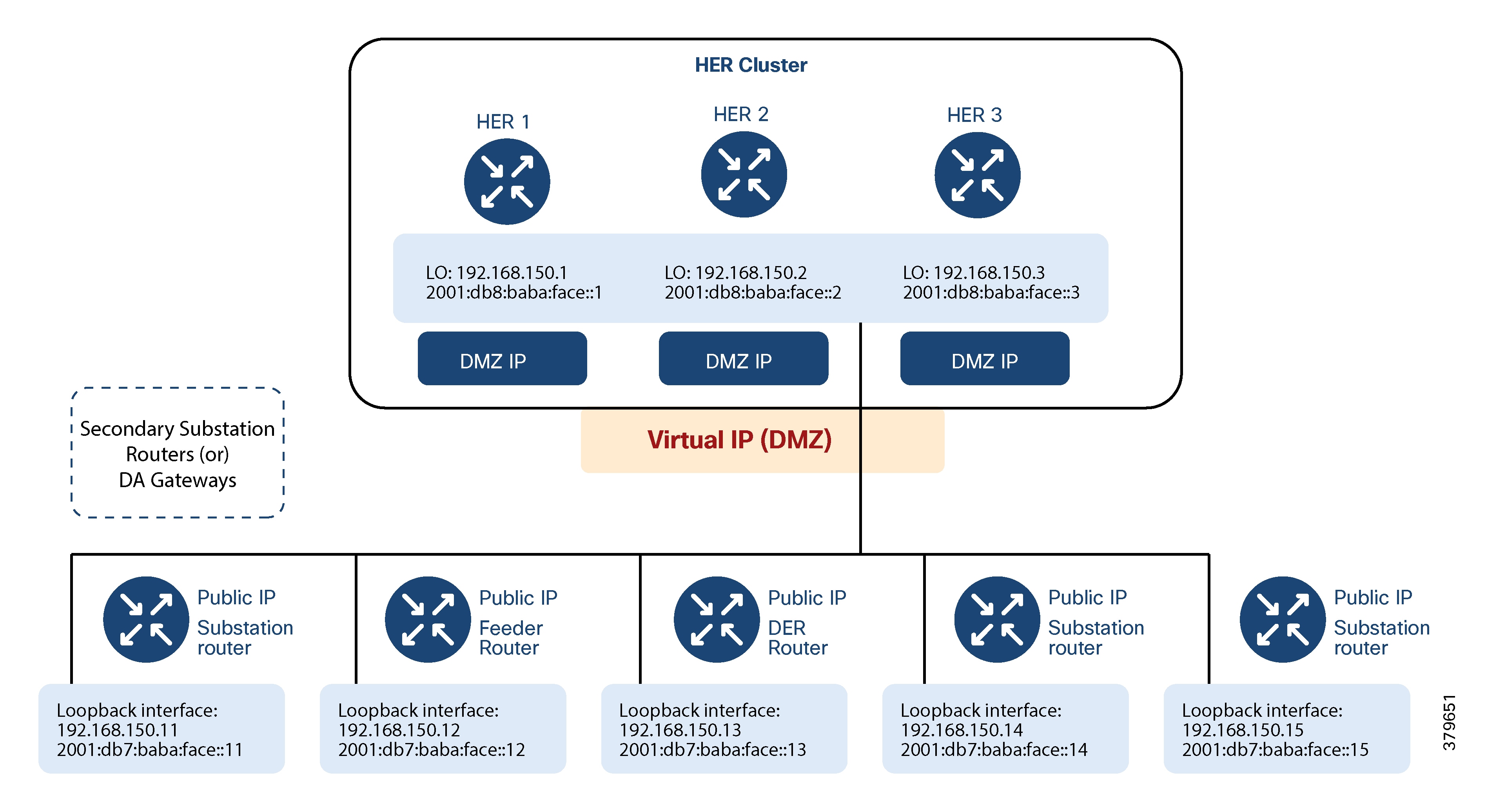
Since IoT Gateways are aggregated at the HER cluster, the overlay IP addresses assigned to their loopback interfaces are selected from the same IPv4 and IPv6 DHCP pools used by the HER loopback interfaces.
Although gateways and HERs share the same IPv4 and IPv6 subnets for loopback configuration, it is recommended to use a /32 subnet mask for IPv4 and a /128 mask for IPv6 addresses to ensure uniqueness.
Example:
If subnets 192.168.150.0/24 (IPv4) and 2001:db8:baba:face::/64 (IPv6) are used for SSRs and DA Gateways, respectively:
● Specific IP addresses within these subnets are reserved for HER loopback interfaces and are statically assigned, for instance:
◦ IPv4: 192.168.150.1, 192.168.150.2, 192.168.150.3
◦ IPv6: 2001:db8:baba:face::1, 2001:db8:baba:face::2, 2001:db8:baba:face::3
You must exclude these reserved addresses from the DHCP pool for SSRs and DA Gateways.
Note: Loopback addresses should be assigned with a permanent lease by the DHCP server. These addresses uniquely identify each DA Gateway to Cisco IoT FND, SCADA, and other application servers in the Utility Private Network.
Note: The tunnel aggregation point must always have a statically configured IP address.
The Utility Private Network corresponds to the headend block described in the network architecture. This protected segment contains:
● The private network portion of the communication headend
● The Utility Control Center
● The Utility PKI
Note: Note: All Utility Private Network components are part of the overlay network. Key systems include Cisco IoT FND, SCADA, DHCP Server, Certificate Authority, Active Directory, and AAA server.
Only the reachability information for select components, such as Cisco IoT FND and SCADA, needs to be advertised as overlay routes to IoT Gateways. Not all components need to be advertised.
This network layer interfaces with the Utility Public Network components like the Registration Authority (RA), Tunnel Provisioning Server (TPS), and HER cluster.
The following tables detail the components within the Private Network, Control Center, and PKI blocks, including their IP address configuration modes (static or dynamic), single/dual stack requirements, and whether they should be advertised as overlay routes to the IoT Gateway.
Table 7. Utility Private Network Part of Headend Communication
| Component name |
Mode of IP address configuration |
IPv4 / IPv6 / Dual-stack |
Should it be advertised to the IoT Gateway as an overlay route? |
| Cisco IoT FND |
Static IP address |
Dual-stack |
Yes |
| FND-Database |
Static IP address |
IPv4 is sufficient. However, IPv6 is also supported. |
No |
| DHCP Server |
Static IP address |
Dual-stack |
No |
| NTP |
Static IP address |
IPv4 |
No |
| DNS |
Static IP address |
Dual-stack |
No |
Table 8. Utility Control Center Part of Headend Communication
| Component name |
Mode of IP address configuration |
IPv4 / IPv6 / Dual-stack |
Should it be advertised to the IoT Gateway as an overlay route? |
| SCADA |
Static IP address |
Dual-stack |
Yes |
| Other Application Servers |
Static IP address |
Depends on what the control center application server supports |
Varies based on application requirements |
Table 9. Utility PKI Part of Headend Communication
| Component name |
Mode of IP address configuration |
IPv4 / IPv6 / Dual-stack |
Should it be advertised to the IoT Gateway as an overlay route? |
| Certificate Authority |
Static IP address |
IPv4 |
No |
| Active Directory |
Static IP address |
IPv4 |
No |
| AAA Server |
Static IP address |
IPv4 |
No |
Note: IoT Gateways obtain certificates using the RA, so routes for the Certificate Authority (CA) itself do not need to be advertised to the IoT Gateway.
The Utility Public Network consists of publicly-exposed network segments, usually positioned in the DMZ. This area manages communications from IoT Gateways in the Secondary Substation or Distribution Network.
The public network section includes:
● The DMZ portion of the communication headend, which houses:
◦ Registration Authority
◦ HER Cluster
◦ Tunnel Provisioning Server
Both SSRs and DA Gateways must have connectivity to the RA, TPS, and HERs.
The following figure shows the Utility Public Network (TPS, HER cluster, and RA) connecting southbound to the WAN (underlay), and northbound to the Utility Control Center, PKI, and private network headend.
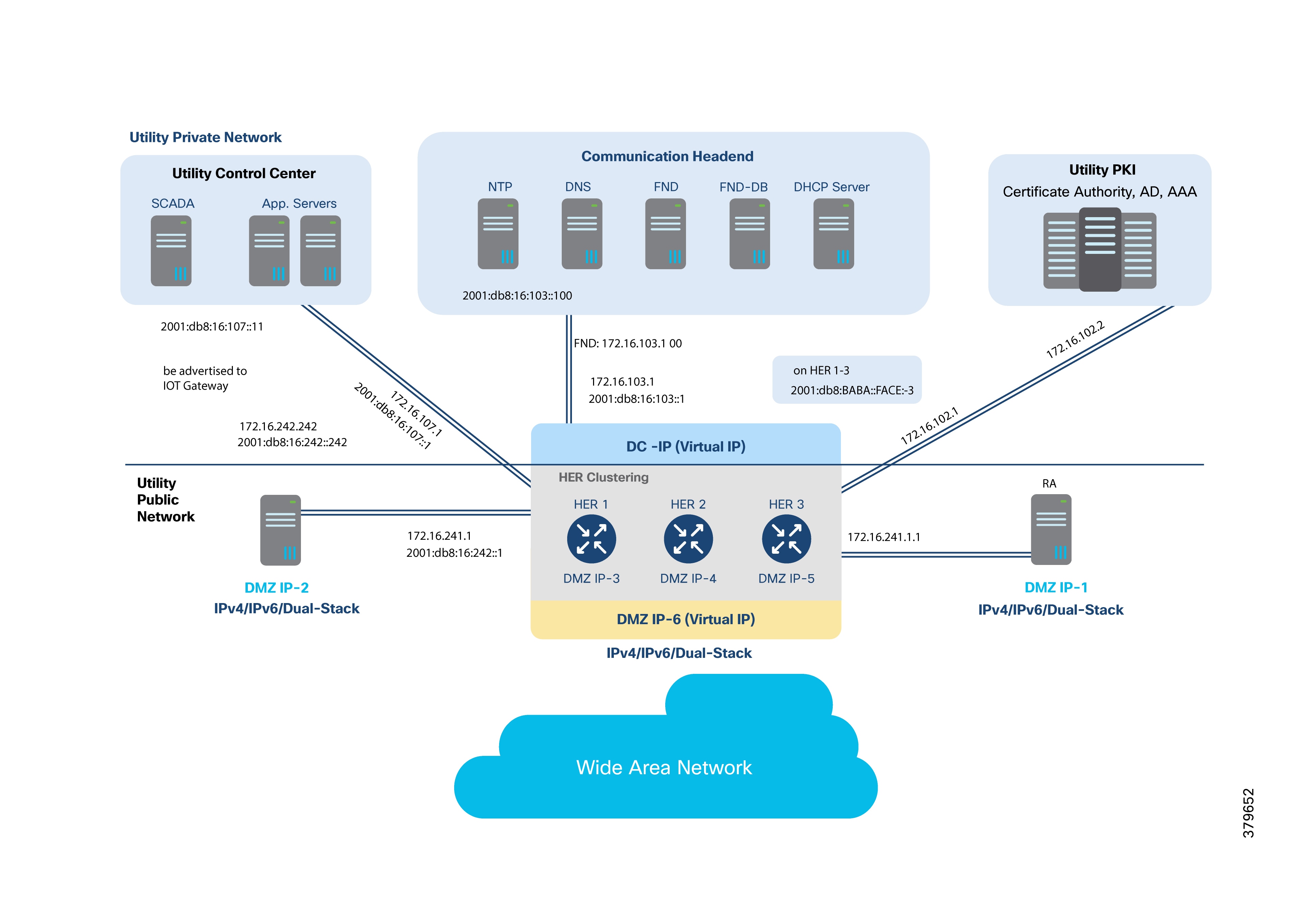
Note: Note: The HER cluster can serve as the default gateway for all Utility Private Network components, including the Control Center, PKI, and private network headend.
● DMZ IPs 1–6 are underlay public IP addresses and should be reachable from IoT Gateways.
● Once the FlexVPN Tunnel is established, the following overlay routes should be advertised:
◦ IPv4/IPv6 addresses of SCADA (control center)
◦ IPv4/IPv6 addresses of FND (communication headend)
◦ IPv4/IPv6 addresses of HER router loopbacks in the cluster
◦ Any other application server IPs that need to be advertised to IoT Gateways
◦ DHCP server IPs, if IoT Gateway needs to act as a DHCP relay
The following table lists the components in the Utility Public Network, their IP configuration modes, single/dual stack requirements, and whether they should be advertised as overlay routes.
Table 10. Utility public network’s configurations and overlay route advertisements
| Component name |
Mode of IP address configuration |
IPv4 / IPv6 / Dual-stack |
Should it be advertised to the IoT Gateway as an overlay route? |
| Registration Authority |
Static IP |
●
Northbound Network with CA: IPv4
●
Southbound Network facing WAN: Can be enabled for IPv4, IPv6, or dual-stack according to network capability and requirement.
|
N/A. It’s an underlay public IP. |
| Tunnel Provisioning Server |
Static IP |
●
Northbound Network with Cisco IoT FND: IPv4 may be sufficient. Dual-stack is recommended.
●
Southbound Network facing WAN: Can be enabled for IPv4, IPv6, or dual-stack according to network capability and requirement.
|
N/A. It’s an underlay public IP. |
| HER Cluster |
Static IP |
Northbound Network with Utility Control Center (hosting SCADA, and other application servers):
● Dual-Stack is recommended.
|
Yes, SCADA Master needs to be advertised. |
|
|
|
Northbound Network with Utility PKI:
● IPv4
|
No. |
|
|
|
Northbound Network with Utility Private Communication Headend:
● Dual-Stack is recommended.
|
Yes, FND needs to be advertised. |
|
|
|
East West Networks with Registration Authority:
● IPv4
|
No. |
|
|
|
East West Networks with Tunnel Provisioning Server:
● IPv4 may be sufficient. Dual-Stack is recommended.
|
No. |
|
|
|
Southbound Networks facing WAN:
● Can be enabled for IPv4, IPv6, or dual-stack according to WAN (underlay) network capability.
|
N/A. It’s an underlay public IP. |
|
|
|
Loopback Interface representing HER:
● Dual-Stack recommended.
|
Yes. Both IPv4 and IPv6 addresses must be advertised. |
DA Cellular uses the WAN to connect the headend block with substations or DA sites. The WAN acts as the underlay network and supports IPv4-only, IPv6-only, or dual-stack deployments.
IP addressing for SSRs is similar to that for DA Gateways. The primary difference is if a utility requires the SSR to aggregate communications from multiple DA Gateways, rather than connecting each gateway directly to the DSO headend.
Note: If SSRs aggregate tunnels from multiple DA Gateways, it is recommended to use static WAN IP addresses for the SSRs.
The following figure demonstrates that the SSR can serve RTUs, IPv4 IEDs, and IPv6 IEDs.
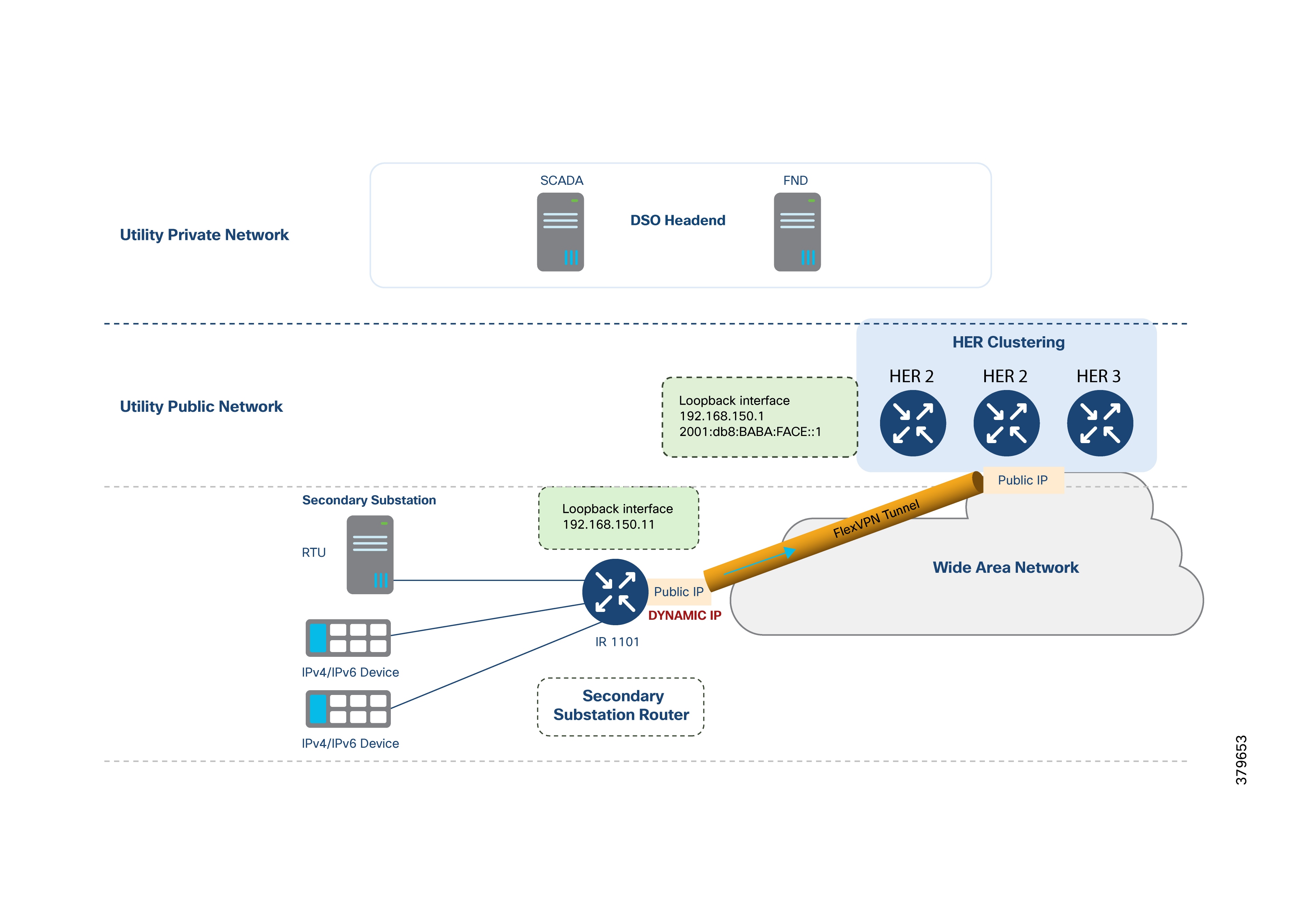
The WAN IP address can be dynamically allocated and may change upon reconnection; the SSR is uniquely represented by its IPv4 and IPv6 loopback addresses, which are configured by Cisco IoT FND during ZTD. Static WAN IPs are also fully supported.
IPv4 and IPv6 devices at the substation can be advertised to the DSO headend using their configured IPs, or their addresses can be translated (using NAT) to the SSR IP to keep routing simple and consistent (see the Network Address Translation section).
Legacy devices with serial interfaces can communicate with the DSO headend using raw sockets or protocol translation services provided by the SSR.
Table 11. IP addresses on SSR – Dynamic WAN IP scenario
| Component name |
Mode of IP address configuration |
IPv4 / IPv6 / Dual-stack |
Should it be advertised to the IoT Gateway as an overlay route? |
| WAN IP |
Dynamically allocated IP address |
Could be IPv4-only, IPv6-only, or dual-stack |
N/A. It's an underlay IP. |
| Loopback IP |
Dynamically configured by Cisco IoT FND during ZTD |
Dual-stack recommended |
Yes |
| Addresses of the IPv4 and IPv6 IEDs |
SSR can allocate IP addresses to the IEDs through DHCP, if IED is DHCP-capable |
Could be IPv4-only, IPv6-only, or dual-stack |
Not required if IED IP addresses are translated to the SSR's IP address. |
The following figure shows DA Gateways being aggregated at the SSR. In this scenario, the SSR must have a static public IP address to terminate tunnels from the DA Gateways. Loopback addressing and access to IEDs are configured similarly as described above.
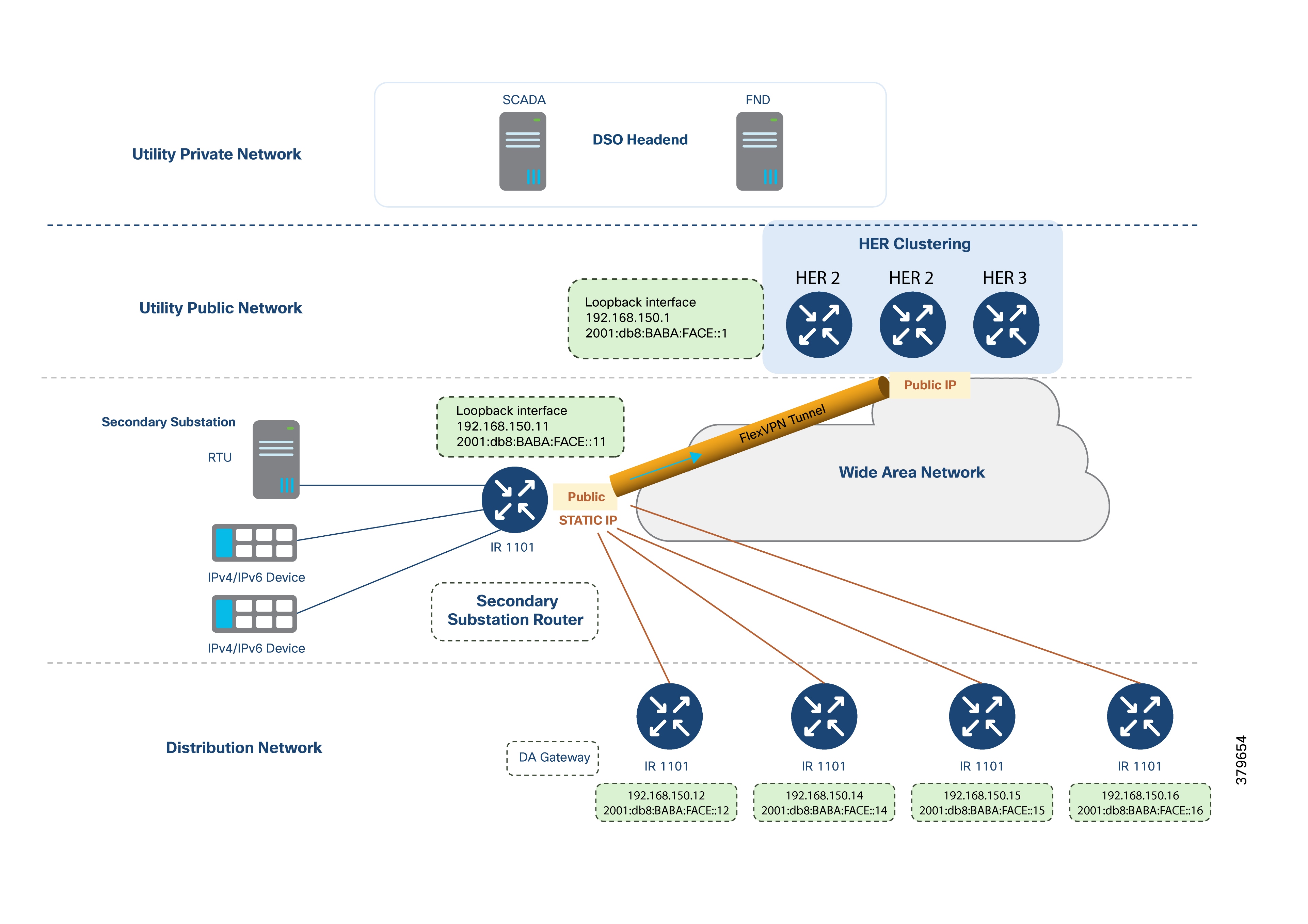
In addition to advertising the routes to the DSO headend, the SSR could choose to selectively advertise a subset of the routes in the southbound direction to the DA Gateways.
Table 12. IP addresses on SSR – static WAN IP scenario
| Component name |
Mode of IP address configuration |
IPv4 / IPv6 / Dual-stack |
Should it be advertised to the IoT Gateway as an overlay route? |
| WAN IP |
Dynamically allocated IP address |
Could be IPv4-only, IPv6-only, or dual-stack |
N/A. It's an underlay IP. |
| Loopback IP |
Dynamically configured by Cisco IoT FND during ZTD |
Dual-stack recommended |
Yes |
| Addresses of the IPv4 and IPv6 IEDs |
Static and DHCP are supported |
Could be IPv4-only, IPv6-only, or dual-stack |
Not required if IED IP addresses are translated to the SSR's IP address. |
DA Gateways deployed in the field receive their WAN IP addresses (IPv4, IPv6, or both) dynamically from the service provider. These addresses serve as underlay IPs and are used to establish the FlexVPN tunnel.
The following figure shows how a DA Gateway can serve IPv4 IEDs, IPv6 IEDs, and serial devices, facilitating overlay communication with DSO headend components such as Cisco IoT FND and SCADA.
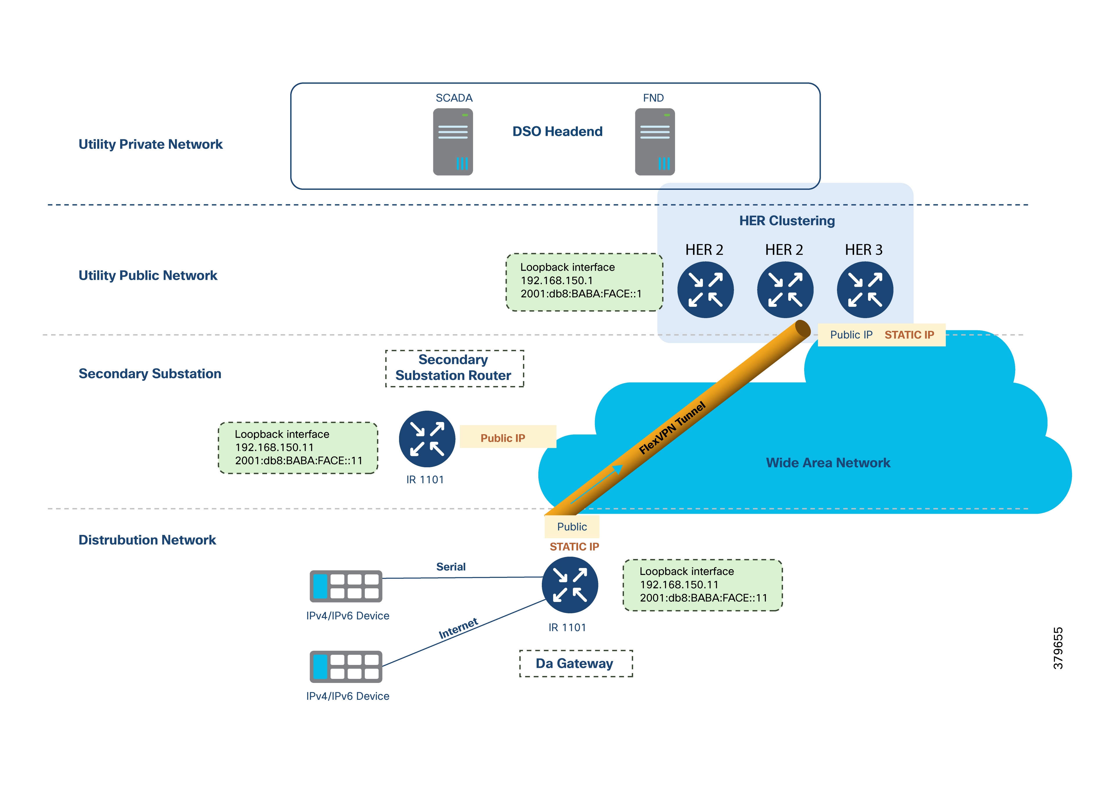
IPv4 and IPv6 IEDs may be advertised to the DSO headend using their configured IP addresses, or, for consistency and simplicity in routing, their addresses may be translated to the DA Gateway’s IP address. Further details are provided in the Network Address Translation section.
Each DA Gateway is uniquely identified by its IPv4 and IPv6 loopback addresses, which are configured by Cisco IoT FND as part of the ZTD process.
Figure 31 also illustrates a FlexVPN tunnel established between the DA Gateway and the HER Cluster at the DSO headend. If the utility requires aggregation of multiple DA Gateways at the substation, the DA Gateway can establish an additional tunnel to the SSR.
Table 13. IP addresses on DA gateway – dynamic WAN IP scenario
| Component name |
Mode of IP address configuration |
IPv4 / IPv6 / Dual-stack |
Should it be advertised to the IoT Gateway as an overlay route? |
| WAN IP |
Dynamically allocated IP address |
Could be IPv4-only, IPv6-only, or dual-stack |
N/A. It's an underlay IP. |
| Loopback IP |
Dynamically configured by Cisco IoT FND during ZTD |
Dual-stack recommended |
Yes |
| Addresses of the IPv4 and IPv6 IEDs |
Static and DHCP are supported |
Could be IPv4-only, IPv6-only, or dual-stack |
Not required if IED IP addresses are translated to the SSR's IP address. |
Summary of IP Address Allocation Methods
Table 16 summarizes the different IP addressing components, their respective locations, and allocation methods:
Table 14. Address allocation methods for components
| Components category |
Location |
IP Assignment Type |
Sample subnet or IP description |
| Components in Data Center or Control Center, including CA, SCADA, NMS, and more |
Utility Private Network (Trusted Area) |
Static IP address |
Utility Control Center: 172.16.107.0/24 2001:db8:16:107::/64 Communication Private Network:
● 172.16.103.0/24
● 2001:db8:16:103::/64
Utility PKI Network: 172.16.102.0/24 |
| Components in public part of the headend, such as RA, TPS, HER1, HER2, and HER3 |
Utility Public Network (DMZ Area) |
Static IP address |
DMZ IP-X (IPv4 and/or IPv6) |
| IoT Gateways positioned as SSR, aggregating multiple DA Gateways. |
Secondary Substation |
Static IP address |
Public WAN IP statically configured. Should be reachable from DA Gateways across the Distribution Network. |
| IoT Gateways positioned as SSR, not aggregating any DA Gateways |
Secondary Substation |
Dynamically allocated |
Public WAN IP allocated dynamically by service provider over Cellular or Ethernet networks. |
| IoT Gateways positioned as DA Gateways |
Across Distribution network |
Dynamically allocated |
Public WAN IP dynamically allocated by service provider over Cellular or Ethernet networks. |
Loopback addresses for HER1, HER2, and HER3 are configured manually once on the Utility Public Network.
Loopback addresses for SSRs and DA Gateways are dynamically assigned by Cisco IoT FND during ZTD, using DHCP (IPv4 and IPv6) pools from which HER loopback addresses are drawn.
The WAN tier connects the field area and the Secondary Substation to the control center. When designing the WAN backhaul and its routing protocols, consider:
● Scalability: WAN must support aggregation routers at the control center and SSRs/DA Gateways in the field, and should be capable of handling many IP tunnels, including dual tunnel configurations for resilience.
● Redundancy and High Availability: Design should meet SLAs for uptime.
● Routing Protocols: Cisco IOS supports dual-stack routing protocols such as MP-BGP, OSPFv3, RIPv2/RIPng, EIGRP, static routes, and IKEv2 prefix injection from FlexVPN.
● Existing Infrastructure: Leverage current WAN infrastructure connecting to control centers.
● Topology: Consider hub-and-spoke configurations.
● Static vs. Dynamic Routing: Choose based on operational needs.
● Ease of Configuration: Simplicity is key for maintenance and scalability.
● Convergence Time: Minimize downtime when losing connectivity with HER or SSR.
● Latency and Bandwidth: Design for optimal performance given traffic flow patterns.
● Control Traffic Minimization: Reduce unnecessary control traffic over the WAN.
Refer to the Security, High Availability & Scale section for a detailed discussion of WAN backhaul redundancy.
Cellular backhaul is the primary deployment model, and Cisco IR1101 is recommended for use as both SSR and DA Gateway. Cisco IR1101 supports two 4G LTE modules for cellular backhaul with redundancy.
For more details about other supported TDD LTE, UMTS, HSPA+ and HSPA bands, see the Cisco Catalyst IR1101 Rugged Series Router Data Sheet.
Key features of Cisco IR1101 LTE modules include:
● Dual SIM in a single radio, allowing seamless failover if one SIM loses connectivity.
● Dual SIM, dual radio configuration for additional redundancy, where the primary SIM is inserted in the LTE module of the Cisco IR1101 base unit and the secondary SIM is placed in the Cisco IR1101 expansion module.
● Auto SIM mode for automatic carrier selection and modem reset upon SIM switch.
● Assisted GPS (A-GPS) for location services.
● SMS support
● Modem firmware upgrades
● SIM lock/unlock capabilities
● IPv6 protocol support on cellular interfaces
When Distribution Automation (DA) traffic traverses a public WAN, all data should be encrypted using standards-based IPSec, even if the backhaul is private. Site-to-site IPSec VPNs can be established between DA Gateways or SSRs and the HER at the control center.
Cisco’s Distribution Automation solution uses advanced key generation and exchange mechanisms for both link layer and network layer encryptions, simplifying key management and supporting scalability across thousands of devices.
IP tunnels are a key capability for all DA use cases, forwarding various traffic types over the backhaul WAN infrastructure. It is important to evaluate each tunneling technique by OS support, performance, and scalability for the DA Gateway, SSR, and HER platforms.
Tunneling Considerations:
● IPSec Tunnel: Secures all traffic over untrusted WAN. IPSec GRE tunnels can be established over IPv4-only, IPv6-only, or dual-stack WANs.
● GRE Tunnel: Communications with IPv6 IEDs can be sent securely as overlay traffic through an IPv4 or IPv6 GRE tunnels secured with IPSec.
In the following figure, the underlay IPSec tunnel can be established over any supported WAN infrastructure, securely carrying both IPv4 and IPv6 IED communications.
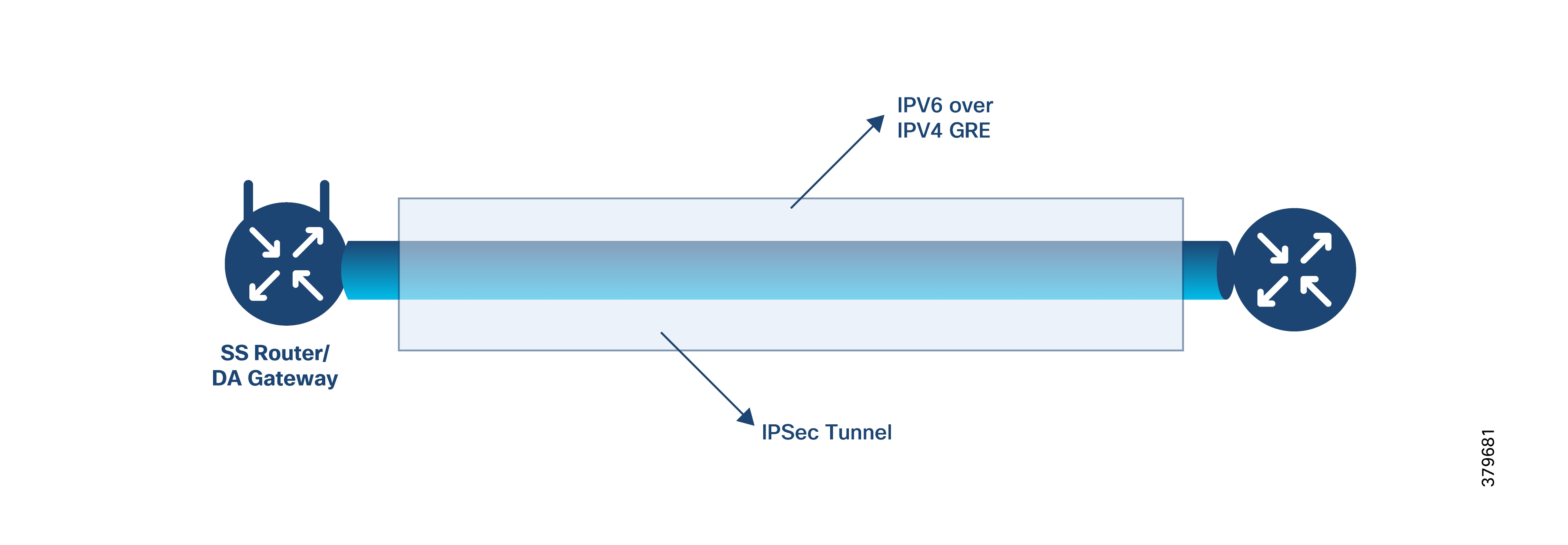
FlexVPN is a flexible, scalable VPN solution based on IPSec and IKEv2. It is recommended for securing DA data communication with the headend across the WAN. Cisco IoT FND automates FlexVPN tunnel establishment between HERs and DA Gateways during ZTD.
Key benefits of FlexVPN:
● Supports both IPv4 and IPv6 within a single tunnel when supported by the medium.
● Supports NAT/PAT traversal.
● Supports bidirectional QoS (hub-to-spoke and spoke-to-hub).
● Supports Virtual Routing and Forwarding (VRF).
● Reduces control plane traffic, ideal for costly links. This solution uses the IPSec tunnel mode.
● IKEv2 enables faster negotiation (two round trips vs. five for IKEv1), and uses ports 500 and 4500 for NAT-T.
● Built-in Dead Peer Detection (DPD), configuration payload, user authentication, and NAT traversal.
● Improved re-keying and collision handling.
● Single Security Association (SA) can protect multiple subnets; supports Multi-SA Dynamic Virtual Tunnel Interfaces (DVTI) at the hub.
● Asymmetric authentication in site-to-site VPNs, where there are differences in the use of pre-shared keys and certificates for authentication.
In the FlexVPN model, the HER acts as the hub, and DA Gateways act as spokes. Tunnel interfaces on DA Gateways receive addresses from pools configured during ZTD, with local significance between HER and DA Gateways.
The NMS addresses DA Gateways via their loopback interfaces, and DA Gateways source traffic from their loopbacks.
Before tunnel establishment, DA Gateways can only communicate with HER over the WAN using a default route. During FlexVPN handshake, HER and DA Gateway exchange route information, allowing DA Gateways to learn headend routes (IPv4 and IPv6) through FlexVPN.’
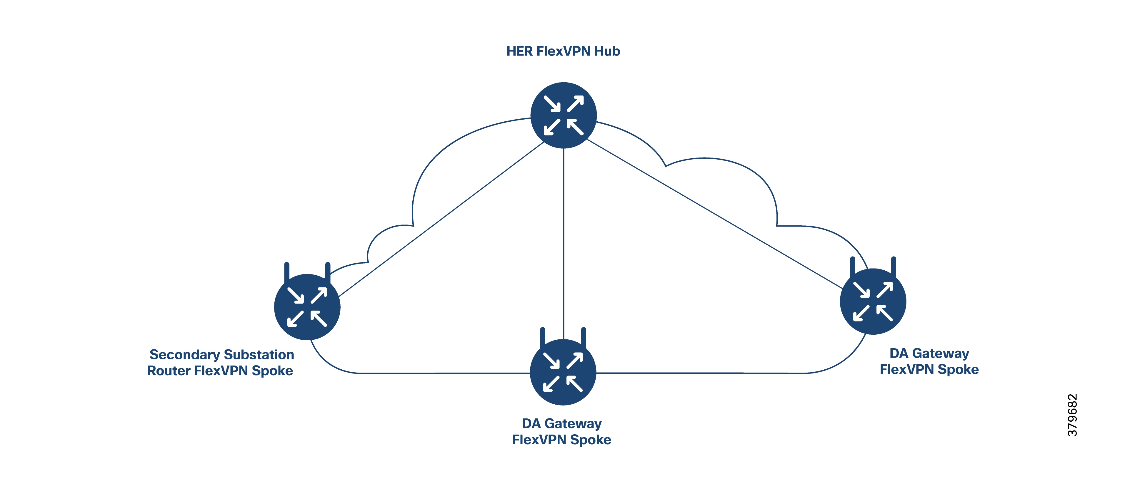
FlexVPN is preferred over DMVPN when WAN link costs are volume-based. Key reasons include:
● No need for dynamic routing; IKEv2 prefix injection is supported for both IPv4 and IPv6.
● IPv6 is supported natively, reducing control plane traffic compared to DMVPN. Dynamic routing is essential in DMVPN. In FlexVPN, prefixes are only injected for tunnel establishment.
● No Next Hop Resolution Protocol (NHRP) is required, further reducing control plane traffic.
● QoS can be customized per channel, unlike DMVPN where QoS rules are applied to all downstream channels.
● NAT/PAT can be set on both sides of hub and spoke.
● Flexible hub clustering options for redundancy.
● IKEv2 supports snapshot-based routing, beneficial for mesh networks.
● IKEv2 tunnels allow switching tunnels across interfaces.
For cellular connections, if the service provider imposes data limits, FlexVPN’s minimal control plane traffic is advantageous. With FlexVPN, prefix-based injection and snapshot-based routing minimize unnecessary data usage, reducing overhead compared to DMVPN.
If no data limit exists, DMVPN can also be considered, but FlexVPN is generally preferred for its efficiency.
For most deployments (especially in Europe) cellular backhaul is primary. FlexVPN with IKEv2-based prefix injection is the recommended approach for IP routing, significantly reducing monthly control traffic (by approximately 100 MB or more), thereby maximizing available bandwidth for application data.
This routing approach lowers total cost of ownership (TCO). Once the tunnel is provisioned between a DA Gateway or SSR and the HER via Zero Touch Deployment, IED prefixes from the field area or Secondary Substation are advertised to HER, and SCADA prefixes are advertised to DA Gateways or SSRs after tunnel establishment.
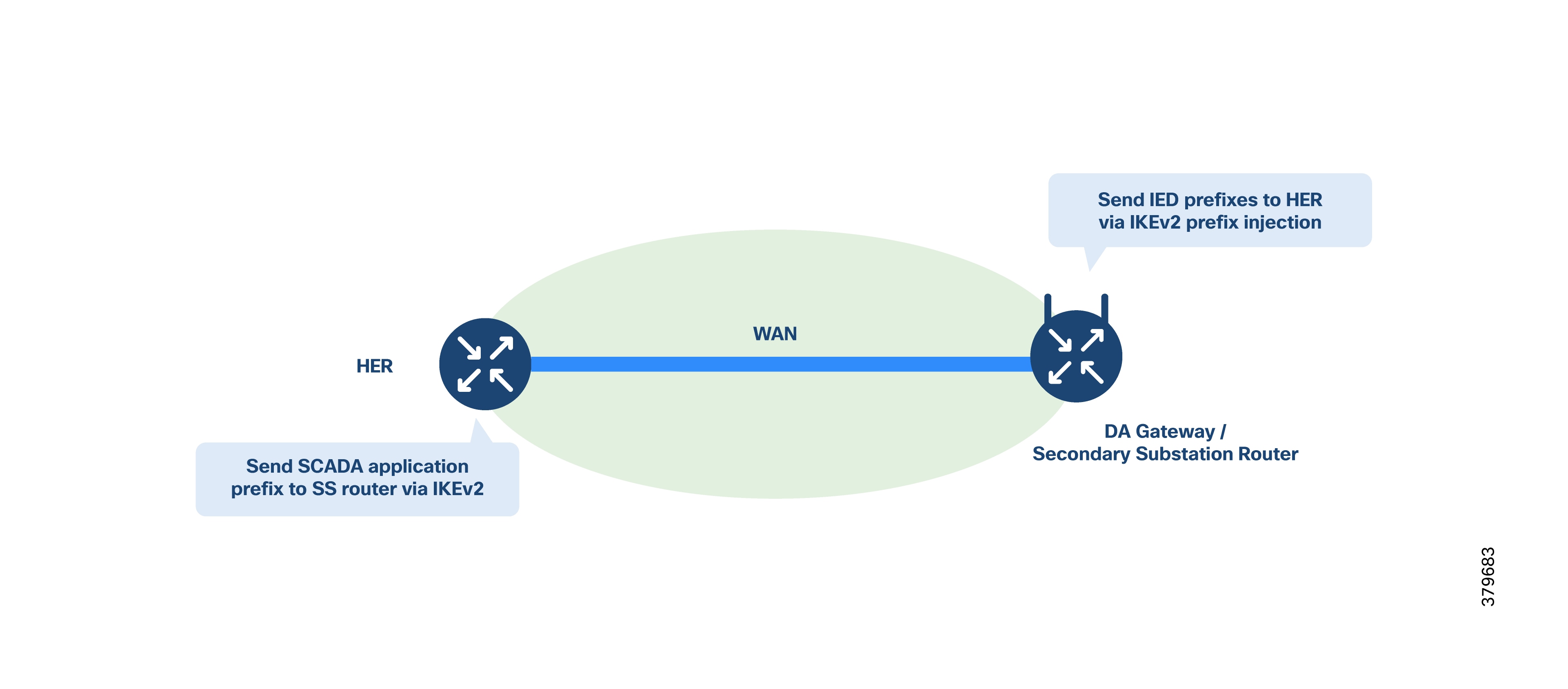
To ensure proper substation operation, utilities use SCADA systems to automate monitoring and control. New sites typically implement SCADA for real-time supervision.
Existing sites must consider adoption of SCADA or updating current SCADA systems, as may be applicable, to benefit from upgrades to modern systems. Enhanced SCADA solutions improve equipment lifespan, enable proactive maintenance, and reduce costs by providing both live and historical data.
Three SCADA service models are supported, as shown in Table 17.
Table 15. SCADA service models
| Service |
Connectivity |
Service model |
| Legacy SCADA (DNP3, Modbus, T101) |
Point-to-Point (primary, secondary) |
Raw socket over FlexVPN |
| Legacy SCADA (DNP3, Modbus, T101) |
P2MP multi-drop |
Raw socket over FlexVPN |
| SCADA Gateway (DNP3, T101) to IP Conversion (DN3-IP, T104) |
Point-to-Point (primary, secondary) |
Protocol translation over FlexVPN |
| SCADA Gateway (DNP3, T101) to IP Conversion (DN3-IP, T104) |
Multi-primary |
Protocol translation over FlexVPN |
| SCADA (DNP3-IP, Modbus-TCP, T104) |
Point-to-Point (primary, secondary) |
FlexVPN |
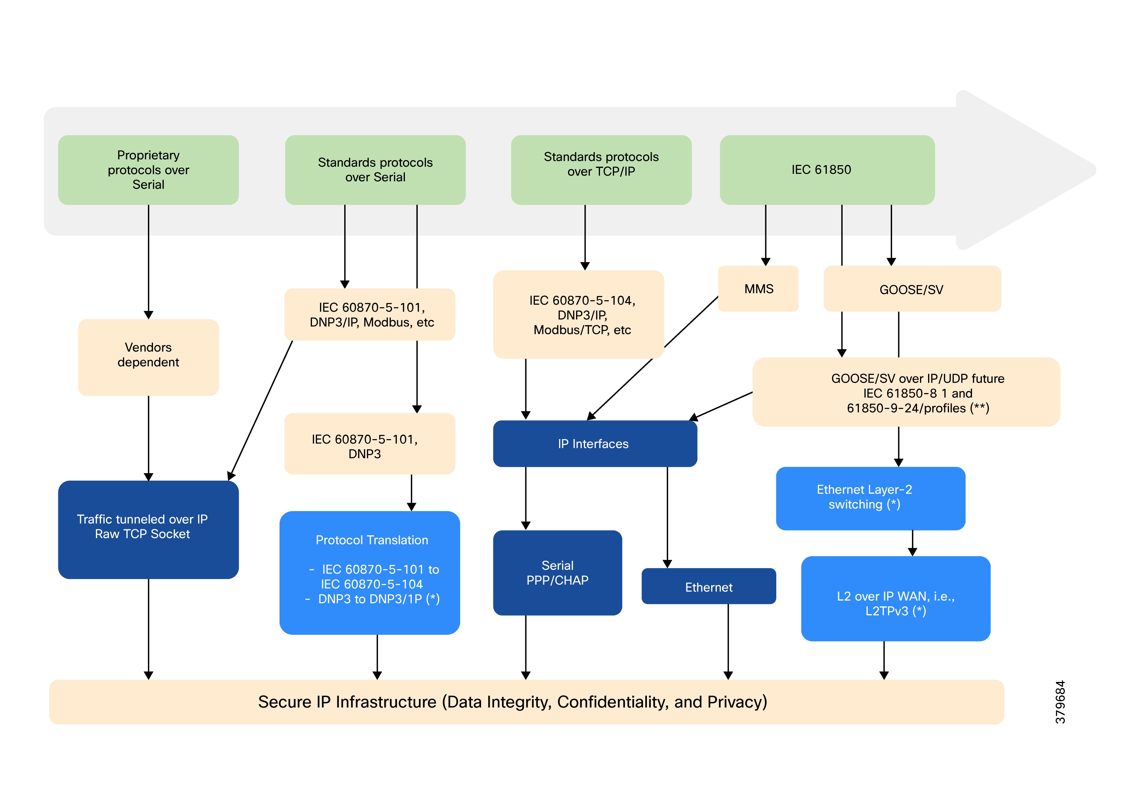
The above figure displays multiple technologies for SCADA traffic transport. Standard IP routing can be used for IEC 60870-5-104, DNP3 IP, and Modbus application traffic between IEDs in substations or feeders and the DSO Control Center.
SCADA Components and Protocols
Managing electrical distribution involves many remote applications and sites. RTUs and IEDs have been introduced to address this complexity and are typically part of most substations today.
Remote Terminal Units (RTUs)
RTUs provide intelligent I/O collection and processing, converting data from field devices into a SCADA-compatible format, and translating SCADA outputs into appropriate signals that field equipment can understand.
Intelligent Electronic Devices (IEDs)
IEDs are widely deployed in substations and typically communicate with the RTU.
Control Center
The SCADA system includes a primary control station with one or more PC-based human-machine interfaces (HMIs), and possibly secondary stations or local HMIs at large substations. Operators use HMIs to monitor and control operations, leveraging SCADA’s ability to process large volumes of electrical state data.
SCADA Protocols
Protocols relevant for Utilities:
● Legacy protocols (asynchronous interfaces): Modbus, DNP3, IEC 60870-5-101
● Ethernet protocols (IP-based): Modbus-IP, DNP3-IP, IEC 60870-5-104, IEC 61850 MMS
● Layer 2 protocols: IEC 61850 GOOSE, IEC 61850 SV
Raw sockets provide a means to transport character streams from one serial asynchronous interface to another over the IP network. Utilities have used serial communication (over RS232, RS485) for decades; migrating to Ethernet requires hybrid support for both serial and Ethernet devices.
Raw sockets transport SCADA data from RTUs, supporting point-to-point and point-to-multipoint connections.
Packetization of serial data is based on specific lengths, characters, or timers, with auto TCP connection retry mechanisms. Sub-options allow users to customize packetization for deployment needs.
SCADA data is routed from substation to control center with latency ranging from ~500 ms to ~5 seconds.
This uses a client-server model (one server, multiple clients per serial line). The client receives serial data from RTUs, buffers and packetizes it, then initiates a TCP connection to the server and transmits the data. The server extracts and forwards the data to the appropriate serial interface.
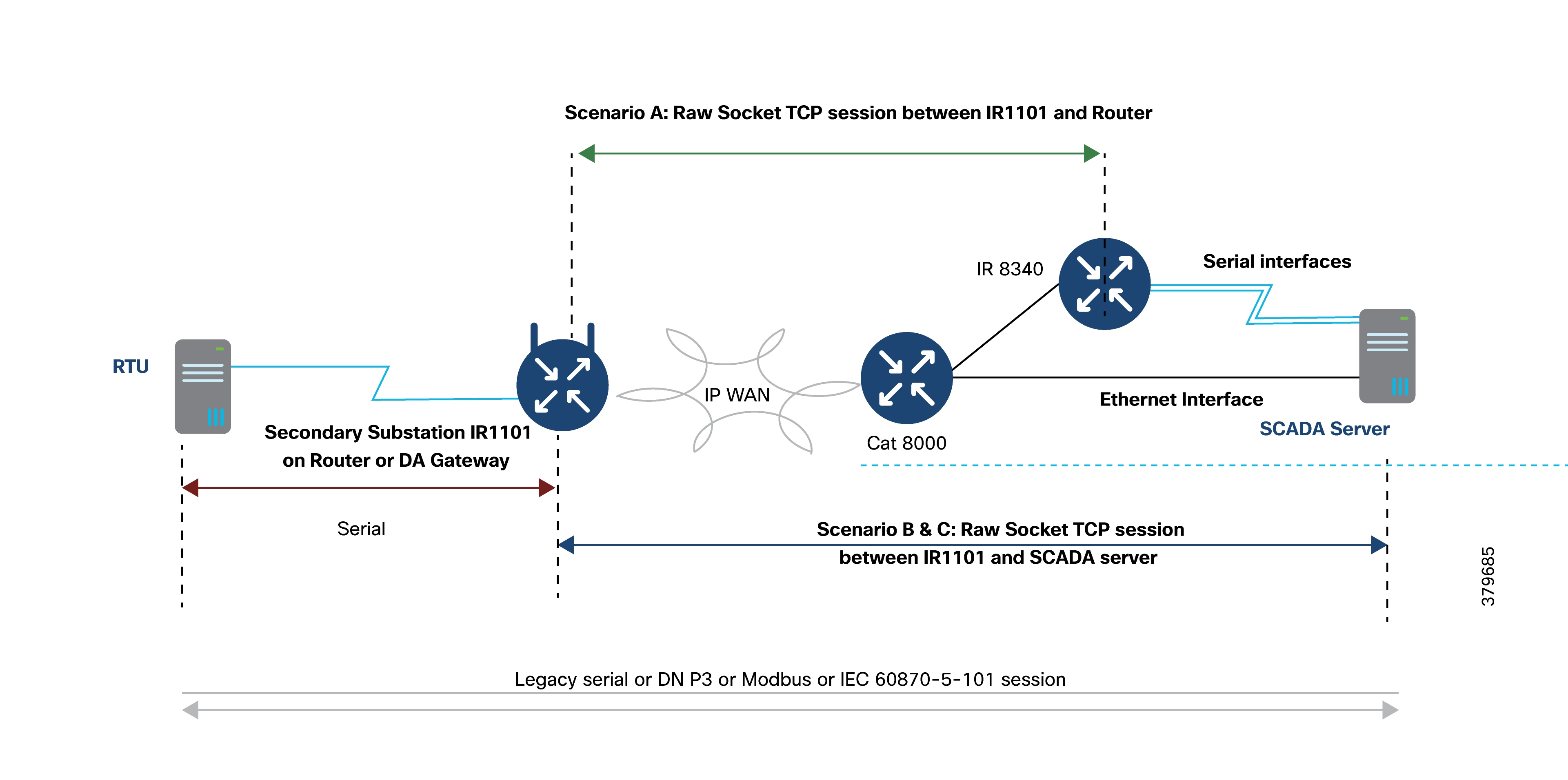
Deployment Scenarios:
● Scenario A: Raw socket between SSRs or DA Gateways and SCADA Router at the headend. There is no change one the SCADA server, and communications use COM ports.
● Scenario B: Raw socket between Cisco IR1101 and SCADA Server. No server application changes areneeded, but IP/Serial Redirector software maps COM port to IPv4 address and TCP port, using Ethernet.
● Scenario C: Raw socket between Cisco IR1101 and SCADA Server. The SCADA application communicates directly over a raw socket (IPv4 address and TCP port) using Ethernet.
Note: Scenario A is not scalable; Scenario B and Scenario C are highly recommended for raw socket deployments.
UDP transport operates in a peer-to-peer model, allowing multiple UDP connections to be configured on a single asynchronous serial line.
The raw socket UDP peer collects streams of serial data from RTUs, buffers the data, and packetizes it according to user-defined criteria.
The packetized data is then transmitted across the IP network to a corresponding raw socket peer at the remote end, which extracts the serial data from the packets and forwards it to the serial interface for delivery to the utility management system.
Raw Socket Dual Control Center Multi-Drop Bridging
A raw socket on a DA Gateway or SSR can replicate its packets to multiple control centers. As shown in the following figure, two geographically separated DSO control centers (primary and secondary) can each host SCADA applications. DA Gateways are configured as TCP raw socket clients, each maintaining separate sockets for each control center.
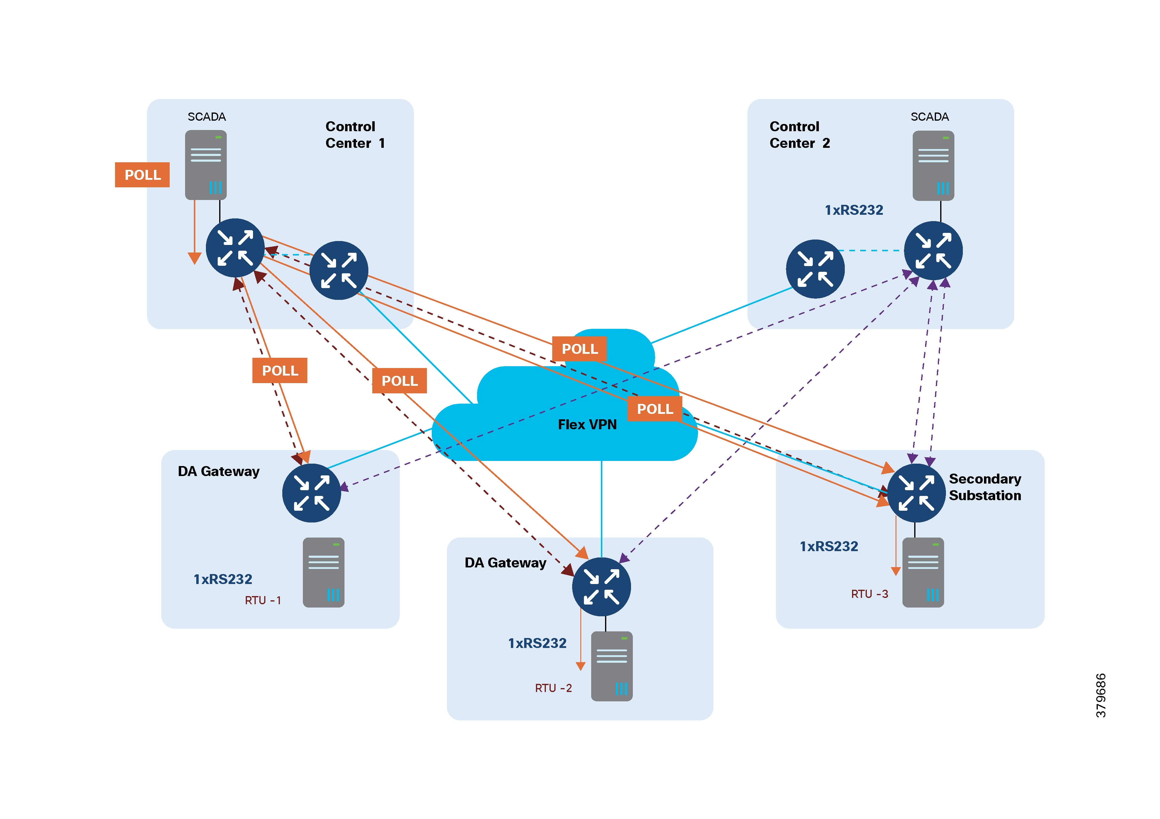
IP routing is essential for establishing sockets across control centers, supporting disaster recovery and application-level redundancy. The SCADA server at each control center periodically polls RTUs, addressing each poll to a specific RTU. The HER replicates application traffic to raw socket destinations as required.
Only the RTU addressed by the SCADA application responds to the poll, and its reply is replicated to all SCADA destinations.
It is important that the SCADA reply from the RTU is not fragmented. As shown in the following figure, to prevent fragmentation at the TCP layer, the client can be configured with options such as special characters, packet length, and packet timer to ensure replies are correctly packed into single TCP packets.
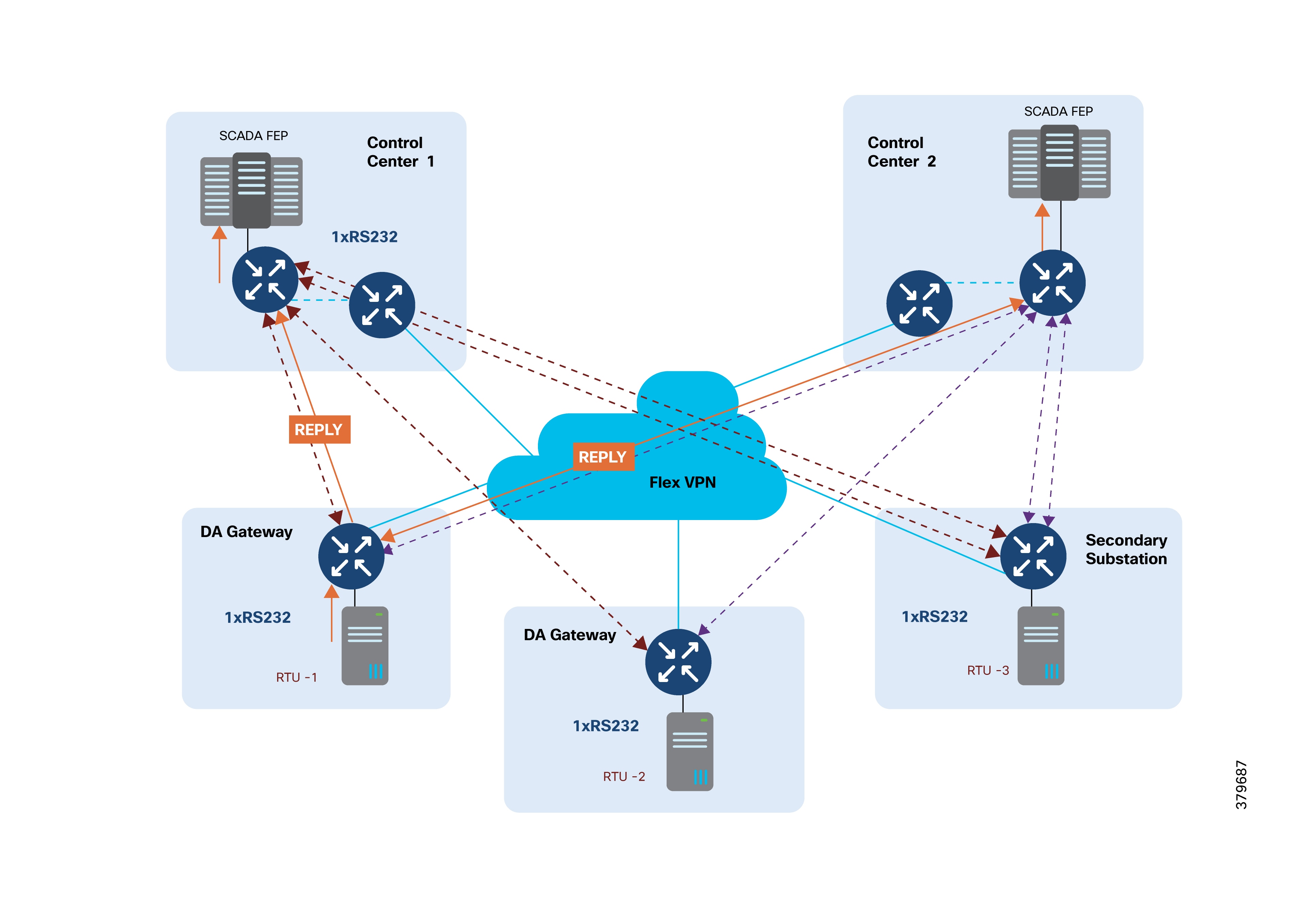
From the control center, both SCADA application polling and device control operations can be performed simultaneously. If an RTU needs to send unsolicited reports, raw sockets replicate this application traffic to both control centers.
As utilities transition from legacy SCADA protocols to IP-based protocols, an effective migration strategy is required to allow both protocol types to operate together. The protocol translation feature—also known as the SCADA Gateway function on the IR1101—enables this interoperability.
Cisco IOS supports protocol translation between:
● IEC 60870-5-101 and IEC 60870-5-104
● DNP3 Serial and DNP3 IP
Additional protocol translation capabilities can be implemented using IOx applications, leveraging the platform’s Edge Compute features.
The following software stacks are implemented on Cisco SSRs and DA Gateways:
● IEC-101 and DNP3 Serial Protocol Stack
● IEC-104 and DNP3 IP Protocol Stack
● Translation module supporting:
◦ IEC-101 to IEC-104
◦ DNP3 Serial to DNP3 IP
As depicted in the following figure, Cisco IR1101 can be deployed as a SCADA Gateway, supporting both T101 primary and T104 secondary functionalities. Each RTU is connected via a dedicated serial interface. The DA Gateway or SSR serves as the T101 primary for the T101 secondary RTU, and acts as the T104 secondary to the SCADA T104 primary located at the control center. This setup illustrates a point-to-point protocol translation scenario.
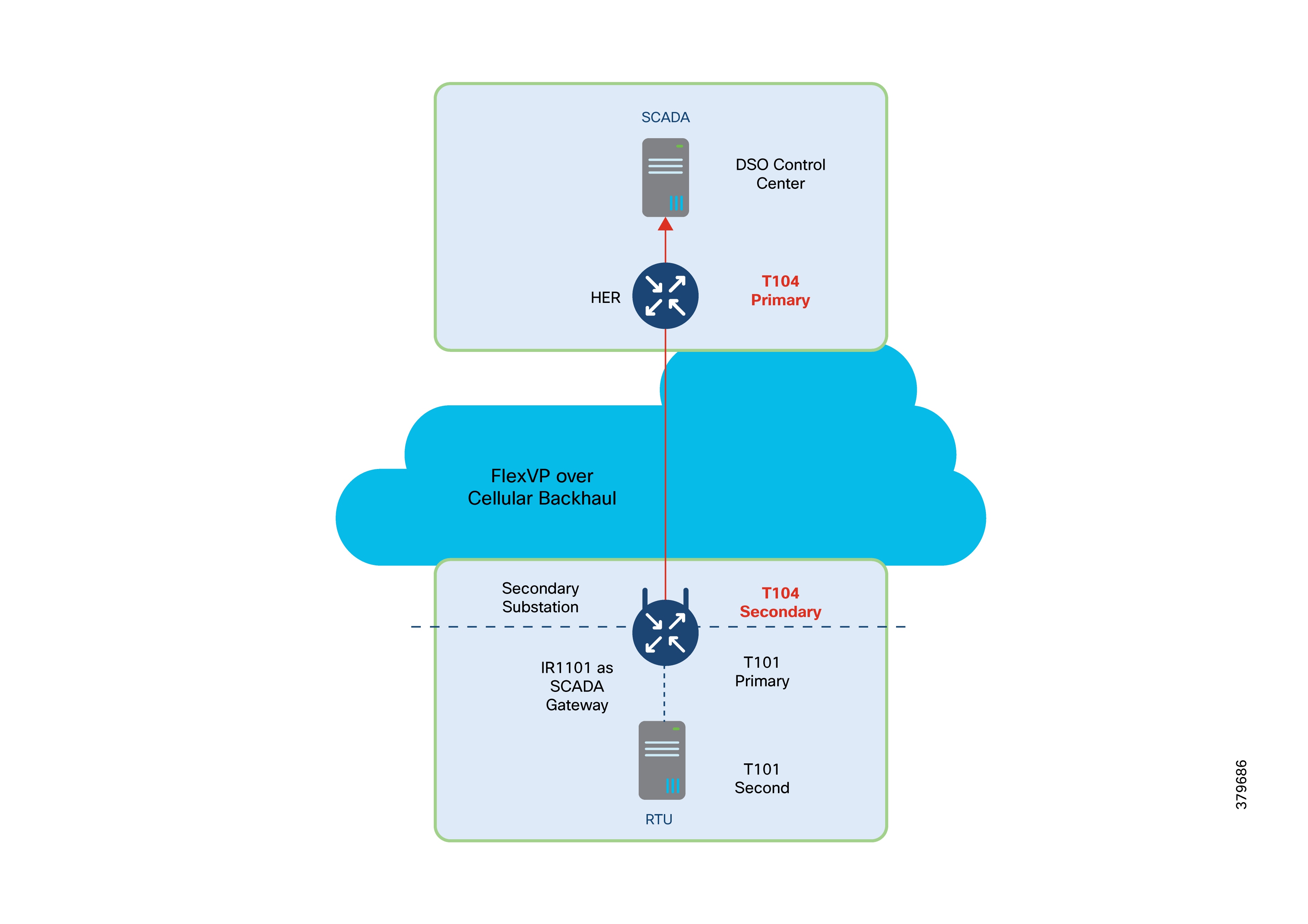
T101/T104 Protocol translation features:
● T101/T104 refers to the IEC 60870-5-101 and IEC 60870-5-104 standard, respectively.
● T101 supports point-to-point and multi-drop links over serial communications.
● T104 uses Transmission Control Protocol (TCP)/IP transport and network protocols to carry the application data (Application Service Data Unit (ASDU)), which was specified in T101.
● Allows balanced and unbalanced communication types:
◦ Balanced mode is limited to point-to-point links where either station can initiate a transaction (similar to Distributed Network Protocol 3 (DNP3) unsolicited response).
◦ Unbalanced mode is suitable for multi-drop links where only the primary station can send primary frames. (Similar to DNP3/ DNP3 IP.)
Protocol translations features:
● Serial Stack:
◦ Poll all data from RTU every 90 seconds.
◦ Provide local time to RTU every 90 seconds.
◦ Support file transfer to and from RTU.
◦ Enable/disable of unsolicited response on RTU.
● IP Stack:
◦ Respond to control center request with local data.
◦ Trigger counter interrogation to RTU when receiving such a request from the control center.
◦ Trigger control transaction to RTU when receiving such a request from the control center.
◦ Support file transfer to and from the control center.
◦ Enable or disable sending unsolicited response to the control center.
The following figure depicts a multi-primary scenario protocol translation scenario where the SCADA Gateway router establishes two different TCP connections with the SCADA primary in the primary and secondary control centers.
Both SCADA primaries will be able to poll and control the RTU.
If the RTU needs to send an unsolicited report, the SCADA Gateway will replicate the report to both SCADA primaries.
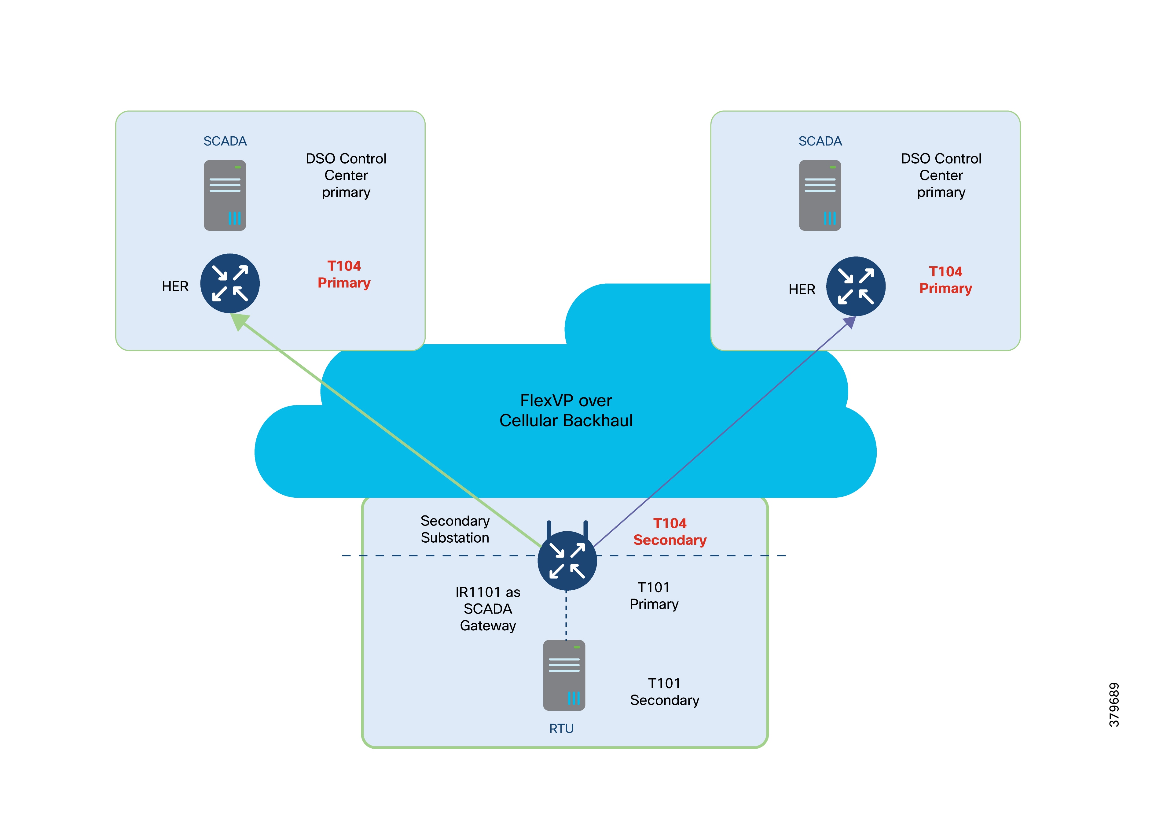
The IoT Gateway has the capability to support NAT as well as Port Address Translation (PAT). This figure captures a couple of deployment scenarios, one involving NAT-PAT and the second scenario without any NAT-PAT.
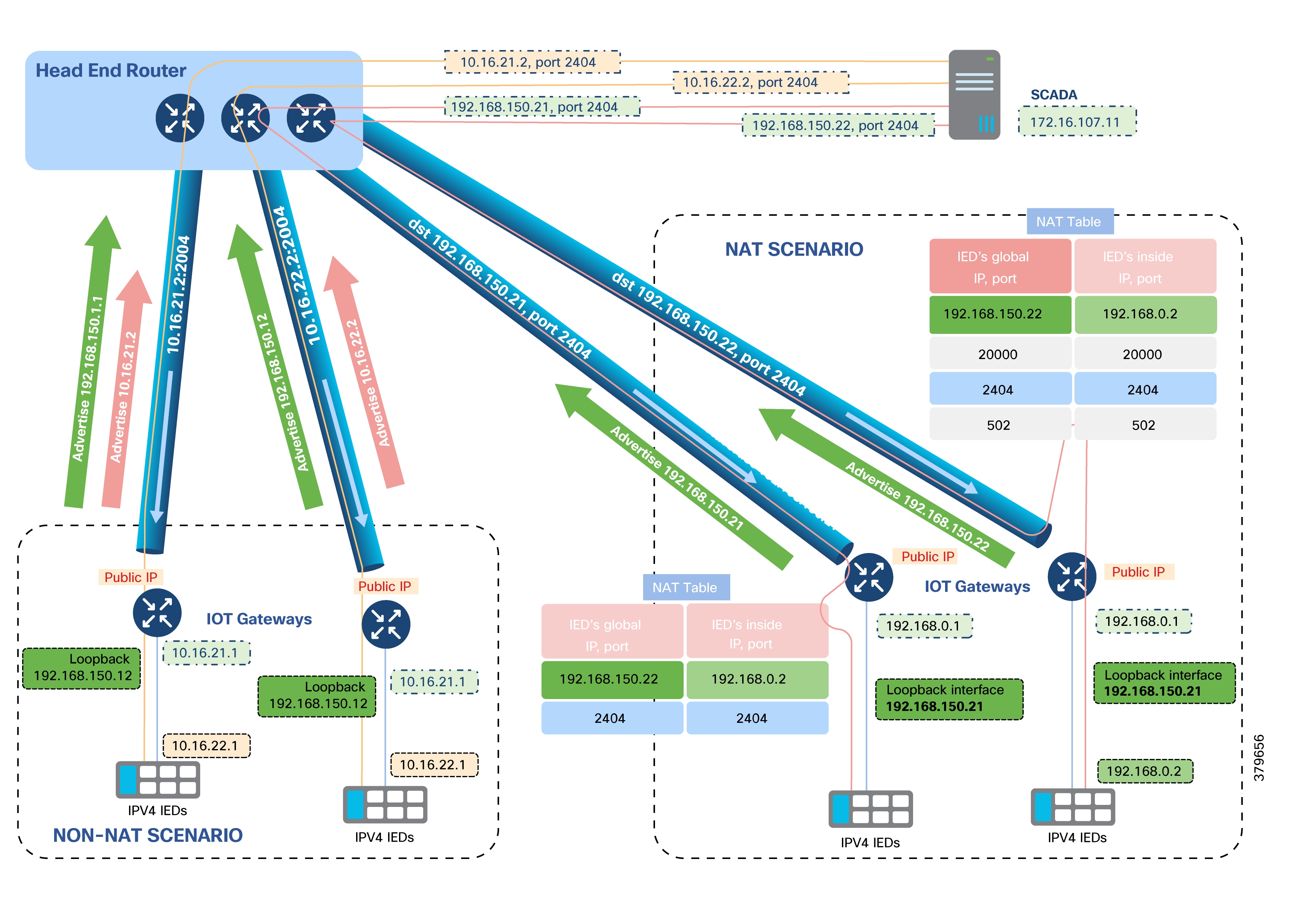
Table 16. Comparison of NAT and non-NAT scenarios
| Non-NAT Scenario |
NAT Scenario |
| SCADA communicates with the IED IP on the application port number. In Figure 41, the SCADA communication is sent to 10.16.21.2 port 2404 directly. |
SCADA communicates with IoT Gateway's loopback IP address, on application or custom port number. IoT Gateway translates the communication and sends it to the IED on Application/Custom port number. In Figure 41, the SCADA communication is sent to Loopback IP of Gateway (192.168.150.21) on port 2404. Then, based on the NAT Table, the address is translated to 192.168.0.2 port 2404, and the communication is sent to the IED. |
| All ports of that IED's IP address are open for communication. This may be a potential security risk. |
Only desired application ports are open at the IoT Gateway for IED communications, enhancing IED security. For example, when the IED is supposed to receive T104 traffic, the IoT Gateway could be remotely provisioned (from Cisco IoT FND) to open the default port 2404 of T104 (or) any custom port. |
| Each IED must be configured with utility scope routable IP address, along with IoT Gateway's interface configurations. This method could consume twice the utility scope routable IP address for each IED. Configuring hundreds of thousands IEDs with unique Ips could result in a huge overhead. |
All IEDs can be configured with the same IP address (for example, 192.168.0.2). The overhead in configuring hundreds of thousands of IEDs with unique and correct utility scope routable IP address is minimized. To make the IED deployment easier, the IP address of 192.168.0.2 could be allocated to the IED, if the IED is capable of sending the DHCP request. Cisco IoT FND helps provisioning IoT Gateway remotely and easily:
● Provision the IoT
Gateway
port
serving
the
IED
with
192.168.0.1.
● Provision DHCP
server
functionality
on
the
IoT
Gateway
to
serve IEDs with IP address
dynamically.
|
| Every IoT Gateway must advertise the IP address of the IED, as well as its loopback address. |
The IoT Gateway only advertises its loopback address, which uniquely represents the IoT Gateway. |
| IEDs to be allocated with routable addresses within the utility network scope, which could be an overhead for scaled number of deployments. |
No overhead associated, as IED IP is not advertised. This method is scalable as it is similar to PNP for IED, if IED is configured for DHCP. |
| Network reachability information of each IED connected to their respective IoT Gateways must be available in the HER's routing table, thus consuming more memory space and impacting scalability. |
IED can be reached over IoT Gateway's loopback address itself. IED reachability is masked by the IoT Gateway. This approach requires lesser memory resource on the HER, making it scalable. |
| Migration from one subnet to another subnet requires IED reconfiguration. |
No IED reconfigurations are required. Any configuration changes could be handled at the IoT Gateway layer itself, using Cisco IoT FND. |
| Since the IP address of the IED itself is advertised, all the port numbers on the IED are exposed to communication requests and denial of service attacks. |
Only the application ports that the IED serves (for example, port 2404 while serving IEC 60870-5-104) are opened up at the IoT Gateway, enhancing security. Any communication attempt on another port number is cut off at the IoT Gateway, freeing up CPU cycles and allowing IED to process only Interesting traffic. |
| Once the IED is configured to listen on certain port number (for example, 2404) and deployed on the field, if the SCADA server wants to establish communication on a different port number, IED reconfiguration is needed. |
Since the IED is network and port translated at the IoT Gateway, the SCADA could communicate with the IoT Gateway on any custom port number, and the IoT Gateway could translate the communication to 192.168.0.2 on port 2404 (which the IED is configured to receive). |
| IED is at risk of attacks since its IP address is exposed. The risk can be mitigated with ACLs on the cellular interface, permitting communication only from the DSO headend through the FlexVPN tunnel. |
Only the FlexVPN tunnel interface configured to receive NAT inbound traffic from the DSO headend (ip nat outside enabled on Tunnel interface). The only way to reach the IED is through the secure tunnel from the DSO Control Center. Incoming traffic on any interface other than secure tunnel interface is dropped, as the translation works only for NAT-enabled ports. As ip nat outside is not enabled on the cellular interface, even if there is an attack on cellular interface on port 2404, the attack is dropped at the IoT Gateway and never reaches the IED. The IED continues to communicate with the SCADA headend on port 2404. No one on the Internet would be able to connect to IED (NAT or PAT) unless they come through the secure tunnel from the DSO headend. |
| IP address of the IED is reachable to DSO headend only after a secure FlexVPN tunnel is established. |
IP address of the IED is not exposed. Only the IP address of the loopback interface is exposed, which is reachable to DSO headend after a secure FlexVPN tunnel is established. SCADA reaches the IED using the IoT Gateway's loopback address, on application port numbers (port number 20000 for DNP3, 2404 for IEC 60870-5-104, or any custom port), as per the configuration provisioned remotely from Cisco IoT FND. Additional ports can be opened on IoT Gateway for an IED at any time, through remote reprovisioning using Cisco IoT FND. |
| Relatively faster. |
Relatively slower as NAT consumes extra CPU cycles on the IoT Gateway. Typically, the IoT Gateway is powerful enough to handle this with ease. |
| End-to-end IP reachability exists. |
End-to-end communication is not permitted by design. Only specific application ports are open. |
| Ping test from SCADA is responded to by the IED. |
Ping test from SCADA is responded by the IoT Gateway as the communication point is the loopback IP of the IoT Gateway, and not the IED. |
A non-NAT scenario can be secured using ACLs on the cellular port to denying access to the IED IP. At the same time, the SCADA communications from the DSO headend to IED could be honored, as it arrives over the encrypted tunnel, and therefore should be able to reach the IED.
Note: NAT usage is recommended as it can ease deployment and scalability, if end-to-end traceability is not mandatory.
Quality of Service (QoS) and Class of Service (CoS) enable the network to prioritize critical traffic, resulting in improved and more predictable service. Key mechanisms include:
● Dedicated Bandwidth: Ensuring different upload/download throughput for cellular links.
● Reduced Loss: Prioritizing DA real-time traffic.
● Congestion Management: Supporting multiple service types.
● Traffic Prioritization: Assigning priorities to different service capabilities.
QoS is essential in multi-service DA solutions to differentiate and prioritize traffic, such as AMI, distribution automation, remote workforce, and network management. It is important to account for transport losses, delay, and jitter, especially when limited bandwidth is available on WAN backhaul links.
For dual-WAN interfaces with differing bandwidth (such as cellular), QoS policies must prioritize which traffic is allowed or dropped.
DA solutions can apply QoS DiffServ and IEEE 802.1p CoS to:
● IPv4 Traffic: FLISR, protocol translation, network management
● IPv6 Traffic: IPv6 IED AMI, network management
● Layer 2 Traffic: IEC 61850 GOOSE/SV and traffic bridged between substations
The following figure shows traffic priorities. IP protocols are classified using DSCP, while Ethernet Layer 2 protocols like GOOSE) use CoS.
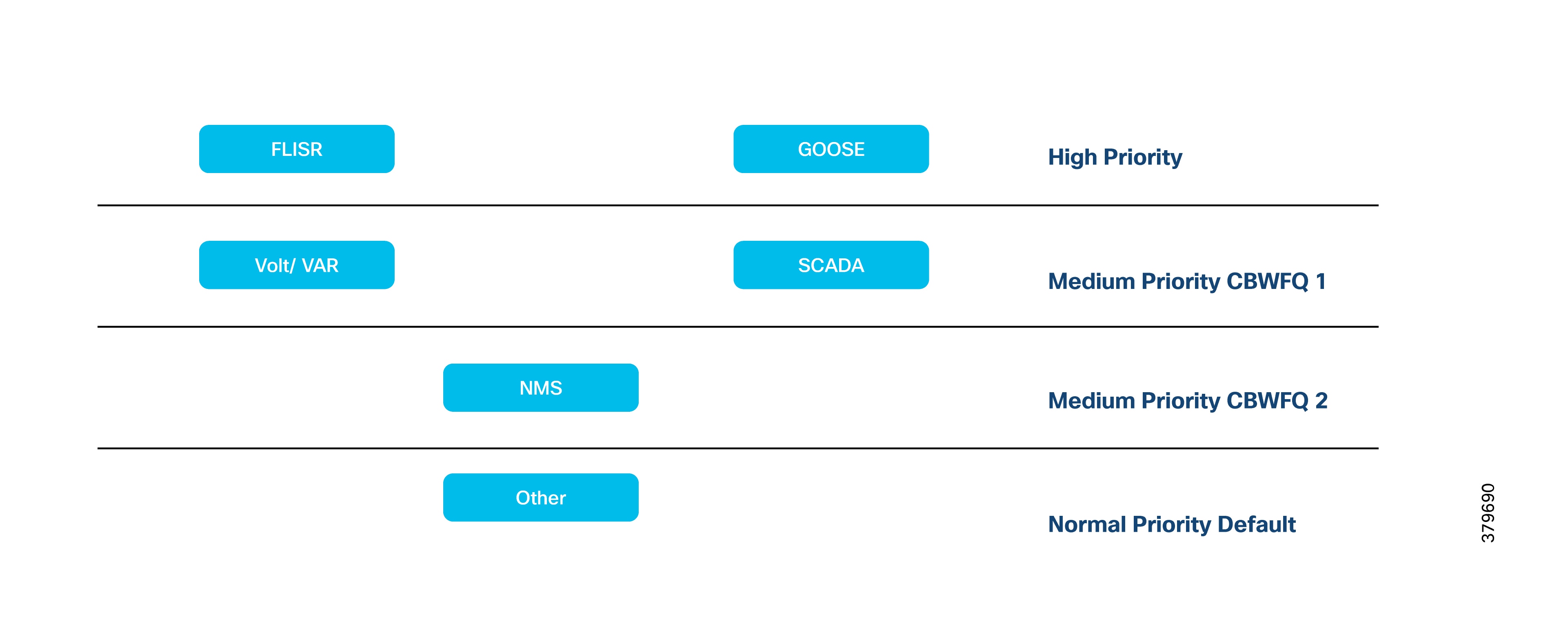
QoS follows the IETF DiffServ model. QoS may be specified using IP Precedence bits or source/destination addresses, supporting classification, marking, shaping, policing, and intelligent queuing.
SSR or DA Gateways perform QoS actions onLayer 3 interfaces. The QoS action sequence on egress traffic is:
1. Classification
2. Marking
3. Queuing
Upstream QoS: from IED to SCADA
DA IEDs perform marking. Alternatively, the DA Gateway or SSR can mark packets if the IED does not support it.
Queuing is performed on the egress WAN interface, based on DSCP values.
Table 17. Upstream QoS
| Traffic |
Queue |
| High-priority FLISR and GOOSE traffic |
Low Latency Queue |
| Medium-priority (Volt/VAR, MMS) |
Class-Based Weighted Fair Queue 1 |
| Cisco IoT FND Network Management |
Class-Based Weighted Fair Queue 2 |
| Remaining traffic |
Default queue |
Note: Use percentage-based queue bandwidth rather than fixed values for portability across different interfaces.
If RTUs connect via RS232 asynchronous serial and raw sockets are enabled, marking can be applied on the serial line.
HER (Cisco Catalyst 8500) supports advanced QoS, including DoS protection for Cisco IoT FND and SCADA applications.
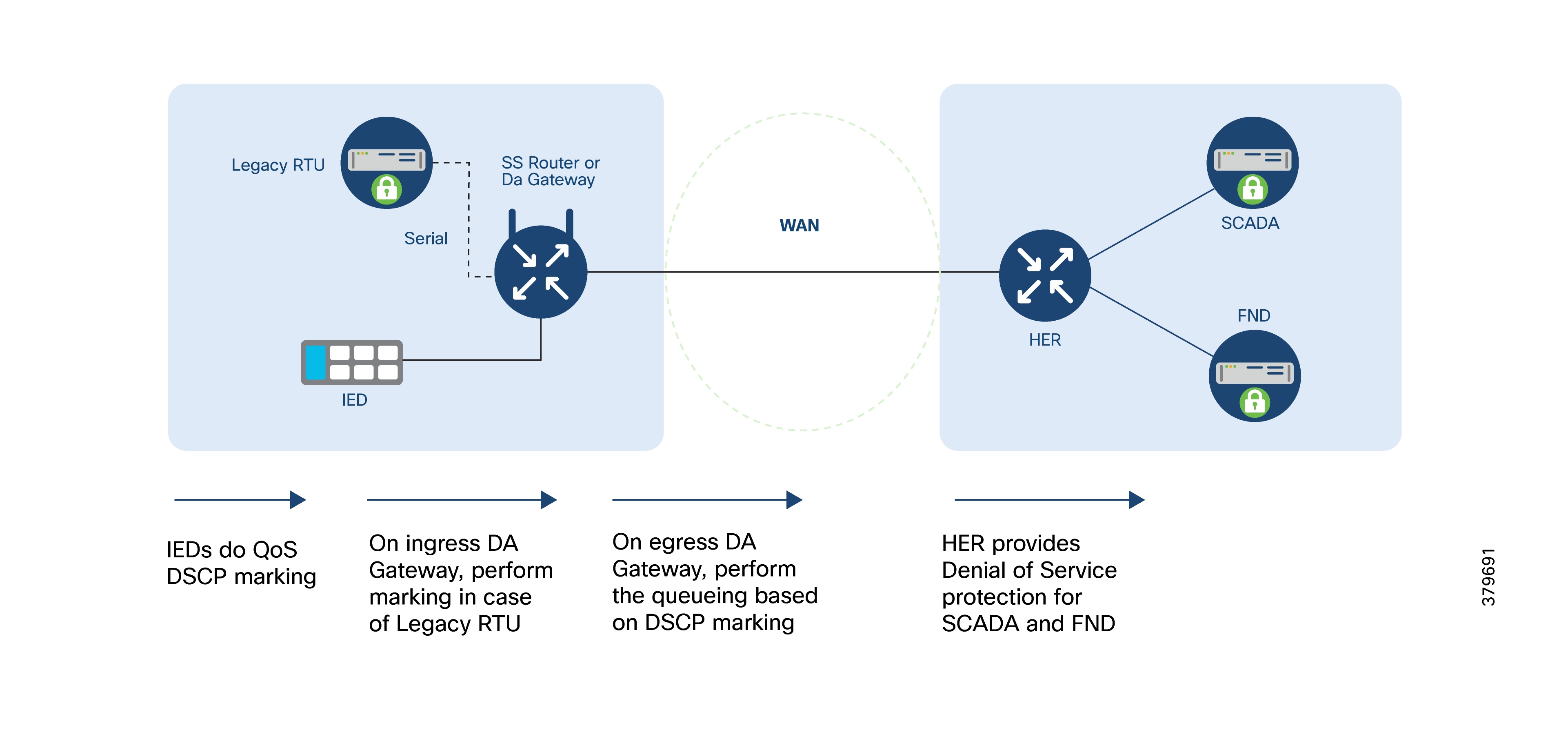
Downstream QoS (from SCADA to IED):
● SCADA and Cisco IoT FND applications generate DSCP markings based on message priority.
● HER (Catalyst 8500) shapes and applies policies on egress traffic based on DSCP, providing DoS protection and prioritization.
● DA Gateway queues packets per DSCP.
Note: QoS is always per-hop.
Traffic prioritization at the gateway may be overridden by the service provider’s prioritization rules. Ensure an SLA is in place if the gateway’s QoS must be honored by the service provider.
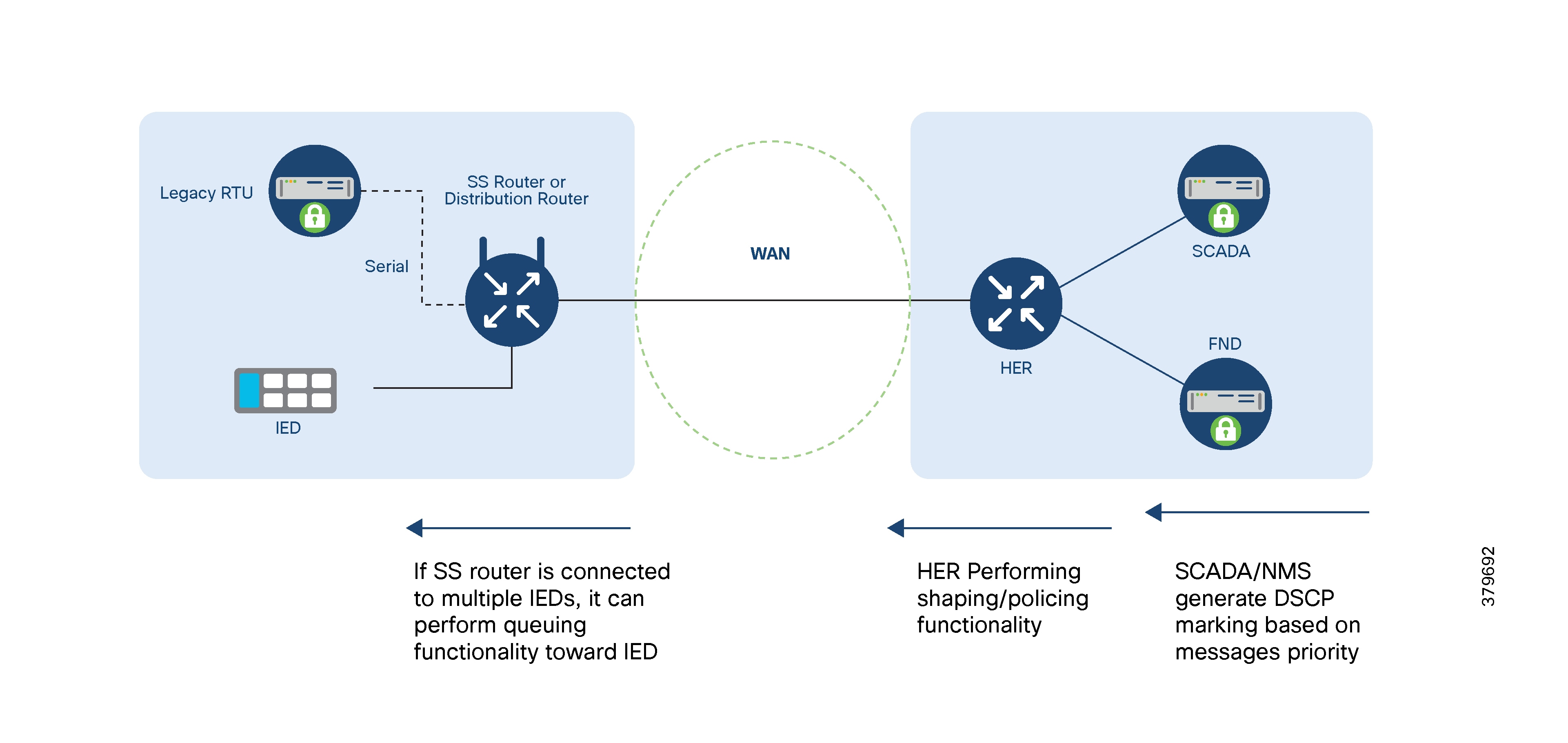
Many DA Secondary Substation applications require precise event time-stamping for correct sequencing and ordering. Timing synchronization can be achieved using protocols with varying accuracy requirements.
Table 18. Timing synchronization
| Description |
Required Synchronization Accuracy |
Details |
| DA FLISR |
10 to 100 ms |
Real-time fault location and isolation |
| DA FLISR |
1000 ms |
Isolation and restoration (protection is assumed to occur locally) |
| DA Volt/VAR |
10 ms |
Integrated Volt/VAR |
| DA Volt/VAR |
1000 ms |
SCADA-based Volt/VAR |
NTP provides 10–100 ms accuracy depending on network characteristics. NTP version 4 is deployed, with the NTP server in the control center and DA Gateways and SSR acting as clients.
Two DHCP services are used:
1. Staging Phase of ZTD
During staging, DHCP server-assisted PnP provisioning advertises the PnP server details to the IoT Gateway along with its IP address using Vendor Specific Options. For more information, refer to Cisco Network Plug and Play Agent configuration.
2. Tunnel Provisioning Phase of ZTD
Cisco IoT FND requests IPv4 and IPv6 addresses from the DHCP server on behalf of the IoT Gateway. Once received, FND assembles the tunnel provisioning configuration and pushes it to the IoT Gateway via the TPS. These addresses uniquely identify the IoT Gateway to FND and SCADA.
Zero Touch Onboarding of Cisco IOS-XE Routers
This document considers Cisco IoT FND as the Network Management platform as well as the PnP server in the zero touch onboarding process.
Zero Touch Deployment (ZTD) is used to onboard large numbers of SSRs and DA Gateways efficiently, requiring minimal manual intervention. The Field Network Director (FND) serves as the network management platform and PnP server for bootstrapping using the PnP protocol.
Field technicians only need to mount and power up devices; ZTD handles the rest.
ZTD reduces total cost of ownership, especially for large-scale deployments.
ZTD occurs in two stages:
1. Staging of Cisco IoT Gateway:
The Gateway is given minimal (express or day 0) configuration, either manually or automatically via Plug and Play (PnP). PnP bootstrapping is a dynamic procedure that can be used for express configuration of IoT Gateway.
2. Deployment of Cisco IoT Gateway:
After bootstrapping, the device:
● Receives a dynamic WAN IP (Ethernet or cellular)
● Obtains a Utility PKI-signed certificate via SCEP
● Establishes a secure tunnel to the DSO headend via TPS
● Receives application and operational configurations
● Sends periodic status updates to Cisco IoT FND
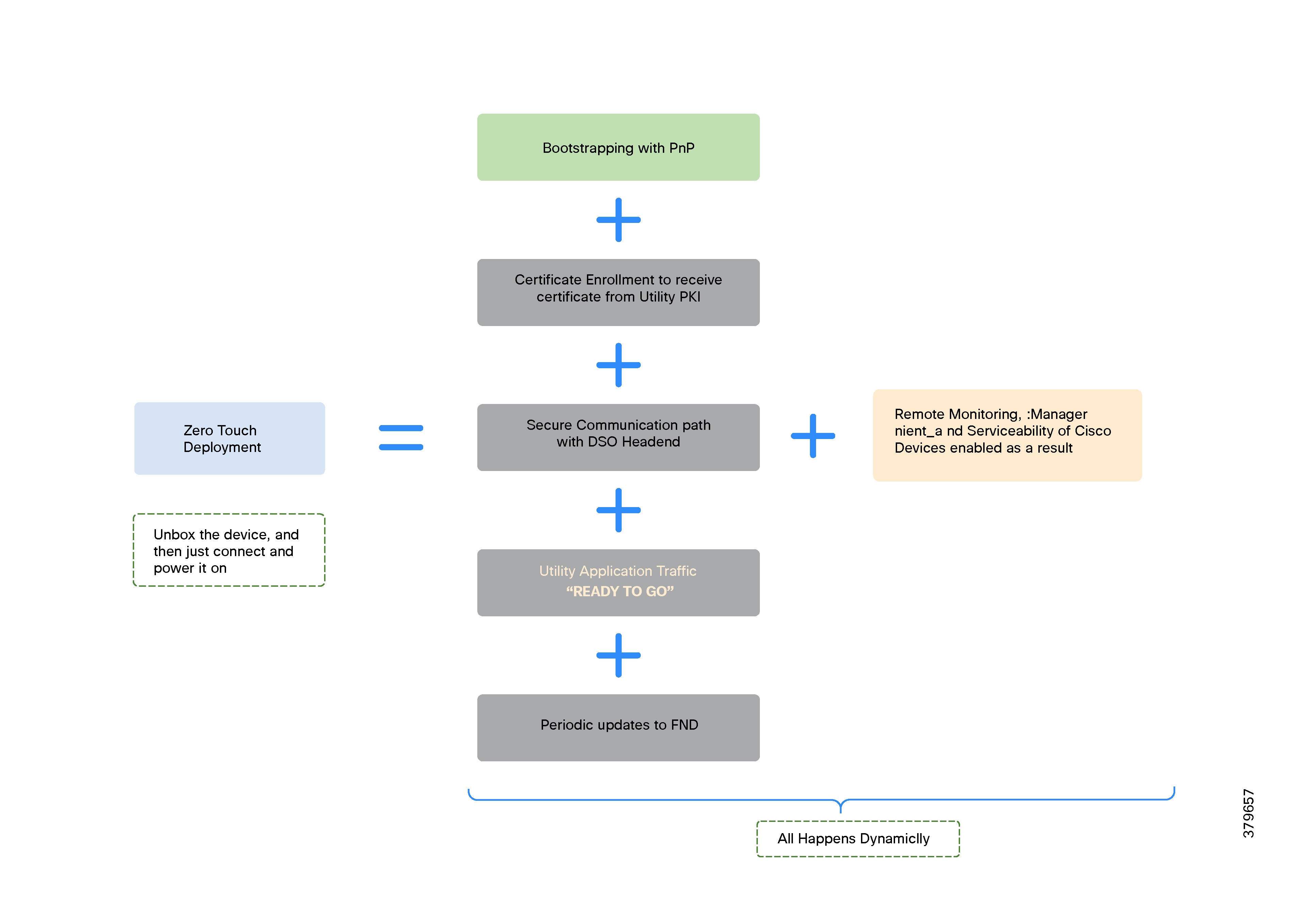
References:
● Cisco FAN Headend Deep Dive Implementation and FAN Use Cases
Cisco Network Plug and Play (PnP)
PnP is a secure, scalable solution for Day-Zero provisioning of Cisco IoT gateways (such as IR1101), running as an add-on to IoT FND.
PnP automates bootstrapping by loading express configuration onto routers, complementing the ZTD process.
● Eliminates manual staging steps, reducing human error.
● Ensures consistency through template-based configuration.
● PnP agent
● PnP server
● PnP proxy
If the Cisco IoT Gateway starts without a configuration, the PnP server discovery process is triggered automatically by the integrated PnP agent in Cisco IOS.
When PnP server discovery is in progress, any key press on the Cisco IoT Gateway console could terminate the PnP server discovery procedure since it's a manual intervention on the router.
Both cost saving and time saving are achieved, since staging is dynamically addressed.
● DHCP server
● DNS server
● Cisco PnP Connect (Cloud Redirection Service)
● Manual PnP profile
The chosen bootstrapping location and network type (LTE or Ethernet) determine the discovery method.
Note: If TPS is used as a PnP Proxy, advertise the proxy’s IP/FQDN instead of the PnP server’s address.
Note: After server discovery using DHCP, DNS, or PnP Connect, a PnP profile is dynamically created on the IoT Gateway.

PnP Server Discovery Through DHCP Server
PnP server discovery through DHCP is a dynamic method for identifying the PnP server address. When a Cisco router boots, the PnP agent first attempts DHCP server-assisted provisioning. If successful, the router receives the PnP server's details and initiates bootstrapping.
The PnP server’s IP address or FQDN is delivered using vendor-specific DHCP options:
● Option 43 is used for IPv4 networks.
● Option 9 is used for IPv6 networks.
Notes:
● The PnP agent sends a case-sensitive “ciscopnp” string in DHCP option 60 during discovery.
● DHCP-based discovery occurs over the Layer 3 WAN port. If the WAN port is configured as Layer 2, the corresponding Layer 3 SVI interface can be used for DHCP.
The DHCP server can be configured with multiple classes to match different option 60 strings from various devices. Upon a match, the server returns the appropriate vendor-specific option with the PnP server detail.
Utilities must either control the DHCP server or have an agreement with the service provider to handle the ciscopnp option 60 string and provide the required vendor-specific option for Cisco IoT gateways.
In the following figure,
1. The PnP-capable Cisco IoT gateway sends out a DHCP request
2. The DHCP server advertises PnP server details using DHCP option 43 for IPv4, resulting in the dynamic creation of the PnP bootstrapping profile on the Cisco IoT gateway.
3. As the server detail includes an FQDN, the gateway performs a name resolution and sends out the bootstrapping request to the PnP proxy.
4. The express configuration is pushed onto the Cisco IoT gateway.
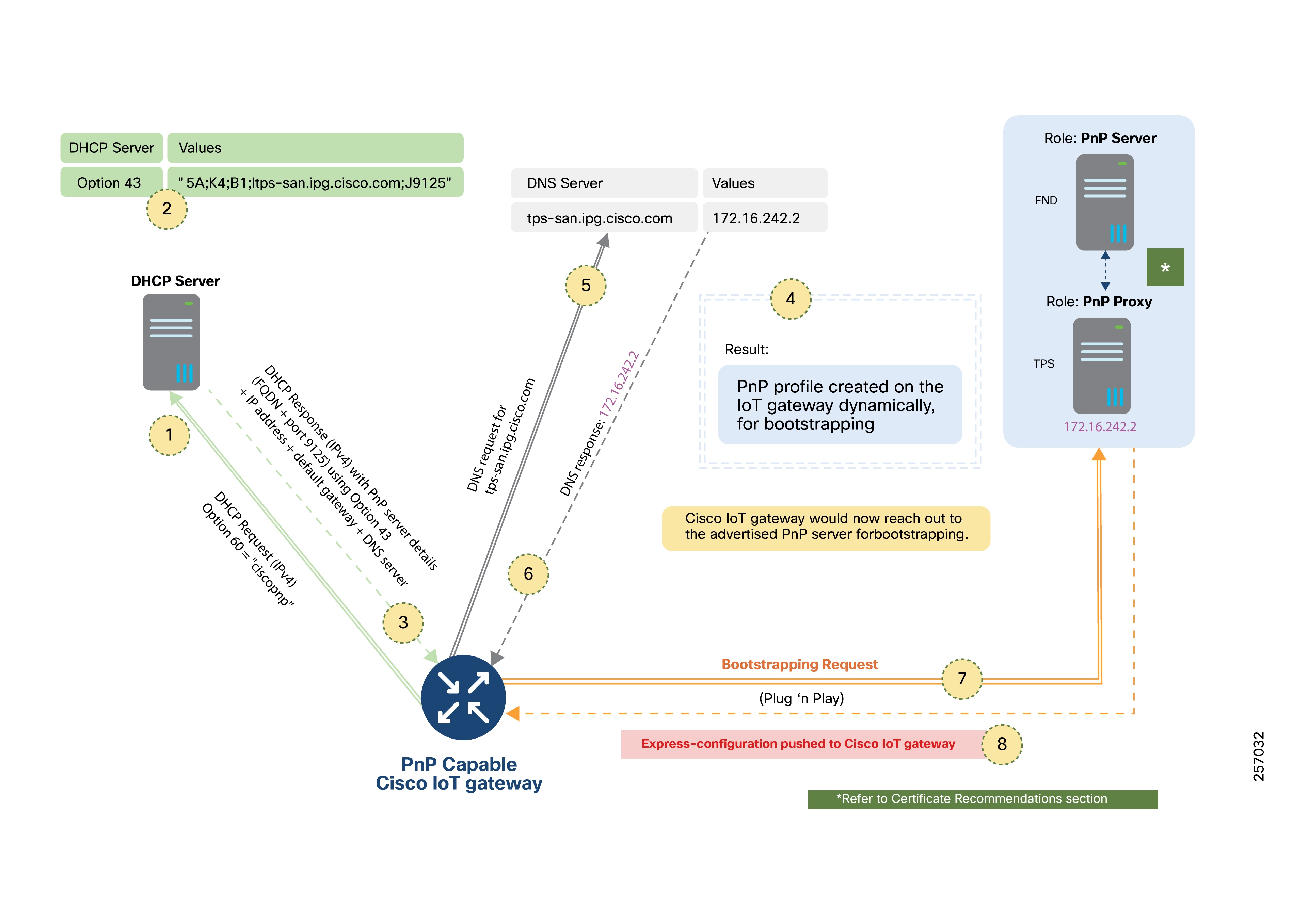
In the following figure:
1. The PnP-capable Cisco IoT gateway sends out a DHCP request
2. The DHCP server advertises PnP server details using DHCP option 9 for IPv6, resulting in the dynamic creation of the PnP bootstrapping profile on the Cisco IoT gateway.
3. As the server detail includes an FQDN, the gateway performs a name resolution and sends out the bootstrapping request to the PnP proxy.
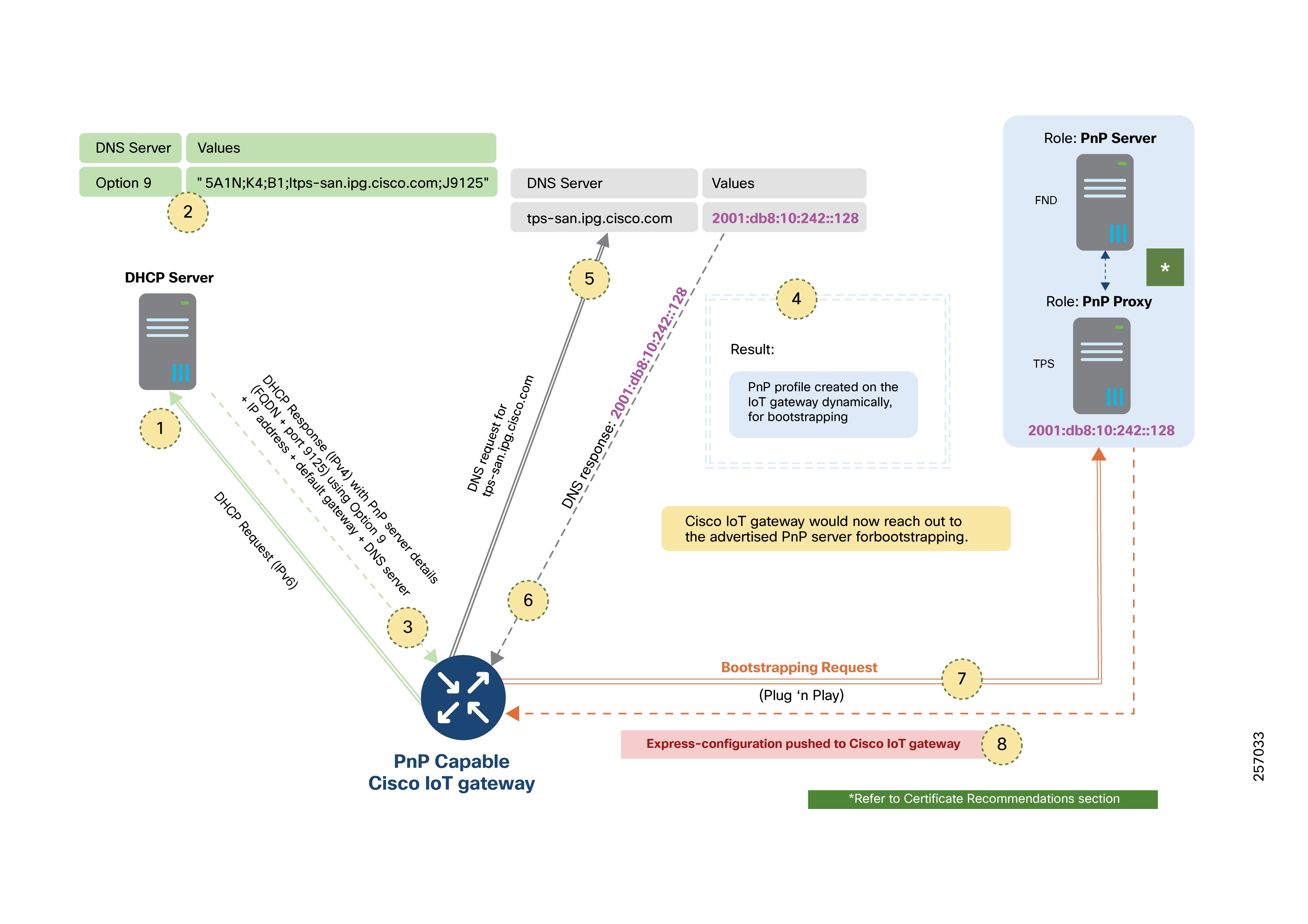
In the following figure:
1. The DHCP server advertises the IPv4/IPv6 address (instead of FQDN) under vendor-specific option 43 or option 9.
2. The DHCP response, once received by the Cisco IoT gateway, results in dynamic creation of the PnP bootstrapping profile.
3. The bootstrapping request is then sent to the advertised PnP proxy IP address on port 9125.
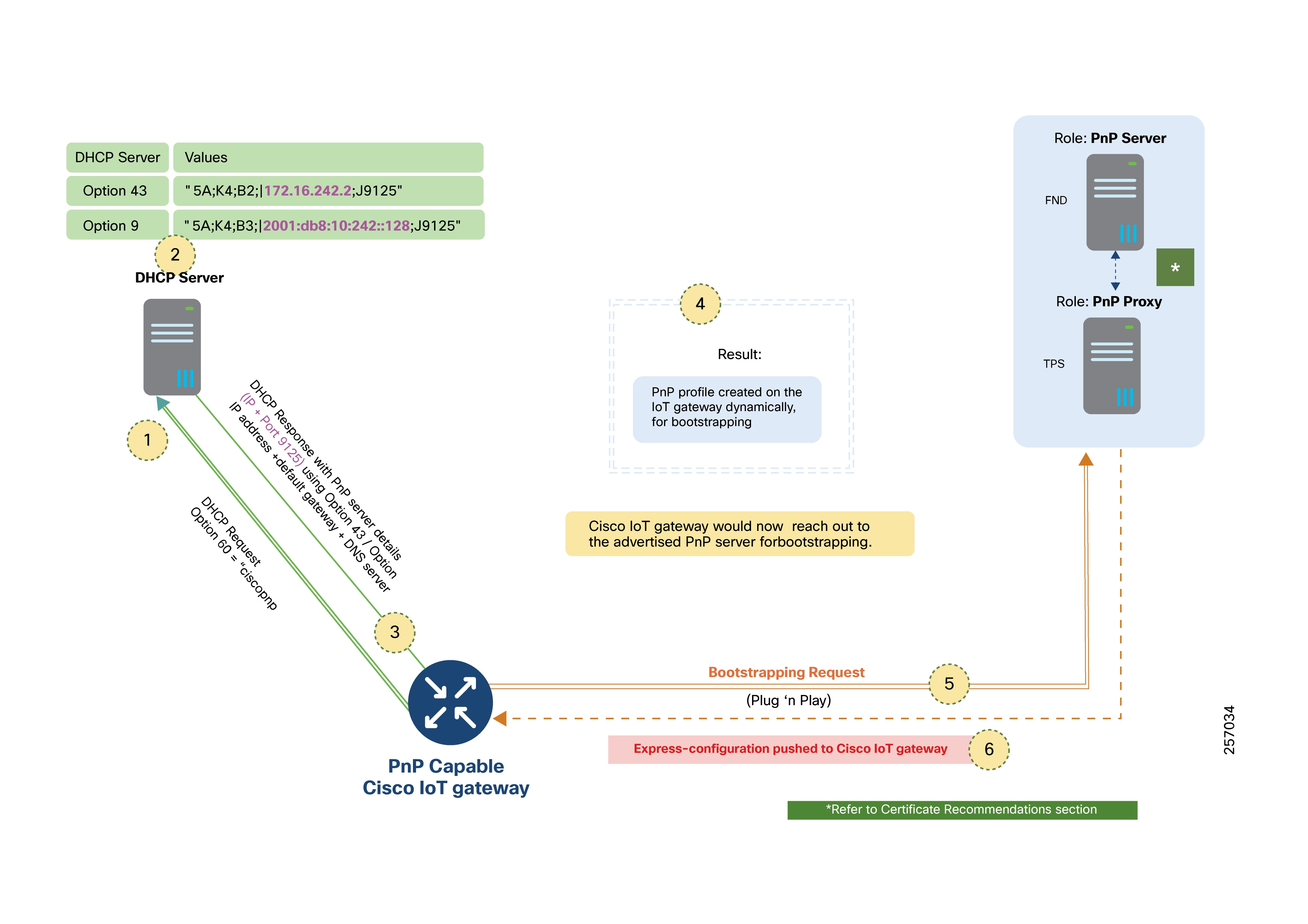
PNP Server Discovery Through DNS Server
If DHCP does not return PnP server details, the gateway attempts DNS server-assisted discovery. The domain name advertised in the DHCP response (for example, domain.com) is used to resolve the PnP server’s address at pnpserver.domain.com.
The DNS server must be configured with:
● An “A record” for the IPv4 address of the PnP server, or proxy, or both.
● An “AAAA record” for the IPv6 address of the PnP server, or proxy, or both.
Note: Utilities must control the DNS server or have an agreement with the IP provider to add necessary records.
In the following figure:
1. The gateway queries the DNS server for pnpserver.domain.com.
2. Upon successful resolution, a PnP profile is created and bootstrapping proceeds.
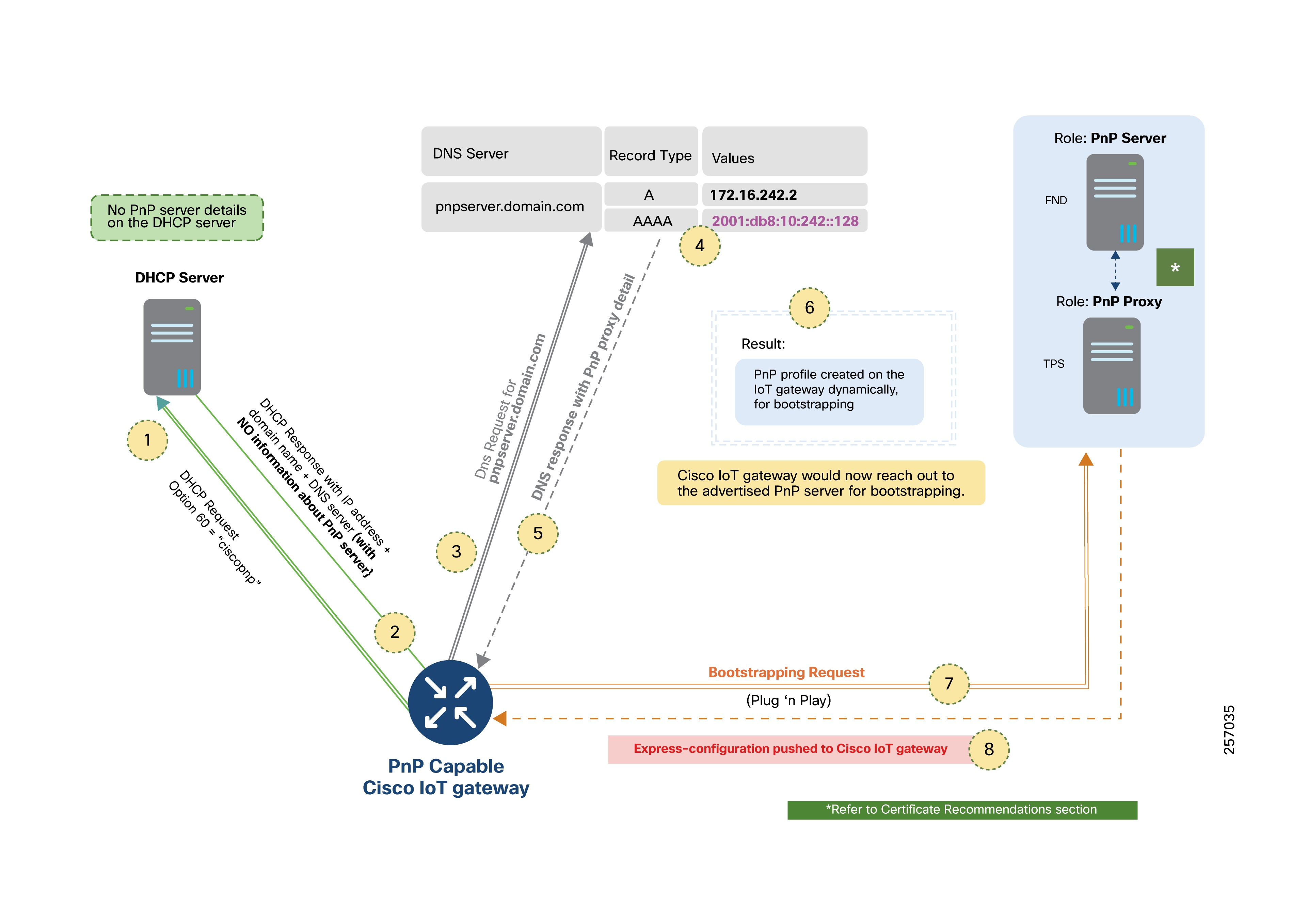
PnP Server Discovery Through Cisco PnP Connect
If neither DHCP nor DNS provide PnP server details, Cisco PnP Connect is used.
This method requires a Cisco Smart Account on the software.cisco.com portal, where IoT gateways are registered either during ordering or manually added to the Smart Account later.
The controller profile on PnP Connect specifies the PnP proxy/server details, and the registered Gateway must be mapped to the correct profile.
Operational Flow:
1. The gateway contacts devicehelper.cisco.com.
2. The cloud service returns the IP or FQDN of the PnP server.
3. The gateway creates a dynamic PnP server profile and initiates bootstrapping.
Note: This method is ideal when DHCP/DNS servers are not managed by Utilities providers, such as when using public Ethernet or LTE networks.
Manual PnP Profile Configuration
Alternatively, the PnP server details can be manually specified on the Cisco IoT gateway.
Reference:
For more details and illustrations, see the Plug-n-Play Agent Discovery Process section in the Cisco Open Plug-n-Play Agent Configuration Guide.
Bootstrapping and Deployment Options
Secure Zero Touch Deployment (ZTD) of Cisco IoT gateways is divided into several phases:
1. Express-configuration provisioning (bootstrapping)
2. Certificate enrollment
3. Tunnel provisioning
4. Device registration
5. Periodic updates to NMS
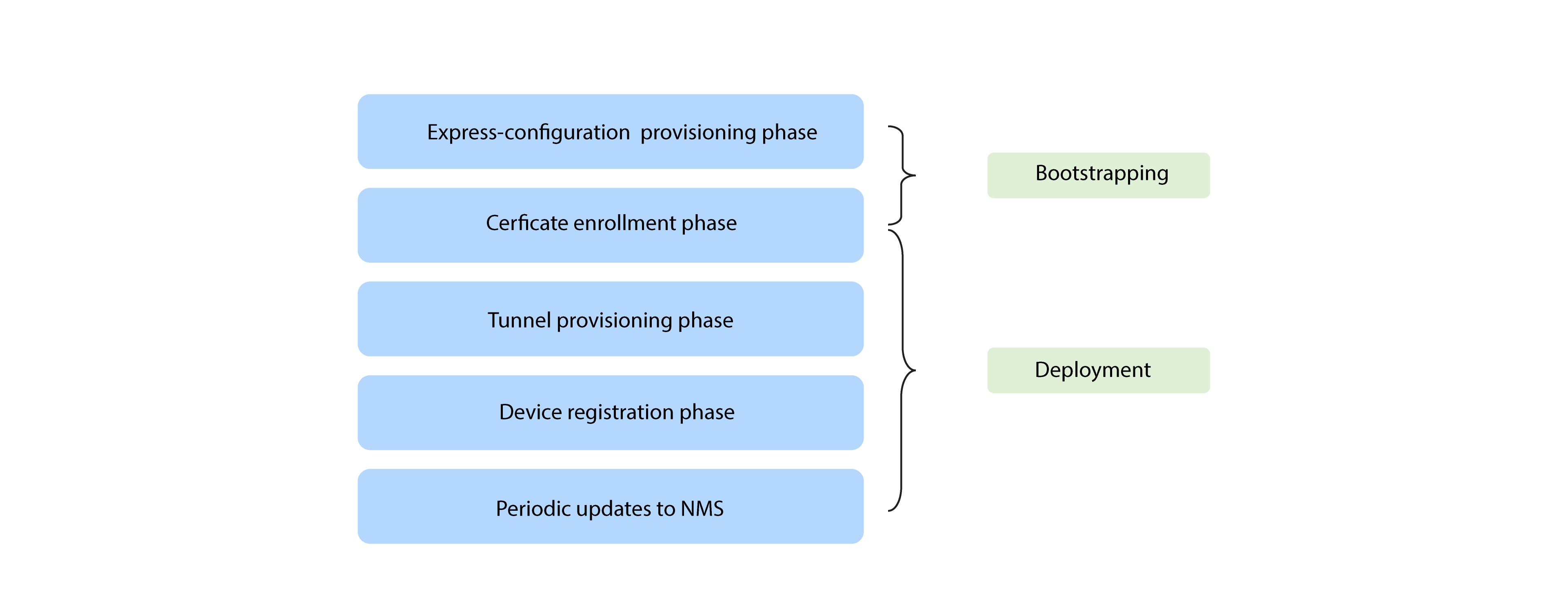
These phases are grouped as:
● Bootstrapping: Express-configuration provisioning
● Deployment: All subsequent phases
The bootstrapping location is the site where PnP is used to initiate Cisco IoT gateways. This can be a dedicated staging area or the actual deployment site.
In the case of dedicated bootstrapping locations, devices are unpacked, PnP bootstrapped, powered off, transported, and then deployed at the final site. Only bootstrapping occurs at the site; deployment is completed elsewhere.
Operational Flow:
1. Device boots with no initial configuration.
2. PnP server discovery is triggered.
3. The gateway connects to the PnP proxy (typically over HTTP port 9125 (or 80), followed by HTTPS port 9120).
4. Express configuration is downloaded. Then, the PnP profile is then removed, concluding bootstrapping.
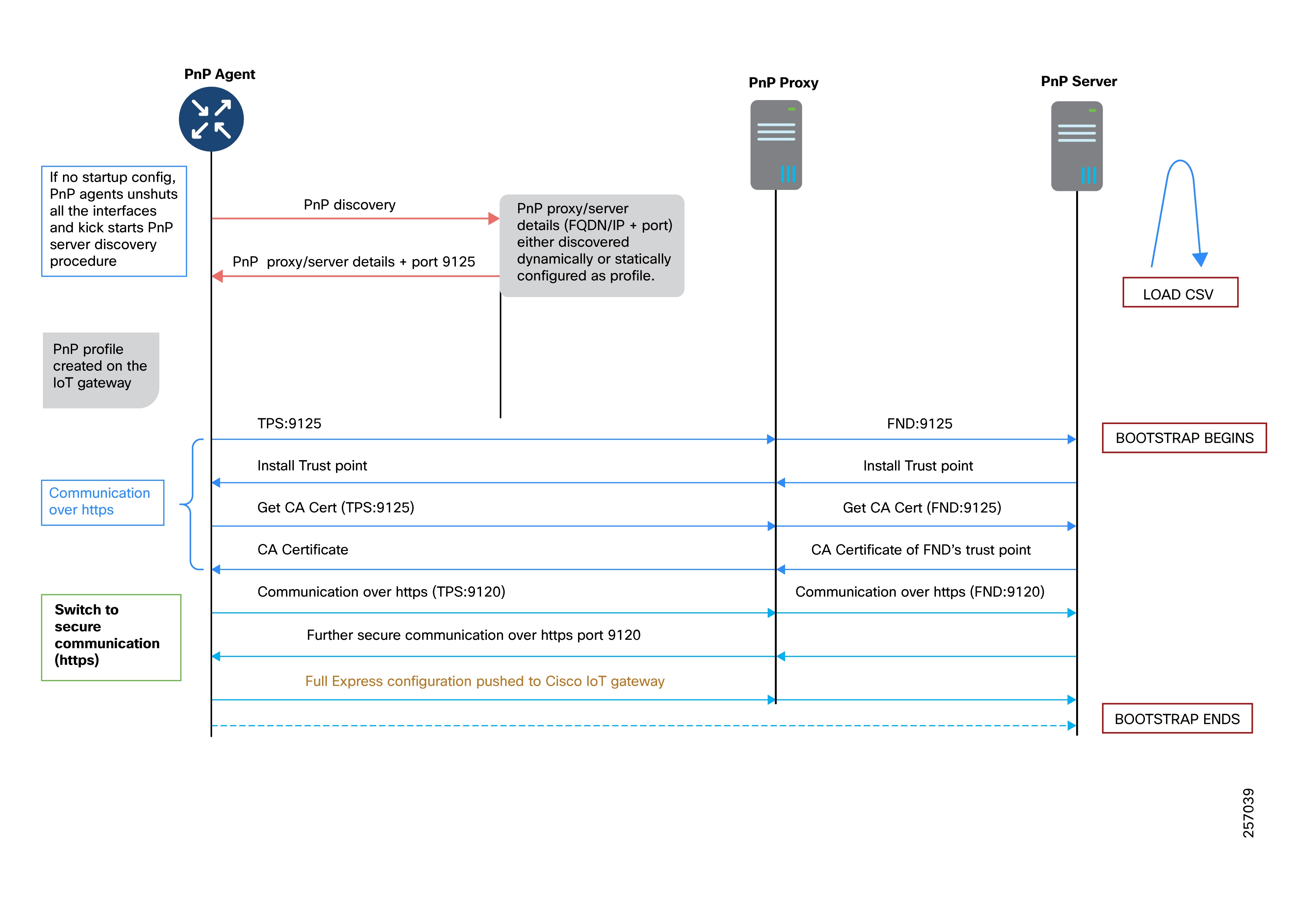
Note: In Cisco FAN solutions, the PnP proxy is usually in the DMZ, and the TPS may also act as the PnP proxy.
The deployment location is where the IoT gateway is finally installed and put into service. Devices may be bootstrapped prior to shipping or directly at the deployment site, depending on operational preferences.
Bootstrapping and Deployment Approaches
Approach 1: Bootstrapping at a Staging Location
Bootstrapping occurs at a dedicated staging premise.
Devices are powered off and transported to deployment sites after bootstrapping.
The PnP proxy/server can be local to the staging site or centrally hosted and accessed over WAN.
Operational Steps:
1. Certificate enrollment via Utility PKI.
2. Secure tunnel provisioning to the DSO Control Center.
3. Enablement of utility application traffic.
4. Periodic status updates to IoT FND.
5. Remote monitoring and management via IoT FND.
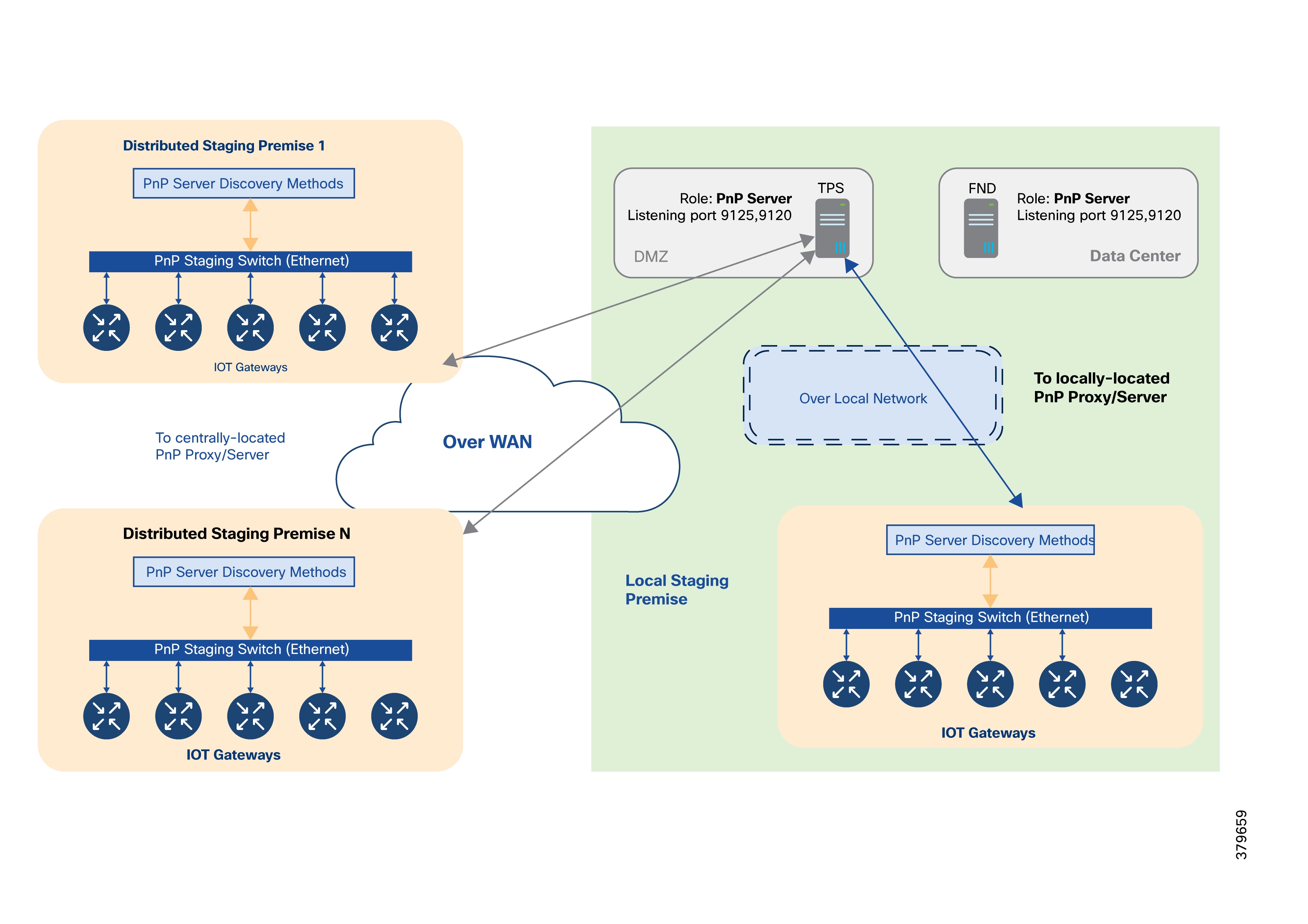
Recommended PnP Discovery Methods:
● DHCP server
● DNS server
● If not possible, Cisco PnP Connect can be used if Internet access is available.
Approach 2: Bootstrapping at the Deployment Location
Devices are unpacked and bootstrapped directly at the deployment site.
A staging premise is not required.
The TPS acts as the PnP proxy and all discovery methods should advertise TPS details.
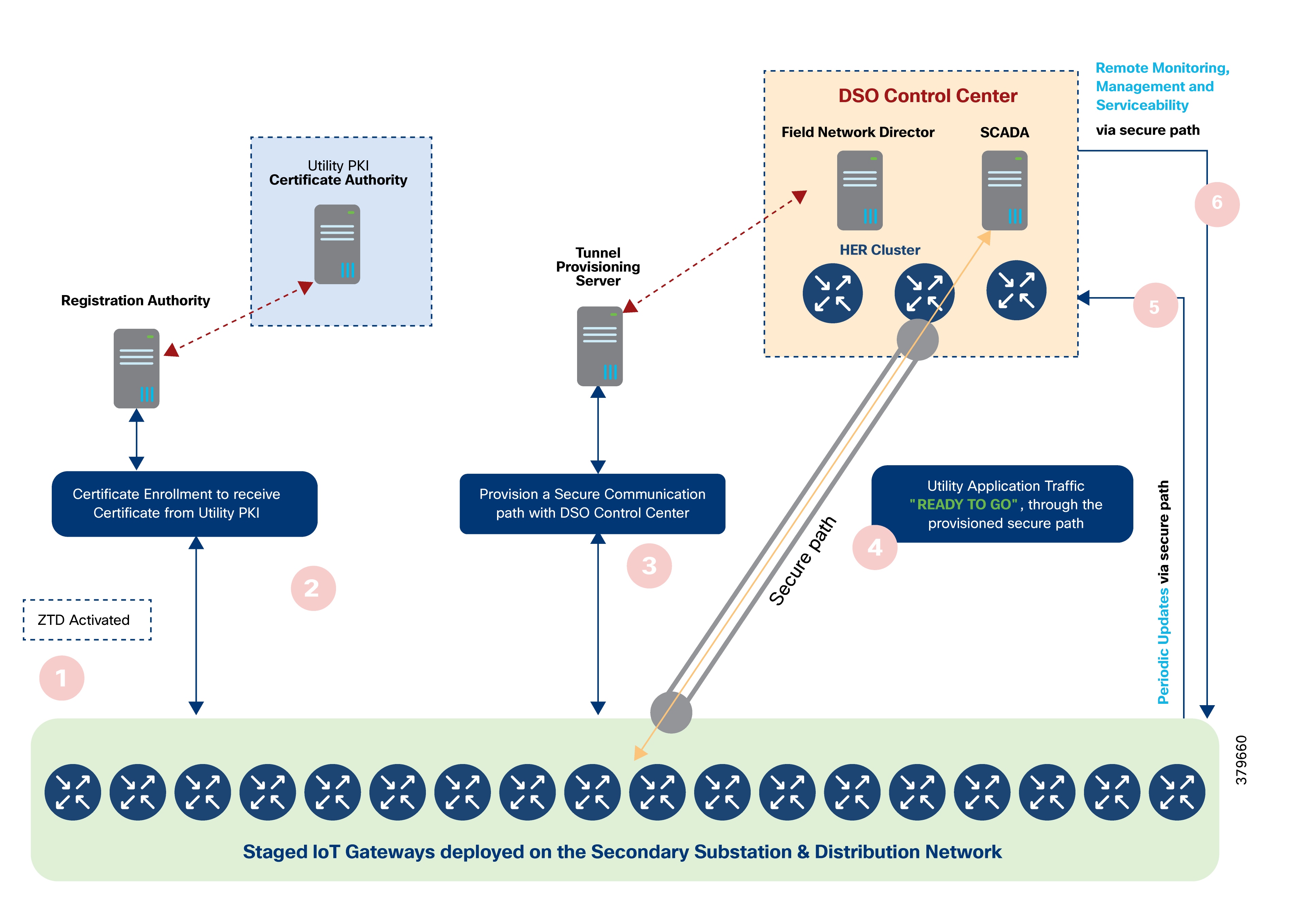
Operational Steps:
1. The gateway discovers the PnP server using any available method.
2. The device contacts the PnP server to initiate bootstrapping.
3. Optionally, the gateway obtains the CA trustpoint certificate from the PnP RA.
4. Upon completion, the express-configuration is applied and ZTD is activated.
5. The gateway continues with certificate enrollment, tunnel provisioning, enabling application traffic, and ongoing monitoring.
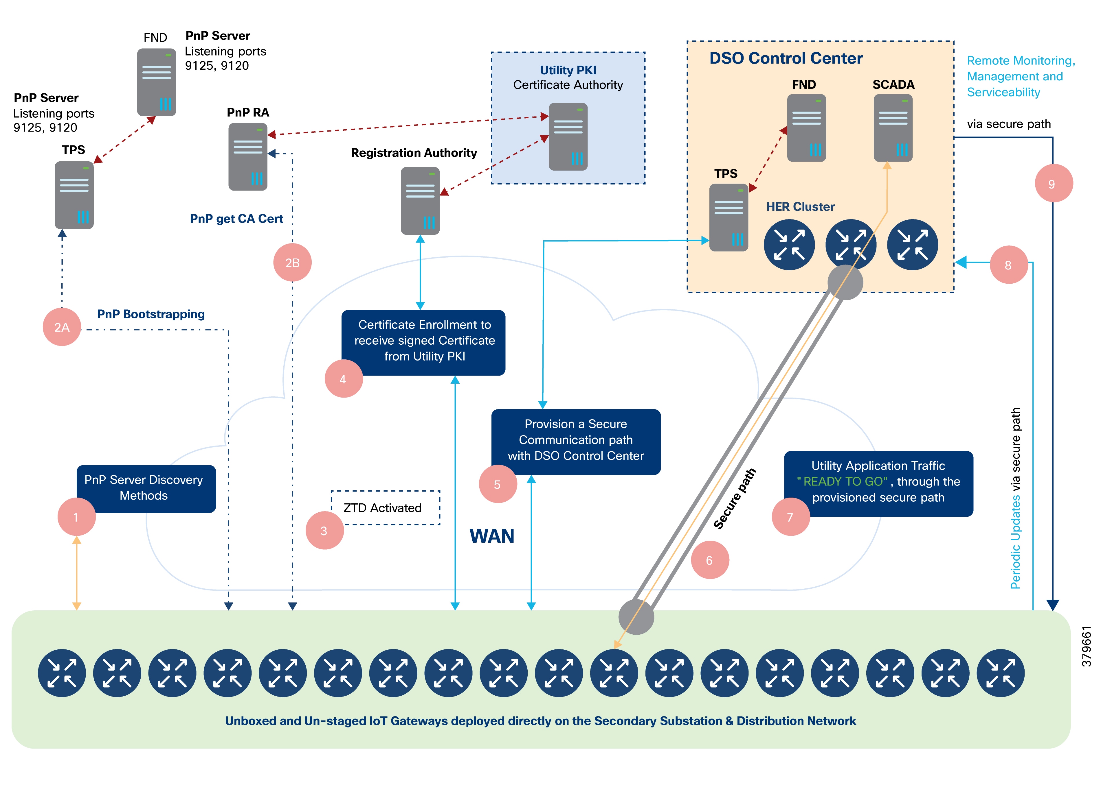
The illustration above logically captures the two different functionalities of TPS and Cisco IoT FND:
● PnP functionality of TPS and Cisco IoT FND
● ZTD functionality of TPS and Cisco IoT FND
To cater to the PnP bootstrapping functionality of TPS and Cisco IoT FND:
● FND (serving as PnP server) hosts the router bootstrapping template
● TPS serves as PnP proxy for the PnP server
● PnP proxy relays the communication between Cisco IoT gateways and the Cisco IoT FND.
To cater to the ZTD functionality of TPS and Cisco IoT FND:
● FND (serving as NMS server) hosts:
◦ Tunnel provisioning template
◦ Device configuration template
● TPS, acting as proxy for Cisco IoT FND, helps provision the secure tunnel connecting Cisco IoT gateways with the DSO Control Center.
Note: PnP and ZTD functionalities could both be served by the same pair of TPS/FND. However, you can also host the first pair of TPS/FND exclusively for PnP Bootstrapping, and the second pair of TPS/FND exclusively for ZTD functionality.
Recommended PnP Server Discovery Mechanisms
The selection of the appropriate PnP server discovery mechanism depends on whether the utility has control (or an agreement with the service provider) over WAN IP address assignment for Cisco IoT gateways, or the ability to add name resolution entries.
For deployments where bootstrapping occurs directly at the deployment location and the Cisco IoT gateway has Internet access, the most suitable discovery method is:
● PnP server discovery through Cisco PnP Connect (Cloud Redirection Service)
This method is particularly recommended when Cisco IoT gateways use LTE as the backhaul network, since Internet connectivity is typically available to reach devicehelper.cisco.com and obtain the PnP proxy/server information.
If the backhaul network is Ethernet, alternative discovery methods may be appropriate:
● PnP server discovery through DHCP server
Use this method if the utility controls or has an agreement regarding IP address allocation to the WAN interface via DHCP.
● PnP server discovery through DNS server
Use this method if the utility manages the DNS process and can configure the required name resolution entries.
Actors Involved in PnP and Their Roles
The following tables list the mandatory and optional actors for each PnP bootstrapping method, along with their roles and descriptions.
Table 19. Actors in PnP staging
| PnP Actors |
Role and description |
| PnP Agent |
This is a mandatory component that is embedded in Cisco devices in the latest IOS releases. In the PnP discovery process:
● The
PnP
agent
obtains
the
FQDN
or
IP
address of
the
PnP
server
(or
proxy).
● After
the
PnP
server
is
discovered,
the
PnP
agent
communicates
with the
PnP
server
(or
proxy)
to
perform
the
bootstrapping
operation.
● PnP
discovery
kicks
in
only
if
the startup configuration is not present on the device
(router).
PnP agent on the IoT Gateway must support the following PnP services:
● Certificate Install
Service
◦ Needed for Cisco IoT FND to manage trust points and certificate-related operations on the IoT Gateway.
● File
Transfer Service:
◦ Needed for Cisco IoT FND to push the configuration and ODM files to the IoT Gateway.
● CLI - Exec
Service:
◦ Needed for Cisco IoT FND to run show commands on the IoT Gateway.
● CLI - Configuration
Service:
◦ Needed for Cisco IoT FND to configure on the IoT Gateway. PnP discovery is terminated if any keystroke is detected on the console. |
| PnP Proxy (TPS) |
TPS, typically positioned in the DMZ, is a stateless extension of Cisco IoT FND that is meant for processing requests from an unsecure part of the network. TPS acts as a PnP proxy and then proxies the received PnP communication to the actual PnP server (Cisco IoT FND). The TPS is an optional, but highly recommended, component. In the absence of TPS, Cisco IoT FND component is exposed to the unsecure part of the network. TPS listens on the following network ports for communication:
● Port 9125 to process the initial communication
over
http.
● Port
9120
to
process
the
further
communication
over
https.
(Note:
For
communication
over https
to
work
on
port
9120,
the
device
must
have
certificate
and
a
common
trust
point).
● The CISCO ACT2 SUDI CA certificate is installed as a trust point on TPS to handle the https communication
from
IoT
Gateways
that
presents
its
unique
“CISCO_IDEVID_SUDI”
certificate during SSL/TLS
negotiation.
● Similarly,
the
trust
point
of
the
“TPS/FND”
is
installed
(automatically
during
bootstrapping)
on the Cisco IoT gateways to trust the certificate presented
by the TPS, during the HTTPS communication.
|
| PnP Server (Cisco IoT FND) |
This is a mandatory component. Cisco IoT FND acts as a PnP server and resides in the secure part of the network, typically in the data center. PnP server processes the communication from the PnP Proxy. PnP server is responsible for provisioning the Day 0 configuration on the IoT Gateway. The required Day 0 configuration could be defined as a bootstrapping template in Cisco IoT FND. Similar to TPS, the Cisco ACT2 SUDI CA certificate should be installed as trusted CA on Cisco IoT FND. |
| DHCP Server |
Mandatory actor if the chosen staging method is DHCP server-assisted PnP provisioning or DNS server-assisted PnP provisioning. Otherwise, this is an optional actor. Helps the Cisco device discover the PnP server by advertising the server-related information as part of the DHCP options. If TPS is used, the TPS address should be advertised as the PnP server address. For bootstrapping device over IPv4 backhaul using FQDN:
● DHCP
server
should
advertise
DHCP
vendor-specific
option
43,
delivering
the
ASCII
string.
● Sample ASCII String format:
5A;K4;B1;Itps-san.ipg.cisco.com;J9125
For bootstrapping device over IPv4 backhaul using IP address:
● DHCP
server
should
advertise
DHCP
vendor-specific
option
43,
delivering
the
ASCII
string.
● Sample ASCII String format:
5A;K4;B2;I172.16.242.2;J9125
For bootstrapping device over IPv6 backhaul:
● DHCP
server
should
advertise
DHCP
vendor-specific
option
9,
along
with
the
following sub-options:
◦ sub-option 16 for ciscopnp ◦ sub-option 17 for the ASCII string
● Sample ASCII string format:
5A1N;K4;B1;Itps-san.ipg.cisco.com;J9125
Notes:
● This
DHCP
server
is
only
from
the
bootstrapping
context.
There may be another
DHCP
server
that allocates the WAN IP address during deployment on the Cisco IoT
gateway.
● The
device
could
be
bootstrapped
using
DHCP- server-assisted
PnP
provisioning,
and
the deployment could happen
over LTE/Ethernet/any other backhaul network
type.
● This
option
might
not
be
applicable
for
the
devices
bootstrapping
over
cellular
network,
as
the IP address allocation mechanism used is IP Control Protocol
(IPCP).
|
| DNS Server |
Mandatory actor if the chosen staging method is DNS server-assisted PnP provisioning. In sequence, DHCP server would advertise the IP address along with DNS server IP and domain name (for example, domain.com). Cisco IoT Gateway, upon receiving the IP address, gateway, and DNS server details, sends a DNS resolution request for pnpserver.domain.com. DNS server helps resolve the FQDN pnpserver.domain.com to IP address of the PnP server. Recommendations:
●
pnpserver.domain.com should
resolve
to
PnP
Proxy's
IP
address, if TPS is involved
●
pnpserver.domain.com should
resolve
to
PnP
Server's
IP
address,
if only Cisco IoT FND is used
DNS: A record is created if the staging network uses IPv4. DNS: AAAA record is created if the staging network uses IPv6. |
| Cisco PnP Connect (or) Cloud Redirection Server |
Mandatory actor if the chosen staging method is Cisco PnP Cloud Redirection Service-assisted provisioning The following data must be defined in Cisco Software Central, in Network Plug and Play:
● Controller
profile
must
be
defined
with
the
IP or FQDN
detail,
as
well
as
desired
port number of the PnP Proxy
server.
● Devices must be added to the portal and linked to the controller
profile.
As part of PnP server discovery, when the IoT Gateway reaches out to devicehelper.cisco.com, the portal would send the PnP redirect information to the device. Then, the PnP profile is automatically installed on the router. The PnP redirect information includes the FQDN or IP address of the PnP Proxy along with the port number on which the router must communicate to complete the bootstrapping the router. |
Roles of PnP Actors in each PnP Server Discovery Method—Summary Matrix
Table 20. Plug-and-Play actors in various PnP server discovery methods
| PnP Discovery Process |
PnP Agent on Cisco Routers |
PnP Proxy (TPS) |
PnP Server (Cisco IoT FND) |
DHCP Server |
DNS Server |
Cisco Cloud Redirection Server |
| DHCP server-assisted PnP Provisioning |
Yes |
Highly Preferred |
Mandatory |
Mandatory. Vendor Specific Options advertise PnP server details. |
Needed if the DHCP VSO advertises an FQDN instead of an IP address. |
N/A |
| DNS server-assisted PnP Provisioning |
Yes |
Highly Preferred |
Mandatory |
● Advertises:
IP address + domain
name + DNS
server
● PnP server information not provided by DHCP
|
Mandatory PnP server details provided while resolving PNP server FQDN. |
N/A |
| Cisco Cloud Redirection server-assisted PnP provisioning |
Yes |
Highly Preferred |
Mandatory |
● PnP server information not provided by DHCP
● Not applicable for LTE network type.
|
● Required to resolve the Cisco Cloud redirection server.
● PnP server information not provided by DNS.
|
● Should have public reachability to the Cisco Cloud Redirection server.
● Provides PnP server information.
|
| Custom Profile Configuration- assisted PnP provisioning (PnP server detail manually configured) |
Yes. |
Highly Preferred. |
Mandatory |
Optional.
● Advertises IP address
along with DNS server
details.
● Not
applicable for
LTE network
type.
|
Optional. Needed only if custom PnP server profile references FQDN. |
N/A |
The TPS functions as a stateless extension of the Cisco IoT FND, designed to handle requests from the untrusted segments of the network. Typically deployed in the DMZ, TPS is essential in scenarios where direct exposure of FND to the untrusted network is not advisable. TPS receives communications from the untrusted network and securely proxies them to the FND, which resides in the trusted zone.
Note: Without TPS, Cisco IoT FND components would be exposed directly to the untrusted part of the network, which is not recommended for security reasons.
During PnP bootstrapping, TPS can act as the PnP Proxy for the PnP Server (Cisco IoT FND). If a bootstrapping request arrives on a custom port (other than the default port 9125), TPS can be configured to listen on that custom port and forward the communication to FND on port 9125.
As the PnP Proxy, TPS acts as the server for the PnP agent on the IoT Gateway—receiving communications from the agent and relaying them to the actual PnP Server (FND). For example, if the PnP agent communicates on port 80 instead of port 9125, TPS can listen on port 80 and then forward the request to FND on port 9125. This allows PnP bootstrapping to operate over non-default ports while FND continues to listen on its default port.
Notes:
● TPS (as a PnP Proxy) is highly recommended for all bootstrapping scenarios that traverse the WAN or Internet to reach the PnP server.
● TPS (as a Tunnel Proxy Server) is also highly recommended for all ZTD scenarios.
However, in a controlled staging environment with a private local network, Cisco IoT FND can be directly connected to the local network and made available for IoT Gateway bootstrapping, making the TPS Proxy optional in such cases.
TPS Proxy serves two key roles during ZTD:
● As the PnP Proxy for Day 0 configuration provisioning (bootstrapping).
● As the Tunnel Proxy Server for tunnel provisioning in ZTD.
Table 21. Use of PnP proxy in various bootstrapping methods
| Platform |
PnP Proxy |
Is PnP Proxy Mandatory? |
Can ZTD TPS be the same as PnP Proxy TPS? |
| Bootstrapping in local staging network |
Optional component. If used, the scope of the PnP Proxy is limited to local staging network. |
Not if the local staging network is a controlled private network. PnP Server (Cisco IoT FND) could be used directly for bootstrapping, without using TPS PnP Proxy. Exposing Cisco IoT FND is typically acceptable in controlled private local networks. |
No, because the staging environment is local. ZTD TPS is reachable over Internet/WAN. However, TPS Proxy is optional in private local staging networks. |
| Bootstrapping in distributed staging network |
● Resides in DMZ.
● Faces untrusted
WAN on southbound.
● Faces trusted network on northbound connecting
to PnP server
(Cisco IoT FND).
|
Mandatory PnP proxy could cater to bootstrapping requests from the IoT Gateways located in local staging network as well as from multiple distributed staging sites |
Yes. TPS/FND located in DSO Control Center could be used for both:
● Bootstrapping of IoT Gateways from multiple distributed staging
sites.
●
Tunnel
Provisioning.
|
| Bootstrapping straight out of deployment location |
● Resides in DMZ.
● Faces untrusted
WAN on southbound.
● Faces trusted network on northbound connecting
to PnP server
(Cisco IoT FND).
|
Mandatory. PnP proxy could cater to bootstrapping requests from IoT Gateways reachable from anywhere over the WAN/Internet. |
Yes. Same TPS/FND located in DSO Control center could be used for both bootstrapping and tunnel Provisioning. |
To enable HTTPS communication between Cisco IoT gateways and the PnP proxy or server, the proxy or server must present a server certificate that establishes its identity to the gateways.
For successful PnP server discovery on Cisco devices running recent IOS-XE releases, the SSL certificate presented by the PnP proxy or server during the handshake must include the appropriate Subject Alternate Name (SAN) value. This allows the Cisco Plug and Play Agent to verify the server's identity.
Administrators may need to upload new SSL certificates containing the correct SAN values into the TPS and FND keystores.
Key notes:
● If a SAN or DNS name (FQDN) is used in the TPS or Cisco IoT FND certificate, it is recommended to use the FQDN consistently throughout the configuration.
● If a SAN/IPv4 address is used in the certificate, use the IPv4 address everywhere.
● If a SAN/IPv6 address is used in the certificate, use the IPv6 address everywhere.
Certificate Considerations for PnP and ZTD
The following table outlines sample certificate parameter requirements for TPS/FND.
Table 22. Certificate considerations for PnP and ZTD
| Certificate Properties |
For TPS Bootstrapping |
For Cisco IoT FND Bootstrapping |
For ZTD, with TPS |
For ZTD, with Cisco IoT FND |
| Common Name Requirement |
N/A |
N/A |
tps.ipg.cisco.com |
fnd.ipg.cisco.com |
| Subject Alternate Name requirement (FQDN) |
tps.ipg.cisco.com |
fnd.ipg.cisco.com |
N/A |
N/A |
| Subject Alternate Name requirement (IPv4) |
10.10.242.242 |
172.16.103.100 192.168.103.100 |
N/A |
N/A |
| Subject Alternate Name requirement (IPv6) |
2001:db8:10:242::242 |
2001:db8:16:103::100 |
N/A |
N/A |
Example 1: Bootstrapping with SAN/DNS (FQDN)
If the FQDN (e.g., tps.ipg.cisco.com) resolves to an IP address, use the following certificate parameters:
TPS certificate:
CN="tps.ipg.cisco.com"
O="Cisco Systems Inc"
SAN/DNS="tps.ipg.cisco.com"
FND certificate:
CN="fnd.ipg.cisco.com"
O="Cisco Systems Inc"
SAN/DNS="fnd.ipg.cisco.com"
Example 2: Bootstrapping with SAN IPv4
If the FQDN is not resolvable, use the IPv4 address in the SAN:
TPS certificate:
CN="tps.ipg.cisco.com"
O="Cisco Systems Inc"
SAN/IPv4="10.10.242.242"
FND certificate:
CN="fnd.ipg.cisco.com"
O="Cisco Systems Inc"
SAN/IPv4="172.16.103.100"
SAN/IPv4="192.168.103.100"
Example 3: Bootstrapping with SAN DNS and IPv4
For bootstrapping over FQDN or IPv4:
TPS certificate:
CN="tps.ipg.cisco.com"
O="Cisco Systems Inc"
SAN/IPv4="10.10.242.242"
SAN/DNS="tps.ipg.cisco.com"
FND certificate:
CN="fnd.ipg.cisco.com"
O="Cisco Systems Inc"
SAN/IPv4="172.16.103.100"
SAN/IPv4="192.168.103.100"
SAN/DNS="fnd.ipg.cisco.com"
Example 4: Bootstrapping with SAN DNS and IPv6
For bootstrapping over FQDN or IPv6:
TPS certificate:
CN="tps.ipg.cisco.com"
O="Cisco Systems Inc"
SAN/IPv6="2001:db8:10:242::242"
SAN/DNS="tps.ipg.cisco.com"
FND certificate:
CN="fnd.ipg.cisco.com"
O="Cisco Systems Inc"
SAN/IPv6="2001:db8:16:103::100
SAN/DNS="fnd.ipg.cisco.com"
Important Notes:
The SAN in the TPS and FND certificates should include the FQDN (and optionally the corresponding IP addresses).
The Common Name (CN) must match the FQDN used in the URL during HTTPS communication from the IoT Gateways.
During ZTD, ensure that the CN in the certificates matches the FQDN used in the HTTPS URL from the IoT Gateways.
For example, to access https://tps-san.ipg.cisco.com:9120, the CN must match tps-san.ipg.cisco.com.
Any attempt to access https://10.10.242.242:9120 with a certificate that only includes an FQDN in the CN, results in SSL connection failure.
Considerations for Cellular Backhaul (Private APN vs. Public APN)
Public Cellular Service
Public cellular service typically provides internet connectivity and dynamic IP address assignment. Cisco modems are preloaded with firmware and default profiles for each service provider, making onboarding fully automated and user-friendly.
Recommended PnP discovery: PnP Connect.
Advantages: Pre-configured APN, dynamic IP assignment, and ready for server discovery through PnP Connect.
Private Cellular Service
With private cellular services, the customer APN must be configured on the modem (not on the router) to ensure it persists through reboots. This service may or may not include internet connectivity.
With Internet: Recommended PnP discovery is PnP Connect.
Without Internet: Use DNS server-based discovery or manual profile. In this case, TPS must be reachable over the private cellular network.
Network Management System (NMS)
The Network Management System (NMS), known as the Field Network Director (FND), resides in the communication headend. FND is a software platform that manages the multi-service network and security infrastructure for IoT applications in Distribution Automation.
Bootstrapping and Zero Touch Deployment
FND serves as the PnP server for bootstrapping and assists with ZTD of Cisco IR1101 routers, as previously described.
After Zero Touch Deployment, the IoT Gateway:
● Is securely connected to FND, enabling SCADA and other application traffic.
● Periodically updates FND with operational status.
Key serviceability features in FND include:
Remotely monitor IoT Gateways from FND, including:
● Cellular RSSI (signal strength)
● Cellular link traffic statistics
● Event and issue alerts
● Historical state summaries for multiple gateways (e.g., Up, Down, Unheard)
● Inventory and health details (uptime, interface status, metrics like RSRP/RSRQ/SNR, traffic speed, drops)
● Location tracking
Remotely manage IoT Gateways from FND, including:
● Remote deployment and management
● Seamless upgrades from Serial to IP controllers
● Group firmware upgrades
● Remote configuration changes for application traffic, raw-socket, protocol translation, IPv4/IPv6 communication, secondary control center connectivity, and QoS policies
● Remotely enabling DHCP and NAT/PAT services for IEDs
● Reprovisioning backhaul between Ethernet/Cellular or between cellular providers
● Enabling/disabling secondary backhaul from FND
Facilitating Controller Device Upgrades
When controller devices are upgraded or replaced, the IoT Gateway may require interface or protocol changes (e.g., Serial to Ethernet, IPv4 to IPv6, protocol migrations). FND enables these remote modifications to ensure seamless operation.
IoT Gateway Edge Compute Application Lifecycle Management
IoT Gateways with edge compute capabilities can host custom applications. Utility customers can use FND to remotely manage the lifecycle of these edge applications on deployed gateways.
FND provides remote troubleshooting and recovery tools, such as:
● Ping and traceroute for connectivity tests
● On-demand metric refresh
● Remote reboot capability
For more information, see IoT Field Network Director User Guide, Release 5.0.
Cisco IoT FND typically resides in the Utility Control Center alongside other utility headend systems. It supports Northbound APIs for integration with utility operational platforms and manager-of-manager systems.
Cisco IoT FND maintains a database of device inventory, groups, properties, metrics, and events.
The NB API (SOAP-based) provides:
● Read-only access to Cisco IoT FND’s database
● Push-based event reporting over HTTPS
Northbound API clients must subscribe by providing a valid HTTPS URL. FND accepts all SSL certificates from the northbound API client when establishing secure connections.
For more information, see the North Bound API User Guide for Cisco IoT Field Network Director.
Security, High Availability, and Scale
This chapter addresses the following key areas:
● Security
● High Availability
● Scale
For comprehensive security of Cisco IR routers, refer to the Cisco Guide to Harden Cisco IOS Devices guide.
Security Management in the Secondary Substation
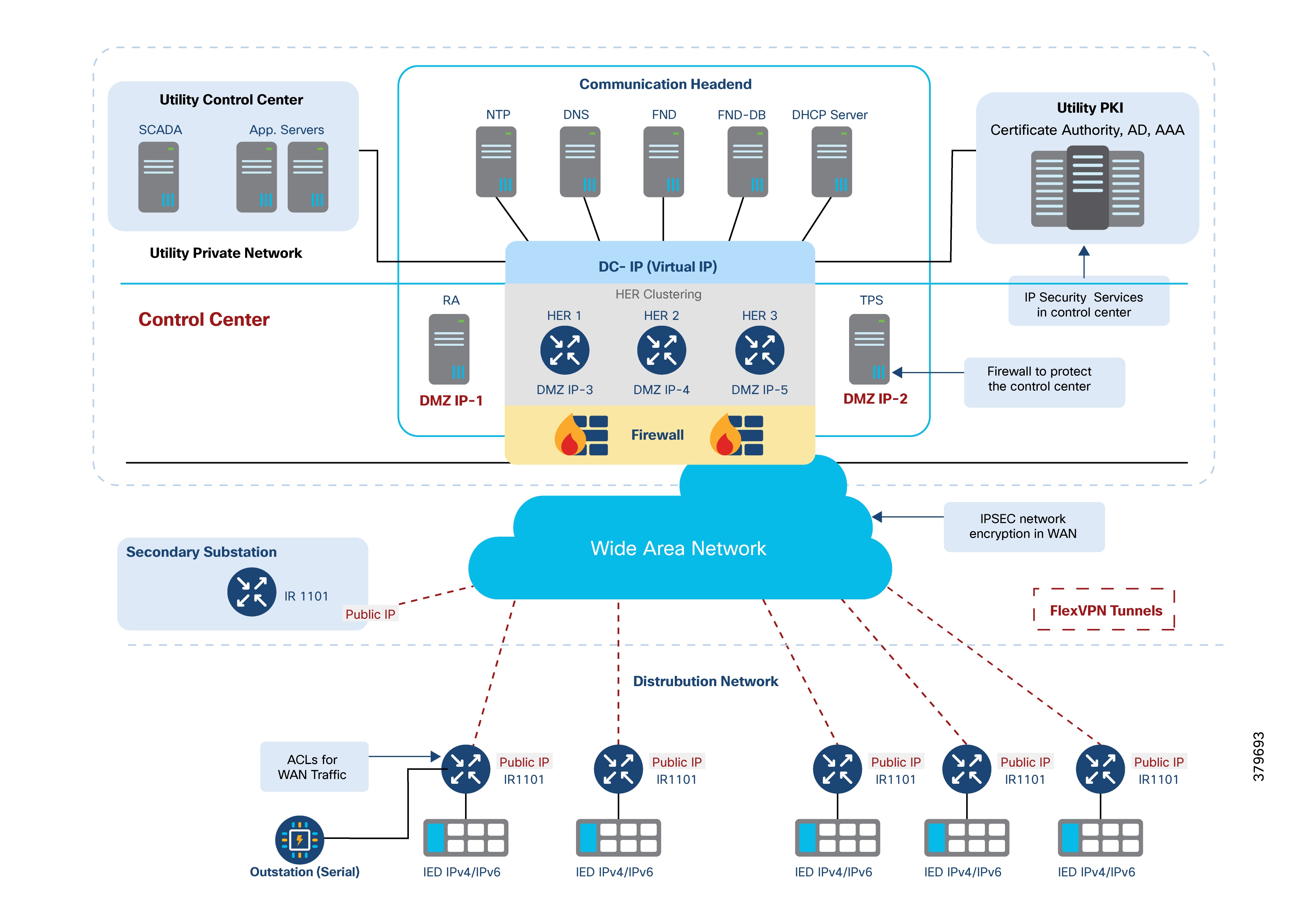
Security across the layers is a critical aspect of the Distribution Automation solution architecture. Cisco DA solutions provide critical infrastructure-grade security for controlling access to critical utility assets, monitoring the network, mitigating threats, and protecting grid facilities.
The solutions enhance overall network functionality while simultaneously making security easier and less costly to manage.
● Security principles governing the architecture include:
● Preventing unauthorized access to head-end systems
● Protecting SSRs and DA Gateways from cyber-attacks
● Identifying and mitigating security threats
● Meeting regulatory requirements
● Maximizing visibility into network environments, devices, and events
● Applying security policies to both IPv4 and IPv6, given dual-stack operation
● Preventing unauthorized configuration changes or data tampering on field area routers
● Containing malware to prevent disruption of the solution
● Segregating network traffic to protect mission-critical data in a multi-service DA environment
● Ensuring QoS for critical data flows and policing potential DoS traffic
● Real-time monitoring for immediate threat response
● Efficient deployment and management of network security services for DA Gateways
All utility facilities, assets, and data must be protected through robust user authentication and access control. Strong identity mechanisms are required for users, devices, and applications. Mutual authentication between communication nodes is essential for security.
Authentication, Authorization, and Accounting (AAA)
AAA functions require a scalable, high-performance policy system at the DSO Control Center, supporting centralized authentication and access management. RADIUS is recommended as the primary protocol for centralized AAA. TACACS+ may be used for command authorization on DA Gateways and SSRs.
Certificate-Based Authentication
Cisco IR1101 routers are shipped with an X.509-based device identity certificate (IdevID), which can be used for initial bootstrapping and replaced by a utility-specific certificate (LDevID) via SCEP. This certificate forms the foundation for AAA with other network elements, such as meters, routers, NMS, and authentication servers.
RSA is recommended for authentication, and certificates should have a five-year lifespan.
The DA gateways that support RSA include HERs, Cisco IoT FND, TPS, and Cisco IR1101.
DA application traffic confidentiality is enforced using network-level encryption between the HER and DA Gateways/SSRs, leveraging Cisco FlexVPN. Detailed FlexVPN configuration guidance is provided in the Design Considerations section.
Logical separation of network functions (for example, smart meters vs. DA devices) is enforced using VLANs, GRE tunnels, access lists, and firewalls to prevent unauthorized communication and limit malware spread.
See the IP Address Schema section for VLAN design guidance.
All traffic from SSRs and DA Gateways to the control center must traverse a high-performance firewall, especially if originating from public networks. The firewall should be configured in transparent mode, with zone-based policies and protection against advanced threats. The HER-facing interface is “inside” and the WAN-facing interface is “outside.” Deploy firewalls in pairs for redundancy.
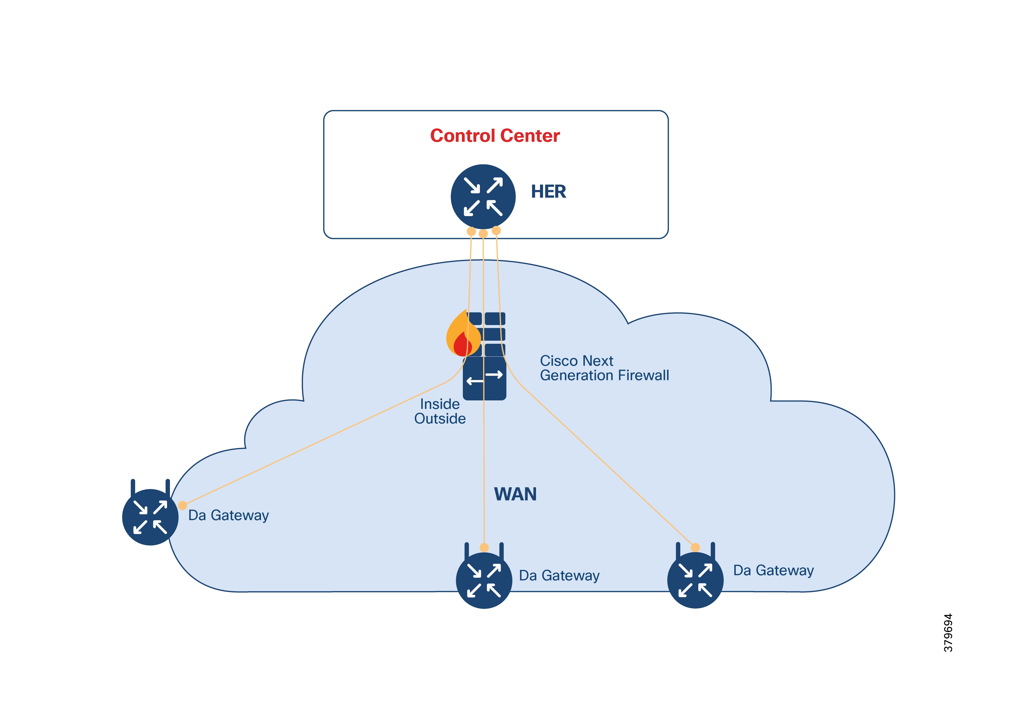
Firewall configuration guidelines:
1. Configure ACLs to permit necessary traffic between DA Gateways and the HER at the ASA.
2. Assign security levels:
3. Outside (NAN-facing): 0
4. Inside (headend-facing): 100
Table 23. Firewall ports to be enabled for AMI
| Application or device |
Protocol |
Port |
Port Status |
Service |
Exposed |
ASA interface |
| TPS |
TCP |
9120 |
Listening |
CGR tunnel provisioning HTTPS |
FAN |
Outside |
| Registration Authority |
TCP |
80 |
Used |
HTTP for SCEP |
FAN |
Outside |
| HER |
UDP |
123 |
Used |
NTP |
FAN |
Outside |
| HER |
ESP |
- |
Used |
IP protocol 50 |
FAN |
Outside |
| - |
UDP |
500 |
Used |
IKE |
Both |
Outside/Inside |
| - |
UDP |
4500 |
Used |
NAT traversal (if any) |
Both |
Outside/Inside |
Redundancy is integrated at multiple levels:
IR1101 devices, acting as FlexVPN spokes (with single or dual backhaul), connect to a cluster of Catalyst 8500 routers (HERs) supporting multi-hub scenarios. Up to 50,000 IR1101s can be aggregated with six or seven C8500-12X routers. FlexVPN tunnels can carry both IPv4 and IPv6 traffic, including multicast. Routing can be managed via IKEv2 prefix injection (preferred) or dynamic protocols like MP-BGP.
HER redundancy leverages FlexVPN Cluster Load Balancing (CLB), which uses IKEv2 redirection (RFC 5685) to redirect spokes to the least loaded gateway within an HSRP cluster. Failover is automatic: if the Master fails, a Slave takes over. Configuration details for CLB are available here.
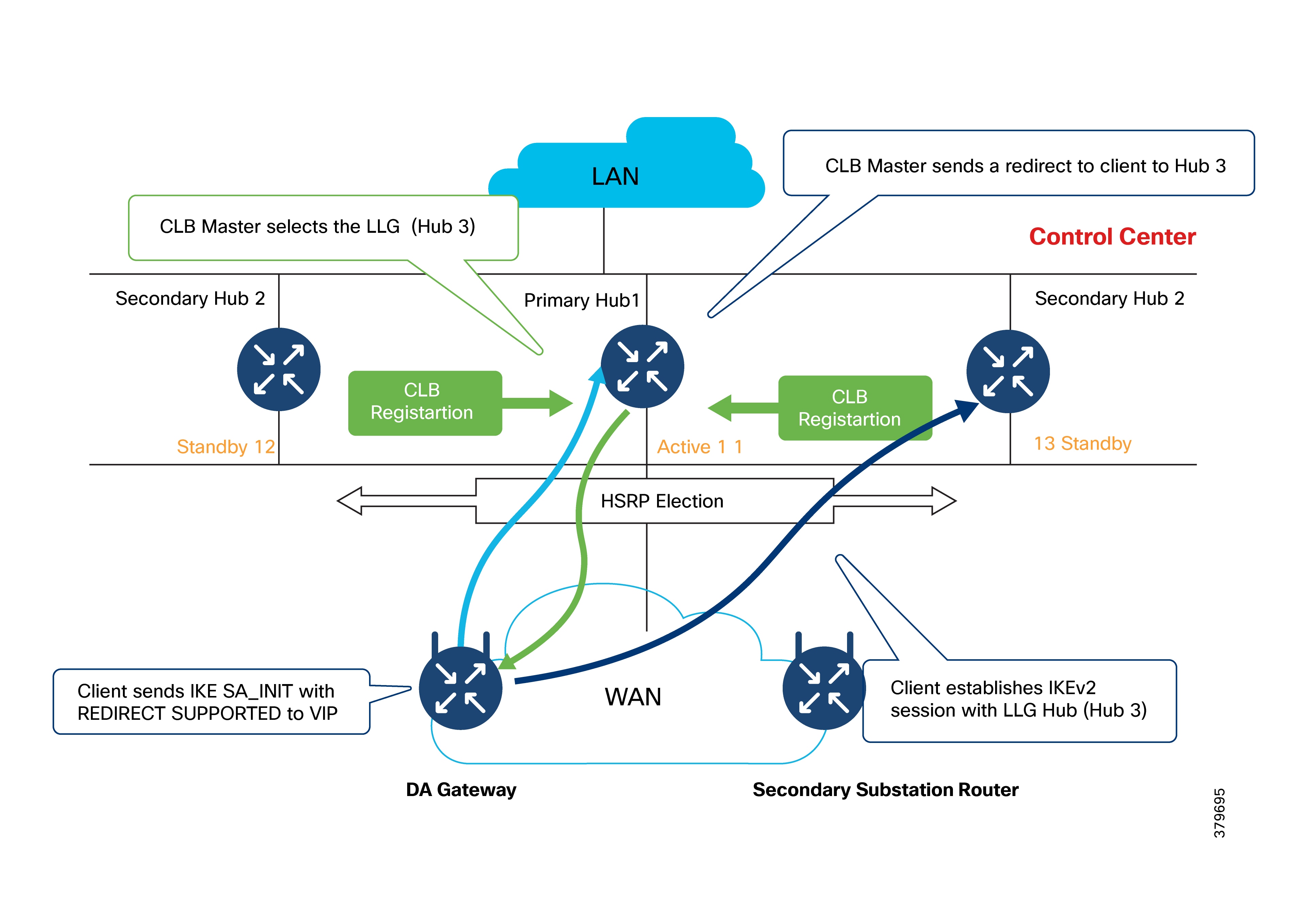
SSRs/DA Gateways can be deployed with dual backhaul interfaces (cellular and/or Ethernet), providing multiple redundancy options:
Option 1: Single FlexVPN tunnel pivoting across dual interfaces (dual ISP)
Option 2: Dual active FlexVPN tunnels (active/active, dual ISP)
Option 3: WAN backhaul redundancy using dual-LTE networks
Single Tunnel FlexVPN Tunnel Pivot
The single FlexVPN tunnel approach may leverage the IKEv2 Tunnel Pivot feature when configuring the FlexVPN client on the DA Gateway or SSR.
Each backhaul interface is up, but only one forwards traffic at a time. Primary interface is preferred for ZTD communications. IP SLA-based WAN monitoring detects failures and enables automatic failover.
For more on WAN monitoring, see the Cisco IR1101 Software Configuration Guide.
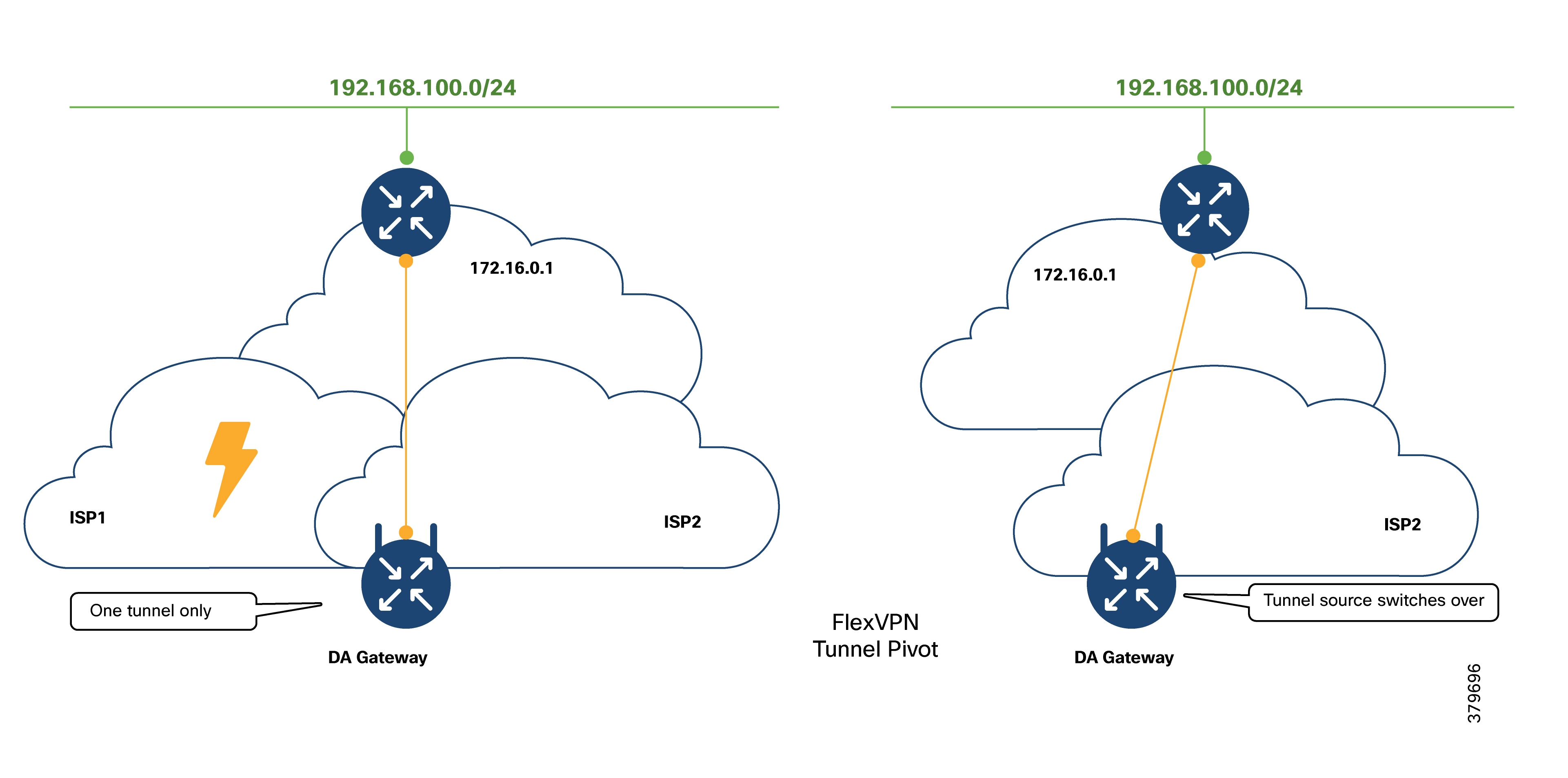
Double FlexVPN Tunnel
In this active/active design, two FlexVPN tunnels are established via different backhaul interfaces and ISPs, each terminating on a different HER. This allows for seamless dual backhaul and ISP failover, as well as control center redundancy. Maintaining two tunnels adds some configuration complexity but increases resiliency.
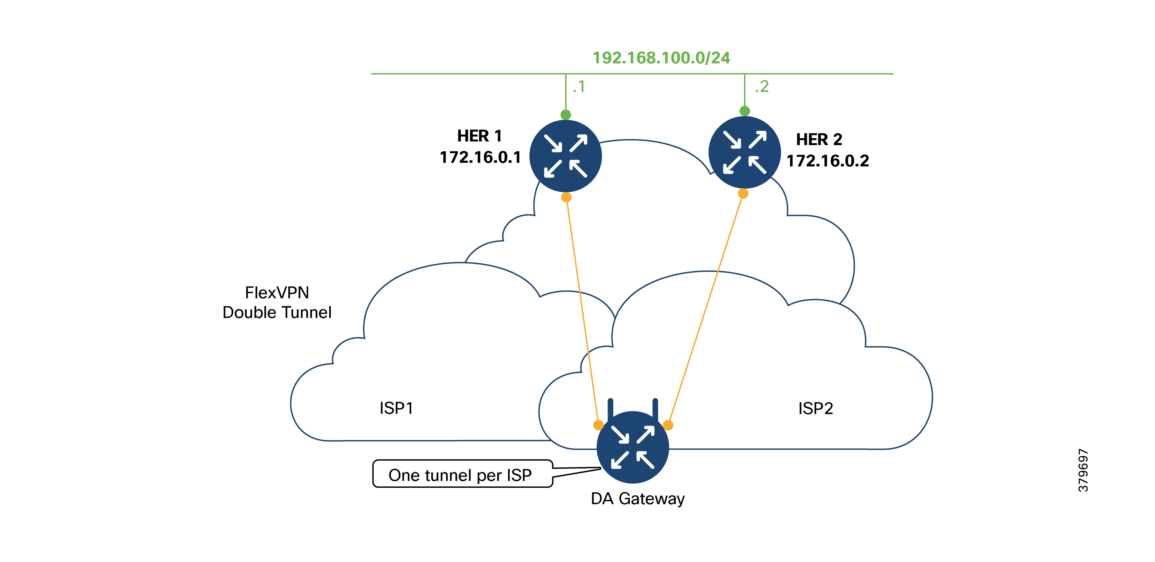
WAN Backhaul Redundancy with Dual-LTE Networks
IR1101 devices can be equipped with two LTE modules for true dual-LTE WAN redundancy, minimizing single points of failure. Key isolation requirements for dual-LTE deployments:
1. Maintain at least 46 dB radiated isolation between LTE module antennas.
2. Never mount both antennas on the chassis; separate their placement to ensure adequate isolation.
3. Isolation is required when using the same provider or overlapping frequency bands.
4. If frequency bands do not overlap, isolation may be reduced to 30 dB instead of 46 dB.
5. Isolation depends on antenna distance, frequency, radiation pattern, and surrounding objects.
6. Do not use RF attenuators to achieve isolation, as they reduce signal quality.
Dual LTE WAN Redundancy Scenarios
Table 24. Dual LTE interfaces on base and expansion modules
| Interface name |
Module type |
Description |
| Cellular0/1/X |
Base module |
● Used for PnP and
ZTD
● Serves as primary
LTE (or preferred
LTE)
● FlexVPN
Tunnel0
would
be
established
during
Tunnel
provisioning phase of ZTD
(over this base
module).
|
| Cellular0/3/X |
Expansion module |
● Serves as secondary
LTE
|
Three design options exist:
● Active/Standby-Shut: Only one radio is active at any time; the secondary is shut down until needed.
● Active/Standby-UP: Both radios are up, but only the primary is used for forwarding traffic. The secondary is ready for faster failover.
● Active/Active Load-Sharing: Both interfaces are up and used simultaneously for load sharing.
Table 25. Dual LTE scenarios comparison
| Dual LTE scenario |
Tunnel approach |
Primary LTE (initial state) |
Secondary LTE (initial state) |
Comments or descriptions |
| Active/Standby-Shut |
Single Tunnel |
Cellular0/10/0 is UP Tunnel) over it |
Cellular0/3/0 in shutdown state |
Traffic on Primary LTE only; if Primary fails, traffic resumes on Secondary LTE |
| Active/Standby-UP |
Single Tunnel |
80 |
Cellular0/3/0 in UP state, but not used when primary LTE is in use |
Traffic on Primary LTE only; if Primary fails, traffic resumes on Secondary LTE |
| Active/Active load-sharing scenario |
Two Tunnel |
|
Cellular0/3/0 in UP state. Actively used. Tunnel 1 over it. |
Destination-based load-sharing between Primary and Secondary LTE interfaces (read: via Tunnels) |
|
|
|
|
|
Tunnel0 and Tunnel1 terminate on two different HERs of the cluster. |
For each scenario, consider three operational states:
● Operational State: Normal operation (e.g., only primary is used in standby scenarios; both are used in active/active).
● Failover State: Transition when the primary interface fails.
● Recovery State: Return to normal once the failed interface recovers.
Active/Standby-Shut Scenario: Operational State
We have the IR1101 Cellular gateway with two cellular radios: one on the base module, the second on the expansion module. It is assumed that the isolation requirements are addressed with respect to antenna positioning.
FlexVPN Tunnel0 is established over primary LTE module of IR1101 and terminates on the HER cluster.
SCADA, Cisco IoT FND, and other control center and utility applications are advertised via Tunnel0.
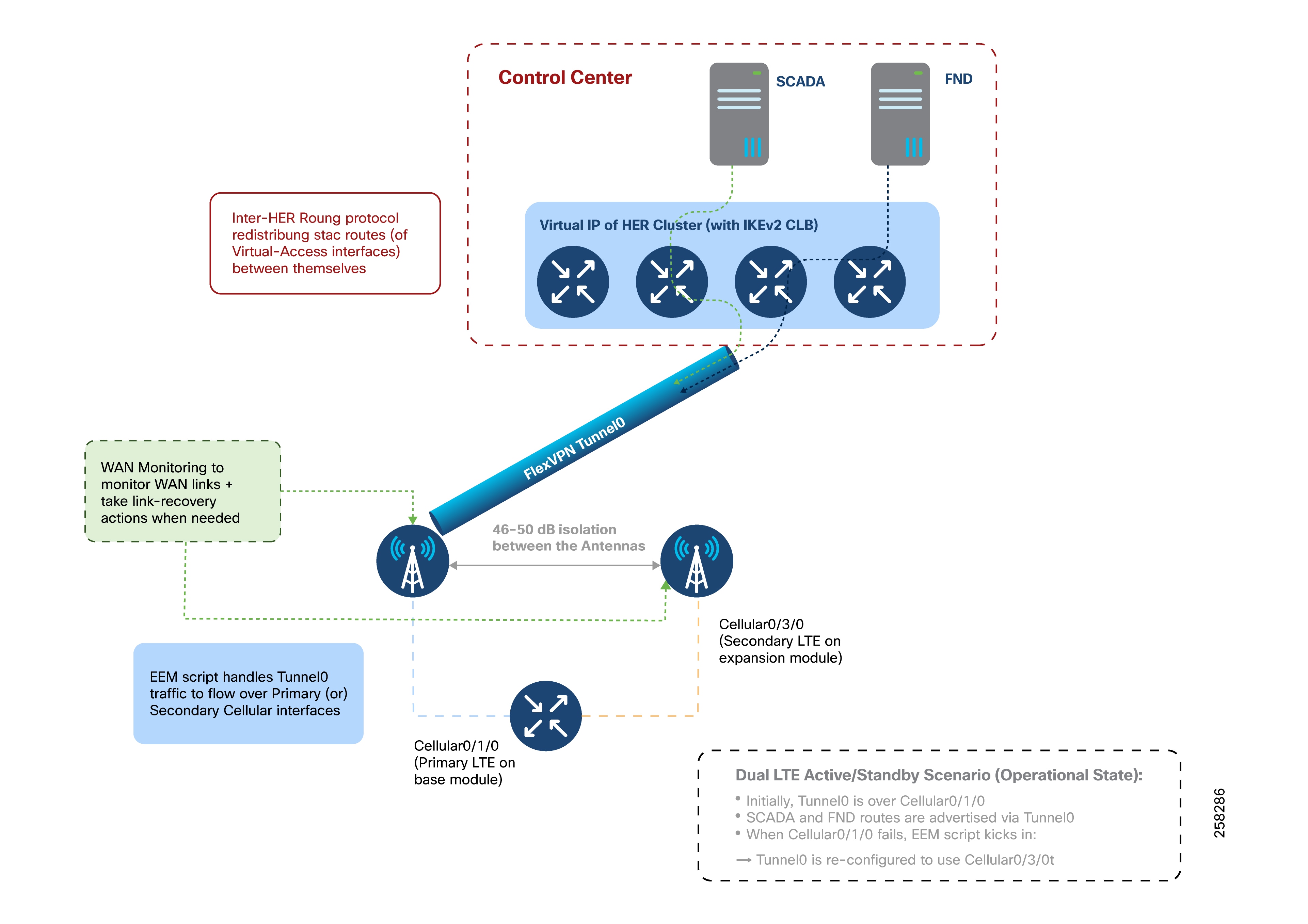
Requirement for Inter-HER Routing Protocol in Control Center:
Virtual Access interface on HER side corresponds to the the FlexVPN Tunnel0 interface on the IR1101. A routing protocol should be run between the HERs in the HER cluster, redistributing the virtual-access interfaces terminating on each HER.
The goal is to make all HERs aware of the FlexVPN tunnels terminating on all other HERs, and to enable consistent routing of return traffic via the appropriate HER.
The requirement of the Inter-HER routing protocol is common for all three Dual LTE scenarios.
Active/Standby-Shut Scenario: Failover State
Primary radio failure could be related to the radio or service provider.
An Embedded Event Manager (EEM) script detects the radio interface failure (or) connectivity failure (read as service provider failure) over the primary radio. Once detected, the FlexVPN tunnel is re-configured to use the secondary LTE radio.
Note: The scenario uses the single tunnel approach. Therefore, the FlexVPN tunnel is referred as Tunnel0.
At the same time, WAN Monitoring to monitor WAN links and to take link-recovery actions in case of WAN link failure.
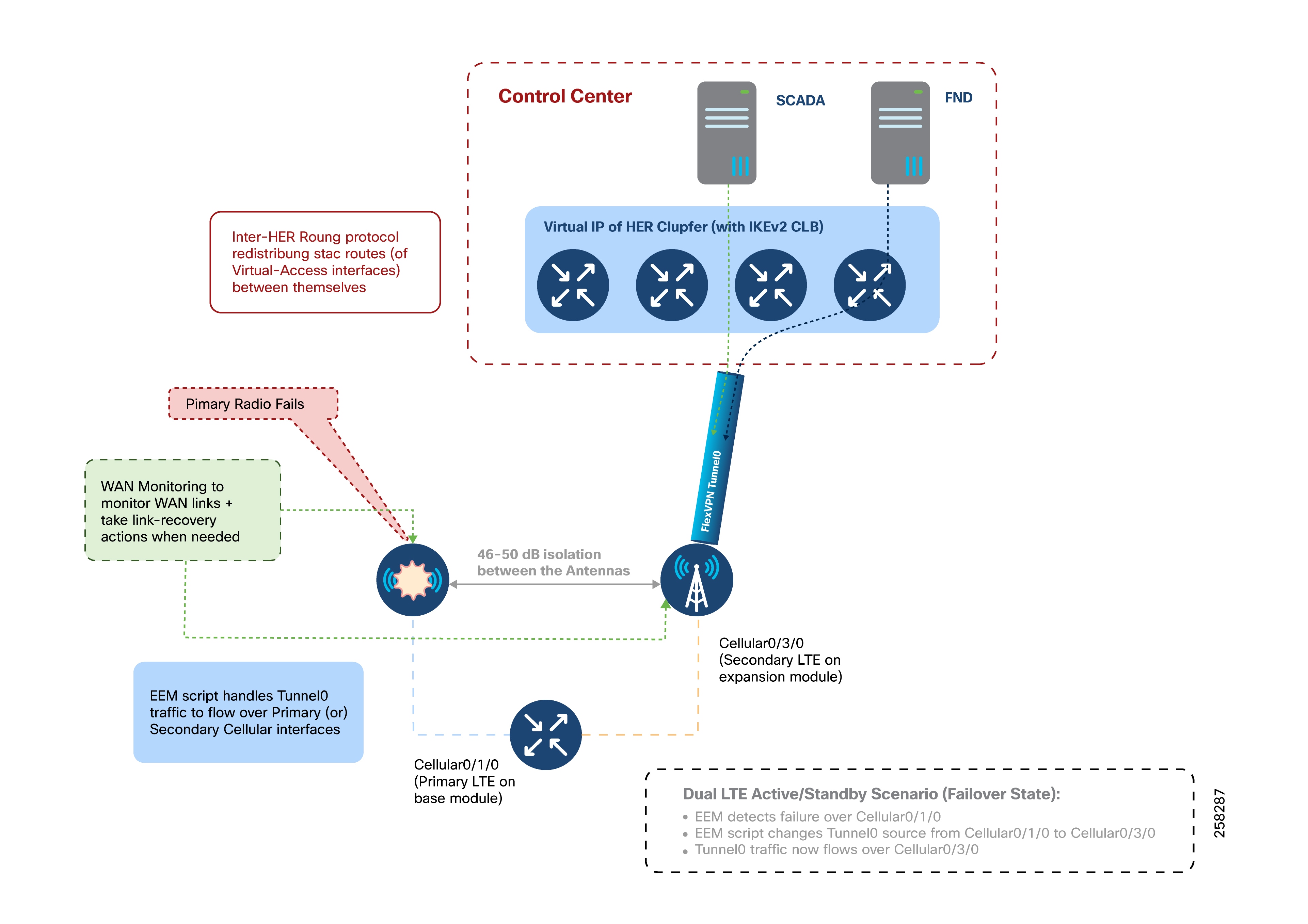
Active/Standby-Shut Scenario: Recovery State
As illustrated in Figure 65, when the primary radio recovers, the Embedded Event Manager (EEM) script detects that the primary LTE interface is operational. The script then waits for a predefined stabilization period (for example, 120 seconds) to confirm the interface remains stable. Once this waiting period is complete and the interface is confirmed to be up, the tunnel traffic is switched back to the primary LTE module.
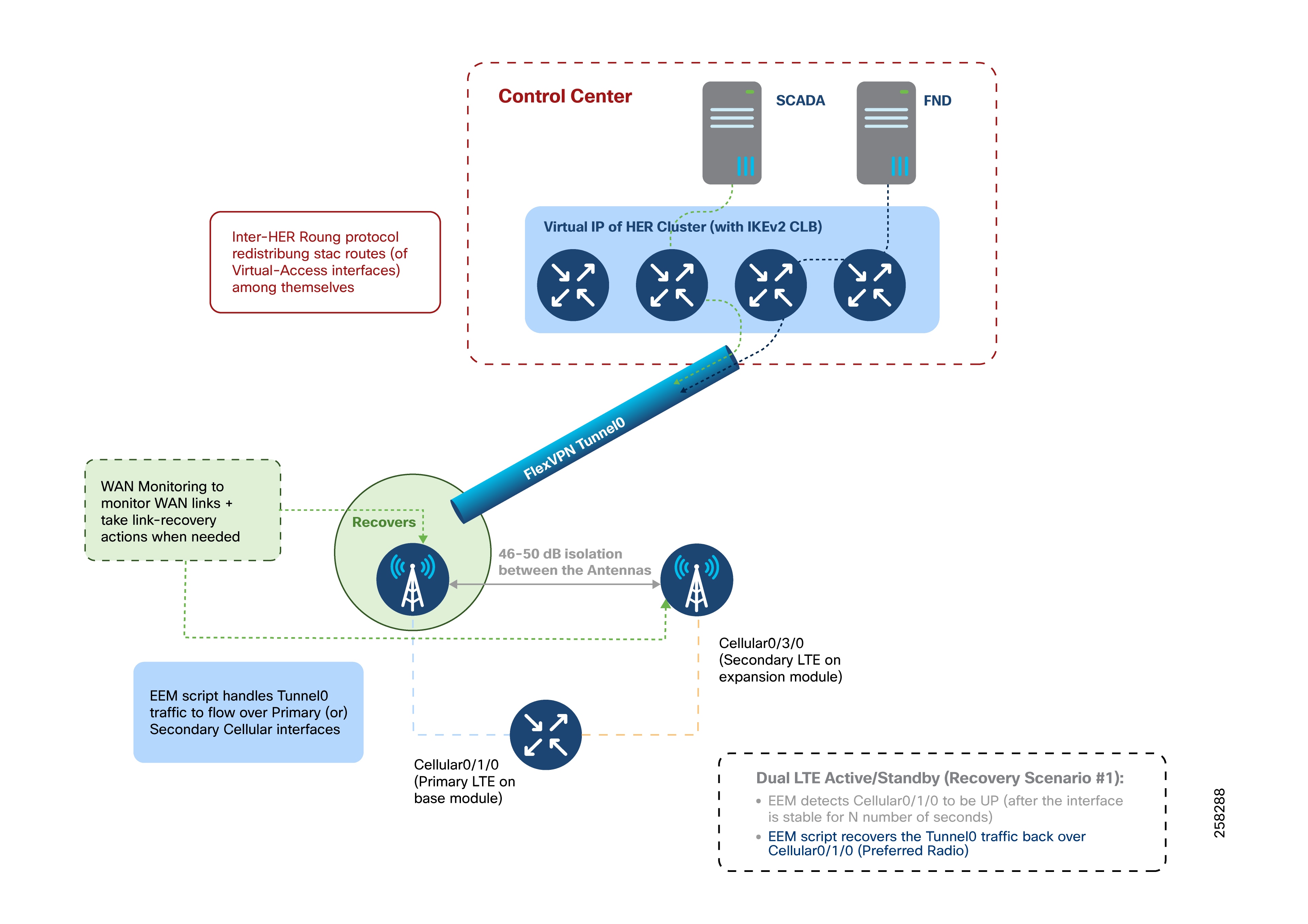
Active/Standby-Shut Scenario: Resiliency Life Cycle
The EEM script handles this resiliency life cycle, including the normal operational state, failover state, and recovery state.
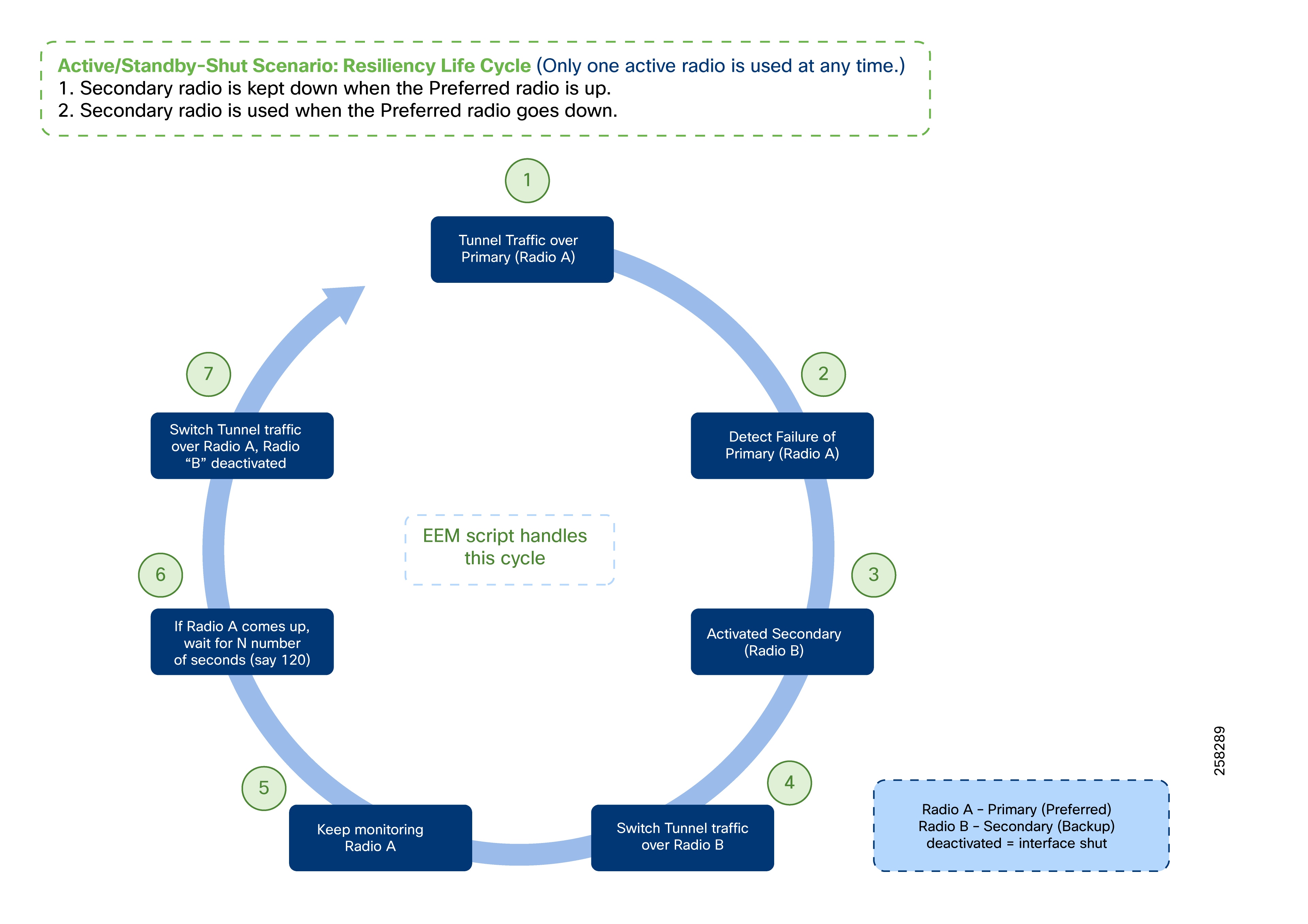
1. EEM script activates (no shut) the Secondary Radio B.
2. EEM script changes the tunnel source to switch the Tunnel traffic over the Secondary Radio B.
3. EEM script keeps monitoring Radio A.
4. If Radio A recovers, wait for N number of seconds (e.g., 120 seconds) before declaring an UP event on the Primary Radio.
5. Once the “UP” even is declared on the Primary Radio A, switch the tunnel traffic over the Radio A and de-activate Radio B.
6. The Tunnel traffic now flows over Primary Radio A.
In this Active/Standby-shut scenario, only one radio is used at any point in time for forwarding traffic.
1. When Primary Radio is UP, the Secondary Radio is kept in shutdown state.
2. When the Primary Radio goes DOWN, the Secondary Radio is then brought UP (read: no shutdown) and then used for tunnel traffic.
3. When the Primary Radio comes UP, the Secondary Radio is again put back to shutdown state.
The Active/Standby-UP scenario closely resembles the Active/Standby-Shut scenario, with the key difference being the status of the standby (secondary) LTE interface. In the Active/Standby-UP scenario, the secondary LTE interface remains in an "up" state (not shut down) but is only used for forwarding traffic if the primary LTE fails.
Operational State
The standby LTE interface is enabled (no shutdown) but remains unused for forwarding traffic while the primary interface is operational.
Failover State
If the primary LTE fails, the failover process is expedited since the standby interface is already up. The EEM script detects the failure and immediately switches tunnel traffic to the secondary LTE interface, reducing failover time compared to the shut scenario.
Recovery State
When the primary LTE recovers, there are two recovery options:
● Switch tunnel traffic back to the primary LTE once it is confirmed stable (after a wait period, e.g., 120 seconds).
● Continue using the secondary LTE for traffic forwarding, keeping the primary in standby. If the secondary LTE fails, tunnel traffic can then be redirected back to the primary.
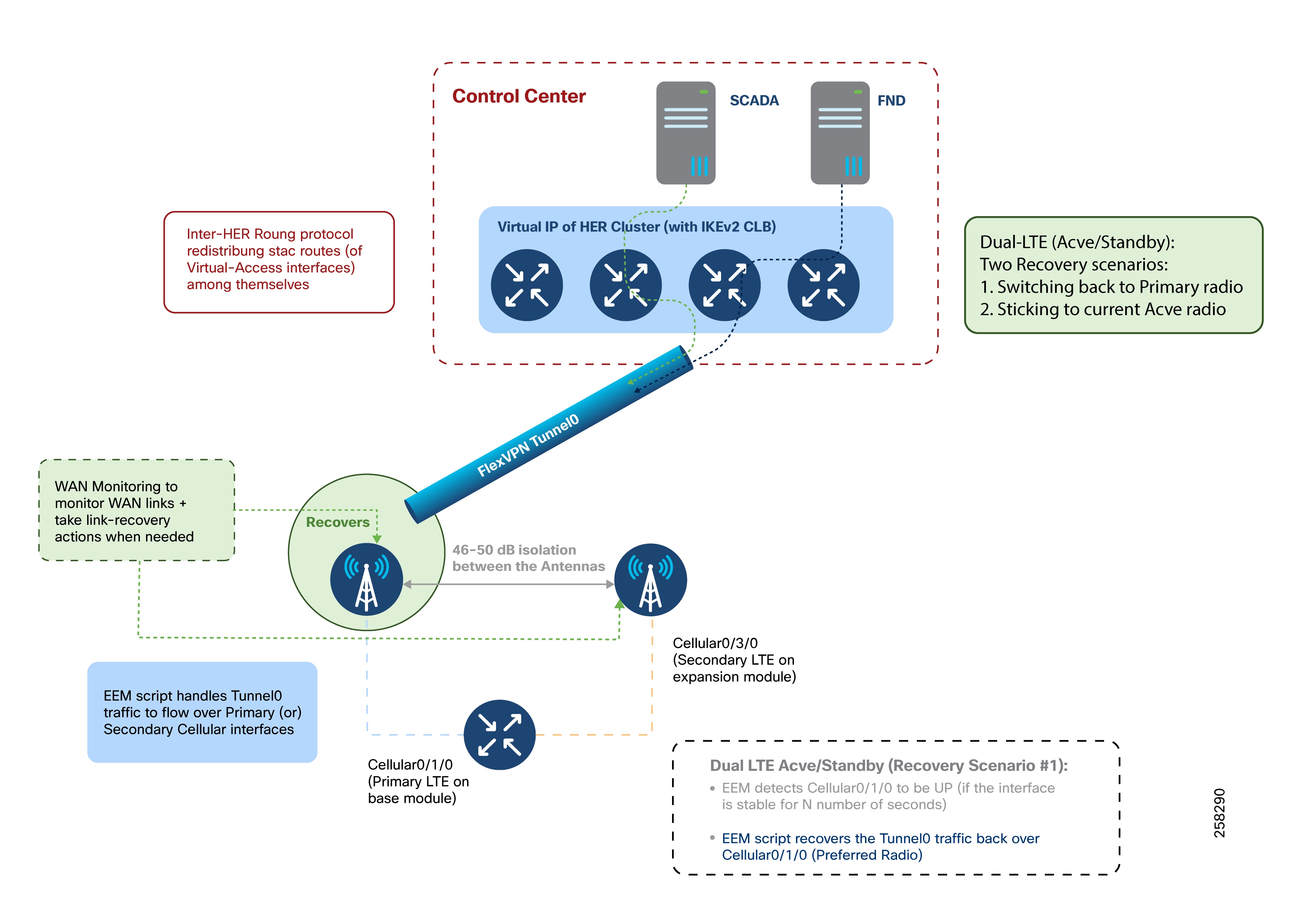
Resiliency Life Cycle
1. Initially, tunnel traffic flows over Primary Radio A; Secondary Radio B is up but unused.
2. If Primary Radio A fails, the EEM script detects the failure and reroutes tunnel traffic over Secondary Radio B.
3. The script continues to monitor Radio A.
4. If Radio A recovers, and after a stabilization wait period, tunnel traffic can be switched back to Radio A (Option 1) or remain on Radio B (Option 2).
5. At any point, the non-active radio remains up and ready for failover.
This approach ensures that a single tunnel and a single radio are active at any time, providing seamless failover and rapid recovery.
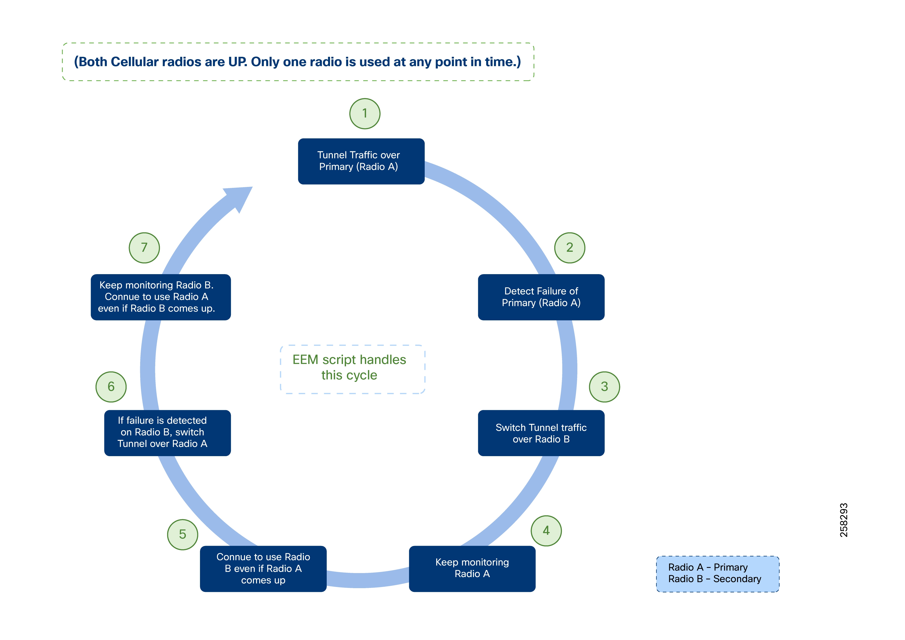
Active/Active Load-Sharing Scenario
In the Active/Active load-sharing scenario, both LTE interfaces are active, each establishing a separate FlexVPN tunnel (Tunnel0 over the primary LTE, Tunnel1 over the secondary LTE).
● Each tunnel terminates on a different HER at the control center.
● Sufficient antenna isolation must be maintained, and WAN monitoring is deployed to track link status.
● Both tunnels are operational and share traffic load (per-destination load balancing).
● If one LTE interface fails, only the corresponding tunnel is lost; traffic continues uninterrupted over the remaining tunnel.
● Inter-HER routing protocols must be enabled to advertise the virtual-access interfaces for each HER.
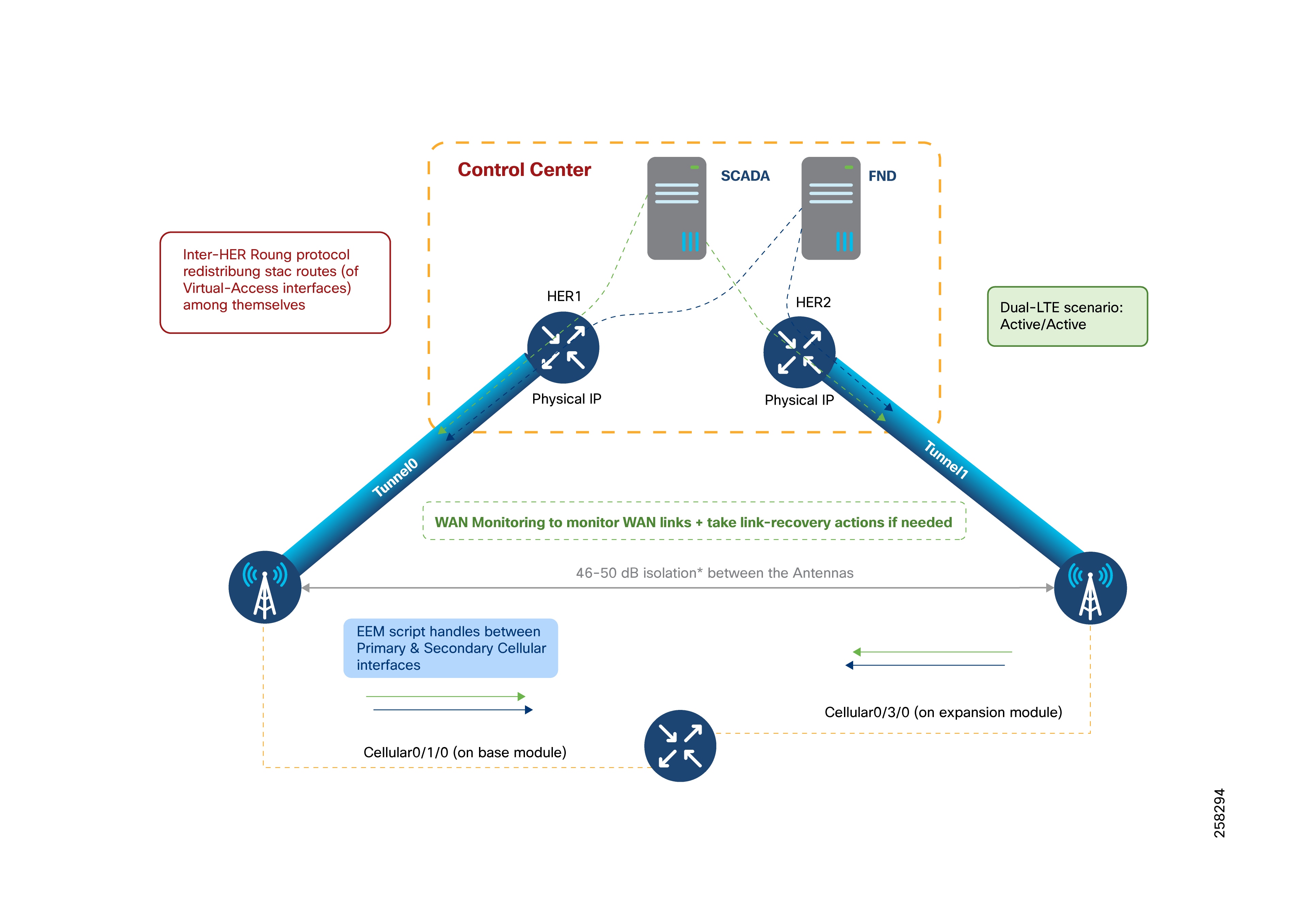
Resiliency Life Cycle
● Tunnel0 uses Primary Radio A; Tunnel1 uses Secondary Radio B.
● Traffic is load-balanced across both tunnels.
● If either radio fails, EEM script detects the failure, and traffic is consolidated to the remaining active tunnel.
● Critical traffic is prioritized via QoS policies.
● When the failed radio recovers, tunnel connectivity is restored, and load balancing resumes.
● The cycle repeats as needed, ensuring continuous service.
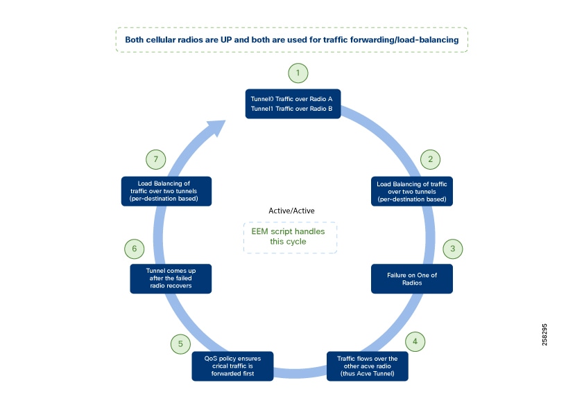
Design Considerations
Cellular failures (cellular gateway interface or provider-side) are handled by HER using Dead Peer Detection (DPD), expiring the virtual-access interface on the HER after a configured interval.
Design considerations include:
1. Critical communication like IEC 61850 layer2 GOOSE messages could continue to flow uninterrupted using the second tunnel/radio.
2. Northbound unsolicited report/communication (Layer 3) from the DA cellular gateway to the SCADA control center could continue to flow uninterrupted using the second tunnel/radio.
3. Southbound solicited poll/command (Layer 3) from the SCADA control center to the DA Cellular gateway could be classified into two sub-categories:
a. If return traffic hits the HER where the FlexVPN tunnel was terminated before the cellular failure (ex-HER).
b. If return traffic hits any other HER (apart from Ex-HER).
4. Southbound solicited polls/commands hitting Ex-HER in the return path require an DPD expiry period to resume Active traffic. This is because the Virtual-Access interface on HER (corresponding to the FlexVPN Tunnel, that went down on cellular gateway) needs to be brought down after the DPD expiry period. It is recommended to have SCADA retry interval of 3 as a mitigation step.
5. Southbound solicited polls/command hitting any other HER could continue to flow uninterrupted using the secondary tunnel over the secondary radio.
Table 26. Pros and cons of Dual-LTE Scenarios
| Dual-LTE Scenario |
Pros |
Cons |
| Active/Standby-SHUT |
● Standby interface is kept in shutdown state.
● No cellular cost on standby radio, as long as long as Active radio is used.
● Cellular cost on only one radio at any given time.
|
Relatively high failover timers because:
●
Cellular interface has to be brought up from shutdown state.
●
Once it is up, the FlexVPN Tunnel has to be re-established over secondary radio.
|
| Active/Standby-UP |
●
Standby interface is kept in UP state (but unused).
●
No cellular cost on standby radio, as long as long as Active radio is used.
●
Cellular cost on only one radio at any given time.
|
Relatively fewer failover timers because:
●
As the secondary cellular interface is already UP, the FlexVPN tunnel could be readily re-established over it.
|
| Active/Active |
●
Load sharing the traffic over two different Active radios with the same control center.
●
In case of failure of one radio, switchover to serve traffic northbound to control center should be almost immediate.
●
When coupled with L2Tpv3 pseudowire resiliency, Active/Active should provide an almost immediate switchover for any Layer2 communication (for example, IEC 61850 GOOSE communication).
|
Active/Active scenario would result in 2X Tunnel scale design at the HER Cluster. |
EEM Script and WAN Monitoring
● EEM scripts can track the line-protocol status for quick failover or recovery or use IP SLA for broader reachability monitoring.
● A stabilization period (for example, 120 seconds) is recommended before declaring an interface fully recovered.
● WANMon provides local monitoring and automated link recovery, with configurable recovery levels (e.g., interface reset, module reload, system reload).
The following scalability parameters apply to the Distribution Automation HER architecture.
● A cluster of six to seven Cisco C8500-12X routers can aggregate up to 50,000 tunnels (i.e., 50,000 DA Gateways).
● Two such clusters can support up to 100,000 tunnels or DA Gateways.
● Each C8500-12X router supports up to 120 Gbps Cisco Express Forwarding aggregate throughput.
For more information, visit the Cisco Catalyst 8500 Series Platforms page.
Note: Cisco IoT FND Release 5.0 and later can provision and manage up to 50,000 DA Gateways or SSRs.
The Cisco DA Solution offers a multi-service, secure, and converged architecture for various Distribution Automation (DA) use cases.
● The Cisco DA Gateway or SSR is central to the solution, providing interfaces to connect modern IEDs and legacy RTUs to centralized SCADA systems.
● Secure provisioning of DA Gateways is achieved via ZTD and PnP-based staging.
● DA Gateways can be provisioned for IED-to-SCADA, IED-to-SCADA via RTU, or IED-to-IED (peer-to-peer) IEC 61850 GOOSE multicast communication over emulated Layer 2 using VXLAN and PIM.
● DA Gateways can replicate or route DA application traffic to dual control centers for application-level redundancy.
● Multiple backhaul options (cellular and Ethernet) are supported, with WAN monitoring for redundancy and failover.
● Gateways offer SCADA Gateway service for protocol conversion and raw socket transport of legacy serial traffic.
● Value-added services include encryption, NAT, NTP, DHCP, edge compute, and QoS.
● Headend blocks provide firewall and PKI services; simplified Cisco IoT FND headend with PSK deployment is available for greenfield environments.
● HER routes application traffic to SCADA and offers VRF for application segmentation.
● HER clustering enables scalable aggregation of traffic from DA Gateways and SSRs.
● Cisco IoT FND manages DA Gateways and edge applications.
In summary, the Cisco DA solution enables DSOs to migrate legacy systems and support advanced applications such as Integrated Volt/VAR, fully automated FLISR, Distributed Energy Resources, and microgrids.
![]() Appendix A: Related Documentation
Appendix A: Related Documentation
Cisco IoT Field Network Director
Cisco IoT Field Network Director User Guide, Release 5.0
Cisco FAN - Headend Deep Dive Implementation and FAN Use Cases
Cisco Next-Generation Cryptography
Cisco Guide to Harden Cisco IOS Devices
IR1101 Industrial Integrated Services Router Hardware Installation Guide
Table 27. Acronyms and initialisms used in this guide
| Term |
Definition |
| AD |
Active Directory |
| AMI |
Advanced Meter Infrastructure |
| AMP |
Advanced Malware Protection |
| ASA |
Cisco Adaptive Security Appliances |
| AVC |
Application Visibility Control |
| CA |
Certificate Authority |
| CBC |
Capacitor Bank Controller |
| CGRs |
Cisco Connected Grid Routers |
| CLB |
Cluster Load Balancing |
| CROB |
Control Relay Output Block |
| DA |
Distribution Automation |
| DER |
Distributed Energy Resources |
| DHCP |
Dynamic Host Configuration Protocol |
| DM |
IoT Device Manager |
| DMS |
Distribution Management System |
| DMVPN |
Dynamic Multipoint Virtual Private Network |
| DNS |
Domain Naming Server |
| DPD |
Dead Peer Detection |
| DSO |
Distribution System Operator |
| DTM |
Dynamic Synchronous Transfer Mode |
| DVTI |
Dynamic Virtual Tunnel Interfaces |
| ECC |
Elliptic-curve cryptography |
| FAN |
Field Area Network |
| FCAPS |
Fault, Configuration, Accounting Performance, and Security |
| FLISR |
Fault Location Isolation and Service Restoration |
| FND |
Field Network Director |
| FND-DB |
Field Network Director Database |
| GIS |
Geological Information System |
| GOOSE |
Generic Object Orient State Event |
| GRE |
Generic Routing Encapsulation |
| HMI |
Human Machine Interface |
| HSRP |
Hot Standby Router Protocol |
| IED |
intelligent electronic device |
| IKEV2 |
Internet Key Exchange v2 |
| IPCP |
IP Control Protocol |
| IPS |
Intrusion Prevention System |
| LLG |
Least Loaded Gateway |
| MDM |
Meter Data Management |
| MMS |
Manufacturing Message Specification |
| NAT |
Network Address Translation |
| NHRP |
Next Hop Resolution Protocol |
| NMS |
Network Management System |
| NOC |
Network Operating Center |
| NPS |
Microsoft Network Policy Server |
| NTP |
Network Time Protocol |
| OMS |
Outage Management System |
| PAC |
Protection, Automation and Control |
| PAT |
Port Address Translation |
| PnP |
Plug and Play |
| RA |
Registration Authority |
| RBAC |
Role-Based Access Control |
| RCS |
Remote Control Switch |
| RFI |
Remote Fault Indicator |
| RTU |
Remote Terminal Unit |
| SAIDI |
System Average Interruption Duration Index |
| SAIFI |
System Average Interruption Frequency Index |
| SCADA |
Supervisory Control and Data Acquisition |
| SCEP |
Simple Certificate Enrollment Protocol |
| SOAP |
Simple Object Access Protocol |
| SSR |
Secondary Substation Routers |
| TCO |
Total Cost of Ownership |
| TCP |
Transmission Control Protocol |
| TPS |
Tunnel Provisioning Server |
| UDP |
User Datagram Protocol |
| VRF |
Virtual Routing and Forwarding |
| WAN |
Wide Area Network |
| ZTD |
Zero Touch Deployment |