Design Overview
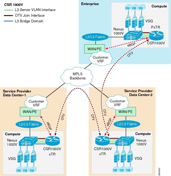
Cisco's Disaster Recovery as a Service (DRaaS) architecture supports virtual data centers that consist of a collection of geographically-dispersed data center locations. Since data centers are distributed geographically, a combination of Layer 2 (L2) and Layer 3 (L3) connectivity is required to support different applications. The L2 Ethernet and L3 IP connectivity between data centers is addressed by a combination of next-generation Cisco Overlay Transport Virtualization (OTV) and Cisco Locator/ID Separation Protocol (LISP) technology, respectively. The DRaaS architecture is built over Virtual Multiservices Data Center (VMDC) 4.0 architecture (Figure 2-1).
Figure 2-1 DRaaS Architecture
CSR Role in DRaaS Architecture
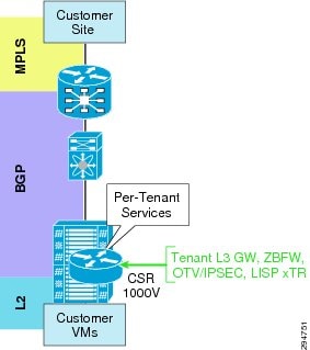
The VMDC VSA 1.0 tenancy model is designed with dedicated CSR1000v per tenant. Apart from being a virtual router, CSR would be used for other functionality within the DRaaS architecture. The roles are defined below as shown in Figure 2-2:
•![]() Aggregation router—L3 gateway for server VLANs
Aggregation router—L3 gateway for server VLANs
•![]() Routing
Routing
•![]() IPSec (AES)—Encryption of tenant traffic over OTV (Data Security)
IPSec (AES)—Encryption of tenant traffic over OTV (Data Security)
•![]() Firewall—Zone-based Firewall policy for server traffic
Firewall—Zone-based Firewall policy for server traffic
•![]() OTV for layer-2 extension
OTV for layer-2 extension
•![]() LISP for VM mobility
LISP for VM mobility
Figure 2-2 CSR Role in DRaaS Architecture
Changes from VSA 1.0
The DRaaS System is built on top of the VSA 1.0 architecture using OTV and LISP technologies. Below are some modifications made to the VSA 1.0 architecture:
1. ![]() Route advertisement for same server VLAN subnet in two tenancy models from two data centers.
Route advertisement for same server VLAN subnet in two tenancy models from two data centers.
2. ![]() OTV configurations on both CSRs in two tenancy models in two data centers. Each tenancy model uses dedicated CSRs for OTV.
OTV configurations on both CSRs in two tenancy models in two data centers. Each tenancy model uses dedicated CSRs for OTV.
3. ![]() Use same server VLANs in two tenant containers to establish L2 connectivity over OTV between the two data centers.
Use same server VLANs in two tenant containers to establish L2 connectivity over OTV between the two data centers.
4. ![]() Use VLAN instead of VXLAN - Dynamic MAC addresses don't get advertised in OTV bridge-domain. See Best Practices and Caveats section for more information.
Use VLAN instead of VXLAN - Dynamic MAC addresses don't get advertised in OTV bridge-domain. See Best Practices and Caveats section for more information.
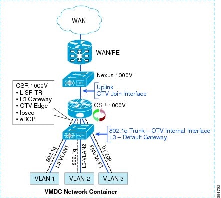
CSR Interface Usage and Functionality
Within the VMDC VSA network containers, CSR 1000V has L3 interfaces for each server VLAN and uplink interfaces peered with the PE device (Figure 2-3). An additional 802.1q L2 trunk interface is configured on the CSR to support DRaaS. The uplink interface will be used as join interface within OTV and the L2 trunk interface will be used as an internal interface with service instances linking to VLAN tags within the bridge group. Zone-based firewall policies will be implemented as per VMDC architecture.
Figure 2-3 VMDC Network Container
Data Center Interconnect Design Considerations
The Cisco Overlay Transport Virtualization (OTV) technology on the Cloud Services Router (CSR1000V) will be utilized in this DRaaS System to provide L2 extension and connectivity between the Enterprise DC and Provider DC (Figure 2-4).
OTV is an IP-based functionality designed to provide L2 extension capabilities over any transport infrastructure: L2-based, L3-based, IP switched, label switched, and so on. The only requirement from the transport infrastructure is providing IP connectivity between remote data center sites. OTV enables L2 connectivity between separate L2 domains while keeping these domains independent and preserving the fault-isolation, resiliency, and load-balancing benefits of an IP-based interconnection. OTV can be thought of as MAC-address routing, in which destinations are MAC addresses, and next hops are IP addresses. OTV simply maps MAC address destinations to IP next hops that are reachable through the network cloud. Traffic destined for a particular MAC address is encapsulated in IP and carried through the IP cloud to its MAC-address routing next hop. OTV encapsulates the MAC frame in an IP/UDP packet.
Typical DCI deployment scenarios like VPLS on ASR9000, or OTV on Nexus7000 or ASR1000, are router-based, multi-tenant, and provider-managed scenarios where the DC WAN edge router (ASR9000, ASR1000) or DC aggregation router/switch (Nexus7000) is utilized for providing DCI and L2 extension for multiple tenants. These deployment scenarios can be point-to-point or multi-point (depending on the DCI technology or platform), and have scale constraints based on the number of sites, VLANs, MACs, bridge-domains, pseudowires, etc.
However, the DRaaS system utilizes a per-tenant CSR1000V for OTV-based DCI and l2 extension. This will be a per-tenant point-to-point DCI scenario and will not have the scale constraints associated with multi-tenant DCI scenarios. OTV is first supported on the CSR1000V in IOS-XE release 3.10.
Figure 2-4 Per-Tenant CSR 1000V as OTV Edge Device
OTV Terminology
Site—A Site is a single or multi-homed connected network that is typically under the control of a single organization. Sites are connected together via edge devices that operate in an overlay network. The edge devices provide L2 connectivity among the sites.
Edge Device (ED)—The edge device connects the site to the (WAN/MAN) core. The edge device is responsible for performing all the OTV functions. A given site can have multiple OTV edge devices.
Internal Interface—The internal or access interfaces are those interfaces on the edge devices that face the site. Internal interfaces behave as regular L2 interfaces. Spanning tree Bridge Protocol Data Units (BPDUs) are received and processed on the internal interfaces as they would be on a regular LAN bridge device.
Join Interface—Join interface is the interface of the edge device that faces the core. Join interface is typically point-to-point routed interface connecting the sites to the core. They are used to join the core multicast groups used by OTV.
Overlay Interface—Overlay interface is a logical multi-access, multicast-capable interface. The overlay interface encapsulates L2 frames in IP unicast or multicast headers. The overlay interface is realized by overlaying one or more physical core-facing interfaces.
OTV Packet Flow
When an ED receives a L2 frame on an internal interface, OTV performs the MAC table lookup based on the destination address of the L2 frame. If the frame is destined to a MAC address that is reachable through another internal interface, the frame is forwarded on that internal interface. OTV performs no other actions and the processing of the frame is complete.
If the frame is destined to a MAC address that was learned over an overlay interface, OTV performs the following tasks:
•![]() Strips the preamble and frame check sequence (FCS) from the L2 frame.
Strips the preamble and frame check sequence (FCS) from the L2 frame.
•![]() Adds an OTV header to the L2 frame and copies the 802.1Q information into the OTV header.
Adds an OTV header to the L2 frame and copies the 802.1Q information into the OTV header.
•![]() Adds the IP address to the packet based on the initial MAC address table lookup. This IP address is used as the destination address for the IP packet that is sent into the core switch.
Adds the IP address to the packet based on the initial MAC address table lookup. This IP address is used as the destination address for the IP packet that is sent into the core switch.
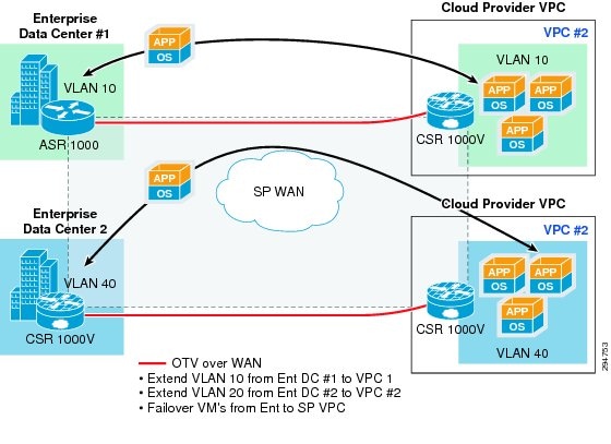
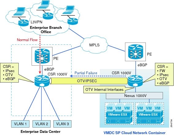
OTV traffic appears as IP traffic to the network core. At the destination site, the ED performs the reverse operation and presents the original L2 frame to the local site. The ED determines the correct internal interface to forward the frame on, based on the local MAC address table. Figure 2-5 shows the use of CSR/OTV to enable partial failovers between the enterprise and service provider (SP) data centers. CSR 1000V within the SP network container will be used as an OTV edge device. The traffic from the enterprise users always flows through the primary Enterprise data center during normal operations and during partial failover scenarios. The network services like firewall and load balancing will also be provided from the Enterprise data center during normal and partial failover scenarios. Only during full failover of the enterprise site in to the SP's VPC, will users be able access the recovery environment directly from the SP cloud and all the related network services will be provided from the SP cloud.
In this scenario, inter-VLAN routing for failed-over VMs in the provider cloud will happen locally in the Provider DC. Load balancing services for the failed-over VMs will be provided by the server load balancing (SLB) in the provider DC. The Zone-Based Firewall (ZBFW) residing on CSR 1000V in the Provider DC will provide FW services for the failed-over VMs. The VSG in the Provider DC will provide compute FW services for the migrated VMs.
In partial failover scenario, since there are dual gateways in each VLAN (Enterprise and SP Data Center), First Hop Redundancy Protocol (FHRP) filtering (HSRP localization) needs to be configured for egress path optimization. The replicated traffic between the enterprise and SP data centers will always flow through the OTV Tunnel. Also, the server-to-server communication in partial failover scenario will flow through the OTV Tunnel. All the east-west traffic flowing through the OTV will be encrypted via IPsec.
Figure 2-5 OTV Deployment to Enable Partial Failovers
Network Encryption
CSR 1000v will provide OTV transport as well as encryption via IPsec for the replicated traffic between the enterprise and SP data centers. The OTV packets will get encrypted and then be transported over the IP WAN. IPsec crypto map will be applied on the overlay interface.
IPsec over OTV provides data security over LAN extension between data centers. CSR1000V supports Advanced Encryption Standard (AES) and Triple Data Encryption Standard (3DES) encryption. 3DES is CPU-intensive and offers lower throughput compared to AES. Apart from IPsec header, packets over OTV have OTV header. This reduces packet MTU. It is important to configure a proper MTU on the overlay interface and IS-IS to prevent packets from getting fragmented. Packet fragmentation lowers the throughput considerably based on the findings; the ideal MTU size is 1372 bytes.
 Feedback