Implementation Overview
This chapter describes the Cisco VMDC 2.1 architecture implementation. The following major sections are discussed:
•![]() Infrastructure Implementation
Infrastructure Implementation
•![]() Additional Technology Implementation
Additional Technology Implementation
•![]() Additional Product Implementation
Additional Product Implementation
As a reference model, Cisco VMDC 2.1 is both flexible and extensible, and may need to be extended or modified to meet the requirements of a specific enterprise data center network.
Functional Components
The Cisco VMDC 2.1 data center network design is based on a proven layered approach, which has been tested and improved over the past several years in some of the largest data center implementations in the world. The layered approach is the basic foundation of the data center design that seeks to improve scalability, performance, flexibility, resiliency, and maintenance.
The four layers covered in this implementation guide are:
•![]() Aggregation Layer
Aggregation Layer
•![]() Services Layer
Services Layer
•![]() Access Layer/Virtual Access Layer
Access Layer/Virtual Access Layer
•![]() Compute Layer
Compute Layer
This guide also includes some sample implementation details for the following additional layers:
•![]() Core Layer
Core Layer
•![]() Management Layer
Management Layer
•![]() Storage Layer
Storage Layer
In addition to the layered datacenter design, the Cisco VMDC 2.1 network implementation is done with the following key operational parameters in mind.
High Availability through:
•![]() Device redundancy
Device redundancy
•![]() Link redundancy
Link redundancy
•![]() Path redundancy
Path redundancy
Performance and Scalability through:
•![]() N×10 Gigabit Ethernet Switching Infrastructure
N×10 Gigabit Ethernet Switching Infrastructure
•![]() vPC (Virtual Port Channels) and MEC (Multi-Chassis EtherChannels)
vPC (Virtual Port Channels) and MEC (Multi-Chassis EtherChannels)
•![]() Fast convergence
Fast convergence
Service Assurance through:
•![]() QoS classification and marking
QoS classification and marking
•![]() Traffic flow matching
Traffic flow matching
•![]() Bandwidth guarantees
Bandwidth guarantees
•![]() Rate limits
Rate limits
Tenant Separation at each network layer:
•![]() Core Layer: Virtual Routing and Forwarding (VRF)
Core Layer: Virtual Routing and Forwarding (VRF)
•![]() Aggregation Layer: VRF, VLAN
Aggregation Layer: VRF, VLAN
•![]() Services Layer: VRF, VLAN, and Virtual Device Contexts
Services Layer: VRF, VLAN, and Virtual Device Contexts
•![]() Access Layer: VLAN
Access Layer: VLAN
•![]() Virtual Access Layer: VLAN
Virtual Access Layer: VLAN
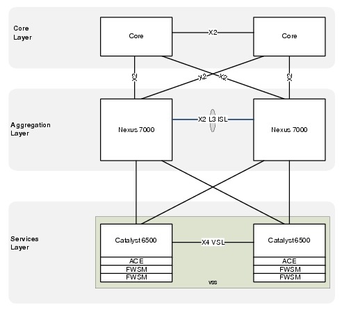
Physical Topology
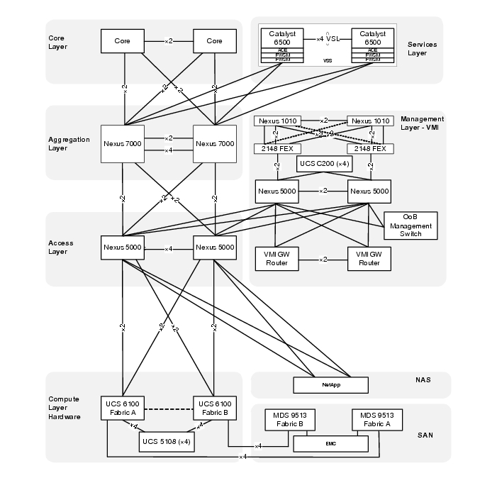
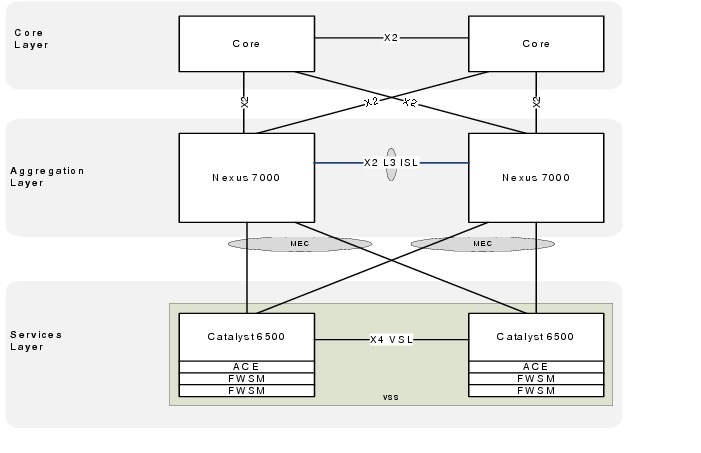
The Cisco VMDC 2.1 network infrastructure deployment models the standard Cisco three-tier hierarchical architecture model (core, aggregation, access). This data center network design is based on a proven layered approach, which has been tested and improved over the past several years in some of the largest data center implementations in the world. The layered approach is the basic foundation of the data center design that seeks to improve scalability, performance, flexibility, resiliency, and maintenance. Figure 2-1 illustrates the overall Cisco VMDC 2.1 physical topology.
Figure 2-1 Cisco VMDC 2.1 Physical Topology
Logical Topology
Logical topologies are bound to network protocols and describe how data is moved across the network. The Cisco VMDC 2.1 basic tenant concept is modeled after a simple datacenter structure containing a public/common server farm and a secure/private server farm.
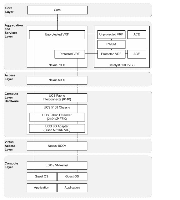
Figure 2-2 represents the Cisco VMDC 2.1 logical tenant topology that is created on the physical topology in Figure 2-1.
Figure 2-2 Cisco VMDC 2.1 Logical Topology
Tenant Model
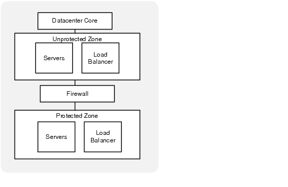
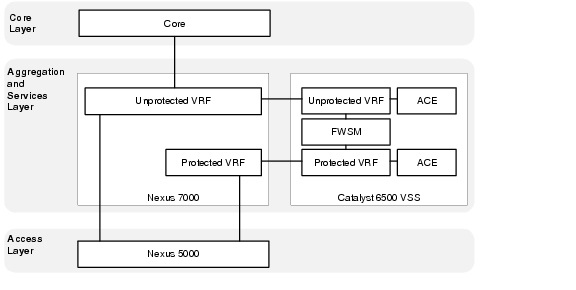
The Cisco VMDC 2.1 tenant concept is modeled on a basic aggregation block containing both a common server farm and a secure server. Each tenant has an unprotected (public/common) zone and a protected (private/secure) zone.
Figure 2-3 depicts a logical view of a single tenant.
Figure 2-3 Single Tenant Logical Diagram
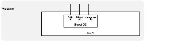
Each Server Virtual Machine (VM) deployed within a tenant protected or unprotected zone is assumed to have three network interfaces (NICs).
•![]() Front End - These interfaces are used for external access (HTTP, HTTPS, etc.) to the server or cluster, which can be accessed by application servers or users that are submitting jobs or retrieving job results from the cluster.
Front End - These interfaces are used for external access (HTTP, HTTPS, etc.) to the server or cluster, which can be accessed by application servers or users that are submitting jobs or retrieving job results from the cluster.
•![]() Back End - These interfaces provide inter-compute node communications (clustering) and potentially a back-end high-speed storage path (NFS). Typical requirements include low latency and high bandwidth and may also include jumbo frame support.
Back End - These interfaces provide inter-compute node communications (clustering) and potentially a back-end high-speed storage path (NFS). Typical requirements include low latency and high bandwidth and may also include jumbo frame support.
•![]() Management - This interface provides out-of-band (OoB) management for the cloud administrative tools or remote access for server administration.
Management - This interface provides out-of-band (OoB) management for the cloud administrative tools or remote access for server administration.
Figure 2-4 Virtual interfaces per VM
VLAN Allocation
In Cisco VMDC 2.1, the tenant VLAN scheme is flexible for different tenants or different tenant zones. The goal of the design was to allocate VLANs for different purposes spanning different devices or layers in the architecture. The Cisco VMDC 2.1 model tenant VLAN allocation was done as follows:
•![]() 3 front-end (Public) VLANs
3 front-end (Public) VLANs
•![]() 1 or 2 backend (Private) VLANs
1 or 2 backend (Private) VLANs
•![]() 1 VM management VLAN
1 VM management VLAN

Note ![]() Throughout this document, example configurations reference the VLANs in Table 2-1.
Throughout this document, example configurations reference the VLANs in Table 2-1.
IP Addressing
In Cisco VMDC 2.1, the tenant IP addressing scheme is flexible and can support public or private addressing. The VRF segmentation would also allow overlapping IP spaces for different tenants give the assumption that complete path isolation is provided end to end. Table 2-2 is an example of tenant IP address modeling done in a private address block. If a tenant is assigned a contiguous block of subnets within the datacenter, the routing may be summarized when it is advertised to the rest of the network. In addition, only a small number of static routes are needed to provide reachability between a tenant's unprotected and protected zones.
Note ![]() Throughout this document, example configurations reference the addresses in Table 2-2.
Throughout this document, example configurations reference the addresses in Table 2-2.
Virtual Routing and Forwarding (VRF)
In Cisco VMDC 2.1, Layer 3 separation between tenants and between tenant zones is accomplished using Virtual Routing and Forwarding (VRF). VRF instances allow multiple routing configurations in a single Layer 3 switch using separate virtual routing tables. By default, communication between VRF instances is not allowed to protect the privacy of each tenant zone.
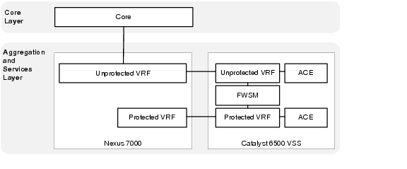
Each tenant is assigned two VRF instances, one that forms the unprotected (public) zone and another that creates protected (private) zone. Routing information is carried across all the hops in each tenant's Layer 3 domain, and each tenant's unprotected and protected VRF is mapped to one or more VLANs in a Layer 2 domain.
Figure 2-5 depicts a completed logical topology showing the unprotected and protected VRFs extending into the services layer and the server VLANs as they extend to the access layer and then continue throughout the rest of the Layer 2 domain.
Figure 2-5 Cisco VMDC 2.1 Logical Topology
Routing
In Cisco VMDC 2.1, dynamic routing for each tenant is accomplished using OSPF as the interior gateway protocol. The remainder of the routing information is provided via static routes which are redistributed into OSPF at the Autonomous System Border Router (ASBR).
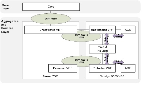
Not-so-stubby areas (NSSAs) are an extension of OSPF stub areas. Stub areas prevent the flooding of external link-state advertisements (LSAs) into NSSAs, relying instead on default routes to external destinations. NSSAs are more flexible than stub areas in that a NSSA can import external routes into the OSPF routing domain.
If the FWSM context is deployed in routed mode (recommended as the most flexible option) the unprotected becomes a true NSSA with the connection to Area 0 and the protected OSPF area is almost effectively a totally NSSA area given there is no connection to area 0 and a default static route is used to exit to the unprotected zone. In Figure 2-6, two separate routing domains are connected via static routes on the FWSM.
Figure 2-6 Tenant Routing with FWSM in Routed Mode
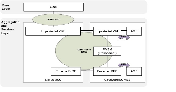
If the FWSM context is deployed in transparent mode, the unprotected and protected interfaces form an OSPF adjacency. The OSPF NSSA is extended through the FWSM, which forms a single routing domain. In this case, all routing information will be populated in both tenant zones.
Figure 2-7 Tenant Routing with FWSM in Transparent Mode
Management Implementation
The Cisco VMDC 2.1 solution does not focus on a specific management network architecture. The Virtual Management Infrastructure (VMI) described in this section illustrates an example deployment of a management network and how it integrates into the overall VMDC architecture.
Virtual Management Infrastructure (VMI)
Virtual Management Infrastructure (VMI) is a network that hosts additional infrastructure that employs a variety of tools, applications, and additional devices to assist human network managers in monitoring and maintaining the overall Cisco VMDC 2.1 architecture.
The software applications may include, but are not limited to, the following list:
•![]() Unified Computing System Manager (UCSM)
Unified Computing System Manager (UCSM)
•![]() Cisco Fabric Manager (FM)
Cisco Fabric Manager (FM)
•![]() VMware vSphere
VMware vSphere
•![]() BMC orchestration tools
BMC orchestration tools
Additional hardware, such as the Nexus 1010 and Network Analysis Modules (NAM), would be deployed in VMI.
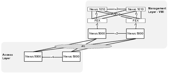
Physical Topology
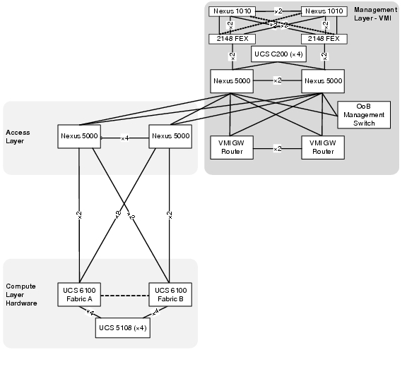
All VMDC infrastructure devices use the local management VRF and mgmt 0 interface to provide Out-of-Band (OoB) management connection to the VMI OoB management switch.
VMI uses a separate distribution layer (gateway routers) to provide routing functionality between VMI VLANs and connectivity to any internal or external networks.
VMI also employs an additional pair of Nexus 5000 switches to serve as a dedicated access layer for the compute resources contained within VMI. The VMI access switches are directly connected to the Cisco VMDC 2.1 infrastructure via the VMDC Nexus 5000 access switches.
The required management VLANs are extended from VMI through the access layer and into the virtual access and compute layers providing Layer 2 adjacent connectivity to all ESXi hosts as well as all server virtual machines residing on UCS.
Figure 2-8 Cisco VMI Physical Topology
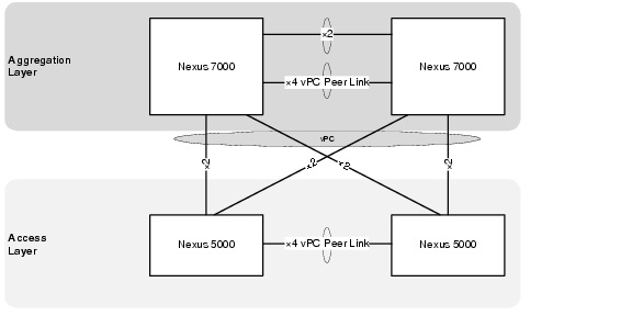
vPC Implementation
A virtual port channel (vPC) allows links that are physically connected to two different Cisco Nexus 5000 Series devices to appear as a single port channel by a third device. The third device can be a switch, server, or any other networking device that supports port channels. A vPC provides Layer 2 multipathing, which allows you to create redundancy and increase bisectional bandwidth by enabling multiple parallel paths between nodes and allowing load balancing traffic.
Virtual PortChannels (vPCs) are configured at both the VMI aggregation and VMDC access layers to enable full, cross-sectional bandwidth utilization (40 Gbps) as depicted in Figure 2-9.
Figure 2-9 vPCs connecting VMDC to VMI
The vPC domain includes both vPC peer devices, the vPC peer keepalive link, the vPC peer link, and all the PortChannels in the vPC domain connected to the downstream device.
Example 2-1 VMI vPC Configurations on VMI Nexus 5000 A
vlan 14
name 10.0.14.0_VMI-VM
vlan 32
name VMDC_Device_Mgmt
vlan 33
name EAST-FWSM-Contexts
vlan 34
name EAST-ACE-Contexts
vlan 40
name 10.0.40.0_EAST-ACE1
vlan 41
name 10.0.41.0_EAST-ACE2
vlan 42
name 10.0.42.0_EAST-FWSM1_and_2
vlan 43
name 10.0.43.0_EAST-FWSM3_and_4
vlan 193
name EAST-N1KV-CTRL/PKT
vlan 300
name EAST-NEXUS-1010-CTRL/PKT
!
spanning-tree pathcost method long
spanning-tree vlan 14,32-38,40-47,193,300 priority 24576
!
vpc domain 1
role priority 1
peer-keepalive destination 10.0.14.5
!
interface port-channel1
description vPC PEER-LINK
switchport mode trunk
vpc peer-link
switchport trunk allowed vlan 14,32-38,40-47,193,300
spanning-tree port type network
speed 10000
!
interface port-channel20
description vPC TO EAST VMDC N5Ks
switchport mode trunk
vpc 20
switchport trunk allowed vlan 14,32-38,40-47,193
!
interface Ethernet1/9
switchport mode trunk
switchport trunk allowed vlan 14,32-38,40-47,193
channel-group 20 mode active
!
interface Ethernet1/10
switchport mode trunk
switchport trunk allowed vlan 14,32-38,40-47,193
channel-group 20 mode active
Example 2-2 VMI vPC Configurations on VMI Nexus 5000 A
vlan 14
name 10.0.14.0_VMI-VM
vlan 32
name VMDC_Device_Mgmt
vlan 33
name EAST-FWSM-Contexts
vlan 34
name EAST-ACE-Contexts
vlan 40
name 10.0.40.0_EAST-ACE1
vlan 41
name 10.0.41.0_EAST-ACE2
vlan 42
name 10.0.42.0_EAST-FWSM1_and_2
vlan 43
name 10.0.43.0_EAST-FWSM3_and_4
vlan 193
name EAST-N1KV-CTRL/PKT
vlan 300
name EAST-NEXUS-1010-CTRL/PKT
!
spanning-tree pathcost method long
spanning-tree vlan 14,32-38,40-47,193,300 priority 28672
!
vpc domain 1
role priority 2
peer-keepalive destination 10.0.14.4
!
interface port-channel1
description vPC PEER-LINK
switchport mode trunk
vpc peer-link
switchport trunk allowed vlan 14,32-38,40-47,193,300
spanning-tree port type network
speed 10000
!
interface port-channel20
description vPC TO EAST VMDC N5Ks
switchport mode trunk
vpc 20
switchport trunk allowed vlan 14,32-38,40-47,193
!
interface Ethernet1/9
switchport mode trunk
switchport trunk allowed vlan 14,32-38,40-47,193
channel-group 20 mode active
!
interface Ethernet1/10
switchport mode trunk
switchport trunk allowed vlan 14,32-38,40-47,193
channel-group 20 mode active
VLAN Allocation
In Cisco VMDC 2.1, the management VLAN allocation used is as follows:
Note ![]() Throughout this document, example management configurations reference the VLANs in Table 2-3.
Throughout this document, example management configurations reference the VLANs in Table 2-3.
IP Addressing
In Cisco VMDC 2.1, the management IP allocation uses is as follows:
Note ![]() Throughout this document, example management reference the addresses in Table 2-4.
Throughout this document, example management reference the addresses in Table 2-4.
VMI Software
VMware vSphere
VMware vSphere is the virtualization hypervisor platform best integrated with the current Cisco Unified Computing System. The following vSphere components were used in VMI:
•![]() ESXi 4.1
ESXi 4.1
•![]() vCenter 4,1
vCenter 4,1
•![]() vSphere Update Manager
vSphere Update Manager
•![]() vSphere Management Agent 4.1
vSphere Management Agent 4.1
http://www.vmware.com/files/pdf/products/vsphere/VMware-vSphere-Standard-DataSheet-DS-EN.pdf
Unified Computing System Manager
Unify and Embed Management for Computing
http://www.cisco.com/en/US/products/ps10281/index.html
Fabric Manager Server Package
Infrastructure Implementation
The Cisco VMDC 2.1 network infrastructure deployment models the standard Cisco three-tier hierarchical architecture model (core, aggregation, access) as described in the Datacenter 2.5 and 3.0 infrastructure design guides:
http://www.cisco.com/en/US/docs/solutions/Enterprise/Data_Center/DC_Infra2_5/DCI_SRND_2_5_book.html
http://www.cisco.com/en/US/docs/solutions/Enterprise/Data_Center/DC_3_0/DC-3_0_IPInfra.html
Figure 2-10 shows the basic layered design.design in which the rest of Cisco VMDC 2.1 architecture is built on.
Figure 2-10 Basic Three-Tier Data Center Design
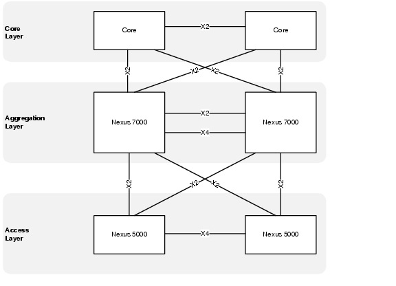
Core Layer
From an overall architecture perspective, provisioning a dedicated pair of data center core switches insulates the core from the remainder of the data center network to improve routing stability and provide a future scale point for the data center topology. If requirements dictate a scenario that needs two or more aggregation blocks, a dedicated data center core network provides ease of deployment for scale expansion with no additional equipment in the data center network.
The Cisco VMDC 2.1 solution does not focus on the core layer; however, some relevant configuration pieces are included in this guide as reference.
Aggregation Layer (Nexus 7000)
The Cisco VMDC 2.1 aggregation layer is deployed using the Cisco Nexus 7000 next generation datacenter switching platform.
The aggregation layer provides a consolidation point where access layer switches are connected as well as delivers connectivity to the core and services layers of the data center. The aggregation layer provides the boundary between Layer 3 routed links and Layer 2 Ethernet broadcast domains as shown in Figure 2-11.
Figure 2-11 Aggregation Layer - Layer 3 and Layer 2 Boundaries
Nexus 7010 Module Details
The Cisco VMDC 2.1 solution was validated using the following Nexus 7010-compatible modules:
Example 2-3 Show Output for Nexus 7010 A Modules
DIST-N7010-A-EAST-DIST-A# show module
Mod Ports Module-Type Model Status
--- ----- ----------------------------------- ------------------ ----------
3 8 10 Gbps Ethernet XL Module N7K-M108X2-12L ok
4 8 10 Gbps Ethernet XL Module N7K-M108X2-12L ok
5 0 Supervisor module-1X N7K-SUP1 active *
6 0 Supervisor module-1X N7K-SUP1 ha-standby
Mod Sw Hw
--- -------------- ------
3 5.1(3) 1.1
4 5.1(3) 1.1
5 5.1(3) 1.1
6 5.1(3) 1.0
Mod MAC-Address(es) Serial-Num
--- -------------------------------------- ----------
3 00-26-51-c6-58-b4 to 00-26-51-c6-58-c0 JAF1339BDRJ
4 00-26-51-c6-7a-ec to 00-26-51-c6-7a-f8 JAF1339BDRR
5 00-22-55-77-ed-88 to 00-22-55-77-ed-90 JAB123400JY
6 00-26-51-c6-7a-58 to 00-26-51-c6-7a-60 JAF1342ARLB
Mod Online Diag Status
--- ------------------
3 Pass
4 Pass
5 Pass
6 Pass
Xbar Ports Module-Type Model Status
--- ----- ----------------------------------- ------------------ ----------
1 0 Fabric Module 1 N7K-C7010-FAB-1 ok
2 0 Fabric Module 1 N7K-C7010-FAB-1 ok
3 0 Fabric Module 1 N7K-C7010-FAB-1 ok
Xbar Sw Hw
--- -------------- ------
1 NA 1.0
2 NA 1.0
3 NA 1.0
Xbar MAC-Address(es) Serial-Num
--- -------------------------------------- ----------
1 NA JAB123400TK
2 NA JAB123400TJ
3 NA JAB1234002M
* this terminal session
Example 2-4 Show Output for Nexus 7010 B Modules
DIST-N7010-B-EAST-DIST-B# show module
Mod Ports Module-Type Model Status
--- ----- -------------------------------- ------------------ ------------
3 8 10 Gbps Ethernet XL Module N7K-M108X2-12L ok
4 8 10 Gbps Ethernet XL Module N7K-M108X2-12L ok
5 0 Supervisor module-1X N7K-SUP1 active *
6 0 Supervisor module-1X N7K-SUP1 ha-standby
Mod Sw Hw
--- -------------- ------
3 5.1(3) 1.1
4 5.1(3) 1.1
5 5.1(3) 1.1
6 5.1(3) 1.0
Mod MAC-Address(es) Serial-Num
--- -------------------------------------- ----------
3 c4-71-fe-d2-cf-2c to c4-71-fe-d2-cf-38 JAF1446BQNK
4 c4-71-fe-1b-d1-70 to c4-71-fe-1b-d1-7c JAF1444CHBE
5 00-22-55-77-ed-30 to 00-22-55-77-ed-38 JAB123400L8
6 00-22-55-77-71-f0 to 00-22-55-77-71-f8 JAB122501A6
Mod Online Diag Status
--- ------------------
3 Pass
4 Pass
5 Pass
6 Pass
Xbar Ports Module-Type Model Status
--- ----- -------------------------------- ------------------ ------------
1 0 Fabric Module 1 N7K-C7010-FAB-1 ok
2 0 Fabric Module 1 N7K-C7010-FAB-1 ok
3 0 Fabric Module 1 N7K-C7010-FAB-1 ok
Xbar Sw Hw
--- -------------- ------
1 NA 1.0
2 NA 1.0
3 NA 1.0
Xbar MAC-Address(es) Serial-Num
--- -------------------------------------- ----------
1 NA JAB121602E1
2 NA JAB1234002H
3 NA JAB123400T8
* this terminal session
VDC Implementation
In the Nexus 7000 switches, the default VDC has unique abilities, including the ability to create up to three additional VDCs per switch (for a total of four VDCs including the default).
In Cisco VMDC 2.1, the default VDC is reserved for administrative functions and a single non-default VDC for production network connections. The VDC configurations appear in Example 2-5 and Example 2-6.
This approach improves flexibility and security. You may grant Administrative access into the non-default VDCs to perform configuration functions without exposing access to reload the switch or change software versions. There are no Layer 3 interfaces in the default VDC that are exposed to the production data network, and only the management interface is accessible through an out-of-band (OOB) management path. In this implementation, the default VDC is maintained as an administrative context that requires console access and/or separate security credentials.
Example 2-5 VDC Definition on the Nexus 7010 A Aggregation Switch Configuration
hostname DIST-N7010-A
!
! default VDC
!
vdc DIST-N7010-A id 1
limit-resource vlan minimum 16 maximum 4094
limit-resource monitor-session minimum 0 maximum 2
limit-resource monitor-session-erspan-dst minimum 0 maximum 23
limit-resource vrf minimum 2 maximum 1000
limit-resource port-channel minimum 0 maximum 768
limit-resource u4route-mem minimum 96 maximum 96
limit-resource u6route-mem minimum 24 maximum 24
limit-resource m4route-mem minimum 58 maximum 58
limit-resource m6route-mem minimum 8 maximum 8
!
! create production VDC
!
vdc EAST-DIST-A id 2
allocate interface Ethernet3/1-8
allocate interface Ethernet4/1-8
boot-order 1
limit-resource vlan minimum 16 maximum 4094
limit-resource monitor-session minimum 0 maximum 2
limit-resource monitor-session-erspan-dst minimum 0 maximum 23
limit-resource vrf minimum 2 maximum 1000
limit-resource port-channel minimum 0 maximum 768
limit-resource u4route-mem minimum 8 maximum 8
limit-resource u6route-mem minimum 4 maximum 4
limit-resource m4route-mem minimum 8 maximum 8
limit-resource m6route-mem minimum 3 maximum 3
Example 2-6 VDC Definition on the Nexus 7010 B Aggregation Switch Configuration
hostname DIST-N7010-B
!
! default VDC
!
vdc DIST-N7010-B id 1
limit-resource vlan minimum 16 maximum 4094
limit-resource monitor-session minimum 0 maximum 2
limit-resource monitor-session-erspan-dst minimum 0 maximum 23
limit-resource vrf minimum 2 maximum 1000
limit-resource port-channel minimum 0 maximum 768
limit-resource u4route-mem minimum 96 maximum 96
limit-resource u6route-mem minimum 24 maximum 24
limit-resource m4route-mem minimum 58 maximum 58
limit-resource m6route-mem minimum 8 maximum 8
!
! create production VDC
!
vdc EAST-DIST-B id 2
allocate interface Ethernet3/1-8
allocate interface Ethernet4/1-8
boot-order 1
limit-resource vlan minimum 16 maximum 4094
limit-resource monitor-session minimum 0 maximum 2
limit-resource monitor-session-erspan-dst minimum 0 maximum 23
limit-resource vrf minimum 2 maximum 1000
limit-resource port-channel minimum 0 maximum 768
limit-resource u4route-mem minimum 8 maximum 8
limit-resource u6route-mem minimum 4 maximum 4
limit-resource m4route-mem minimum 8 maximum 8
limit-resource m6route-mem minimum 3 maximum 3
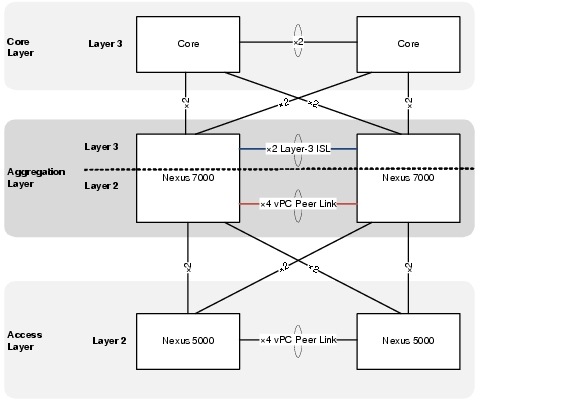
Dual Inter Switch Link Implementation
In Cisco VMDC 2.1, a dual inter switch link (ISL) design is used between the aggregation switches. The Layer 3 inter-switch link is composed of a dedicated 2 x 10Gb port channel that provides OSPF area contiguity and a separate 4 x 10 Gb dedicated port channel that creates the vPC peer link for Layer 2 connectivity to the access layer.
The physical connections are shown in Figure 2-12 and the switch output in Example 2-7.
Figure 2-12 Dual Inter Switch Link Design in Cisco VMDC 2.1
Example 2-7 Aggregation Dual Inter Switch Links (Nexus 7000 A)
! aggregation A side
DIST-N7010-A-EAST-DIST-A# show port-channel summary
Flags: D - Down P - Up in port-channel (members)
I - Individual H - Hot-standby (LACP only)
s - Suspended r - Module-removed
S - Switched R - Routed
U - Up (port-channel)
M - Not in use. Min-links not met
--------------------------------------------------------------------------------
Group Port- Type Protocol Member Ports
Channel
--------------------------------------------------------------------------------
1 Po1(RU) Eth LACP Eth3/3(P) Eth4/3(P)
2 Po2(SU) Eth LACP Eth3/7(P) Eth3/8(P) Eth4/7(P)
Eth4/8(P)
! aggregation B side
DIST-N7010-B-EAST-DIST-B# show port-channel summary
Flags: D - Down P - Up in port-channel (members)
I - Individual H - Hot-standby (LACP only)
s - Suspended r - Module-removed
S - Switched R - Routed
U - Up (port-channel)
M - Not in use. Min-links not met
--------------------------------------------------------------------------------
Group Port- Type Protocol Member Ports
Channel
--------------------------------------------------------------------------------
1 Po1(RU) Eth LACP Eth3/3(P) Eth4/3(P)
2 Po2(SU) Eth LACP Eth3/7(P) Eth3/8(P) Eth4/7(P)
Eth4/8(P)
The Layer 2 vPC implementation is covered in the next section and the Layer 3 implementation is covered in Virtual Routing and Forwarding (VRF).
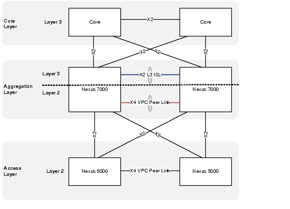
Virtual PortChannel Implementation (vPC)
A virtual port channel (vPC) allows links that are physically connected to two different Cisco Nexus 7000 Series devices to appear as a single port channel by a third device. The third device can be a switch, server, or any other networking device that supports port channels. A vPC provides Layer 2 multipathing, which allows you to create redundancy and increase bisectional bandwidth by enabling multiple parallel paths between nodes and allowing load balancing traffic.
The vPC domain includes vPC peer devices, the vPC peer keepalive link, the vPC peer link, and all the PortChannels in the vPC domain connected to the downstream device
In Cisco VMDC 2.1, virtual PortChannels (vPCs) were configured in the aggregation and access layers enabling full, cross-sectional bandwidth utilization (80 Gbps) as depicted in Figure 2-13.
Figure 2-13 vPCs at the Access and Aggregation Layers
Cisco VMDC 2.1 also leverages two new vPC features added to NX-OS that improve scale and performance during convergence events. These features are peer switch and address resolution protocol (ARP) synchronization.
The vPC peer switch feature addresses the performance of spanning tree protocol (STP) convergence. It allows a pair of Cisco Nexus 7000 Series devices to appear as a single STP root in the Layer 2 topology. This feature eliminates the need to pin the STP root to the vPC primary switch and improves vPC convergence during vPC primary switch failures. To avoid loops, the vPC peer link is excluded from the STP computation. In vPC peer switch mode, STP BPDUs are sent from both vPC peer devices to avoid issues related to STP BPDU timeout on the downstream switches, which can cause traffic disruption.
The ARP synchronization feature addresses table synchronization across vPC peers using the reliable transport mechanism of the Cisco Fabric Service over Ethernet (CFSoE) protocol. You must enable the IP ARP synchronize to support faster convergence of address tables between the vPC peers. This convergence is designed to overcome the delay involved in ARP table restoration for IPv4 table restoration when the peer-link port channel flaps or when a vPC peer comes back online.
The current best practice is to use as much information as possible for input to the EtherChannel algorithm to achieve the best or most uniform utilization of EtherChannel members.
The Cisco VMDC 2.1 vPC validated configuration is in Example 2-8 and Example 2-9:
Example 2-8 Example vPC Configurations on Nexus 7010 Switches (7010 A Configuration)
! set load share algorithm in the default VDC
!
port-channel load-balance ethernet source-dest-ip-port-vlan
!
! STP specific configuration
!
spanning-tree pathcost method long
spanning-tree vlan 201-930 priority 8192
!
! configure vPC in the production VDC
!
vpc domain 201
peer-switch
role priority 16000
peer-keepalive destination 10.0.32.103 source 10.0.32.101
delay restore 60
peer-gateway
reload restore
ip arp synchronize
!
interface port-channel2
description vPC peerlink to EAST-DIST-B
switchport
switchport mode trunk
switchport trunk allowed vlan 201-930
spanning-tree port type network
service-policy type queuing output 10G-EGRESS-Q
vpc peer-link
!
interface Ethernet3/7
description To DIST-N7010-B-EAST-DIST-B Eth3/7
switchport
switchport mode trunk
switchport trunk allowed vlan 201-930
channel-group 2 mode active
no shutdown
!
interface Ethernet3/8
description To DIST-N7010-B-EAST-DIST-B Eth3/8
switchport
switchport mode trunk
switchport trunk allowed vlan 201-930
channel-group 2 mode active
no shutdown
!
interface Ethernet4/7
description To DIST-N7010-B-EAST-DIST-B Eth4/7
switchport
switchport mode trunk
switchport trunk allowed vlan 201-930
channel-group 2 mode active
no shutdown
!
interface Ethernet4/8
description To DIST-N7010-B-EAST-DIST-B Eth4/8
switchport
switchport mode trunk
switchport trunk allowed vlan 201-930
channel-group 2 mode active
no shutdown
Example 2-9 Example vPC Configurations on Nexus 7010 Switches (7010 B Configuration)
! set load share algorithm in the default VDC
!
port-channel load-balance ethernet source-dest-ip-port-vlan
!
! STP specific configuration
!
spanning-tree pathcost method long
spanning-tree vlan 201-930 priority 8192
!
! configure vPC in the production VDC
!
vpc domain 201
peer-switch
role priority 32000
peer-keepalive destination 10.0.32.101 source 10.0.32.103
delay restore 60
peer-gateway
reload restore
ip arp synchronize
!
interface port-channel2
description vPC peerlink to EAST-DIST-A
switchport
switchport mode trunk
switchport trunk allowed vlan 201-930
spanning-tree port type network
service-policy type queuing output 10G-EGRESS-Q
vpc peer-link
!
interface Ethernet3/7
description To DIST-N7010-A-EAST-DIST-A Eth3/7
switchport
switchport mode trunk
switchport trunk allowed vlan 201-930
channel-group 2 mode active
no shutdown
!
interface Ethernet3/8
description To DIST-N7010-A-EAST-DIST-A Eth3/8
switchport
switchport mode trunk
switchport trunk allowed vlan 201-930
channel-group 2 mode active
no shutdown
!
interface Ethernet4/7
description To DIST-N7010-A-EAST-DIST-A Eth4/7
switchport
switchport mode trunk
switchport trunk allowed vlan 201-930
channel-group 2 mode active
no shutdown
!
interface Ethernet4/8
description To DIST-N7010-A-EAST-DIST-A Eth4/8
switchport
switchport mode trunk
switchport trunk allowed vlan 201-930
channel-group 2 mode active
no shutdown
The following commands and related output in Example 2-10 can be used to verify that the vPC configuration is correct and functioning.
Example 2-10 Nexus 7000 vPC Verification
DIST-N7010-A-EAST-DIST-A# sho vpc brief
Legend:
(*) - local vPC is down, forwarding via vPC peer-link
vPC domain id : 201
Peer status : peer adjacency formed ok
vPC keep-alive status : peer is alive
Configuration consistency status : success
Per-vlan consistency status : success
Type-2 consistency status : success
vPC role : primary
Number of vPCs configured : 1
Peer Gateway : Enabled
Peer gateway excluded VLANs : -
Dual-active excluded VLANs : -
Graceful Consistency Check : Enabled
Auto-recovery status : Enabled (timeout = 240 seconds)
vPC Peer-link status
---------------------------------------------------------------------
id Port Status Active vlans
-- ---- ------ --------------------------------------------------
1 Po2 up 201-930
vPC status
----------------------------------------------------------------------
id Port Status Consistency Reason Active vlans
-- ---- ------ ----------- ------ ------------
202 Po202 up success success 211-213,221
-223,231-23
3,241-243,2
51-253,261-
263,271-273 ....
DIST-N7010-A-EAST-DIST-A# show vpc peer-keepalive
vPC keep-alive status : peer is alive
--Peer is alive for : (637975) seconds, (683) msec
--Send status : Success
--Last send at : 2011.07.28 23:58:10 602 ms
--Sent on interface : mgmt0
--Receive status : Success
--Last receive at : 2011.07.28 23:58:10 604 ms
--Received on interface : mgmt0
--Last update from peer : (0) seconds, (29) msec
vPC Keep-alive parameters
--Destination : 10.0.32.103
--Keepalive interval : 1000 msec
--Keepalive timeout : 5 seconds
--Keepalive hold timeout : 3 seconds
--Keepalive vrf : management
--Keepalive udp port : 3200
--Keepalive tos : 192
DIST-N7010-A-EAST-DIST-A#
DIST-N7010-A-EAST-DIST-A# sho vpc consistency-parameters global
Legend:
Type 1 : vPC will be suspended in case of mismatch
Name Type Local Value Peer Value
------------- ---- ---------------------- -----------------------
STP Mode 1 Rapid-PVST Rapid-PVST
STP Disabled 1 None None
STP MST Region Name 1 "" ""
STP MST Region Revision 1 0 0
STP MST Region Instance to 1
VLAN Mapping
STP Loopguard 1 Disabled Disabled
STP Bridge Assurance 1 Enabled Enabled
STP Port Type, Edge 1 Normal, Disabled, Normal, Disabled,
BPDUFilter, Edge BPDUGuard Disabled Disabled
STP MST Simulate PVST 1 Enabled Enabled
Interface-vlan admin up 2 211-213,221-223,231-23 211-213,221-223,231-23
3,241-243,251-253,261- 3,241-243,251-253,261-
263,271-273,281-283,61 263,271-273,281-283,61
1-613,621-623,631-633, 1-613,621-623,631-633,
641-643 641-643
Interface-vlan routing 2 211-213,221-223,231-23 211-213,221-223,231-23
capability 3,241-243,251-253,261- 3,241-243,251-253,261-
263,271-273,281-283,61 263,271-273,281-283,61
1-613 1-613
Allowed VLANs - 201-930 201-930
Local suspended VLANs - - -
Virtual Routing and Forwarding (VRF)
In the Cisco VMDC 2.1, the VRFs created in the aggregation layer provide Layer 3 separation between tenants and between tenant zones.
VRF Design depicts a logical representation of the zone separation for a single tenant.
Each tenant deploys with two VRFs, unprotected and protected. Routes propagate to all hops in a Layer 3 domain so the Services Layer is depicted for clarity (this concept is clarified in section 3.4.3.4). The tenant zone VRFs are then mapped to the VLANs where the virtual machines reside. By default, communications between the VRF instances is prevented to protect the privacy of each tenant. The same default behavior applies to communications between tenant zones.
Figure 2-14 VRF Design
The following configurations are needed to provision a tenant Unprotected Zone VRF:
•![]() VRF definition
VRF definition
•![]() Unprotected Loopback Interface
Unprotected Loopback Interface
•![]() Dot1q sub-interface to Core A
Dot1q sub-interface to Core A
•![]() Dot1q sub-interface to Core B
Dot1q sub-interface to Core B
•![]() Dot1q sub-interface to Aggregation A/B
Dot1q sub-interface to Aggregation A/B
•![]() Dot1q sub-interface to DSN
Dot1q sub-interface to DSN
•![]() Unprotected Public VLANs (front end)
Unprotected Public VLANs (front end)
•![]() (Optional) Private VLANs (back end)
(Optional) Private VLANs (back end)
•![]() OSPF routing process
OSPF routing process
Example 2-11 and Example 2-12 present the Unprotected VRF configurations.
Example 2-11 Nexus 7000 A Unprotected Zone VRF Configuration
vrf context T1U
!
interface loopback1
description RID for VRF T1Unprotected
vrf member T1U
ip address 10.1.31.11/32
ip router ospf 1 area 0.0.0.0
!
interface port-channel1
description L3 Link to EAST-DIST-B
interface port-channel1.1
description T1Unprotected PC Subif to DIST-B
encapsulation dot1q 3001
vrf member T1U
no ip redirects
ip address 10.1.28.17/30
ip ospf cost 5
ip ospf network point-to-point
ip router ospf 1 area 0.0.0.10
no shutdown
!
interface port-channel101
description L3 link to EAST-CORE-A
interface port-channel101.1
description T1U PC Subif to CORE-A
encapsulation dot1q 3101
vrf member T1U
no ip redirects
ip address 10.1.28.1/30
ip ospf cost 5
ip ospf network point-to-point
ip router ospf 1 area 0.0.0.0
no shutdown
!
interface port-channel102
description L3 link to EAST-CORE-B
interface port-channel102.1
description T1U PC Subif to CORE-B
encapsulation dot1q 3201
vrf member T1U
no ip redirects
ip address 10.1.28.9/30
ip ospf cost 5
ip ospf network point-to-point
ip router ospf 1 area 0.0.0.0
no shutdown
!
interface port-channel103
description L3 link to EAST-VSS
no lacp graceful-convergence
interface port-channel103.1
description T1U PC Subif to VSS-A
encapsulation dot1q 3101
vrf member T1U
no ip redirects
ip address 10.1.28.45/30
ip ospf cost 5
ip ospf network point-to-point
ip router ospf 1 area 0.0.0.10
no shutdown
!
interface Vlan211
no shutdown
description Tenant 1 Unprotected Public VLAN
vrf member T1U
no ip redirects
ip address 10.1.1.251/24
ip ospf passive-interface
ip router ospf 1 area 0.0.0.10
hsrp 1
preempt delay minimum 120
ip 10.1.1.253
!
router ospf 1
vrf T1U
router-id 10.1.31.11
area 0.0.0.10 nssa default-information-originate
max-metric router-lsa external-lsa on-startup 180 summary-lsa
area 0.0.0.10 range 10.1.0.0/16
log-adjacency-changes detail
timers throttle spf 10 100 5000
timers lsa-arrival 80
timers throttle lsa 10 100 5000
auto-cost reference-bandwidth 100 Gbps
Example 2-12 Nexus 7000 A Unprotected Zone VRF Configuration
vrf context T1U
!
interface loopback1
description RID for VRF T1Unprotected
vrf member T1U
ip address 10.1.31.12/32
ip router ospf 1 area 0.0.0.0
!
interface port-channel1
description L3 Link to EAST-DIST-A
interface port-channel1.1
description T1Unprotected PC Subif to DIST-A
encapsulation dot1q 3001
vrf member T1U
no ip redirects
ip address 10.1.28.18/30
ip ospf cost 5
ip ospf network point-to-point
ip router ospf 1 area 0.0.0.10
no shutdown
!
interface port-channel101
description L3 link to EAST-CORE-B
interface port-channel101.1
description T1U PC Subif to CORE-B
encapsulation dot1q 3101
vrf member T1U
no ip redirects
ip address 10.1.28.5/30
ip ospf cost 5
ip ospf network point-to-point
ip router ospf 1 area 0.0.0.0
no shutdown
!
interface port-channel102
description L3 link to EAST-CORE-A
interface port-channel102.1
description T1U PC Subif to CORE-A
encapsulation dot1q 3201
vrf member T1U
no ip redirects
ip address 10.1.28.13/30
ip ospf cost 5
ip ospf network point-to-point
ip router ospf 1 area 0.0.0.0
no shutdown
!
interface port-channel104
description L3 link to EAST-VSS
no lacp graceful-convergence
interface port-channel104.1
description T1U PC Subif to VSS-A
encapsulation dot1q 3201
vrf member T1U
no ip redirects
ip address 10.1.28.49/30
ip ospf cost 5
ip ospf network point-to-point
ip router ospf 1 area 0.0.0.10
no shutdown
!
interface Vlan211
no shutdown
description Tenant 1 Unprotected Frontend VLAN
vrf member T1U
no ip redirects
ip address 10.1.1.252/24
ip ospf passive-interface
ip router ospf 1 area 0.0.0.10
hsrp 1
preempt delay minimum 120
ip 10.1.1.253
!
router ospf 1
vrf T1U
router-id 10.1.31.12
area 0.0.0.10 nssa default-information-originate
max-metric router-lsa external-lsa on-startup 180 summary-lsa
area 0.0.0.10 range 10.1.0.0/16
log-adjacency-changes detail
timers throttle spf 10 100 5000
timers lsa-arrival 80
timers throttle lsa 10 100 5000
auto-cost reference-bandwidth 100 Gbps
The following configurations are needed to provision a tenant Protected Zone VRF
•![]() VRF definition
VRF definition
•![]() Protected Loopback Interface
Protected Loopback Interface
•![]() Dot1q sub-interface to Aggregation A/B
Dot1q sub-interface to Aggregation A/B
•![]() Dot1q sub-interface to DSN
Dot1q sub-interface to DSN
•![]() Public VLANs (front end)
Public VLANs (front end)
•![]() (Optional) Private VLANs (back end)
(Optional) Private VLANs (back end)
•![]() OSPF routing process
OSPF routing process
Example 2-13 and Example 2-14 present the unprotected and protected zone VRF configurations.
Example 2-13 Nexus 7000 A Protected VRF Configuration
vrf context T1P
!
interface loopback101
description RID for VRF T1Protected
vrf member T1P
ip address 10.1.63.11/32
ip router ospf 1 area 0.0.0.10
!
interface port-channel1
description L3 Link to EAST-DIST-B
interface port-channel1.101
description T1Protected PC Subif to DIST-B
encapsulation dot1q 3501
vrf member T1P
no ip redirects
ip address 10.1.60.17/30
ip ospf cost 5
ip ospf network point-to-point
ip router ospf 1 area 0.0.0.10
no shutdown
!
interface port-channel103
description L3 link to EAST-VSS
no lacp graceful-convergence
interface port-channel103.101
description T1P PC Subif to VSS-A
encapsulation dot1q 3301
vrf member T1P
no ip redirects
ip address 10.1.60.45/30
ip ospf cost 5
ip ospf network point-to-point
ip router ospf 1 area 0.0.0.10
no shutdown
!
interface Vlan611
no shutdown
description Tenant 1 Protected Frontend VLAN
vrf member T1P
no ip redirects
ip address 10.1.41.251/24
ip ospf passive-interface
ip router ospf 1 area 0.0.0.10
hsrp 1
preempt delay minimum 120
ip 10.1.41.253
!
router ospf 1
vrf T1P
router-id 10.1.63.11
area 0.0.0.10 nssa
max-metric router-lsa external-lsa on-startup 180 summary-lsa
log-adjacency-changes detail
timers throttle spf 10 100 5000
timers lsa-arrival 80
timers throttle lsa 10 100 5000
auto-cost reference-bandwidth 100 Gbps
Example 2-14 Nexus 7000 B Protected VRF Configuration
vrf context T1P
!
interface loopback101
description RID for VRF T1Protected
vrf member T1P
ip address 10.1.63.12/32
ip router ospf 1 area 0.0.0.10
!
interface port-channel1
description L3 Link to EAST-DIST-A
interface port-channel1.101
description T1Protected PC Subif to DIST-A
encapsulation dot1q 3501
vrf member T1P
no ip redirects
ip address 10.1.60.18/30
ip ospf cost 5
ip ospf network point-to-point
ip router ospf 1 area 0.0.0.10
no shutdown
!
interface port-channel104
description L3 link to EAST-VSS
no lacp graceful-convergence
interface port-channel104.101
description T1P PC Subif to VSS-A
encapsulation dot1q 3401
vrf member T1P
no ip redirects
ip address 10.1.60.49/30
ip ospf cost 5
ip ospf network point-to-point
ip router ospf 1 area 0.0.0.10
no shutdown
!
interface Vlan611
no shutdown
description Tenant 1 Protected Frontend VLAN
vrf member T1P
no ip redirects
ip address 10.1.41.252/24
ip ospf passive-interface
ip router ospf 1 area 0.0.0.10
hsrp 1
preempt delay minimum 120
ip 10.1.41.253
!
router ospf 1
vrf T1P
router-id 10.1.63.12
area 0.0.0.10 nssa
max-metric router-lsa external-lsa on-startup 180 summary-lsa
log-adjacency-changes detail
timers throttle spf 10 100 5000
timers lsa-arrival 80
timers throttle lsa 10 100 5000
auto-cost reference-bandwidth 100 Gbps
Deployment Guidelines
Layer 2 Configuration
vPC
The following vPC deployment guidelines were identified:
•![]() With vPC peer switch configuration be sure both peers use the same STP priority.
With vPC peer switch configuration be sure both peers use the same STP priority.
•![]() Back-to-back, multi-layer vPC topologies require unique Domain IDs on each respective vPC.
Back-to-back, multi-layer vPC topologies require unique Domain IDs on each respective vPC.
•![]() Configure all the port channels in the vPC using LACP with the interfaces in active mode.
Configure all the port channels in the vPC using LACP with the interfaces in active mode.
•![]() Use default timers for HSRP and PIM configurations. There is no advantage in convergence times when using aggressive timers in vPC configurations.
Use default timers for HSRP and PIM configurations. There is no advantage in convergence times when using aggressive timers in vPC configurations.
•![]() Configure a separate Layer 3 link for routing from the vPC peer devices, rather than using a VLAN Switched Virtual Interface (SVI) interface for this purpose.
Configure a separate Layer 3 link for routing from the vPC peer devices, rather than using a VLAN Switched Virtual Interface (SVI) interface for this purpose.
•![]() In large scale environments, tune the vPC delay restore to improve convergence.
In large scale environments, tune the vPC delay restore to improve convergence.
OSPF
The following OSPF deployment guidelines were identified:
•![]() Use OSPF point-to-point mode on the 10G Ethernet links so the adjacency is always formed with the neighbor. There is no DR/BDR election in a point-to-point mode. This configuration gives the flexibility to configure separate OSPF cost per point-to-point neighbor.
Use OSPF point-to-point mode on the 10G Ethernet links so the adjacency is always formed with the neighbor. There is no DR/BDR election in a point-to-point mode. This configuration gives the flexibility to configure separate OSPF cost per point-to-point neighbor.
•![]() OSPF hello and hold timers are left at default values.
OSPF hello and hold timers are left at default values.
•![]() Use OSPF manual link costs on Layer 3 port channels to prevent cost changes when member links fail or are added to the bundle.
Use OSPF manual link costs on Layer 3 port channels to prevent cost changes when member links fail or are added to the bundle.
•![]() OSPF throttle timer tuning could be further tuned to achieve faster convergence.
OSPF throttle timer tuning could be further tuned to achieve faster convergence.
•![]() OSPF NSSA is used to allow importing of the static routes into the OSPF routing domain and also to limits the number of routes advertised from the aggregation layer to the services layer.
OSPF NSSA is used to allow importing of the static routes into the OSPF routing domain and also to limits the number of routes advertised from the aggregation layer to the services layer.
•![]() If tenant subnetting allows, the OSPF area range command can be used to limit outbound prefix advertisements and potentially improve convergence.
If tenant subnetting allows, the OSPF area range command can be used to limit outbound prefix advertisements and potentially improve convergence.
Traffic Flow Optimization
The following traffic flow optimization deployment guidelines were identified:
•![]() Use Layer 3 and Layer 4 information to achieve optimum link utilization when using EtherChannel interconnections.
Use Layer 3 and Layer 4 information to achieve optimum link utilization when using EtherChannel interconnections.
•![]() Use Layer 3 routed equal-cost redundant paths and vary the input to the CEF hashing algorithm to improve load distribution.
Use Layer 3 routed equal-cost redundant paths and vary the input to the CEF hashing algorithm to improve load distribution.
Service Insertion with the Datacenter Services Node (DSN)
In Cisco VMDC 2.1, the firewall and load balancing services are deployed using the Cisco Datacenter Services Node (DSN). This approach decouples the service modules from dependence on a specific aggregation switch.
With VSS, the ACE and FWSM modules will be in active-active mode, with each virtual context in active-standby mode on the designated service modules of each Cisco DSN.
Figure 2-15 Service Layer within DSN
Catalyst 6500 Module Details
The Cisco VMDC 2.1 solution includes the following Catalyst 6500-compatible modules:
Example 2-15 DSN VSS
EAST-VSS-A #show module switch all
Switch Number: 1 Role: Virtual Switch Standby
---------------------- -----------------------------
Mod Ports Card Type Model Serial No.
--- ----- -------------------------------------- ------------------ -----------
1 1 Application Control Engine Module ACE20-MOD-K9 SAD130902AD
2 8 CEF720 8 port 10GE with DFC WS-X6708-10GE SAL1414EH1R
3 8 CEF720 8 port 10GE with DFC WS-X6708-10GE SAL113702RH
4 6 Firewall Module WS-SVC-FWM-1 SAD08300G93
6 5 Supervisor Engine 720 10GE (Hot) VS-S720-10G SAL124052GU
7 6 Firewall Module WS-SVC-FWM-1 SAD090709YU
9 8 Network Analysis Module WS-SVC-NAM-2 SAD111101TX
Mod MAC addresses Hw Fw Sw Status
--- ---------------------------------- ------ ------------ ------------ -------
1 001f.ca7b.7052 to 001f.ca7b.7059 2.4 8.7(0.22)ACE A2(3.3) Ok
2 c47d.4f8f.f810 to c47d.4f8f.f817 2.1 12.2(18r)S1 12.2(33)SXI5 Ok
3 001a.6c9e.76a0 to 001a.6c9e.76a7 1.3 12.2(18r)S1 12.2(33)SXI5 Ok
4 0011.92b7.ac9c to 0011.92b7.aca3 3.0 7.2(1) 4.1(4) Ok
6 001c.58d0.f5d0 to 001c.58d0.f5d7 2.0 8.5(2) 12.2(33)SXI5 Ok
7 0003.e472.ab18 to 0003.e472.ab1f 3.0 7.2(1) 4.1(4) Ok
9 001b.2a4e.5ce8 to 001b.2a4e.5cef 4.2 7.2(1) 3.4(1a) Ok
Mod Sub-Module Model Serial Hw Status
---- --------------------------- ------------------ ----------- ------- -------
2 Distributed Forwarding Card WS-F6700-DFC3CXL SAL12426X4U 1.1 Ok
3 Distributed Forwarding Card WS-F6700-DFC3CXL SAL1136ZK52 1.0 Ok
6 Policy Feature Card 3 VS-F6K-PFC3CXL SAL1240509Z 1.0 Ok
6 MSFC3 Daughterboard VS-F6K-MSFC3 SAL124053J9 1.0 Ok
Mod Online Diag Status
---- -------------------
1 Pass
2 Pass
3 Pass
4 Pass
6 Pass
7 Pass
9 Pass
Switch Number: 2 Role: Virtual Switch Active
---------------------- -----------------------------
Mod Ports Card Type Model Serial No.
--- ----- -------------------------------------- ------------------ -----------
1 1 Application Control Engine Module ACE20-MOD-K9 SAD130801KH
2 8 CEF720 8 port 10GE with DFC WS-X6708-10GE SAL1152BFRV
3 8 CEF720 8 port 10GE with DFC WS-X6708-10GE SAL1414EH07
4 6 Firewall Module WS-SVC-FWM-1 SAD064502U5
6 5 Supervisor Engine 720 10GE (Active) VS-S720-10G SAL1204E26Z
7 6 Firewall Module WS-SVC-FWM-1 SAD080204M3
Mod MAC addresses Hw Fw Sw Status
--- ---------------------------------- ------ ------------ ------------ -------
1 001f.ca7b.6a52 to 001f.ca7b.6a59 2.4 8.7(0.22)ACE A2(3.3) Ok
2 001a.6c9f.0980 to 001a.6c9f.0987 1.3 12.2(18r)S1 12.2(33)SXI5 Ok
3 68ef.bde1.3838 to 68ef.bde1.383f 2.1 12.2(18r)S1 12.2(33)SXI5 Ok
4 0003.feaa.df80 to 0003.feaa.df87 1.1 7.2(1) 4.1(4) Ok
6 001e.7a58.3a10 to 001e.7a58.3a17 2.0 8.5(2) 12.2(33)SXI5 Ok
7 0003.fead.9c60 to 0003.fead.9c67 3.0 7.2(1) 4.1(4) Ok
Mod Sub-Module Model Serial Hw Status
---- --------------------------- ------------------ ----------- ------- -------
2 Distributed Forwarding Card WS-F6700-DFC3C SAL1203DD9U 1.0 Ok
3 Distributed Forwarding Card WS-F6700-DFC3CXL SAL12426X5C 1.1 Ok
6 Policy Feature Card 3 VS-F6K-PFC3CXL SAD120105YJ 1.0 Ok
6 MSFC3 Daughterboard VS-F6K-MSFC3 SAL1203D3YH 1.0 Ok
Mod Online Diag Status
---- -------------------
1 Pass
2 Pass
3 Pass
4 Pass
6 Pass
7 Pass
VSS Implementation
Virtual Switching System (VSS) combines two physical Cisco Catalyst 6500 Series Switches into one virtual switch.
Figure 2-16 Cisco Virtual Switching System
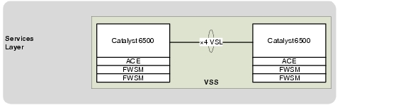
This configuration enables a unified control plane and allows both data planes to forward simultaneously. With VSS, the multi-chassis EtherChannel (MEC) capability is introduced, which allows a port channel to be defined across two physical switches.
Integrating VSS with Cisco DSN also increases the number of supported service modules per chassis from four to eight within a VSS domain, which enables an active-active highly available service chassis deployment.
For more information on VSS design see the following link:
http://www.cisco.com/en/US/docs/solutions/Enterprise/Campus/VSS30dg/campusVSS_DG.html
Example 2-16 VSS Configuration
switch virtual domain 100
switch mode virtual
switch 1 priority 150
no dual-active detection pagp
no dual-active detection bfd
mac-address use-virtual
!
interface Port-channel1
no switchport
no ip address
logging event link-status
logging event trunk-status
logging event bundle-status
load-interval 30
switch virtual link 1
mls qos trust cos
no mls qos channel-consistency
port-channel port hash-distribution adaptive
!
interface Port-channel2
no switchport
no ip address
logging event link-status
logging event trunk-status
logging event bundle-status
load-interval 30
switch virtual link 2
mls qos trust cos
no mls qos channel-consistency
port-channel port hash-distribution adaptive
!
interface TenGigabitEthernet1/3/5
description To EAST-VSS-A 2/3/5
no switchport
no ip address
logging event link-status
logging event trunk-status
logging event bundle-status
load-interval 30
mls qos trust cos
channel-group 1 mode on
!
interface TenGigabitEthernet1/3/6
description To EAST-VSS-A 2/3/6
no switchport
no ip address
logging event link-status
logging event trunk-status
logging event bundle-status
load-interval 30
mls qos trust cos
channel-group 1 mode on
!
interface TenGigabitEthernet1/6/4
description To EAST-VSS-A 2/6/4
no switchport
no ip address
logging event link-status
logging event trunk-status
logging event bundle-status
load-interval 30
mls qos trust cos
channel-group 1 mode on
!
interface TenGigabitEthernet1/6/5
description To EAST-VSS-A 2/6/5
no switchport
no ip address
logging event link-status
logging event trunk-status
logging event bundle-status
load-interval 30
mls qos trust cos
channel-group 1 mode on
!
interface GigabitEthernet1/6/2
no switchport
no ip address
logging event link-status
logging event trunk-status
logging event spanning-tree status
load-interval 30
dual-active fast-hello
end
!
interface TenGigabitEthernet2/3/5
description To EAST-VSS-A 1/3/5
no switchport
no ip address
logging event link-status
logging event trunk-status
logging event bundle-status
load-interval 30
mls qos trust cos
channel-group 2 mode on
!
interface TenGigabitEthernet2/3/6
description To EAST-VSS-A 1/3/6
no switchport
no ip address
logging event link-status
logging event trunk-status
logging event bundle-status
load-interval 30
mls qos trust cos
channel-group 2 mode on
!
interface TenGigabitEthernet2/6/4
description To EAST-VSS-A 1/6/4
no switchport
no ip address
logging event link-status
logging event trunk-status
logging event bundle-status
load-interval 30
mls qos trust cos
channel-group 2 mode on
!
interface TenGigabitEthernet2/6/5
description To EAST-VSS-A 1/6/5
no switchport
no ip address
logging event link-status
logging event trunk-status
logging event bundle-status
load-interval 30
mls qos trust cos
channel-group 2 mode on
!
interface GigabitEthernet2/6/2
no switchport
no ip address
logging event link-status
logging event trunk-status
logging event spanning-tree status
load-interval 30
dual-active fast-hello
end
Multi-Chassis EtherChannel (MEC)
For the Cisco VMDC 2.1 solution, the aggregation Nexus 7010 aggregation switches interconnect to the Cisco DSN through the MEC running in the VSS.
Figure 2-17 Multi-Channel EtherChannel Connections to DSN
Example 2-17 Catalyst 6500 DSN Configuration
interface Port-channel103
description L3 PC to EAST-DIST-A
no switchport
no ip address
logging event link-status
logging event bundle-status
load-interval 30
port-channel port hash-distribution adaptive
!
interface Port-channel104
description L3 PC to EAST-DIST-B
no switchport
no ip address
logging event link-status
logging event bundle-status
load-interval 30
port-channel port hash-distribution adaptive
!
interface TenGigabitEthernet1/2/1
description To DIST-N7010-A-EAST-DIST-A Eth 3/4
no switchport
no ip address
logging event bundle-status
load-interval 30
channel-group 103 mode active
!
interface TenGigabitEthernet1/3/1
description To DIST-N7010-B-EAST-DIST-B Eth 4/4
no switchport
no ip address
logging event bundle-status
load-interval 30
channel-group 104 mode active
!
interface TenGigabitEthernet2/2/1
description To DIST-N7010-A-EAST-DIST-A Eth 4/4
no switchport
no ip address
logging event bundle-status
load-interval 30
channel-group 103 mode active
!
interface TenGigabitEthernet2/3/1
description To DIST-N7010-B-EAST-DIST-B Eth 3/4
no switchport
no ip address
logging event bundle-status
load-interval 30
channel-group 104 mode active
Example 2-18 Nexus 7010 Configuration
! EAST-DIST-A
interface port-channel103
description L3 link to EAST-VSS
no lacp graceful-convergence
!
interface Ethernet3/4
description To EAST-VSS-A Ten1/2/1
channel-group 103 mode active
no shutdown
!
interface Ethernet4/4
description To EAST-VSS-A Ten2/2/1
channel-group 103 mode active
no shutdown
!
! EAST-DIST-B
!
interface port-channel104
description L3 link to EAST-VSS
no lacp graceful-convergence
!
interface Ethernet3/4
description To EAST-VSS-A Ten2/3/1
channel-group 104 mode active
no shutdown
!
interface Ethernet4/4
description To EAST-VSS-A Ten1/3/1
channel-group 104 mode active
no shutdown
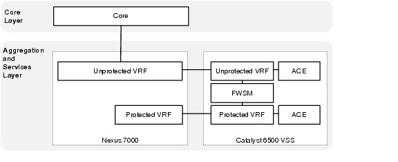
Virtual Routing and Forwarding (VRF)
IN Cisco VMDC 2.1, the DSN uses a dual-homed routed approach for data path connectivity to redundant aggregation layer switches. The FWSM, and ACE modules operate in routed mode. Each tenant is deployed with two VRFs: unprotected and protected. Routes propagate to all hops in a Layer 3 domain, and the VLANs used by the FW and ACE service modules are then mapped to the unprotected and protected VRFs. By default, communications between VRF instances are prevented to protect the privacy of each tenant as well as between tenant zones.
Figure 2-18 VRFs and DSN Interconnections
The following configurations are required for each zone:
Unprotected Zone VRF
•![]() VRF definition
VRF definition
•![]() Unprotected Loopback Interface
Unprotected Loopback Interface
•![]() Dot1q sub-interface to Aggregation A
Dot1q sub-interface to Aggregation A
•![]() Dot1q sub-interface to Aggregation B
Dot1q sub-interface to Aggregation B
•![]() Unprotected ACE VLAN
Unprotected ACE VLAN
•![]() FWSM Public side VLAN
FWSM Public side VLAN
•![]() OSPF routing process
OSPF routing process
•![]() Static route to Protected Zone subnet
Static route to Protected Zone subnet
•![]() Static routes to ACE VIP and SNAT subnets
Static routes to ACE VIP and SNAT subnets
Example 2-19 is an example unprotected VRF configuration.
Example 2-19 DSN Unprotected VRF Configuration
ip vrf T1U
description Tenant 1 Unprotected
rd 10.1.31.13:13
!
interface Loopback1
description RID for VRF T1U
ip vrf forwarding T1U
ip address 10.1.31.13 255.255.255.255
!
interface Port-channel103
description L3 PC to EAST-DIST-A
no switchport
no ip address
logging event link-status
logging event bundle-status
load-interval 30
port-channel port hash-distribution adaptive
!
interface Port-channel103.1
encapsulation dot1Q 3101
ip vrf forwarding T1U
ip address 10.1.28.46 255.255.255.252
ip ospf network point-to-point
!
interface Port-channel104
description L3 PC to EAST-DIST-B
!
interface Port-channel104.1
encapsulation dot1Q 3201
ip vrf forwarding T1U
ip address 10.1.28.50 255.255.255.252
ip ospf network point-to-point
!
interface Vlan211
description Tenant 1 ACE Unprotected VLAN
ip vrf forwarding T1U
ip address 10.1.28.129 255.255.255.248
load-interval 30
!
interface Vlan212
description Tenant 1 FWSM Outside Unprotected VLAN
ip vrf forwarding T1U
ip address 10.1.28.161 255.255.255.248
load-interval 30
!
router ospf 1 vrf T1U
router-id 10.1.31.13
log-adjacency-changes
auto-cost reference-bandwidth 100000
capability vrf-lite
area 0.0.0.10 nssa
timers throttle spf 10 100 5000
timers throttle lsa all 10 100 5000
timers lsa arrival 80
redistribute static subnets route-map T1U
passive-interface Vlan211
passive-interface Vlan212
network 10.1.28.44 0.0.0.3 area 0.0.0.10
network 10.1.28.48 0.0.0.3 area 0.0.0.10
network 10.1.28.128 0.0.0.7 area 0.0.0.10
network 10.1.28.160 0.0.0.7 area 0.0.0.10
network 10.1.31.13 0.0.0.0 area 0.0.0.10
!
ip route vrf T1U 10.1.24.0 255.255.255.0 10.1.28.130
ip route vrf T1U 10.1.26.0 255.255.255.0 10.1.28.130
ip route vrf T1U 10.1.32.0 255.255.224.0 10.1.28.163
!
route-map T1U permit 10
match ip address 101
!
access-list 101 permit ip 10.1.24.0 0.0.0.255 any
access-list 101 permit ip 10.1.26.0 0.0.0.255 any
access-list 101 permit ip 10.1.32.0 0.0.31.255 any
Protected Zone VRF
•![]() VRF definition
VRF definition
•![]() Unprotected Loopback Interface
Unprotected Loopback Interface
•![]() Dot1q sub-interface to Aggregation A
Dot1q sub-interface to Aggregation A
•![]() Dot1q sub-interface to Aggregation B
Dot1q sub-interface to Aggregation B
•![]() Protected ACE VLAN
Protected ACE VLAN
•![]() FWSM Private side VLAN
FWSM Private side VLAN
•![]() OSPF routing process
OSPF routing process
•![]() Default Static route to Unprotected Zone
Default Static route to Unprotected Zone
•![]() Static routes to ACE VIP and SNAT subnets
Static routes to ACE VIP and SNAT subnets
Example 2-20 is an example protected VRF configuration.
Example 2-20 DSN Protected VRF Configuration
ip vrf T1P
description Tenant 1 Protected
rd 10.1.63.13:13
!
interface Loopback101
description RID for VRF T1P
ip vrf forwarding T1P
ip address 10.1.63.13 255.255.255.255
!
interface Port-channel103
description L3 PC to EAST-DIST-A
no switchport
no ip address
logging event link-status
logging event bundle-status
load-interval 30
port-channel port hash-distribution adaptive
!
interface Port-channel103.101
encapsulation dot1Q 3301
ip vrf forwarding T1P
ip address 10.1.60.46 255.255.255.252
ip ospf network point-to-point
!
interface Port-channel104
description L3 PC to EAST-DIST-B
!
interface Port-channel104.101
encapsulation dot1Q 3401
ip vrf forwarding T1P
ip address 10.1.60.50 255.255.255.252
ip ospf network point-to-point
!
interface Vlan611
description Tenant 1 ACE Protected VLAN
ip vrf forwarding T1P
ip address 10.1.60.129 255.255.255.248
load-interval 30
!
interface Vlan612
description Tenant 1 FWSM Inside Protected VLAN
ip vrf forwarding T1P
ip address 10.1.60.161 255.255.255.248
load-interval 30
!
router ospf 101 vrf T1P
router-id 10.1.63.13
log-adjacency-changes
auto-cost reference-bandwidth 100000
capability vrf-lite
area 0.0.0.10 nssa default-information-originate
timers throttle spf 10 100 5000
timers throttle lsa all 10 100 5000
timers lsa arrival 80
redistribute static subnets route-map T1P
passive-interface Vlan611
passive-interface Vlan612
network 10.1.60.44 0.0.0.3 area 0.0.0.10
network 10.1.60.48 0.0.0.3 area 0.0.0.10
network 10.1.60.128 0.0.0.7 area 0.0.0.10
network 10.1.60.160 0.0.0.7 area 0.0.0.10
network 10.1.63.13 0.0.0.0 area 0.0.0.10
!
ip route vrf T1P 0.0.0.0 0.0.0.0 10.1.60.163
ip route vrf T1P 10.1.56.0 255.255.255.0 10.1.60.130
ip route vrf T1P 10.1.58.0 255.255.255.0 10.1.60.130
!
route-map T1P permit 10
match ip address 2101
!
access-list 2101 permit ip 10.1.56.0 0.0.0.255 any
access-list 2101 permit ip 10.1.58.0 0.0.0.255 any
Application Control Engine (ACE)
In the VMDC 2.1 solution, the Cisco ACE modules provide the following features:
•![]() Virtualization (context and resource allocation)
Virtualization (context and resource allocation)
•![]() Redundancy (active-active context failover)
Redundancy (active-active context failover)
•![]() Load balancing (protocols, stickiness)
Load balancing (protocols, stickiness)
•![]() Source NAT (static and dynamic NAT)
Source NAT (static and dynamic NAT)
The initial step to deploy the Cisco ACE module in the Cisco VMDC 2.1 network is to allocate the VLANs that the module will use from the DSN. The svclc vlan-group command is used to allocate VLANs to VLAN groups and to apply the VLAN groups to the Cisco ACE module use the svclc switch command.
Example 2-21 VLAN Allocation on the Cisco ACE Module (Catalyst 6500 VSS Configuration)
svclc multiple-vlan-interfaces
svclc switch 1 module 1 vlan-group 1,2
svclc switch 2 module 1 vlan-group 1,2
svclc vlan-group 1 3-6,32,40-43,132
svclc vlan-group 2 211,221,231,241,251,261,271,281,611,621,631,641,651,671
svclc vlan-group 2 681
After the VLANs are allocated, the contexts for the unprotected and protected tenant zones are created, as shown in Example 2-22, Example 2-23, Example 2-24, and Example 2-25.
Example 2-22 Example Tenant Contexts on the Cisco ACE Module (System Context Configuration)
EAST-ACE-A# show run
Generating configuration....
!
logging enable
logging timestamp
logging trap 7
logging supervisor 7
logging host 172.18.177.178 udp/514
!
peer hostname EAST-ACE-B
!
login timeout 0
line vty
session-limit 100
hostname EAST-ACE-A
boot system image:c6ace-t1k9-mz.A2_3_3.bin
!
clock timezone standard EST
!
class-map type management match-any REMOTE-ACCESS_ALL
description "Remote Management for ALL"
2 match protocol telnet any
3 match protocol ssh any
4 match protocol icmp any
5 match protocol http any
6 match protocol snmp any
7 match protocol https any
8 match protocol kalap-udp any
!
policy-map type management first-match REMOTE-MGMT
class REMOTE-ACCESS_ALL
permit
!
interface vlan 32
ip address 10.0.32.112 255.255.255.0
peer ip address 10.0.32.113 255.255.255.0
mtu 1500
service-policy input REMOTE-MGMT
no shutdown
!
ft interface vlan 132
ip address 10.0.132.112 255.255.255.0
peer ip address 10.0.132.113 255.255.255.0
no shutdown
!
ft peer 1
heartbeat interval 300
heartbeat count 10
ft-interface vlan 132
!
ft group 100
peer 1
priority 250
peer priority 200
associate-context Admin
inservice
!
ip route 0.0.0.0 0.0.0.0 10.0.32.1
!
context T1U
allocate-interface vlan 40
allocate-interface vlan 211
!
snmp-server community public group Network-Monitor
!
snmp-server enable traps slb serverfarm
snmp-server enable traps snmp coldstart
snmp-server enable traps virtual-context
snmp-server enable traps license
snmp-server enable traps slb vserver
snmp-server enable traps slb real
snmp-server enable traps syslog
snmp-server enable traps snmp authentication
snmp-server enable traps snmp linkup
snmp-server enable traps snmp linkdown
!
ft group 1
peer 1
priority 250
peer priority 200
associate-context T1U
inservice
!
Example 2-23 Example Tenant Contexts on the Cisco ACE Module (Unprotected Tenant Context Configuration)
EAST-ACE-A/T1U# show run
Generating configuration....
!
logging enable
logging timestamp
logging host 10.0.32.34 udp/514
!
access-list anyone line 10 extended permit ip any any
!
probe icmp PROBE_ICMP
interval 10
faildetect 2
passdetect interval 10
!
rserver host Avalanche-VM1
description Avalanche Server-1
ip address 10.1.3.230
inservice
rserver host Avalanche-VM2
description Avalanche Server-2
ip address 10.1.3.231
inservice
rserver host Avalanche-VM3
description Avalanche Server-3
ip address 10.1.3.232
inservice
!
serverfarm host Avalanche-sfarm1
predictor leastconns
rserver Avalanche-VM1
inservice
rserver Avalanche-VM2
inservice
rserver Avalanche-VM3
inservice
!
parameter-map type connection 5min_IDLE
slowstart
set timeout inactivity 300
!
class-map type management match-any REMOTE-ACCESS_ALL
description Remote Management for ALL
2 match protocol telnet any
3 match protocol ssh any
4 match protocol icmp any
5 match protocol http any
6 match protocol snmp any
7 match protocol https any
8 match protocol kalap-udp any
class-map match-any VIP_10.1.24.101_udp:53
2 match virtual-address 10.1.24.101 udp eq domain
class-map match-any VIP_10.1.24.102_tcp:80
2 match virtual-address 10.1.24.102 tcp eq www
!
policy-map type management first-match REMOTE-MGMT
class REMOTE-ACCESS_ALL
permit
!
policy-map type loadbalance first-match Avalanche-LBPM1
class class-default
serverfarm Avalanche-sfarm1
policy-map type loadbalance first-match Avalanche-LBPM2
class class-default
serverfarm Avalanche-sfarm1
!
policy-map multi-match Avalanche-VM-Policy
class VIP_10.1.24.101_udp:53
loadbalance vip inservice
loadbalance policy Avalanche-LBPM1
loadbalance vip icmp-reply active
nat dynamic 53 vlan 211
connection advanced-options 5min_IDLE
class VIP_10.1.24.102_tcp:80
loadbalance vip inservice
loadbalance policy Avalanche-LBPM2
loadbalance vip icmp-reply active
nat dynamic 80 vlan 211
connection advanced-options 5min_IDLE
!
interface vlan 40
ip address 10.0.40.5 255.255.255.0
alias 10.0.40.4 255.255.255.0
peer ip address 10.0.40.6 255.255.255.0
access-group input anyone
service-policy input REMOTE-MGMT
no shutdown
!
interface vlan 211
ip address 10.1.28.131 255.255.255.248
alias 10.1.28.130 255.255.255.248
peer ip address 10.1.28.132 255.255.255.248
access-group input anyone
nat-pool 53 10.1.26.1 10.1.26.1 netmask 255.255.255.0 pat
nat-pool 80 10.1.26.2 10.1.26.2 netmask 255.255.255.0 pat
service-policy input Avalanche-VM-Policy
service-policy input REMOTE-MGMT
no shutdown
!
ip route 0.0.0.0 0.0.0.0 10.1.28.129
ip route 10.0.32.0 255.255.240.0 10.0.40.1
ip route 172.18.0.0 255.255.0.0 10.0.40.1
!
snmp-server community public group Network-Monitor
!
snmp-server enable traps snmp authentication
snmp-server enable traps snmp linkup
snmp-server enable traps snmp linkdown
Example 2-24 Example Tenant Contexts on the Cisco ACE Module (System Context Configuration)
context T1P
allocate-interface vlan 40
allocate-interface vlan 611
!
ft group 101
peer 1
priority 250
peer priority 200
associate-context T1P
inservice
Example 2-25 Example Tenant Contexts on the Cisco ACE Module (Protected Tenant Context Configuration)
EAST-ACE-A/T1P# show run
!
Generating configuration....
!
logging enable
logging timestamp
logging host 10.0.32.34 udp/514
!
access-list anyone line 10 extended permit ip any any
!
probe icmp PROBE_ICMP
interval 10
faildetect 2
passdetect interval 10
!
rserver host Avalanche-VM1
description Avalanche Server-1
ip address 10.1.43.230
inservice
rserver host Avalanche-VM2
description Avalanche Server-2
ip address 10.1.43.231
inservice
rserver host Avalanche-VM3
description Avalanche Server-3
ip address 10.1.43.232
inservice
!
serverfarm host Avalanche-sfarm1
predictor leastconns
rserver Avalanche-VM1
inservice
rserver Avalanche-VM2
inservice
rserver Avalanche-VM3
inservice
!
parameter-map type connection 5min_IDLE
slowstart
set timeout inactivity 300
!
class-map type management match-any REMOTE-ACCESS_ALL
description Remote Management for ALL
2 match protocol telnet any
3 match protocol ssh any
4 match protocol icmp any
5 match protocol http any
6 match protocol snmp any
7 match protocol https any
8 match protocol kalap-udp any
class-map match-any VIP_10.1.56.101_udp:53
2 match virtual-address 10.1.56.101 udp eq domain
class-map match-any VIP_10.1.56.102_tcp:80
2 match virtual-address 10.1.56.102 tcp eq www
!
policy-map type management first-match REMOTE-MGMT
class REMOTE-ACCESS_ALL
permit
!
policy-map type loadbalance first-match Avalanche-LBPM1
class class-default
serverfarm Avalanche-sfarm1
policy-map type loadbalance first-match Avalanche-LBPM2
class class-default
serverfarm Avalanche-sfarm1
!
policy-map multi-match Avalanche-VM-Policy
class VIP_10.1.56.101_udp:53
loadbalance vip inservice
loadbalance policy Avalanche-LBPM1
loadbalance vip icmp-reply active
nat dynamic 53 vlan 611
connection advanced-options 5min_IDLE
class VIP_10.1.56.102_tcp:80
loadbalance vip inservice
loadbalance policy Avalanche-LBPM2
loadbalance vip icmp-reply active
nat dynamic 80 vlan 611
connection advanced-options 5min_IDLE
!
interface vlan 40
ip address 10.0.40.101 255.255.255.0
alias 10.0.40.100 255.255.255.0
peer ip address 10.0.40.102 255.255.255.0
access-group input anyone
service-policy input REMOTE-MGMT
no shutdown
interface vlan 611
ip address 10.1.60.131 255.255.255.248
alias 10.1.60.130 255.255.255.248
peer ip address 10.1.60.132 255.255.255.248
access-group input anyone
nat-pool 53 10.1.58.1 10.1.58.1 netmask 255.255.255.0 pat
nat-pool 80 10.1.58.2 10.1.58.2 netmask 255.255.255.0 pat
service-policy input Avalanche-VM-Policy
service-policy input REMOTE-MGMT
no shutdown
!
ip route 0.0.0.0 0.0.0.0 10.1.60.129
ip route 10.0.32.0 255.255.240.0 10.0.40.1
ip route 172.18.0.0 255.255.0.0 10.0.40.1
!
snmp-server community public group Network-Monitor
!
snmp-server enable traps snmp authentication
snmp-server enable traps snmp linkup
snmp-server enable traps snmp linkdown
Firewall Services Module (FWSM)
In the Cisco VMDC 2.1 solution, the Cisco FWSM provides the following features:
•![]() Virtualization (context and resource allocation)
Virtualization (context and resource allocation)
•![]() Redundancy (active-active context failover)
Redundancy (active-active context failover)
•![]() Security and inspection
Security and inspection
•![]() URL filtering
URL filtering
•![]() Protocol inspection
Protocol inspection
The Cisco FWSM is deployed similar to the ACE module by allocating the VLANs that the module uses from the DSN. The svclc vlan-group command assigns VLANs to VLAN groups. To apply the VLAN groups to the Cisco FWSM module, use the firewall switch command.
Example 2-26 VLAN Allocation on the Cisco FWSM (Catalyst 6500 VSS Configuration)
svclc vlan-group 1 3-6,32,40-43,132
svclc vlan-group 3 212,222,232,242,252,262,272,282,612,622,632,642,652,662
svclc vlan-group 3 672,682
firewall multiple-vlan-interfaces
firewall switch 1 module 4 vlan-group 1,3
firewall switch 1 module 7 vlan-group 1
firewall switch 2 module 4 vlan-group 1,3
firewall switch 2 module 7 vlan-group 1
After the VLANs are allocated, the context for each tenant is created. The FWSM tenant context can be set up in either routed or transparent mode.
The following configurations are required and there are some differences depending on which mode is chosen:
Routed Mode
•![]() FWSM Public side VLAN
FWSM Public side VLAN
•![]() FWSM Private side VLAN
FWSM Private side VLAN
•![]() Static route to Protected Zone subnet
Static route to Protected Zone subnet
•![]() Default Static route to Unprotected Zone
Default Static route to Unprotected Zone
•![]() Management VLAN interface
Management VLAN interface
•![]() Static routes for management network destinations
Static routes for management network destinations
•![]() Security Policy
Security Policy
Example 2-27 Example Tenant 1 Routed Context on the Cisco FWSM (System Context Configuration)
changeto system
!
EAST-FWSM-A#show run
: Saved
:
FWSM Version 4.1(4) <system>
!
resource acl-partition 12
terminal width 511
hostname EAST-FWSM-A
hostname secondary EAST-FWSM-B
enable password 9D8jmmmgkfNZLETh encrypted
!
interface Vlan3
description LAN Failover Interface
!
interface Vlan4
description STATE Failover Interface
!
interface Vlan32
!
interface Vlan42
description 10.0.42.0_EAST-FW Failover-Group1 VLAN
!
interface Vlan43
description 10.0.43.0_EAST-FW Failover-Group2 VLAN
!
interface Vlan189
!
interface Vlan190
!
interface Vlan212
!
interface Vlan612
!
passwd 9D8jmmmgkfNZLETh encrypted
class default
limit-resource ASDM 5
limit-resource IPSec 5
limit-resource Mac-addresses 65535
limit-resource SSH 5
limit-resource Telnet 5
limit-resource All 0
!
banner motd " Unauthorized access will be prosecuted to fullest extent of the law "
no ftp mode passive
no pager
failover
failover lan unit primary
failover lan interface FT_LINK Vlan3
failover polltime unit 1 holdtime 3
failover replication http
failover link FT_STATE Vlan4
failover interface ip FT_LINK 3.1.1.1 255.255.255.0 standby 3.1.1.2
failover interface ip FT_STATE 4.1.1.1 255.255.255.0 standby 4.1.1.2
failover group 1
preempt
replication http
polltime interface 3
failover group 2
secondary
preempt
replication http
polltime interface 3
asdm history enable
arp timeout 14400
console timeout 30
admin-context admin
context admin
description Admin Context
allocate-interface Vlan189
allocate-interface Vlan32
config-url disk:/admin.cfg
join-failover-group 1
!
context T1
description Tenant1 FW Context
member default
allocate-interface Vlan189
allocate-interface Vlan212
allocate-interface Vlan42
allocate-interface Vlan612
config-url disk:/T1.cfg
join-failover-group 1
!
prompt hostname context
Cryptochecksum:35e0f865a03ed4222a7a85f0384058ab
: end
Example 2-28 Example Tenant 1 Routed Context on the Cisco FWSM (Tenant Context Configuration)
changeto context T1
!
EAST-FWSM-A/T1# show run
: Saved
:
FWSM Version 4.1(4) <context>
!
terminal width 511
hostname T1
enable password 9D8jmmmgkfNZLETh encrypted
names
dns-guard
!
interface Vlan189
description Dummy Vlan for Telnet support
nameif dummy
security-level 0
no ip address
!
interface Vlan212
nameif outside
security-level 10
ip address 10.1.28.163 255.255.255.248 standby 10.1.28.164
!
interface Vlan42
nameif management
security-level 1
ip address 10.0.42.4 255.255.255.0 standby 10.0.42.5
!
interface Vlan612
nameif inside
security-level 100
ip address 10.1.60.163 255.255.255.248 standby 10.1.60.164
!
passwd 9D8jmmmgkfNZLETh encrypted
access-list inside-acl extended permit ip any any
access-list inside-acl extended permit udp any any
access-list inside-acl extended permit tcp any any
access-list inside-acl extended permit icmp any any
access-list outside-acl extended permit ip any any
access-list outside-acl extended permit udp any any
access-list outside-acl extended permit tcp any any
access-list outside-acl extended permit icmp any any
access-list mgmt-acl extended permit icmp any any
access-list mgmt-acl extended permit tcp any any
access-list mgmt-acl extended permit udp any any
access-list mgmt-acl extended permit ip any any
pager lines 24
logging enable
logging timestamp
logging host management 10.0.32.34
mtu outside 1500
mtu management 1500
mtu inside 1500
mtu dummy 1500
icmp permit any outside
icmp permit any management
icmp permit any inside
no asdm history enable
arp timeout 14400
access-group outside-acl in interface outside per-user-override
access-group mgmt-acl in interface management
access-group mgmt-acl out interface management
access-group inside-acl in interface inside per-user-override
route outside 10.1.0.0 255.255.224.0 10.1.28.161 1
route outside 0.0.0.0 0.0.0.0 10.1.28.161 1
route management 172.18.0.0 255.255.0.0 10.0.42.1 1
route management 10.0.32.0 255.255.240.0 10.0.42.1 1
route management 10.0.14.0 255.255.255.0 10.0.42.1 1
route inside 10.1.32.0 255.255.224.0 10.1.60.161 1
timeout xlate 3:00:00
timeout conn 1:00:00 half-closed 0:10:00 udp 0:02:00 icmp 0:00:02
timeout sunrpc 0:10:00 h323 1:00:00 h225 1:00:00 mgcp 0:05:00
timeout mgcp-pat 0:05:00 sip 0:30:00 sip_media 0:02:00
timeout sip-invite 0:03:00 sip-disconnect 0:02:00
timeout pptp-gre 0:02:00
timeout uauth 0:05:00 absolute
username admin password Km9FNismGAXIMvno encrypted
snmp-server host management 172.18.177.140 community public
no snmp-server location
no snmp-server contact
snmp-server community public
snmp-server enable traps snmp authentication linkup linkdown coldstart
telnet 10.0.14.0 255.255.255.0 management
telnet 172.18.0.0 255.255.0.0 management
telnet 10.0.32.0 255.255.240.0 management
telnet 172.18.0.0 255.255.0.0 dummy
telnet 10.0.14.0 255.255.255.0 dummy
telnet timeout 5
ssh timeout 5
class-map inspection_default
match default-inspection-traffic
!
policy-map global_policy
class inspection_default
inspect dns maximum-length 512
inspect ftp
inspect h323 h225
inspect h323 ras
inspect netbios
inspect rsh
inspect skinny
inspect smtp
inspect sqlnet
inspect sunrpc
inspect tftp
inspect sip
inspect xdmcp
!
service-policy global_policy global
Cryptochecksum:53c6ea585e6b768b57aa57053c4ad759
: end
Transparent Mode
•![]() FWSM Public side VLAN
FWSM Public side VLAN
•![]() FWSM Private side VLAN
FWSM Private side VLAN
•![]() Bridge Group
Bridge Group
•![]() Management IP address on directly connected subnet
Management IP address on directly connected subnet
•![]() Security Policy
Security Policy
Example 2-29 Example Tenant 1 Transparent Context on the Cisco FWSM (System Context Configuration)
changeto system
EAST-FWSM-A#show run
: Saved
:
FWSM Version 4.1(4) <system>
!
resource acl-partition 12
terminal width 511
hostname EAST-FWSM-A
hostname secondary EAST-FWSM-B
enable password 9D8jmmmgkfNZLETh encrypted
!
interface Vlan3
description LAN Failover Interface
!
interface Vlan4
description STATE Failover Interface
!
interface Vlan32
!
interface Vlan42
description 10.0.42.0_EAST-FW Failover-Group1 VLAN
!
interface Vlan43
description 10.0.43.0_EAST-FW Failover-Group2 VLAN
!
interface Vlan189
!
interface Vlan212
!
interface Vlan612
!
!
passwd 9D8jmmmgkfNZLETh encrypted
class default
limit-resource ASDM 5
limit-resource IPSec 5
limit-resource Mac-addresses 65535
limit-resource SSH 5
limit-resource Telnet 5
limit-resource All 0
!
banner motd " Unauthorized access will be prosecuted to fullest extent of law "
no ftp mode passive
no pager
failover
failover lan unit primary
failover lan interface FT_LINK Vlan3
failover polltime unit 1 holdtime 3
failover replication http
failover link FT_STATE Vlan4
failover interface ip FT_LINK 3.1.1.1 255.255.255.0 standby 3.1.1.2
failover interface ip FT_STATE 4.1.1.1 255.255.255.0 standby 4.1.1.2
failover group 1
preempt
replication http
polltime interface 3
failover group 2
secondary
preempt
replication http
polltime interface 3
asdm history enable
arp timeout 14400
console timeout 30
admin-context admin
context admin
description Admin Context
allocate-interface Vlan189
allocate-interface Vlan32
config-url disk:/admin.cfg
join-failover-group 1
!
context T1-TRANSPARENT
allocate-interface Vlan212
allocate-interface Vlan611
config-url disk:/T1-TRANS.cfg
join-failover-group 1
!
prompt hostname context
Cryptochecksum:35e0f865a03ed4222a7a85f0384058ab
: end
Example 2-30 Example Tenant 1 Transparent Context on the Cisco FWSM (Tenant Context Configuration)
FWSM Version 4.1(4) <context>
!
firewall transparent
hostname T1-TRANSPARENT
enable password Y3x.5q9PkPeHCZWV encrypted
names
dns-guard
!
interface Vlan212
nameif outside
bridge-group 1
security-level 10
!
interface Vlan612
nameif inside
bridge-group 1
security-level 100
!
interface BVI1
ip address 10.1.28.163 255.255.255.248 standby 10.1.28.164
!
passwd 2KFQnbNIdI.2KYOU encrypted
access-list inside extended permit icmp any any
access-list inside extended permit ip any any
access-list outside extended permit ip any any
access-list outside extended permit icmp any any
pager lines 24
mtu inside 1500
mtu outside 1500
icmp permit any inside
icmp permit any outside
no asdm history enable
arp timeout 14400
access-group inside in interface inside
access-group outside in interface outside
route outside 0.0.0.0 0.0.0.0 10.1.28.161 1
timeout xlate 3:00:00
timeout conn 1:00:00 half-closed 0:10:00 udp 0:02:00 icmp 0:00:02
timeout sunrpc 0:10:00 h323 1:00:00 h225 1:00:00 mgcp 0:05:00
timeout mgcp-pat 0:05:00 sip 0:30:00 sip_media 0:02:00
timeout sip-invite 0:03:00 sip-disconnect 0:02:00
timeout pptp-gre 0:02:00
timeout uauth 0:05:00 absolute
username administrator password Wzd8zAKhRzs.IrRP encrypted privilege 15
aaa authentication ssh console LOCAL
aaa authentication enable console LOCAL
aaa authentication http console LOCAL
http server enable
http 0.0.0.0 0.0.0.0 inside
no snmp-server location
no snmp-server contact
snmp-server enable traps snmp authentication linkup linkdown coldstart
telnet timeout 5
ssh 0.0.0.0 0.0.0.0 inside
ssh timeout 5
!
class-map inspection_default
match default-inspection-traffic
!
policy-map global_policy
class inspection_default
inspect dns maximum-length 512
inspect ftp
inspect h323 h225
inspect h323 ras
inspect sunrpc
inspect rsh
inspect smtp
inspect sqlnet
inspect skinny
inspect xdmcp
inspect sip
inspect netbios
inspect tftp
!
service-policy global_policy global
Cryptochecksum:00000000000000000000000000000000
: end
Services Deployment Guidelines
The following services deployment guidelines were identified.
VSS
•![]() It is important to size the VSS VSL accordingly. The total bandwidth of the VSL should be equal to the total amount of uplink traffic coming into a single chassis.
It is important to size the VSS VSL accordingly. The total bandwidth of the VSL should be equal to the total amount of uplink traffic coming into a single chassis.
Port-Channel
•![]() On the Catalyst 6500 DSN configure the adaptive port channel hash-distribution algorithm. This configuration optimizes the behavior of the port ASICs of member ports upon the failure of a single member.
On the Catalyst 6500 DSN configure the adaptive port channel hash-distribution algorithm. This configuration optimizes the behavior of the port ASICs of member ports upon the failure of a single member.
•![]() By default on the Nexus 7000, LACP graceful convergence is enabled. It should be disabled when connecting to the Catalyst 6500 DSN as the graceful failover defaults may delay the time taken for a disabled port to be brought down or cause traffic from the peer to be lost.
By default on the Nexus 7000, LACP graceful convergence is enabled. It should be disabled when connecting to the Catalyst 6500 DSN as the graceful failover defaults may delay the time taken for a disabled port to be brought down or cause traffic from the peer to be lost.
OSPF
•![]() Use OSPF point-to-point mode on the 10G Ethernet links so the adjacency is always formed with the neighbor. There is no DR/BDR election in a point-to-point mode. This configuration gives the flexibility to configure separate OSPF cost per point-to-point neighbor.
Use OSPF point-to-point mode on the 10G Ethernet links so the adjacency is always formed with the neighbor. There is no DR/BDR election in a point-to-point mode. This configuration gives the flexibility to configure separate OSPF cost per point-to-point neighbor.
•![]() OSPF hello and hold timers are left at default values.
OSPF hello and hold timers are left at default values.
•![]() Use OSPF manual link costs on Layer 3 port channels to prevent cost changes when member links fail or are added to the bundle.
Use OSPF manual link costs on Layer 3 port channels to prevent cost changes when member links fail or are added to the bundle.
•![]() OSPF throttle timer tuning could be further tuned to achieve faster convergence.
OSPF throttle timer tuning could be further tuned to achieve faster convergence.
•![]() OSPF NSSA is used to allow importing of the static routes into the OSPF routing domain and also to limits the number of routes advertised from the aggregation layer to the services layer.
OSPF NSSA is used to allow importing of the static routes into the OSPF routing domain and also to limits the number of routes advertised from the aggregation layer to the services layer.
FWSM
•![]() Routed mode allows the most deployment flexibility.
Routed mode allows the most deployment flexibility.
•![]() prune VLANs
prune VLANs
ACE
•![]() prune VLANs
prune VLANs
Traffic Flow Optimization
•![]() To optimize traffic flows within the DSN, keep all active ACE and FWSM contexts for a single tenant on the same DSN chassis. This limits the inter-module traffic required to traverse the VSL.
To optimize traffic flows within the DSN, keep all active ACE and FWSM contexts for a single tenant on the same DSN chassis. This limits the inter-module traffic required to traverse the VSL.
•![]() Use Layer 3 and Layer 4 information to achieve optimum link utilization when using EtherChannel interconnections.
Use Layer 3 and Layer 4 information to achieve optimum link utilization when using EtherChannel interconnections.
Access Layer (Nexus 5000)
The Cisco VMDC 2.1 access layer is deployed using the Cisco Nexus 5000 next generation datacenter switching platform. The Cisco Nexus 5000 Series Switches are ideal for enterprise-class data center server access layer.
The Cisco VMDC 2.1 access layer provides connectivity for the UCS end nodes residing in the pod.
Nexus 5000 Module Details
The Cisco VMDC 2.1 solution includes the following Nexus 5000-compatible modules:
Example 2-31 Nexus 5010 A
EAST-N5020-A# show module
Mod Ports Module-Type Model Status
--- ----- -------------------------------- ---------------------- ------------
1 40 40x10GE/Supervisor N5K-C5020P-BF-SUP active *
2 8 8x1/2/4G FC Module N5K-M1008 ok
3 8 4x10GE + 4x1/2/4G FC Module N5K-M1404 ok
Mod Sw Hw World-Wide-Name(s) (WWN)
--- -------------- ------ --------------------------------------------------
1 5.0(3)N1(1a) 1.3 --
2 5.0(3)N1(1a) 1.0 f8:8b:b7:62:2f:6c:69:62 to 70:6c:61:74:66:6f:72:6d
3 5.0(3)N1(1a) 0.103 74:20:6f:70:65:6e:20:73 to 65:00:6c:69:62:77:77:6e
Mod MAC-Address(es) Serial-Num
--- -------------------------------------- ----------
1 0005.9b21.0c88 to 0005.9b21.0caf JAF1421CTFC
2 0005.9b21.0cb0 to 0005.9b21.0cb7 JAF1308AJSA
3 0005.9b21.0cb8 to 0005.9b21.0cbf JAB1210017H
Example 2-32 Nexus 5010 B
EAST-N5020-B# show module
Mod Ports Module-Type Model Status
--- ----- -------------------------------- ---------------------- ------------
1 40 40x10GE/Supervisor N5K-C5020P-BF-SUP active *
2 8 8x1/2/4G FC Module N5K-M1008 ok
3 8 4x10GE + 4x1/2/4G FC Module N5K-M1404 ok
Mod Sw Hw World-Wide-Name(s) (WWN)
--- -------------- ------ --------------------------------------------------
1 5.0(3)N1(1a) 1.3 --
2 5.0(3)N1(1a) 1.0 f8:8b:b7:62:2f:6c:69:62 to 70:6c:61:74:66:6f:72:6d
3 5.0(3)N1(1a) 1.0 74:20:6f:70:65:6e:20:73 to 65:00:6c:69:62:77:77:6e
Mod MAC-Address(es) Serial-Num
--- -------------------------------------- ----------
1 0005.9b20.72c8 to 0005.9b20.72ef JAF1421ANAL
2 0005.9b20.72f0 to 0005.9b20.72f7 JAF1327AAFM
3 0005.9b20.72f8 to 0005.9b20.72ff JAF1418DRSG
vPC Implementation
As discussed in Virtual PortChannel Implementation (vPC), deploying vPCs in both the aggregation and access layers enable the full, cross-sectional bandwidth utilization (80Gbps) between the aggregation and access layers (depicted in Figure 2-19).
Figure 2-19 vPC Implementation in Cisco VMDC 2.1
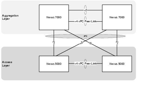
The vPC domain includes both vPC peer devices, the vPC peer keepalive link, the vPC peer link, and all the PortChannels in the vPC domain connected to the downstream device.
Example 2-33 Example vPC Configurations between Access and Aggregation (Nexus 5000 A Configuration)
! STP specific configuration
!
spanning-tree pathcost method long
!
! configure vPC
!
vpc domain 101
role priority 16000
peer-keepalive destination 10.0.32.105 source 10.0.32.104
auto-recovery
!
interface port-channel1
description vPC Peer Link to EAST-N5020-B
switchport mode trunk
vpc peer-link
  switchport trunk allowed vlan
14,32-48,50,52,56,60,99,193-194,211-215,221-225,231-235,241-245,251-255,261-265,271-275,28
1-285,291-293,301-303,311-313,321-323,331-333,341-343,351-353,361-363,371-373,381-383,391-
393,401-403,411-413,421-423,431-433,441-443,451-453,461-463,471-473,481-483,491-493,501-50
3,511-513,521-523,611-613,621-623,631-633,641-643,651-653,661-663,671-673,681-683,691-693,
701-703,711-713,721-723,731-733,741-743,751-753,761-763,771-773,781-783,791-793,801-803,81
1-813,821-823,831-833,841-843,851-853,861-863,871-873,881-883,891-893,901-903,911-913,921-
923
spanning-tree port type network
!
interface port-channel202
description vpc to N7k
switchport mode trunk
vpc 202
  switchport trunk allowed vlan
211-213,221-223,231-233,241-243,251-253,261-263,271-273,281-283,291-293,301-303,311-313,32
1-323,331-333,341-343,351-353,361-363,371-373,381-383,391-393,401-403,411-413,421-423,431-
433,441-443,451-453,461-463,471-473,481-483,491-493,501-503,511-513,521-523,611-613,621-62
3,631-633,641-643,651-653,661-663,671-673,681-683,691-693,701-703,711-713,721-723,731-733,
741-743,751-753,761-763,771-773,781-783,791-793,801-803,811-813,821-823,831-833,841-843,85
1-853,861-863,871-873,881-883,891-893,901-903,911-913,921-923
spanning-tree port type normal
!
interface Ethernet1/17
switchport mode trunk
  switchport trunk allowed vlan
14,32-48,50,52,56,60,99,193-194,211-215,221-225,231-235,241-245,251-255,261-265,271-275,28
1-285,291-293,301-303,311-313,321-323,331-333,341-343,351-353,361-363,371-373,381-383,391-
393,401-403,411-413,421-423,431-433,441-443,451-453,461-463,471-473,481-483,491-493,501-50
3,511-513,521-523,611-613,621-623,631-633,641-643,651-653,661-663,671-673,681-683,691-693,
701-703,711-713,721-723,731-733,741-743,751-753,761-763,771-773,781-783,791-793,801-803,81
1-813,821-823,831-833,841-843,851-853,861-863,871-873,881-883,891-893,901-903,911-913,921-
923
channel-group 1 mode active
!
interface Ethernet1/18
switchport mode trunk
  switchport trunk allowed vlan
14,32-48,50,52,56,60,99,193-194,211-215,221-225,231-235,241-245,251-255,261-265,271-275,28
1-285,291-293,301-303,311-313,321-323,331-333,341-343,351-353,361-363,371-373,381-383,391-
393,401-403,411-413,421-423,431-433,441-443,451-453,461-463,471-473,481-483,491-493,501-50
3,511-513,521-523,611-613,621-623,631-633,641-643,651-653,661-663,671-673,681-683,691-693,
701-703,711-713,721-723,731-733,741-743,751-753,761-763,771-773,781-783,791-793,801-803,81
1-813,821-823,831-833,841-843,851-853,861-863,871-873,881-883,891-893,901-903,911-913,921-
923
channel-group 1 mode active
!
interface Ethernet1/19
switchport mode trunk
  switchport trunk allowed vlan
14,32-48,50,52,56,60,99,193-194,211-215,221-225,231-235,241-245,251-255,261-265,271-275,28
1-285,291-293,301-303,311-313,321-323,331-333,341-343,351-353,361-363,371-373,381-383,391-
393,401-403,411-413,421-423,431-433,441-443,451-453,461-463,471-473,481-483,491-493,501-50
3,511-513,521-523,611-613,621-623,631-633,641-643,651-653,661-663,671-673,681-683,691-693,
701-703,711-713,721-723,731-733,741-743,751-753,761-763,771-773,781-783,791-793,801-803,81
1-813,821-823,831-833,841-843,851-853,861-863,871-873,881-883,891-893,901-903,911-913,921-
923
channel-group 1 mode active
!
interface Ethernet1/20
switchport mode trunk
  switchport trunk allowed vlan
14,32-48,50,52,56,60,99,193-194,211-215,221-225,231-235,241-245,251-255,261-265,271-275,28
1-285,291-293,301-303,311-313,321-323,331-333,341-343,351-353,361-363,371-373,381-383,391-
393,401-403,411-413,421-423,431-433,441-443,451-453,461-463,471-473,481-483,491-493,501-50
3,511-513,521-523,611-613,621-623,631-633,641-643,651-653,661-663,671-673,681-683,691-693,
701-703,711-713,721-723,731-733,741-743,751-753,761-763,771-773,781-783,791-793,801-803,81
1-813,821-823,831-833,841-843,851-853,861-863,871-873,881-883,891-893,901-903,911-913,921-
923
channel-group 1 mode active
!
interface Ethernet1/29
switchport mode trunk
  switchport trunk allowed vlan
211-213,221-223,231-233,241-243,251-253,261-263,271-273,281-283,291-293,301-303,311-313,32
1-323,331-333,341-343,351-353,361-363,371-373,381-383,391-393,401-403,411-413,421-423,431-
433,441-443,451-453,461-463,471-473,481-483,491-493,501-503,511-513,521-523,611-613,621-62
3,631-633,641-643,651-653,661-663,671-673,681-683,691-693,701-703,711-713,721-723,731-733,
741-743,751-753,761-763,771-773,781-783,791-793,801-803,811-813,821-823,831-833,841-843,85
1-853,861-863,871-873,881-883,891-893,901-903,911-913,921-923
channel-group 202 mode active
!
interface Ethernet1/30
switchport mode trunk
  switchport trunk allowed vlan
211-213,221-223,231-233,241-243,251-253,261-263,271-273,281-283,291-293,301-303,311-313,32
1-323,331-333,341-343,351-353,361-363,371-373,381-383,391-393,401-403,411-413,421-423,431-
433,441-443,451-453,461-463,471-473,481-483,491-493,501-503,511-513,521-523,611-613,621-62
3,631-633,641-643,651-653,661-663,671-673,681-683,691-693,701-703,711-713,721-723,731-733,
741-743,751-753,761-763,771-773,781-783,791-793,801-803,811-813,821-823,831-833,841-843,85
1-853,861-863,871-873,881-883,891-893,901-903,911-913,921-923
channel-group 202 mode active
!
interface Ethernet1/31
switchport mode trunk
  switchport trunk allowed vlan
211-213,221-223,231-233,241-243,251-253,261-263,271-273,281-283,291-293,301-303,311-313,32
1-323,331-333,341-343,351-353,361-363,371-373,381-383,391-393,401-403,411-413,421-423,431-
433,441-443,451-453,461-463,471-473,481-483,491-493,501-503,511-513,521-523,611-613,621-62
3,631-633,641-643,651-653,661-663,671-673,681-683,691-693,701-703,711-713,721-723,731-733,
741-743,751-753,761-763,771-773,781-783,791-793,801-803,811-813,821-823,831-833,841-843,85
1-853,861-863,871-873,881-883,891-893,901-903,911-913,921-923
channel-group 202 mode active
!
interface Ethernet1/32
switchport mode trunk
  switchport trunk allowed vlan
211-213,221-223,231-233,241-243,251-253,261-263,271-273,281-283,291-293,301-303,311-313,32
1-323,331-333,341-343,351-353,361-363,371-373,381-383,391-393,401-403,411-413,421-423,431-
433,441-443,451-453,461-463,471-473,481-483,491-493,501-503,511-513,521-523,611-613,621-62
3,631-633,641-643,651-653,661-663,671-673,681-683,691-693,701-703,711-713,721-723,731-733,
741-743,751-753,761-763,771-773,781-783,791-793,801-803,811-813,821-823,831-833,841-843,85
1-853,861-863,871-873,881-883,891-893,901-903,911-913,921-923
channel-group 202 mode active
!
! set mac aging time to match aggregaton
!
mac address-table aging-time 1800
Example 2-34 Example vPC Configurations between Access and Aggregation (Nexus 5000 B Configuration)
! STP specific configuration
!
spanning-tree pathcost method long
!
! configure vPC
!
vpc domain 101
role priority 32000
peer-keepalive destination 10.0.32.104 source 10.0.32.105
auto-recovery
!
interface port-channel1
description vPC Peer Link to EAST-N5020-A
switchport mode trunk
vpc peer-link
    switchport trunk allowed vlan
14,32-48,50,52,56,60,99,193-194,211-215,221-225,231-235,241-245,251-255,261-265,271-275,28
1-285,291-293,301-303,311-313,321-323,331-333,341-343,351-353,361-363,371-373,381-383,391-
393,401-403,411-413,421-423,431-433,441-443,451-453,461-463,471-473,481-483,491-493,501-50
3,511-513,521-523,611-613,621-623,631-633,641-643,651-653,661-663,671-673,681-683,691-693,
701-703,711-713,721-723,731-733,741-743,751-753,761-763,771-773,781-783,791-793,801-803,81
1-813,821-823,831-833,841-843,851-853,861-863,871-873,881-883,891-893,901-903,911-913,921-
923
spanning-tree port type network
!
interface port-channel202
description vpc to N7k
switchport mode trunk
vpc 202
  switchport trunk allowed vlan
211-213,221-223,231-233,241-243,251-253,261-263,271-273,281-283,291-293,301-303,311-313,32
1-323,331-333,341-343,351-353,361-363,371-373,381-383,391-393,401-403,411-413,421-423,431-
433,441-443,451-453,461-463,471-473,481-483,491-493,501-503,511-513,521-523,611-613,621-62
3,631-633,641-643,651-653,661-663,671-673,681-683,691-693,701-703,711-713,721-723,731-733,
741-743,751-753,761-763,771-773,781-783,791-793,801-803,811-813,821-823,831-833,841-843,85
1-853,861-863,871-873,881-883,891-893,901-903,911-913,921-923
spanning-tree port type normal
!
interface Ethernet1/17
switchport mode trunk
  switchport trunk allowed vlan
14,32-48,50,52,56,60,99,193-194,211-215,221-225,231-235,241-245,251-255,261-265,271-275,28
1-285,291-293,301-303,311-313,321-323,331-333,341-343,351-353,361-363,371-373,381-383,391-
393,401-403,411-413,421-423,431-433,441-443,451-453,461-463,471-473,481-483,491-493,501-50
3,511-513,521-523,611-613,621-623,631-633,641-643,651-653,661-663,671-673,681-683,691-693,
701-703,711-713,721-723,731-733,741-743,751-753,761-763,771-773,781-783,791-793,801-803,81
1-813,821-823,831-833,841-843,851-853,861-863,871-873,881-883,891-893,901-903,911-913,921-
923
channel-group 1 mode active
!
interface Ethernet1/18
switchport mode trunk
  switchport trunk allowed vlan
14,32-48,50,52,56,60,99,193-194,211-215,221-225,231-235,241-245,251-255,261-265,271-275,28
1-285,291-293,301-303,311-313,321-323,331-333,341-343,351-353,361-363,371-373,381-383,391-
393,401-403,411-413,421-423,431-433,441-443,451-453,461-463,471-473,481-483,491-493,501-50
3,511-513,521-523,611-613,621-623,631-633,641-643,651-653,661-663,671-673,681-683,691-693,
701-703,711-713,721-723,731-733,741-743,751-753,761-763,771-773,781-783,791-793,801-803,81
1-813,821-823,831-833,841-843,851-853,861-863,871-873,881-883,891-893,901-903,911-913,921-
923
channel-group 1 mode active
!
interface Ethernet1/19
switchport mode trunk
  switchport trunk allowed vlan
14,32-48,50,52,56,60,99,193-194,211-215,221-225,231-235,241-245,251-255,261-265,271-275,28
1-285,291-293,301-303,311-313,321-323,331-333,341-343,351-353,361-363,371-373,381-383,391-
393,401-403,411-413,421-423,431-433,441-443,451-453,461-463,471-473,481-483,491-493,501-50
3,511-513,521-523,611-613,621-623,631-633,641-643,651-653,661-663,671-673,681-683,691-693,
701-703,711-713,721-723,731-733,741-743,751-753,761-763,771-773,781-783,791-793,801-803,81
1-813,821-823,831-833,841-843,851-853,861-863,871-873,881-883,891-893,901-903,911-913,921-
923
channel-group 1 mode active
!
interface Ethernet1/20
switchport mode trunk
  switchport trunk allowed vlan
14,32-48,50,52,56,60,99,193-194,211-215,221-225,231-235,241-245,251-255,261-265,271-275,28
1-285,291-293,301-303,311-313,321-323,331-333,341-343,351-353,361-363,371-373,381-383,391-
393,401-403,411-413,421-423,431-433,441-443,451-453,461-463,471-473,481-483,491-493,501-50
3,511-513,521-523,611-613,621-623,631-633,641-643,651-653,661-663,671-673,681-683,691-693,
701-703,711-713,721-723,731-733,741-743,751-753,761-763,771-773,781-783,791-793,801-803,81
1-813,821-823,831-833,841-843,851-853,861-863,871-873,881-883,891-893,901-903,911-913,921-
923
channel-group 1 mode active
!
interface Ethernet1/29
switchport mode trunk
  switchport trunk allowed vlan
211-213,221-223,231-233,241-243,251-253,261-263,271-273,281-283,291-293,301-303,311-313,32
1-323,331-333,341-343,351-353,361-363,371-373,381-383,391-393,401-403,411-413,421-423,431-
433,441-443,451-453,461-463,471-473,481-483,491-493,501-503,511-513,521-523,611-613,621-62
3,631-633,641-643,651-653,661-663,671-673,681-683,691-693,701-703,711-713,721-723,731-733,
741-743,751-753,761-763,771-773,781-783,791-793,801-803,811-813,821-823,831-833,841-843,85
1-853,861-863,871-873,881-883,891-893,901-903,911-913,921-923
channel-group 202 mode active
!
interface Ethernet1/30
switchport mode trunk
  switchport trunk allowed vlan
211-213,221-223,231-233,241-243,251-253,261-263,271-273,281-283,291-293,301-303,311-313,32
1-323,331-333,341-343,351-353,361-363,371-373,381-383,391-393,401-403,411-413,421-423,431-
433,441-443,451-453,461-463,471-473,481-483,491-493,501-503,511-513,521-523,611-613,621-62
3,631-633,641-643,651-653,661-663,671-673,681-683,691-693,701-703,711-713,721-723,731-733,
741-743,751-753,761-763,771-773,781-783,791-793,801-803,811-813,821-823,831-833,841-843,85
1-853,861-863,871-873,881-883,891-893,901-903,911-913,921-923
channel-group 202 mode active
!
interface Ethernet1/31
switchport mode trunk
  switchport trunk allowed vlan
211-213,221-223,231-233,241-243,251-253,261-263,271-273,281-283,291-293,301-303,311-313,32
1-323,331-333,341-343,351-353,361-363,371-373,381-383,391-393,401-403,411-413,421-423,431-
433,441-443,451-453,461-463,471-473,481-483,491-493,501-503,511-513,521-523,611-613,621-62
3,631-633,641-643,651-653,661-663,671-673,681-683,691-693,701-703,711-713,721-723,731-733,
741-743,751-753,761-763,771-773,781-783,791-793,801-803,811-813,821-823,831-833,841-843,85
1-853,861-863,871-873,881-883,891-893,901-903,911-913,921-923
channel-group 202 mode active
!
interface Ethernet1/32
switchport mode trunk
  switchport trunk allowed vlan
211-213,221-223,231-233,241-243,251-253,261-263,271-273,281-283,291-293,301-303,311-313,32
1-323,331-333,341-343,351-353,361-363,371-373,381-383,391-393,401-403,411-413,421-423,431-
433,441-443,451-453,461-463,471-473,481-483,491-493,501-503,511-513,521-523,611-613,621-62
3,631-633,641-643,651-653,661-663,671-673,681-683,691-693,701-703,711-713,721-723,731-733,
741-743,751-753,761-763,771-773,781-783,791-793,801-803,811-813,821-823,831-833,841-843,85
1-853,861-863,871-873,881-883,891-893,901-903,911-913,921-923
channel-group 202 mode active
!
! set mac aging time to match aggregaton
!
mac address-table aging-time 1800
Access Deployment Guidelines
Layer 2 Configuration
The following deployment guidelines were identified:
•![]() Set MAC address aging time consistent to aggregation layer Nexus 7000. The Nexus 7000 default aging time is 1800 seconds, and the Nexus 5000 default aging time is 300 seconds.
Set MAC address aging time consistent to aggregation layer Nexus 7000. The Nexus 7000 default aging time is 1800 seconds, and the Nexus 5000 default aging time is 300 seconds.
Compute Layer Hardware (UCS 6100 FI)
Figure 2-20 Compute Layer
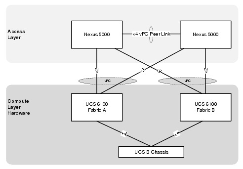
End Host Mode
End host mode allows the fabric interconnect to act as an end host to the network, representing all server (hosts) connected to it using vNICs. This connection is defined by pinning (dynamically or hard pinned) vNICs to uplink ports, which provides redundancy toward the network and presents the uplink ports as server ports to the rest of the fabric.
When in end-host mode, the fabric interconnect does not run STP and avoids loops by preventing uplink ports from forwarding traffic to each other and by denying egress server traffic on more than one uplink port at a time. End host mode is the default Ethernet switching mode, and it should be used if Layer 2 switching is used for upstream aggregation.
Figure 2-21 End Host Mode in UCSM
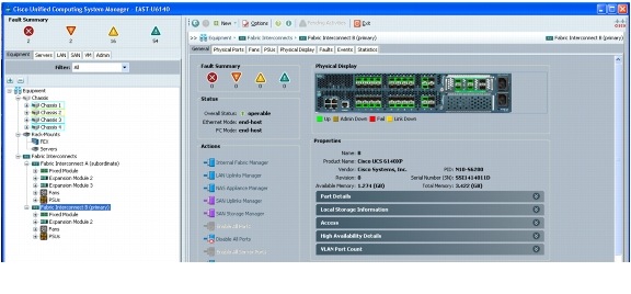
M81KR vNIC Allocation
The UCS M81KR adapter is unique for its ability to create multiple vNICs. In Cisco VMDC 2.1 10 VNICs are presented to ESXi.
The vNIC allocation is shown in Figure 2-22.
Figure 2-22 vNICs in UCSM
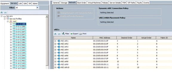
Virtual Access Layer (Nexus 1000v)
The Nexus 1000v Distributed Virtual Switch (DVS) comprises two parts: the Virtual Supervisor Modules (VSM) and Virtual Ethernet Modules (VEM).
The VSM is used to configure, manage, monitor, and diagnose issues for the Cisco Nexus 1000v Series system (VSM and all controlled VEMs). In Cisco VMDC 2.1, the Nexus 1010 appliance hosts the VSM.
The Nexus 1000v VEM is a software component that runs inside each hypervisor (ESXi host). It enables advanced networking and security features, switches between directly attached virtual machines, and provides uplink capabilities to the rest of the network.
In Cisco VMDC 2.1, the VSM connects to each VEM over Layer 2.
Figure 2-23 depicts the Nexus 1000v and Nexus 1010 deployment within the Cisco VMDC 2.1 solution.
Figure 2-23 Nexus 1000v and Nexus 1010 Deployment in the Cisco VMDC 2.1
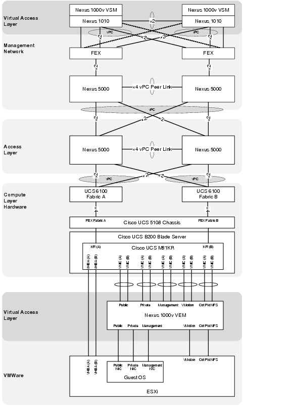
Nexus 1010 Virtual Service Appliance
In Cisco VMDC 2.1, the Nexus 1000v VSM is hosted on the Nexus 1010 platform. The Nexus 1010 is deployed using Option 3 as discussed in the following URL:
http://www.cisco.com/en/US/prod/collateral/switches/ps9441/ps9902/white_paper_c07-603623.html
The chosen deployment scenario uses the two lights-out management (LOM) interfaces for management traffic, and the four interfaces on the PCI card carry control, packet, and data traffic. This option is ideal for deploying additional virtual service blades, such as a Network Analysis Module (NAM).
In this configuration, the two management interfaces connect to two separate upstream switches for redundancy. In addition, the four ports used for control, packet, and data traffic should be divided between two upstream switches for redundancy. Since control traffic is minimal, most of the bandwidth from the four Gigabit Ethernet interfaces is used for NAM traffic.
The VMI management network Nexus 5000 uses the FEX straight-through configuration as shown in Figure 2-24, which provides support for Host Port channels needed by the Nexus 1010.
Figure 2-24 Cisco VMDC 2.1 Management Network Connections to the Virtual and Physical Access Layers
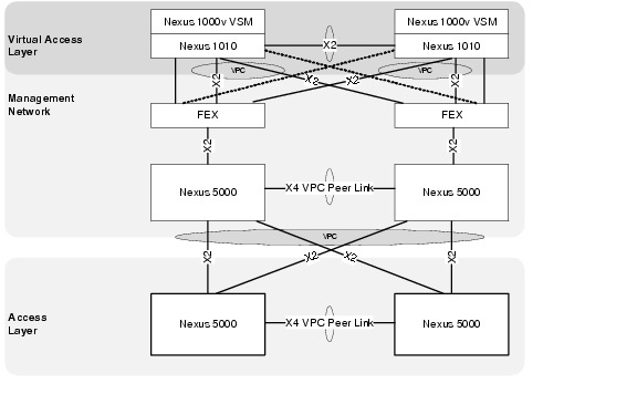
presents the Cisco VMDC 2.1 management Nexus 5000 configurations for the FEX and interfaces attached to the Nexus 1010 appliance.
Example 2-35 Example Nexus 5000 Configurations for FEX to Nexus 1010 Connections (Management Nexus 5000 A)
vlan 32
name DCPOD_2.1_DEVICE_MGMT
vlan 33
name DCPOD_2.1_MGMT_VLAN
vlan 193
name EAST-N1KV-CTRL/PKT
vlan 300
name EAST-N1010-CTRL/PAK
!
interface port-channel1001
description EAST-N1010-1-ctrl-pkt
switchport mode trunk
vpc 1001
switchport trunk allowed vlan 33,193,300
spanning-tree port type edge trunk
!
interface port-channel1002
description EAST-N1010-2-ctrl-pkt
switchport mode trunk
vpc 1002
switchport trunk allowed vlan 33,193,300
spanning-tree port type edge trunk
!
interface Ethernet1/33
fex associate 100
switchport mode fex-fabric
!
interface Ethernet1/34
fex associate 100
switchport mode fex-fabric
!
interface Ethernet100/1/1
description EAST-N1010-1-mgmt
switchport mode trunk
switchport trunk allowed vlan 32
!
interface Ethernet100/1/2
description EAST-N1010-1-ctrl-pkt
switchport mode trunk
switchport trunk allowed vlan 33,193,300
channel-group 1001 mode active
!
interface Ethernet100/1/3
description EAST-N1010-1-ctrl-pkt
switchport mode trunk
switchport trunk allowed vlan 33,193,300
channel-group 1001 mode active
!
interface Ethernet100/1/4
description EAST-N1010-2-mgmt
switchport mode trunk
switchport trunk allowed vlan 32
!
interface Ethernet100/1/5
description EAST-N1010-2-ctrl-pkt
switchport mode trunk
switchport trunk allowed vlan 33,193,300
channel-group 1002 mode active
!
interface Ethernet100/1/6
description EAST-N1010-2-ctrl-pkt
switchport mode trunk
switchport trunk allowed vlan 33,193,300
channel-group 1002 mode active
Example 2-36 Example Nexus 5000 Configurations for FEX to Nexus 1010 Connections (Management Nexus 5000 B)
vlan 32
name DCPOD_2.1_DEVICE_MGMT
vlan 33
name DCPOD_2.1_MGMT_VLAN
vlan 193
name EAST-N1KV-CTRL/PKT
vlan 300
name EAST-N1010-CTRL/PAK
!
interface port-channel1001
description EAST-N1010-1-ctrl-pkt
switchport mode trunk
vpc 1001
switchport trunk allowed vlan 33,193,300
spanning-tree port type edge trunk
!
interface port-channel1002
description EAST-N1010-2-ctrl-pkt
switchport mode trunk
vpc 1002
switchport trunk allowed vlan 33,193,300
spanning-tree port type edge trunk
!
interface Ethernet1/33
fex associate 100
switchport mode fex-fabric
!
interface Ethernet1/34
fex associate 100
switchport mode fex-fabric
!
interface Ethernet100/1/1
description EAST-N1010-1-mgmt
switchport mode trunk
switchport trunk allowed vlan 32
!
interface Ethernet100/1/2
description EAST-N1010-1-ctrl-pkt
switchport mode trunk
switchport trunk allowed vlan 33,193,300
channel-group 1001 mode active
!
interface Ethernet100/1/3
description EAST-N1010-1-ctrl-pkt
switchport mode trunk
switchport trunk allowed vlan 33,193,300
channel-group 1001 mode active
!
interface Ethernet100/1/4
description EAST-N1010-2-mgmt
switchport mode trunk
switchport trunk allowed vlan 32
!
interface Ethernet100/1/5
description EAST-N1010-2-ctrl-pkt
switchport mode trunk
switchport trunk allowed vlan 33,193,300
channel-group 1002 mode active
!
interface Ethernet100/1/6
description EAST-N1010-2-ctrl-pkt
switchport mode trunk
switchport trunk allowed vlan 33,193,300
channel-group 1002 mode active
Example 2-37 Example Nexus 1010 Configurations for FEX to Nexus 5000 Connections (Nexus 1010 configuration)
EAST-N1010-A# sho run
!
!Command: show running-config
!Time: Fri Jul 8 19:07:43 2011
!
version 4.2(1)SP1(2)
feature telnet
no feature http-server
!
banner motd #EAST Nexus 1010#
!
ip domain-lookup
ip domain-lookup
switchname EAST-N1010-A
snmp-server user admin network-admin auth md5 0x3b8f01b4aeaa4fd0c8fd99a220d527e2
priv 0x3b8f01b4aeaa4fd0c8fd99a220d527e2 localizedkey
snmp-server community public group network-operator
!
vrf context management
ip route 0.0.0.0/0 10.0.32.1
vlan 1,32,300
port-channel load-balance ethernet source-mac
port-profile default max-ports 32
!
vdc EAST-N1010-A id 1
limit-resource vlan minimum 16 maximum 2049
limit-resource monitor-session minimum 0 maximum 2
limit-resource vrf minimum 16 maximum 8192
limit-resource port-channel minimum 0 maximum 768
limit-resource u4route-mem minimum 32 maximum 32
limit-resource u6route-mem minimum 16 maximum 16
limit-resource m4route-mem minimum 58 maximum 58
limit-resource m6route-mem minimum 8 maximum 8
network-uplink type 3
virtual-service-blade EAST-N1000V-VSM
virtual-service-blade-type name VSM-1.1
interface control vlan 193
interface packet vlan 193
ramsize 2048
disksize 4
numcpu 1
cookie 145749956
no shutdown primary
no shutdown secondary
!
interface mgmt0
ip address 10.0.32.110/24
!
interface control0
line console
boot kickstart bootflash:/nexus-1010-kickstart-mz.4.2.1.SP1.2.bin
boot system bootflash:/nexus-1010-mz.4.2.1.SP1.2.bin
boot kickstart bootflash:/nexus-1010-kickstart-mz.4.2.1.SP1.2.bin
boot system bootflash:/nexus-1010-mz.4.2.1.SP1.2.bin
svs-domain
domain id 300
control vlan 300
management vlan 32
svs mode L2
vnm-policy-agent
registration-ip 0.0.0.0
shared-secret **********
log-level info
logging server 172.18.177.178 7 facility local4
logging timestamp milliseconds
logging monitor 7
logging level local4 6
VSM High Availability
Not all virtual services blades are active on the active Cisco Nexus 1010. As long as the active and standby Cisco Nexus 1010 appliances are connected, access through a serial connection is maintained to any virtual service. When one Cisco Nexus 1010 fails, the remaining Cisco Nexus 1010 becomes active and all virtual services in the standby state on that Cisco Nexus 1010 become active on their own.
For more information about VSM high availability, see the Cisco Nexus 1000v High Availability and Redundancy Configuration Guide.
Example 2-38 Nexus 1000v VSM High Availability
EAST-N1000V# sho system redundancy status
Redundancy role
---------------
administrative: primary
operational: primary
Redundancy mode
---------------
administrative: HA
operational: HA
This supervisor (sup-1)
-----------------------
Redundancy state: Active
Supervisor state: Active
Internal state: Active with HA standby
Other supervisor (sup-2)
------------------------
Redundancy state: Standby
Supervisor state: HA standby
Internal state: HA standby
EAST-N1000V#
Nexus 1000v Uplink Implementation
As mentioned in M81KR vNIC Allocation. the M81KR adapter presents 10 vNICS to the ESXi host and ultimately to the Nexus 1000v. The port-channel uplinks are implemented so each carries a specific type of traffic. The traffic types are broken down according to function as listed below:
•![]() User Application Data (Oracle, VPN, HTTP, FTP, etc.)
User Application Data (Oracle, VPN, HTTP, FTP, etc.)
•![]() Infrastructure Application Data (NFS, CIFS, Clustering, etc.)
Infrastructure Application Data (NFS, CIFS, Clustering, etc.)
•![]() Cisco Unified Computing and VMware ESXi Host Management (KVM, VPXA, etc.)
Cisco Unified Computing and VMware ESXi Host Management (KVM, VPXA, etc.)
•![]() VMware Vmotion
VMware Vmotion
•![]() Cisco Nexus 1000v (Control and Packet Traffic between VSM and VEMs)
Cisco Nexus 1000v (Control and Packet Traffic between VSM and VEMs)
The uplinks as defined in VMWare are shown in Figure 2-25.
Figure 2-25 VMWare Uplinks
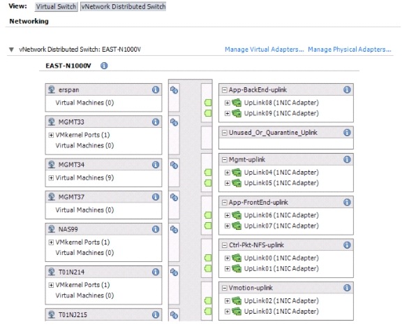
The uplinks as defined on the Nexus 1000v are shown in Example 2-39.
Example 2-39 Nexus 1000v Uplink Port Profiles
EAST-N1000V# show port-profile brief | inc uplink
----------------------------------------------------------
Port Profile Conf Eval Assigned Child
Profile State Items Items Intfs Profs
----------------------------------------------------------
App-BackEnd-uplink 1 5 5 78 0
App-FrontEnd-uplink 1 4 4 78 0
Ctrl-Pkt-NFS-uplink 1 6 6 78 0
Mgmt-uplink 1 4 4 78 0
Vmotion-uplink 1 5 5 78 0
The Nexus 5000 access layer switches are implemented using vPC which allows the Nexus 1000v to use all the available links. The uplinks on the Nexus 1000v are implemented as standard PortChannels. A standard PortChannel on the Cisco Nexus 1000V Series behaves like an EtherChannel on other Cisco switches and supports LACP. Standard PortChannels require that all uplinks in the PortChannel be in the same EtherChannel on the upstream switches.
Example 2-40 Nexus 1000v Uplink Port Channel Configuration
! PORT PROFILES
!
port-profile type ethernet App-BackEnd-uplink
vmware port-group
port-binding static
switchport mode trunk
switchport trunk allowed vlan 214-215,614-615
channel-group auto mode on mac-pinning
no shutdown
state enabled
!
port-profile type ethernet App-FrontEnd-uplink
vmware port-group
port-binding static
switchport mode trunk
switchport trunk allowed vlan 211-213,611-613
channel-group auto mode on mac-pinning
no shutdown
state enabled
!
port-profile type ethernet Ctrl-Pkt-NFS-uplink
vmware port-group
port-binding static
switchport mode trunk
switchport trunk allowed vlan 99,193-194
channel-group auto mode on mac-pinning
no shutdown
system vlan 193
state enabled
!
port-profile type ethernet Mgmt-uplink
vmware port-group
port-binding static
switchport mode trunk
switchport trunk allowed vlan 32-48,52,56,60
channel-group auto mode on mac-pinning
no shutdown
system vlan 33-34
state enabled
!
port-profile type ethernet Vmotion-uplink
vmware port-group
port-binding static
switchport mode trunk
switchport trunk allowed vlan 50
channel-group auto mode on mac-pinning
no shutdown
state enabled
!
! PORT-CHANNEL INTERFACES
!
interface port-channel1
inherit port-profile Ctrl-Pkt-NFS-uplink
!
interface port-channel2
inherit port-profile Vmotion-uplink
!
interface port-channel3
inherit port-profile Mgmt-uplink
!
interface port-channel4
inherit port-profile App-FrontEnd-uplink
!
interface port-channel5
inherit port-profile App-BackEnd-uplink
!
! ETHERNET INTERFACES
!
interface Ethernet3/1
inherit port-profile Ctrl-Pkt-NFS-uplink
no shutdown
!
interface Ethernet3/2
inherit port-profile Ctrl-Pkt-NFS-uplink
no shutdown
!
interface Ethernet3/3
inherit port-profile Vmotion-uplink
no shutdown
!
interface Ethernet3/4
inherit port-profile Vmotion-uplink
no shutdown
!
interface Ethernet3/5
inherit port-profile Mgmt-uplink
no shutdown
!
interface Ethernet3/6
inherit port-profile Mgmt-uplink
no shutdown
!
interface Ethernet3/7
inherit port-profile App-FrontEnd-uplink
no shutdown
!
interface Ethernet3/8
inherit port-profile App-FrontEnd-uplink
no shutdown
!
interface Ethernet3/9
inherit port-profile App-BackEnd-uplink
no shutdown
!
interface Ethernet3/10
inherit port-profile App-BackEnd-uplink
no shutdown
MAC Pinning
The default hashing algorithm used by the Cisco Nexus 1000V Series is source MAC address hashing (a source-based hash). Source-based hashing algorithms help ensure that a MAC address is transmitted down only a single link in the PortChannel, regardless of the number of links in a PortChannel.
With source-based hashing, a MAC address can move between interfaces under the following conditions:
•![]() The virtual machine moves to a new VMware ESX or ESXi host (VMware VMotion, VMware High Availability, etc.)
The virtual machine moves to a new VMware ESX or ESXi host (VMware VMotion, VMware High Availability, etc.)
•![]() A link fails, causing recalculation of the hashing
A link fails, causing recalculation of the hashing
Static pinning allows pinning of the virtual ports behind a VEM to a particular subgroup within the channel. Instead of allowing round robin dynamic assignment between the subgroups, you can assign (or pin) a static vEthernet interface, control VLAN, or packet VLAN to a specific port channel subgroup. With static pinning, traffic is forwarded only through the member ports in the specified subgroup.
To configure static pinning for Nexus 1000v uplink ports follow the procedure outlined below:
Choose a "sub-group id" schema and apply the ID to each Cisco Nexus 1000v Uplink Ethernet interface. In the example below the uplink ethernet interfaces directly map to UCSM vNIC interfaces.
Example 2-41 Nexus 1000v Uplink Interfaces
interface Ethernet3/1
inherit port-profile Ctrl-Pkt-NFS-uplink
no shutdown
sub-group-id 1
!
interface Ethernet3/2
inherit port-profile Ctrl-Pkt-NFS-uplink
no shutdown
sub-group-id 2
!
interface Ethernet3/3
inherit port-profile Vmotion-uplink
no shutdown
sub-group-id 3
!
interface Ethernet3/4
inherit port-profile Vmotion-uplink
no shutdown
sub-group-id 4
!
interface Ethernet3/5
inherit port-profile Mgmt-uplink
no shutdown
sub-group-id 5
!
interface Ethernet3/6
inherit port-profile Mgmt-uplink
no shutdown
sub-group-id 6
!
interface Ethernet3/7
inherit port-profile App-FrontEnd-uplink
no shutdown
sub-group-id 7
!
interface Ethernet3/8
inherit port-profile App-FrontEnd-uplink
no shutdown
sub-group-id 8
!
interface Ethernet3/9
inherit port-profile App-BackEnd-uplink
no shutdown
sub-group-id 9
!
interface Ethernet3/10
inherit port-profile App-BackEnd-uplink
no shutdown
sub-group-id 10
Configure the Cisco Nexus "Uplink" Port-profile to honor the "vethernet" port-profile to Uplink Ethernet interface assignment, when creating the Port-channel interfaces that bind the Uplink Ethernet interfaces (channel-group auto mode sub-group manual command).
Example 2-42 Nexus 1000v Uplink Port Profiles
port-profile type ethernet App-BackEnd-uplink
vmware port-group
port-binding static
switchport mode trunk
switchport trunk allowed vlan 214-215,614-615
channel-group auto mode on sub-group manual
no shutdown
state enabled
!
port-profile type ethernet App-FrontEnd-uplink
vmware port-group
port-binding static
switchport mode trunk
switchport trunk allowed vlan 211-213,611-613
channel-group auto mode on mac-pinning
no shutdown
state enabled
!
port-profile type ethernet Ctrl-Pkt-NFS-uplink
vmware port-group
port-binding static
switchport mode trunk
switchport trunk allowed vlan 99,193-194
channel-group auto mode on mac-pinning
no shutdown
system vlan 193
state enabled
!
port-profile type ethernet Mgmt-uplink
vmware port-group
port-binding static
switchport mode trunk
switchport trunk allowed vlan 32-48,52,56,60
channel-group auto mode on sub-group manual
no shutdown
system vlan 33-34
state enabled
!
port-profile type ethernet Vmotion-uplink
vmware port-group
port-binding static
switchport mode trunk
switchport trunk allowed vlan 50
channel-group auto mode on sub-group manual
no shutdown
state enabled
Assign the Cisco Nexus 1000v "vEthernet" port-profile to the correct "sub-group-id #" by using the pinning id # command. VEthernet interfaces are present as VMware ESX port-groups that virtual machine interfaces can be assigned or attached to.
Example 2-43 Nexus 1000v vEthernet Port Profiles
port-profile type vethernet MGMT34
vmware port-group
switchport mode access
switchport access vlan 34
pinning id 6
service-policy type qos input mgmt
no shutdown
max-ports 1024
description Management Network - EAST Spirent Virtual Machines
state enabled
!
port-profile type vethernet Vmotion
vmware port-group
switchport mode access
switchport access vlan 50
pinning id 3
no shutdown
system vlan 50
max-ports 64
state enabled
Virtual Access Deployment Guidelines
Layer 2 Configuration
•![]() Set MAC address aging time consistent to aggregation layer Nexus 7000 and Nexus 5000. The Nexus 7000 default aging time is 1800 seconds, and the Nexus 1000v default aging time is 300 seconds.
Set MAC address aging time consistent to aggregation layer Nexus 7000 and Nexus 5000. The Nexus 7000 default aging time is 1800 seconds, and the Nexus 1000v default aging time is 300 seconds.
•![]() Redundant VSMs should be created on the Cisco Nexus 1010 pair with the Cisco Nexus 1000V Series software image.
Redundant VSMs should be created on the Cisco Nexus 1010 pair with the Cisco Nexus 1000V Series software image.
Storage Layer
Cisco VMDC 2.1 supports storage area network (SAN) or network-attached storage (NAS) storage options depending on the overall datacenter requirements. The following sections describe how each storage type was implemented and shows VM Datastores in use on each platform.
SAN
A SAN is a dedicated storage network that provides access to consolidated, block level storage. SANs primarily are used to make storage devices (such as disk arrays, tape libraries, and optical jukeboxes) accessible to servers so that the devices appear as locally attached to the operating system.
Cisco VMDC 2.1 utilizes a dual fabric, core-edge SAN design. The design provides redundancy at key failure points to ensure reliable end-to-end connectivity for both the hosts and storage array.
Figure 2-26 SAN dual fabric implementation
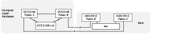
To ensure data separation, scalability, and future expansion, as well as high availability and redundancy at key points of failure, the following software features were enabled in Cisco VMDC 2.1:
•![]() VSANs-General data separation
VSANs-General data separation
•![]() IVR - Inter-VSAN Routing (IVR)
IVR - Inter-VSAN Routing (IVR)
•![]() Zone/Zoneset-Granular data separation
Zone/Zoneset-Granular data separation
•![]() NPV/NPIV-Host end scalability
NPV/NPIV-Host end scalability
Some additional details are provided around the following implementations:
•![]() UCSM WWNN/WWPN Pools
UCSM WWNN/WWPN Pools
•![]() UCS Boot From SAN
UCS Boot From SAN
•![]() Virtual Machine Datastore
Virtual Machine Datastore
VSAN
Virtual SANs (VSANs) improve storage area network (SAN) scalability, availability, and security by allowing multiple Fibre Channel SANs to share a common physical infrastructure of switches and ISLs. These benefits are derived from the separation of Fibre Channel services in each VSAN and the isolation of traffic between VSANs. Data traffic isolation between the VSANs also inherently prevents sharing of resources attached to a VSAN, such as robotic tape libraries. Unlike a typical fabric that is resized switch-by-switch, a VSAN can be resized port-by-port.
The following configurations show the Cisco VMDC 2.1 MDS 9513 VSAN configuration:
Example 2-44 MDS 9513 VSAN configuration
!9513A
vsan database
vsan 100 name "VMDC21"
vsan 500 name "EMC"
!
vsan database
vsan 100 interface fc5/1
vsan 100 interface fc5/7
vsan 500 interface fc5/13
vsan 500 interface fc5/14
vsan 100 interface fc6/1
vsan 100 interface fc6/7
vsan 500 interface fc6/13
vsan 500 interface fc6/14
!
!9513B
vsan database
vsan 101 name "VMDC21"
vsan 501 name "EMC"
vsan database
vsan 101 interface fc5/1
vsan 101 interface fc5/7
vsan 501 interface fc5/13
vsan 501 interface fc5/14
vsan 101 interface fc6/1
vsan 101 interface fc6/7
vsan 501 interface fc6/13
vsan 501 interface fc6/14
Inter VSAN Routing (IVR)
Cisco VMDC 2.1 uses IVR to route between the VSAN defined for the datacenter and the VSAN assigned to the EMC storage array. The following features were configured on the MDS 9513 SAN switches:
•![]() IVR Distribution. The IVR feature uses the Cisco Fabric Services (CFS) infrastructure to enable efficient configuration management and to provide a single point of configuration for the entire fabric in the VSAN.
IVR Distribution. The IVR feature uses the Cisco Fabric Services (CFS) infrastructure to enable efficient configuration management and to provide a single point of configuration for the entire fabric in the VSAN.
•![]() IVR Network Address Translation (NAT). This IVR feature can be enabled to allow non-unique domain IDs; however, without NAT, IVR requires unique domain IDs for all switches in the fabric. IVR NAT simplifies the deployment of IVR in an existing fabric where non-unique domain IDs might be present.
IVR Network Address Translation (NAT). This IVR feature can be enabled to allow non-unique domain IDs; however, without NAT, IVR requires unique domain IDs for all switches in the fabric. IVR NAT simplifies the deployment of IVR in an existing fabric where non-unique domain IDs might be present.
•![]() IVR Auto Topology Mode. This IVR feature automatically builds the IVR VSAN topology and maintains the topology database when fabric re-configurations occur. IVR auto topology mode also distributes the IVR VSAN topology to IVR-enabled switches using CFS.
IVR Auto Topology Mode. This IVR feature automatically builds the IVR VSAN topology and maintains the topology database when fabric re-configurations occur. IVR auto topology mode also distributes the IVR VSAN topology to IVR-enabled switches using CFS.
Figure 2-27 IVR/VSAN Implementation
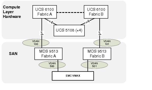
The MDS 9513 configurations below show the following IVR feature configurations for a single blade server in the Cisco VMDC 2.1 construct:
•![]() IVR Distribution
IVR Distribution
•![]() IVR NAT
IVR NAT
•![]() IVR Auto Topology
IVR Auto Topology
•![]() Active Zonesets
Active Zonesets
Example 2-45 MDS 9513 IVR Configuration
!9513A
!
feature ivr
ivr nat
ivr distribute
ivr vsan-topology auto
zone mode enhanced vsan 100
zone mode enhanced vsan 500
!
!Example for a single blade server
!
device-alias database
device-alias name EMC-7fA pwwn 50:00:09:72:08:1f:3d:58
device-alias name EMC-8fA pwwn 50:00:09:72:08:1f:3d:5c
device-alias name EMC-9fA pwwn 50:00:09:72:08:1f:3d:60
device-alias name EMC-10fA pwwn 50:00:09:72:08:1f:3d:64
device-alias name EAST-C1B1 pwwn 20:00:00:25:b5:00:01:14
!
fcdomain distribute
fcdomain fcid database
vsan 100 wwn 20:00:00:25:b5:00:01:14 fcid 0x010031 dynamic
! [EAST-C1B1]
vsan 500 wwn 50:00:09:72:08:1f:3d:58 fcid 0x610000 dynamic
! [EMC-7fA]
vsan 500 wwn 50:00:09:72:08:1f:3d:5c fcid 0x610001 dynamic
! [EMC-8fA]
vsan 500 wwn 50:00:09:72:08:1f:3d:60 fcid 0x610003 dynamic
! [EMC-9fA]
vsan 500 wwn 50:00:09:72:08:1f:3d:64 fcid 0x610002 dynamic
! [EMC-10fA]
!
!Active Zone Database Section for vsan 100
zone name IVRZ_EAST-C1B1_to_VMAX1999 vsan 100
member pwwn 20:00:00:25:b5:00:01:14
! [EAST-C1B1]
member pwwn 50:00:09:72:08:1f:3d:58
! [EMC-7fA]
member pwwn 50:00:09:72:08:1f:3d:5c
! [EMC-8fA]
member pwwn 50:00:09:72:08:1f:3d:60
! [EMC-9fA]
member pwwn 50:00:09:72:08:1f:3d:64
! [EMC-10fA]
!
zoneset name nozoneset vsan 100
member IVRZ_EAST-C1B1_to_VMAX1999
!
ivr zone name EAST-C1B1_to_VMAX1999
member pwwn 20:00:00:25:b5:00:01:14 vsan 100
! [EAST-C1B1]
member pwwn 50:00:09:72:08:1f:3d:64 vsan 500
! [EMC-10fA]
member pwwn 50:00:09:72:08:1f:3d:58 vsan 500
! [EMC-7fA]
member pwwn 50:00:09:72:08:1f:3d:5c vsan 500
! [EMC-8fA]
member pwwn 50:00:09:72:08:1f:3d:60 vsan 500
! [EMC-9fA]
!
ivr zoneset name dcpod_fab_a_ivr
member EAST-C1B1_to_VMAX1999
!
! show command output
SAN-M9513-A# sho ivr
Inter-VSAN Routing is enabled
Inter-VSAN enabled switches
---------------------------
AFID VSAN DOMAIN CAPABILITY SWITCH WWN
-------------------------------------------------------------------
1 1 0xa4(164) 0000001f 20:00:00:0d:ec:3b:b6:40 *
1 100 0x 1( 1) 0000001f 20:00:00:0d:ec:3b:b6:40 *
1 200 0x 2( 2) 0000001f 20:00:00:0d:ec:3b:b6:40 *
1 500 0x61( 97) 0000001f 20:00:00:0d:ec:3b:b6:40 *
Total: 4 IVR-enabled VSAN-Domain pairs
Inter-VSAN topology status
--------------------------
Current Status: Inter-VSAN topology is ACTIVE, AUTO Mode
Last activation time: Fri Dec 10 21:40:35 2010
Inter-VSAN zoneset status
-------------------------
name : dcpod_fab_a_ivr
state : activation success
last activate time : Fri Feb 11 19:49:04 2011
Fabric distribution status
-----------------------
fabric distribution enabled
Last Action Time Stamp : Fri Feb 11 19:48:48 2011
Last Action : Commit
Last Action Result : Success
Last Action Failure Reason : none
Inter-VSAN NAT mode status
--------------------------
FCID-NAT is enabled
Last activation time : Mon Dec 6 16:43:40 2010
AAM mode status
--------------------------
AAM is disabled
License status
-----------------
IVR is running based on the following license(s)
ENTERPRISE_PKG
Sharing of tcam space across xE ports disabled
SAN-M9513-A# show ivr zoneset active
zone name EAST-C1B1_to_VMAX1999
* pwwn 20:00:00:25:b5:00:01:14 vsan 100 autonomous-fabric-id 1
[EAST-C1B1]
pwwn 50:00:09:72:08:1f:3d:64 vsan 500 autonomous-fabric-id 1
[EMC-10fA]
* pwwn 50:00:09:72:08:1f:3d:58 vsan 500 autonomous-fabric-id 1
[EMC-7fA]
pwwn 50:00:09:72:08:1f:3d:5c vsan 500 autonomous-fabric-id 1
[EMC-8fA]
* pwwn 50:00:09:72:08:1f:3d:60 vsan 500 autonomous-fabric-id 1
[EMC-9fA]
!
!9513B
!
feature ivr
ivr nat
ivr distribute
ivr vsan-topology auto
zone mode enhanced vsan 101
zone mode enhanced vsan 501
!
!Example for a single blade server
!
device-alias database
device-alias name EMC-7fB pwwn 50:00:09:72:08:1f:3d:59
device-alias name EMC-8fB pwwn 50:00:09:72:08:1f:3d:5d
device-alias name EMC-9fB pwwn 50:00:09:72:08:1f:3d:61
device-alias name EMC-10fB pwwn 50:00:09:72:08:1f:3d:65
device-alias name EAST-C1B1 pwwn 20:00:00:25:b5:00:02:14
!
fcdomain distribute
fcdomain fcid database
vsan 501 wwn 50:00:09:72:08:1f:3d:59 fcid 0x1c0000 dynamic
! [EMC-7fB]
vsan 501 wwn 50:00:09:72:08:1f:3d:61 fcid 0x1c0001 dynamic
! [EMC-9fB]
vsan 501 wwn 50:00:09:72:08:1f:3d:5d fcid 0x1c0002 dynamic
! [EMC-8fB]
vsan 501 wwn 50:00:09:72:08:1f:3d:65 fcid 0x1c0003 dynamic
! [EMC-10fB]
vsan 101 wwn 20:00:00:25:b5:00:02:14 fcid 0x1f0030 dynamic
! [EAST-C1B1]
!
!Active Zone Database Section for vsan 101
zone name IVRZ_EAST-C1B1_to_VMAX1999 vsan 101
member pwwn 20:00:00:25:b5:00:02:14
! [EAST-C1B1]
member pwwn 50:00:09:72:08:1f:3d:59
! [EMC-7fB]
member pwwn 50:00:09:72:08:1f:3d:5d
! [EMC-8fB]
member pwwn 50:00:09:72:08:1f:3d:61
! [EMC-9fB]
member pwwn 50:00:09:72:08:1f:3d:65
! [EMC-10fB]
!
zoneset name nozoneset vsan 101
member IVRZ_EAST-C1B1_to_VMAX1999
!
ivr zone name EAST-C1B1_to_VMAX1999
member pwwn 50:00:09:72:08:1f:3d:65 vsan 501
! [EMC-10fB]
member pwwn 50:00:09:72:08:1f:3d:59 vsan 501
! [EMC-7fB]
member pwwn 50:00:09:72:08:1f:3d:5d vsan 501
! [EMC-8fB]
member pwwn 50:00:09:72:08:1f:3d:61 vsan 501
! [EMC-9fB]
member pwwn 20:00:00:25:b5:00:02:14 vsan 101
! [EAST-C1B1]
!
ivr zoneset name dcpod_fab_b_ivr
member EAST-C1B1_to_VMAX1999
!
! show command output
!
SAN-M9513-B# sho ivr
Inter-VSAN Routing is enabled
Inter-VSAN enabled switches
---------------------------
AFID VSAN DOMAIN CAPABILITY SWITCH WWN
-------------------------------------------------------------------
1 1 0x d( 13) 0000001f 20:00:00:0d:ec:2d:0e:40 *
1 101 0x1f( 31) 0000001f 20:00:00:0d:ec:2d:0e:40 *
1 201 0x21( 33) 0000001f 20:00:00:0d:ec:2d:0e:40 *
1 501 0x1c( 28) 0000001f 20:00:00:0d:ec:2d:0e:40 *
Total: 4 IVR-enabled VSAN-Domain pairs
Inter-VSAN topology status
--------------------------
Current Status: Inter-VSAN topology is ACTIVE, AUTO Mode
Last activation time: Tue Dec 14 17:02:00 2010
Inter-VSAN zoneset status
-------------------------
name : dcpod_fab_b_ivr
state : activation success
last activate time : Fri Feb 11 20:01:12 2011
Fabric distribution status
-----------------------
fabric distribution enabled
Last Action Time Stamp : Fri Feb 11 20:00:55 2011
Last Action : Commit
Last Action Result : Success
Last Action Failure Reason : none
Inter-VSAN NAT mode status
--------------------------
FCID-NAT is enabled
Last activation time : Tue Dec 14 17:02:00 2010
AAM mode status
--------------------------
AAM is disabled
License status
-----------------
IVR is running based on the following license(s)
ENTERPRISE_PKG
Sharing of tcam space across xE ports disabled
SAN-M9513-B# sho ivr zoneset active
zone name EAST-C1B1_to_VMAX1999
pwwn 50:00:09:72:08:1f:3d:65 vsan 501 autonomous-fabric-id 1
[EMC-10fB]
* pwwn 50:00:09:72:08:1f:3d:59 vsan 501 autonomous-fabric-id 1
[EMC-7fB]
pwwn 50:00:09:72:08:1f:3d:5d vsan 501 autonomous-fabric-id 1
[EMC-8fB]
* pwwn 50:00:09:72:08:1f:3d:61 vsan 501 autonomous-fabric-id 1
[EMC-9fB]
* pwwn 20:00:00:25:b5:00:02:14 vsan 101 autonomous-fabric-id 1
The configuration can also be seen through either the Fabric Manager or Datacenter Network Manager applications.
Figure 2-28 Fabric Manager (FM) IVR Fabric A implementation
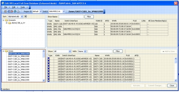
Figure 2-29 Fabric Manager (FM) IVR Fabric B implementation

NPIV/NPV
NPIV allows a Fibre Channel host connection or N-Port to be assigned multiple N-Port IDs or Fibre Channel IDs (FCIDs) over a single link. All FCIDs assigned are managed on a Fibre Channel fabric as unique entities on the same physical host. Different applications can be used in conjunction with NPIV. In a virtual machine environment where many host operating systems or applications are running on a physical host, each virtual machine can now be managed independently from zoning, aliasing, and security perspectives. In a Cisco VMDC 2.1 which uses the Cisco MDS 9513environment, each host connection can log in as a single virtual SAN (VSAN).
Example 2-46 MDS 9513 NPIV Configuration
!9513A
SAN-M9513-A# sho run | inc npiv
feature npiv
!
SAN-M9513-A# show npiv status
NPIV is enabled
!
!9513B
SAN-M9513-B# sho run | inc npiv
feature npiv
!
SAN-M9513-B# show npiv status
NPIV is enabled
An extension to NPIV, the N-Port Virtualizer (NPV) feature allows the UCS 6140 Fabric Interconnect device to behave as an NPIV-based host bus adapter (HBA) to the core Fibre Channel director MDS 9513. The device aggregates the locally connected host ports or N-Ports into one or more uplinks (pseudo-interswitch links) to the core switches. The only requirement of the core director is that it supports the NPIV feature.
Example 2-47 UCS 6140 NPV Configuration
!6140A
EAST-U6140-A(nxos)# show run | in npv|npiv
feature npv
npv enable
feature npiv
!
EAST-U6140-A(nxos)# show npv status
npiv is enabled
disruptive load balancing is disabled
External Interfaces:
====================
Interface: fc2/1, VSAN: 100, FCID: 0x010000, State: Up
Interface: fc2/3, VSAN: 100, FCID: 0x010001, State: Up
Interface: fc3/1, VSAN: 100, FCID: 0x010002, State: Up
Interface: fc3/3, VSAN: 100, FCID: 0x010003, State: Up
Number of External Interfaces: 4
Server Interfaces:
==================
Interface: vfc1287, VSAN: 100, State: Up
Interface: vfc1297, VSAN: 100, State: Up
Interface: vfc1307, VSAN: 100, State: Up
Interface: vfc1317, VSAN: 100, State: Up
Interface: vfc1327, VSAN: 100, State: Up
Interface: vfc1337, VSAN: 100, State: Up
Interface: vfc1347, VSAN: 100, State: Up
Interface: vfc1367, VSAN: 100, State: Up
Interface: vfc1387, VSAN: 100, State: Up
Interface: vfc1407, VSAN: 100, State: Up
Interface: vfc1417, VSAN: 100, State: Up
Interface: vfc1427, VSAN: 100, State: Up
Interface: vfc1437, VSAN: 100, State: Up
Interface: vfc1447, VSAN: 100, State: Up
Interface: vfc1457, VSAN: 100, State: Up
Interface: vfc1467, VSAN: 100, State: Up
Interface: vfc1477, VSAN: 100, State: Up
Interface: vfc1487, VSAN: 100, State: Up
Interface: vfc1497, VSAN: 100, State: Up
Interface: vfc1507, VSAN: 100, State: Up
Interface: vfc1537, VSAN: 100, State: Up
Interface: vfc1547, VSAN: 100, State: Up
Interface: vfc1612, VSAN: 100, State: Up
Interface: vfc1636, VSAN: 100, State: Up
Interface: vfc1696, VSAN: 100, State: Up
Interface: vfc2467, VSAN: 100, State: Up
Number of Server Interfaces: 26
!6140B
EAST-U6140-B(nxos)# show run | in npv|npiv
feature npv
npv enable
feature npiv
EAST-U6140-B(nxos)# show npv status
npiv is enabled
disruptive load balancing is disabled
External Interfaces:
====================
Interface: fc2/1, VSAN: 101, FCID: 0x1f0000, State: Up
Interface: fc2/2, VSAN: 101, FCID: 0x1f0003, State: Up
Interface: fc2/3, VSAN: 101, FCID: 0x1f0001, State: Up
Interface: fc2/4, VSAN: 101, FCID: 0x1f0002, State: Up
Number of External Interfaces: 4
Server Interfaces:
==================
Interface: vfc1288, VSAN: 101, State: Up
Interface: vfc1298, VSAN: 101, State: Up
Interface: vfc1308, VSAN: 101, State: Up
Interface: vfc1318, VSAN: 101, State: Up
Interface: vfc1328, VSAN: 101, State: Up
Interface: vfc1338, VSAN: 101, State: Up
Interface: vfc1348, VSAN: 101, State: Up
Interface: vfc1368, VSAN: 101, State: Up
Interface: vfc1388, VSAN: 101, State: Up
Interface: vfc1408, VSAN: 101, State: Up
Interface: vfc1418, VSAN: 101, State: Up
Interface: vfc1428, VSAN: 101, State: Up
Interface: vfc1438, VSAN: 101, State: Up
Interface: vfc1448, VSAN: 101, State: Up
Interface: vfc1458, VSAN: 101, State: Up
Interface: vfc1468, VSAN: 101, State: Up
Interface: vfc1478, VSAN: 101, State: Up
Interface: vfc1488, VSAN: 101, State: Up
Interface: vfc1498, VSAN: 101, State: Up
Interface: vfc1508, VSAN: 101, State: Up
Interface: vfc1538, VSAN: 101, State: Up
Interface: vfc1548, VSAN: 101, State: Up
Interface: vfc1613, VSAN: 101, State: Up
Interface: vfc1637, VSAN: 101, State: Up
Interface: vfc1697, VSAN: 101, State: Up
Interface: vfc2468, VSAN: 101, State: Up
Number of Server Interfaces: 26
UCSM WWNN/WWPN Pools
UCSM allows the server administrators the option of assigning the WWNN/WWPN manually for each B200 blade server or to create a pool that will be used to dynamically assign pre-defined WWNN/WWPN addresses. The Cisco VMDC 2.1 SAN implementation utilizes dynamic WWNN/WWPN pools as illustrated in Figure 2-30.
Figure 2-30 UCSM WWNN/WWPN Pool Definition
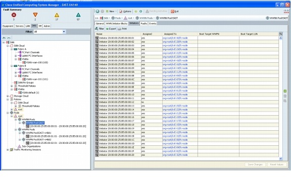
UCS Boot from SAN
In Cisco VMDC 2.1, each of the UCS B-200 blade servers is configured to boot VMWare ESXi from a small boot LUN (5GB) as the primary option.
Figure 2-31 UCS Boot Order Configuration in UCSM

In VMWare VCenter the ESXi host boot partition can be seen once the host is online.
Figure 2-32 VMware VCenter ESXi Disk Configuration
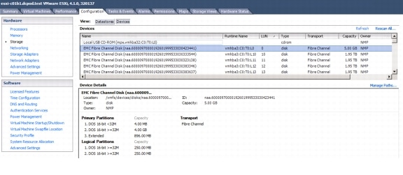
And if the configuration is further expanded the dual fabric paths can be seen in VMWare VCenter.
Figure 2-33 VMware VCenter ESXi showing SAN Fabric A and B Paths
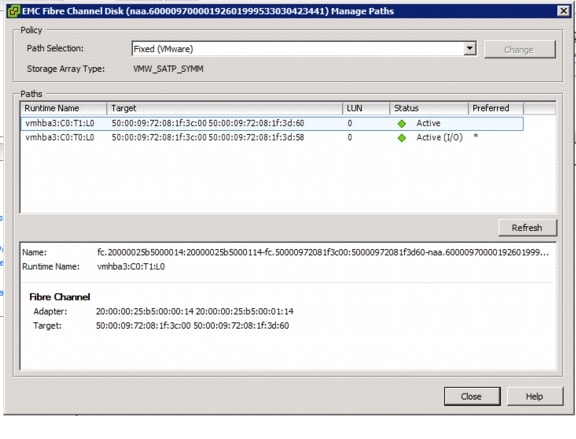
Virtual Machine Datastore Configuration
The SAN provides only block-based storage and leaves file system concerns to the client (host) side. In Cisco VMDC 2.1 the tenant vSphere virtual machine files (.vmx, .vmk, snapshots, etc.) which are stored on the SAN (Block Device) need a VMFS formatted datastore. The VMFS formatting is done through VMWare once the disk is accessible. The following diagrams illustrate a few details around the datastore configured for Tenant 1.
Figure 2-34 VMware VCenter ESXi showing Virtual Machine Datastore
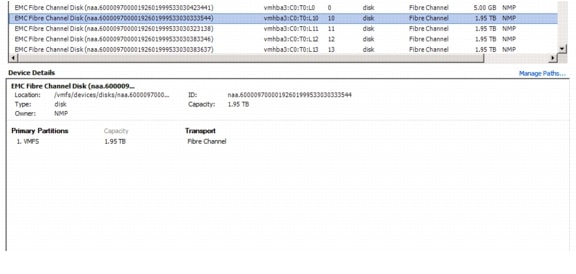
Figure 2-35 VMware VCenter Tenant 1 VM DataStore Details
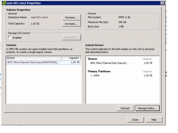
And if the configuration is further expanded the dual fabric paths can be seen in VMWare VCenter.
Figure 2-36 VMware VCenter ESXi showing 4 Paths to a VM DataStore

Cisco VMDC 2.1 also implemented the additional EMC features listed below:
•![]() Logical Device separation (EMC LUN Masking and Mapping) - LUN masking, in conjunction with SAN zoning, extends the security from the SAN to the internal storage array by creating a logical connection from the host pWWN to the LUN device through the FA ports.
Logical Device separation (EMC LUN Masking and Mapping) - LUN masking, in conjunction with SAN zoning, extends the security from the SAN to the internal storage array by creating a logical connection from the host pWWN to the LUN device through the FA ports.
•![]() Storage Thin Provisioning (EMC Virtual Provisioning) - Thin provisioning the LUNs at the storage level enables efficient use of available space on the storage array and hot expansion of the storage array by simply adding data devices to the thin pool.
Storage Thin Provisioning (EMC Virtual Provisioning) - Thin provisioning the LUNs at the storage level enables efficient use of available space on the storage array and hot expansion of the storage array by simply adding data devices to the thin pool.
NAS
NAS, in contrast to SAN, provides both storage and a file system. NAS uses file-based protocols such as NFS or SMB/CIFS where it is clear that the storage is remote, and computers request a portion of an abstract file rather than a disk block.
To ensure data separation, scalability, and future expansion, as well as high availability and redundancy at key points of failure, the following software features were enabled in Cisco VMDC 2.1:
•![]() 10GE Path Redundancy (Cisco vPC and NetApp LACP Trunking)
10GE Path Redundancy (Cisco vPC and NetApp LACP Trunking)
•![]() Virtual Filer Separation (NetApp vFiler) per Tenant
Virtual Filer Separation (NetApp vFiler) per Tenant
Some additional details are provided around the following implementations:
•![]() Virtual Machine Datastore
Virtual Machine Datastore
VLAN and Virtual Adapter Configuration
In Cisco VMDC 2.1, a backend VLAN could be used to access the NAS device. There are several implementation scenarios that could be accomplished in the Cisco VMDC 2.1 topology.
•![]() Common vFiler - This datastore can be used as a common device where all tenant VMs may be housed and booted from. Only VMWare would have access to this datastore and VLANs would not be exposed to any tenant devices.
Common vFiler - This datastore can be used as a common device where all tenant VMs may be housed and booted from. Only VMWare would have access to this datastore and VLANs would not be exposed to any tenant devices.
•![]() Per Tenant vFiler - These datastores are allocated on a per tenant basis. It can be accessed either with a separate virtual interface on VMWare used to boot VMs or present a vFiler which can be mapped directly through tenant VMs.
Per Tenant vFiler - These datastores are allocated on a per tenant basis. It can be accessed either with a separate virtual interface on VMWare used to boot VMs or present a vFiler which can be mapped directly through tenant VMs.
The NAS VLAN allocation was done as follows:
Note ![]() Throughout this document, example configurations reference the NAS VLANs used in Table 2-5.
Throughout this document, example configurations reference the NAS VLANs used in Table 2-5.
The following figures show the VMWare Virtual Adapters assigned to each of the following VLANs.
•![]() Common vFiler
Common vFiler
•![]() Per Tenant vFiler - Standard and Jumbo Frame implementations
Per Tenant vFiler - Standard and Jumbo Frame implementations
Figure 2-37 VMWare Virtual Adapter for vFiler 0 (Common vFiler)
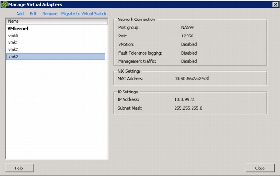
Figure 2-38 VMWare Virtual Adapter for Tenant 1 vFiler (1500 Byte Frames)
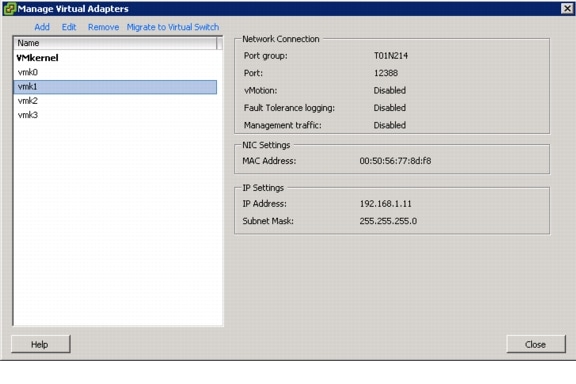
Figure 2-39 VMWare Virtual Adapter for Tenant 1 vFiler (9000 Byte Frames)
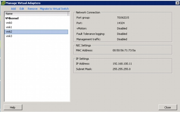
vPC to NetApp
A virtual port channel (vPC) allows links that are physically connected to two different Cisco Nexus 5000 Series devices to appear as a single port channel by a third device. The third device in the Cisco VMDC 2.1 storage context is the NetApp FAS6080. A vPC provides Layer 2 multipathing, which allows you to create redundancy and increase bisectional bandwidth by enabling multiple parallel paths between nodes and allowing load balancing traffic.
Figure 2-40 Nexus 5000 vPC implementation with NetApp FAS6080
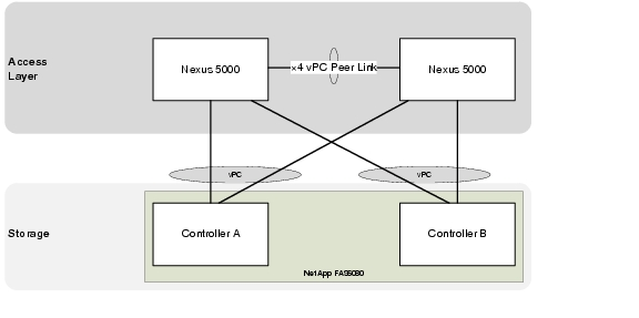
Example 2-48 Nexus 5000 vPC Configuration
! Access Layer Nexus 5000A
! Reference the peer-link configuration in the Access Layer Section
!
interface port-channel4
description vpc vmdc-netapp6080-1-7a
switchport mode trunk
vpc 4
  switchport trunk allowed vlan
14,99,214-215,224-225,234-235,244-245,254-255,264-265,274-275,284-285
spanning-tree port type edge trunk
!
interface port-channel5
description vpc vmdc-netapp6080-2-7a
switchport mode trunk
vpc 5
  switchport trunk allowed vlan
14,99,214-215,224-225,234-235,244-245,254-255,264-265,274-275,284-285
spanning-tree port type edge trunk
!
interface Ethernet1/3
description to vmdc-netapp6080-1-7b
switchport mode trunk
  switchport trunk allowed vlan
14,99,214-215,224-225,234-235,244-245,254-255,264-265,274-275,284-285
channel-group 4 mode active
!
interface Ethernet1/4
description to vmdc-netapp6080-2-7b
switchport mode trunk
  switchport trunk allowed vlan
14,99,214-215,224-225,234-235,244-245,254-255,264-265,274-275,284-285
channel-group 5 mode active
!
! Access Layer Nexus 5000B
! Reference the peer-link configuration in the Access Layer Section
!
interface port-channel4
description vpc vmdc-netapp6080-1-7a
switchport mode trunk
vpc 4
  switchport trunk allowed vlan
14,99,214-215,224-225,234-235,244-245,254-255,264-265,274-275,284-285
spanning-tree port type edge trunk
!
interface port-channel5
description vpc vmdc-netapp6080-2-7a
switchport mode trunk
vpc 5
  switchport trunk allowed vlan
14,99,214-215,224-225,234-235,244-245,254-255,264-265,274-275,284-285
spanning-tree port type edge trunk
!
interface Ethernet1/3
description to vmdc-netapp6080-1-7b
switchport mode trunk
  switchport trunk allowed vlan
14,99,214-215,224-225,234-235,244-245,254-255,264-265,274-275,284-285
channel-group 4 mode active
!
interface Ethernet1/4
description to vmdc-netapp6080-2-7b
switchport mode trunk
  switchport trunk allowed vlan
14,99,214-215,224-225,234-235,244-245,254-255,264-265,274-275,284-285
channel-group 5 mode active
The NetApp FAS6080 System Manager Configuration can be used to create interfaces and vFilers.
Figure 2-41 NetApp FAS6080 System Manager Interface Configuration
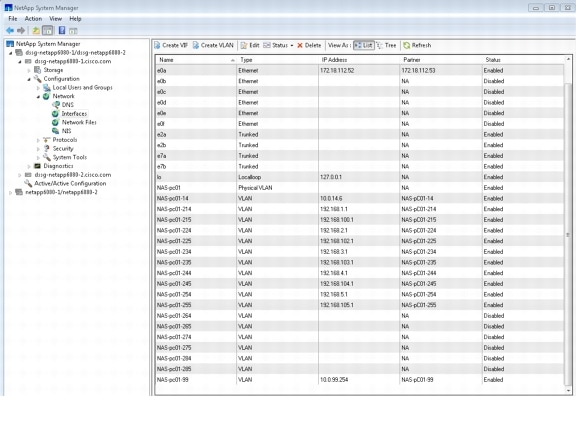
Virtual Machine Datastore Configuration
The NAS provides both storage and a file system so there is no need to format the disks. In Cisco VMDC 2.1, VMWare mapping was done via NFS.
Figure 2-42 illustrates a few details around the datastores configured for Tenant 1.
Figure 2-42 VMware VCenter ESXi NFS Datastore Mapping
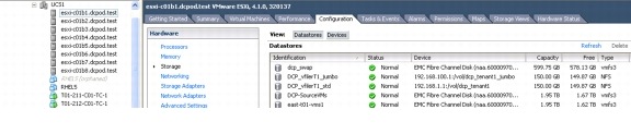
Additional Technology Implementation
The following technologies were highlighted in Cisco VMDC 2.1:
Jumbo MTU Implementation
A jumbo frame is basically anything bigger than 1522 bytes, with a common size of 9000 bytes, which is exactly six times the size of a standard Ethernet frame. With Ethernet headers, a 9k byte jumbo frame would be 9014-9022 bytes. This makes it large enough to encapsulate a standard NFS (network file system) data block of 8192 bytes, yet not large enough to exceed the 12,000 byte limit of Ethernet's error checking CRC (cyclic redundancy check) algorithm.
Large frames are commonly employed in large data transfers; in contrast, for interactive data flows, such as terminal connections, small packets are normally used. In Cisco VMDC 2.1, jumbo MTU uses targets applications such as:
•![]() Server back-to-back communication (e.g., NFS transactions)
Server back-to-back communication (e.g., NFS transactions)
•![]() Server clustering
Server clustering
•![]() High-speed data backups
High-speed data backups
Figure 2-43 shows the physical links in the Cisco VMDC 2.1 solution that were configured to carry jumbo frames.
Figure 2-43 Physical Links Carrying Jumbo Frames in VDMC 2.1
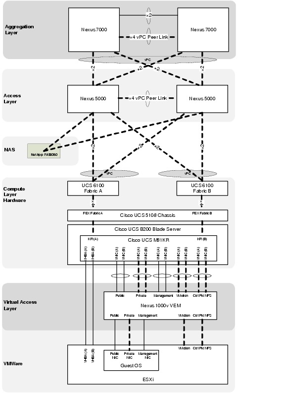
Nexus 7010
Example 2-49 Nexus 7010 Jumbo Frame Configuration on Layer 3 interfaces
system jumbomtu 9216
! Layer 3 Port-Channel Interfaces
!
interface port-channel1
description to EAST-DIST-B
mtu 9216
interface port-channel1.1
description T1U PC Subif to DIST-B
mtu 9216
encapsulation dot1q 3001
vrf member T1U
no ip redirects
ip address 10.1.28.17/30
ip ospf cost 5
ip ospf network point-to-point
ip router ospf 1 area 0.0.0.10
no shutdown
interface port-channel1.101
description T1P PC Subif to DIST-B
mtu 9216
encapsulation dot1q 3501
vrf member T1P
no ip redirects
ip address 10.1.60.17/30
ip ospf cost 5
ip ospf network point-to-point
ip router ospf 1 area 0.0.0.10
no shutdown
!
! Layer 3 VLAN Interfaces
!
interface Vlan211
no shutdown
mtu 9216
description Tenant 1 Unprotected Frontend VLAN
vrf member T1U
no ip redirects
ip address 10.1.1.251/24
ip ospf passive-interface
ip router ospf 1 area 0.0.0.10
hsrp 1
preempt delay minimum 120
priority 110
ip 10.1.1.253
!
interface Vlan611
no shutdown
mtu 9216
description Tenant 1 Protected Frontend VLAN
vrf member T1P
no ip redirects
ip address 10.1.41.251/24
ip ospf passive-interface
ip router ospf 1 area 0.0.0.10
hsrp 1
preempt delay minimum 120
priority 110
ip 10.1.41.253
Nexus 5000
You can enable the jumbo MTU for the whole switch by setting the MTU to its maximum size (9216 bytes) in the policy map for either the default (class-default) or each system class defined.
Example 2-50 shows how to configure each class to support the jumbo MTU:
Example 2-50 EAST-N5020-A System Jumbo MTU
system jumbomtu 9216
!
class-map type network-qos class-gold
match qos-group 4
class-map type network-qos class-bronze
match qos-group 2
class-map type network-qos class-silver
match qos-group 3
class-map type network-qos class-platinum
match qos-group 5
!
policy-map type network-qos system-level-qos
class type network-qos class-platinum
queue-limit 30000 bytes
mtu 9216
set cos 5
class type network-qos class-gold
queue-limit 30000 bytes
mtu 9216
set cos 4
class type network-qos class-silver
queue-limit 30000 bytes
mtu 9216
set cos 2
class type network-qos class-bronze
queue-limit 30000 bytes
mtu 9216
multicast-optimize
set cos 1
class type network-qos class-fcoe
pause no-drop
mtu 2158
class type network-qos class-default
mtu 9216
!
system qos
service-policy type network-qos system-level-qos
To verify that the jumbo MTU is enabled, enter the show interface ethernet slot/port command for an Ethernet interface that carries traffic with jumbo MTU.
Example 2-51 EAST-N5020-A Show Interface
EAST-N5020-A# sho int eth 1/1
Ethernet1/1 is up
Hardware: 1000/10000 Ethernet, address: 0005.9b21.0c88 (bia 0005.9b21.0c88)
Description: to_EAST-U6140-A_1-33
MTU 1500 bytes, BW 10000000 Kbit, DLY 10 usec,
reliability 255/255, txload 1/255, rxload 1/255
Encapsulation ARPA
Port mode is trunk
full-duplex, 10 Gb/s, media type is 10G
Beacon is turned off
Input flow-control is off, output flow-control is off
Rate mode is dedicated
Switchport monitor is off
EtherType is 0x8100
Last link flapped 6week(s) 5day(s)
Last clearing of "show interface" counters 00:37:50
30 seconds input rate 124880 bits/sec, 15610 bytes/sec, 31 packets/sec
30 seconds output rate 128064 bits/sec, 16008 bytes/sec, 133 packets/sec
Load-Interval #2: 5 minute (300 seconds)
input rate 122.71 Kbps, 7 pps; output rate 142.56 Kbps, 87 pps
RX
83244 unicast packets 188 multicast packets 8 broadcast packets
83440 input packets 22487108 bytes
1159 jumbo packets 0 storm suppression packets
0 runts 0 giants 0 CRC 0 no buffer
0 input error 0 short frame 0 overrun 0 underrun 0 ignored
0 watchdog 0 bad etype drop 0 bad proto drop 0 if down drop
0 input with dribble 0 input discard
0 Rx pause
TX
382896 unicast packets 123185 multicast packets 2309 broadcast packets
508390 output packets 89230940 bytes
0 jumbo packets
0 output errors 0 collision 0 deferred 0 late collision
0 lost carrier 0 no carrier 0 babble
0 Tx pause
0 interface resets
EAST-N5020-A# sho int eth 1/1 counters detailed
Ethernet1/1
Rx Packets: 83477
Rx Unicast Packets: 83279
Rx Multicast Packets: 190
Rx Broadcast Packets: 8
Rx Jumbo Packets: 1159
Rx Bytes: 22494983
Rx Packets from 65 to 127 bytes: 34608
Rx Packets from 128 to 255 bytes: 16909
Rx Packets from 256 to 511 bytes: 29582
Rx Packets from 512 to 1023 bytes: 710
Rx Packets from 1024 to 1518 bytes: 509
Rx Trunk Packets: 83287
Tx Packets: 508832
Tx Unicast Packets: 383019
Tx Multicast Packets: 123499
Tx Broadcast Packets: 2314
Tx Bytes: 89273805
Tx Packets from 0 to 64 bytes: 1010
Tx Packets from 65 to 127 bytes: 226616
Tx Packets from 128 to 255 bytes: 64059
Tx Packets from 256 to 511 bytes: 216621
Tx Packets from 512 to 1023 bytes: 526
Tx Trunk Packets: 508321
EAST-N5020-A#
UCS 6100 Fabric Interconnect
In the UCSM GUI, two panels organize the settings that enable Jumbo Frame Support.
On specific vNIC template, set the MTU on the vNIC (change for template):
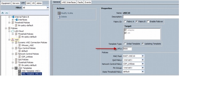
Under the QoS Service Class page of the applicable fabric, you can change the MTU for each QoS service class:

For each Class of Service (CoS) set the desired MTU byte value:
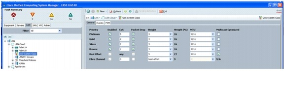
Nexus 1000v
By default, the Cisco Nexus 1000v supports 1500 byte MTU.
To enable jumbo frame support, follow these steps:
Step 1 ![]() Under the correct uplink Ethernet port-profile, add the command:
Under the correct uplink Ethernet port-profile, add the command:
mtu 9000
Example 2-52 Example show port-profile Output (N1000v Jumbo Frame configuration)
port-profile type ethernet App-BackEnd-uplink
vmware port-group
port-binding static
switchport mode trunk
switchport trunk allowed vlan 214-215,614-615
mtu 9000
channel-group auto mode on sub-group manual
no shutdown
state enabled
!
port-profile type ethernet App-FrontEnd-uplink
vmware port-group
port-binding static
switchport mode trunk
switchport trunk allowed vlan 211-213,611-613
channel-group auto mode on mac-pinning
no shutdown
state enabled
!
port-profile type ethernet Ctrl-Pkt-NFS-uplink
vmware port-group
port-binding static
switchport mode trunk
switchport trunk allowed vlan 99,193-194
mtu 9000
channel-group auto mode on mac-pinning
no shutdown
system vlan 193
state enabled
!
port-profile type ethernet Mgmt-uplink
vmware port-group
port-binding static
switchport mode trunk
switchport trunk allowed vlan 32-48,52,56,60
channel-group auto mode on sub-group manual
no shutdown
system vlan 33-34
state enabled
!
port-profile type ethernet Vmotion-uplink
vmware port-group
port-binding static
switchport mode trunk
switchport trunk allowed vlan 50
mtu 9000
channel-group auto mode on sub-group manual
no shutdown
state enabled
!
Step 2 ![]() Verify that desired changes are in effect using the show interface command (see Example 2-53 for example desired output):
Verify that desired changes are in effect using the show interface command (see Example 2-53 for example desired output):
Example 2-53 N1000v Jumbo Frame Verification
EAST-N1000V# show int port 1
port-channel1 is up
Hardware: Port-Channel, address: 0050.5651.c111 (bia 0050.5651.c111)
MTU 9000 bytes, BW 20000000 Kbit, DLY 10 usec,
reliability 255/255, txload 1/255, rxload 1/255
Encapsulation ARPA
Port mode is trunk
full-duplex, 10 Gb/s
Beacon is turned off
Input flow-control is off, output flow-control is off
Switchport monitor is off
Members in this channel: Eth3/1, Eth3/2
Last clearing of "show interface" counters never
300 seconds input rate 25376 bits/sec, 17 packets/sec
300 seconds output rate 34736 bits/sec, 16 packets/sec
Rx
30815003 unicast packets 3405 multicast packets 3596617 broadcast packets
34321393 input packets 5635510089 bytes
3406 input packet drops
Tx
31035622 unicast packets 59870 multicast packets 1735 broadcast packets
31175563 output packets 7600319534 bytes
1591 flood packets
0 output packet drops
4 interface resets
EAST-N1000V# show int eth 3/1
Ethernet3/1 is up
Hardware: Ethernet, address: 0050.5651.c111 (bia 0050.5651.c111)
Port-Profile is Ctrl-Pkt-NFS-uplink
MTU 9000 bytes
Encapsulation ARPA
Port mode is trunk
full-duplex, 10 Gb/s
5 minute input rate 23024 bits/second, 17 packets/second
5 minute output rate 34536 bits/second, 16 packets/second
Rx
32318261 Input Packets 30598814 Unicast Packets
1753 Multicast Packets 1798978 Broadcast Packets
5083159161 Bytes
Tx
30720273 Output Packets 30616583 Unicast Packets
29935 Multicast Packets 202 Broadcast Packets 78 Flood Packets
7539295292 Bytes
1754 Input Packet Drops 0 Output Packet Drops
EAST-N1000V# show int eth 3/2
Ethernet3/2 is up
Hardware: Ethernet, address: 0050.5651.c121 (bia 0050.5651.c121)
Port-Profile is Ctrl-Pkt-NFS-uplink
MTU 9000 bytes
Encapsulation ARPA
Port mode is trunk
full-duplex, 10 Gb/s
5 minute input rate 2376 bits/second, 0 packets/second
5 minute output rate 248 bits/second, 0 packets/second
Rx
2003196 Input Packets 216241 Unicast Packets
1652 Multicast Packets 1797651 Broadcast Packets
552362070 Bytes
Tx
455348 Output Packets 419097 Unicast Packets
29935 Multicast Packets 1533 Broadcast Packets 1513 Flood Packets
61038834 Bytes
1652 Input Packet Drops 0 Output Packet Drops
EAST-N1000V#
NetApp FAS6080
Jumbo Frame support on the NetApp can be configured using either the command line interface or the GUI.
To enable jumbo frames at the command line, enter the following command:
Example 2-54 NetApp FAS6080
vmdc-netapp6080-1> ifconfig NAS-pc01-99 10.0.99.254 mtusize 9000
To enable Jumbo Frame support in the NetApp System Manager Windows Application, follow these steps:
Step 1 ![]() Right click Configuration > Network > Interface under the desired NetApp appliance, and select Edit.
Right click Configuration > Network > Interface under the desired NetApp appliance, and select Edit.
Step 2 ![]() On the Advanced tab, enter 9000 in the MTU size box, click Apply, and then click OK.
On the Advanced tab, enter 9000 in the MTU size box, click Apply, and then click OK.
Figure 2-44 Jumbo Frames in NetApp System Manager
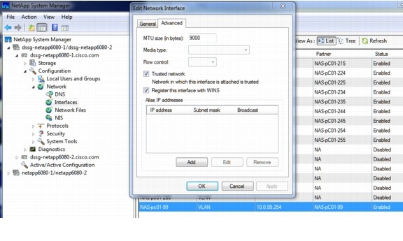
To enable Jumbo Frame support in the NetApp Filer View (web interface), follow these steps:
Step 1 ![]() Click Network > Manager Interface for the desired NetApp.
Click Network > Manager Interface for the desired NetApp.
Step 2 ![]() Enter 9000 in the MTU size box and click Apply.
Enter 9000 in the MTU size box and click Apply.
Figure 2-45 Jumbo Frames in the NetApp Filer Interface

VMware ESXi Host interface (VMKnic)
To create a new VMkernel NIC (VMKnic) with 9000 MTU, follow these steps at the console window:
Step 1 ![]() Make sure a vSwitch is configured on the ESXi Host before configuring the new vmknic. The esxcfg-vmknic command cannot create and map the vmknic to the N1000v port-group:
Make sure a vSwitch is configured on the ESXi Host before configuring the new vmknic. The esxcfg-vmknic command cannot create and map the vmknic to the N1000v port-group:
Example 2-55 VMWare ESXi
esxcfg-vswitch -l
Switch Name Num Ports Used Ports Configured Ports MTU Uplinks
vSwitch0 128 2 128 1500 Not relevant
PortGroup Name VLAN ID Used Ports Uplinks
VM Network 0 1
DVS Name Num Ports Used Ports Configured Ports MTU Uplinks
EAST-N1000V      256         50          256               1500
vmnic9,vmnic8,vmnic7,vmnic6,vmnic5,vmnic4,vmnic3,vmnic2,vmnic1,vmnic0
DVPort ID In Use Client
6868 1 vmnic0
6869 1 vmnic1
6870 1 vmnic2
6871 1 vmnic3
6872 1 vmnic4
6873 1 vmnic5
6874 1 vmnic6
6875 1 vmnic7
6876 1 vmnic8
6877 1 vmnic9
Step 2 ![]() Enter the following commands to create the new vmknic with jumbo frame support that must be attached to a non-Nexus 1000v port-group.
Enter the following commands to create the new vmknic with jumbo frame support that must be attached to a non-Nexus 1000v port-group.
esxcfg-vmknic -a -i <IPaddress> -n <subnet> -m <NNN> -p <port-group name>
In Example 2-56, the VM Network port-group is configured on the VMware vswitch0.
Example 2-56 VMWare ESXi
esxcfg-vmknic -a -i 10.0.99.112 -n 255.255.255.0 -m 9000 -p 'VM Network'
3) Results
vmk5       VM Network          IPv4      10.0.99.112
255.255.255.0   10.0.99.255     00:50:56:7a:b7:8d 9000    65535     true    STATIC
RedHat 5.5 Guest Operating System
To set jumbo frames on an interface in RHEL 5.5 enter the following command for each interface for which you want change the MTU while in super-user root access privilege mode:
ifconfig <interface#> mtu <number>
Example 2-57 RedHate Guest OS
Example: = ifconfig eth2 mtu 9000
ifconfig -l
eth2 Link encap:Ethernet HWaddr 00:50:56:85:00:08
inet addr:192.168.100.22 Bcast:192.168.100.255 Mask:255.255.255.0
inet6 addr: fe80::250:56ff:fe85:8/64 Scope:Link
UP BROADCAST RUNNING MULTICAST MTU:9000 Metric:1
RX packets:0 errors:0 dropped:0 overruns:0 frame:0
TX packets:0 errors:0 dropped:0 overruns:0 carrier:0
collisions:0 txqueuelen:1000
RX bytes:0 (0.0 b) TX bytes:0 (0.0 b)
Jumbo Frame Deployment Guidelines
The following deployment guidelines were identified:
Nexus 7010
When configuring MTU on the Nexus 7000 series, follow these guidelines:
•![]() Configure the system jumbo MTU size, which can be used to specify the MTU size for Layer 2 interfaces. Specify an even number between 1500 and 9216. If not configured, the system jumbo MTU size defaults to 9216 bytes.
Configure the system jumbo MTU size, which can be used to specify the MTU size for Layer 2 interfaces. Specify an even number between 1500 and 9216. If not configured, the system jumbo MTU size defaults to 9216 bytes.
•![]() For Layer 3 interfaces, configure an MTU size that is between 576 and 9216 bytes.
For Layer 3 interfaces, configure an MTU size that is between 576 and 9216 bytes.
•![]() For Layer 2 interfaces, configure all Layer 2 interfaces to use either the default MTU size (1500 bytes) or the system jumbo MTU size (default size of 9216 bytes).
For Layer 2 interfaces, configure all Layer 2 interfaces to use either the default MTU size (1500 bytes) or the system jumbo MTU size (default size of 9216 bytes).
Nexus 5000
When configuring MTU on the Nexus 5000 series, follow these guidelines:
•![]() The system jumbomtu command defines the maximum MTU size for the switch. However, jumbo MTU is only supported for system classes that have MTU configured.
The system jumbomtu command defines the maximum MTU size for the switch. However, jumbo MTU is only supported for system classes that have MTU configured.
•![]() MTU is specified per system class. You cannot configure MTU on the interfaces.
MTU is specified per system class. You cannot configure MTU on the interfaces.
•![]() The system class MTU sets the MTU for all packets in the class. The system class MTU cannot be configured larger than the global jumbo MTU.
The system class MTU sets the MTU for all packets in the class. The system class MTU cannot be configured larger than the global jumbo MTU.
•![]() The FCoE system class (for Fibre Channel and FCoE traffic) has a default MTU of 2240 bytes. This value cannot be modified.
The FCoE system class (for Fibre Channel and FCoE traffic) has a default MTU of 2240 bytes. This value cannot be modified.
Multicast Implementation
In Cisco VMDC 2.1, multicast is implemented in two different ways. In the unprotected zone, Layer 3 multicast (PIM) on the tenant VLANs provides multicast capability intra- and inter-VLAN and external to the rest of the network. In the protected zone, Layer 2 multicast (IGMP) on the VLANs supports only intra-VLAN multicast requirements.
The multicast deployment in Cisco VMDC 2.1 is structured around the following features and configurations at specific locations in the topology:
Core
•![]() PIM (sparse mode)
PIM (sparse mode)
•![]() Anycast RP using MSDP
Anycast RP using MSDP
Unprotected Zone - Intra- and Inter-VLAN
•![]() PIM (sparse mode) for Front End VLANs
PIM (sparse mode) for Front End VLANs
•![]() IGMP Querier deployed at Aggreggation and/or Access Layer for Back End VLANs
IGMP Querier deployed at Aggreggation and/or Access Layer for Back End VLANs
•![]() Static RP
Static RP
•![]() IGMP Snooping
IGMP Snooping
Protected Zone - Intra-VLAN only
•![]() IGMP Querier deployed at Aggregation or Access for Front End VLANs and/or Access Layer for Back End VLANs
IGMP Querier deployed at Aggregation or Access for Front End VLANs and/or Access Layer for Back End VLANs
•![]() IGMP Snooping
IGMP Snooping
Figure 2-46 Multicast Deployment in Layers
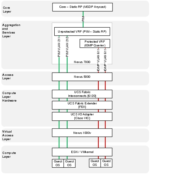
As mentioned in Core Layer, the core design is not a focus of Cisco VMDC 2.1. This section is included for completeness to show an example deployment of a redundant multicast rendezvous point (RP) in the core.
Anycast RP is an implementation strategy that provides load sharing and redundancy in Protocol Independent Multicast sparse mode (PIM-SM) networks. Anycast RP allows two or more rendezvous points (RPs) to share the load for source registration and the ability to act as a backup for each other. Multicast Source Discovery Protocol (MSDP) makes Anycast RP possible.
Figure 2-47 PIM Flows and RPs
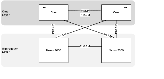
Example 2-58 and Example 2-59 present an example core configuration for MSDP Anycast RP and PIM SM that could be used in a typical Cisco VMDC 2.1 deployment.
Example 2-58 Example Core Configuration for MSDP Anycast RP and PIM SM (Core Nexus 7000 A)
vrf context T1U
ip pim rp-address 10.1.31.101 group-list 239.1.0.0/16
ip pim ssm range none
ip msdp originator-id loopback1
ip msdp peer 10.1.31.16 connect-source loopback1
ip msdp description 10.1.31.16 T1U-MSDP-Peer
ip msdp password 10.1.31.16 3 a667d47acc18ea6b8075c962b95fdeed
!
interface loopback1
description RID for VRF T1U
vrf member T1U
ip address 10.1.31.15/32
ip router ospf 1 area 0.0.0.0
!
interface loopback101
description RP Anycast address for VRF T1U
vrf member T1U
ip address 10.1.31.101/32
ip router ospf 1 area 0.0.0.0
!
interface port-channel1
description L3 PC to CORE2
mtu 9216
interface port-channel1.1
description T1U PC Subif to CORE-B
mtu 9216
encapsulation dot1q 3001
no shutdown
vrf member T1U
no ip redirects
ip address 10.1.28.21/30
ip ospf cost 5
ip ospf network point-to-point
ip router ospf 1 area 0.0.0.0
ip pim sparse-mode
!
interface port-channel101
description L3 Link to EAST-AGG-A
mtu 9216
interface port-channel101.1
description T1U PC Subif to EAST-AGG-A
mtu 9216
encapsulation dot1q 3101
no shutdown
vrf member T1U
no ip redirects
ip address 10.1.28.2/30
ip ospf cost 5
ip ospf network point-to-point
ip router ospf 1 area 0.0.0.0
ip pim sparse-mode
!
interface port-channel102
description L3 Link to EAST-AGG-B
mtu 9216
interface port-channel102.1
description T1U PC Subif to DIST-B
mtu 9216
encapsulation dot1q 3201
no shutdown
vrf member T1U
no ip redirects
ip address 10.1.28.14/30
ip ospf cost 5
ip ospf network point-to-point
ip router ospf 1 area 0.0.0.0
ip pim sparse-mode
Example 2-59 Example Core Configuration for MSDP Anycast RP and PIM SM (Core Nexus 7000 B)
vrf context T1U
ip pim rp-address 10.1.31.101 group-list 239.1.0.0/16
ip pim ssm range none
ip msdp originator-id loopback1
ip msdp peer 10.1.31.15 connect-source loopback1
ip msdp description 10.1.31.15 T1U-MSDP-Peer
ip msdp password 10.1.31.15 3 a667d47acc18ea6b8075c962b95fdeed
!
interface loopback1
description RID for VRF T1U
vrf member T1U
ip address 10.1.31.16/32
ip router ospf 1 area 0.0.0.0
!
interface loopback101
description RP Anycast address for VRF T1U
vrf member T1U
ip address 10.1.31.101/32
ip router ospf 1 area 0.0.0.0
!
interface port-channel1
description L3 PC to CORE1
mtu 9216
interface port-channel1.1
description T1U PC Subif to CORE-A
mtu 9216
encapsulation dot1q 3001
no shutdown
vrf member T1U
no ip redirects
ip address 10.1.28.22/30
ip ospf cost 5
ip ospf network point-to-point
ip router ospf 1 area 0.0.0.0
ip pim sparse-mode
!
interface port-channel101
description L3 Link to EAST-AGG-B
mtu 9216
interface port-channel101.1
description T1U PC Subif to DIST-B
mtu 9216
encapsulation dot1q 3101
no shutdown
vrf member T1U
no ip redirects
ip address 10.1.28.6/30
ip ospf cost 5
ip ospf network point-to-point
ip router ospf 1 area 0.0.0.0
ip pim sparse-mode
!
interface port-channel102
description L3 Link to EAST-AGG-A
mtu 9216
interface port-channel102.1
description T1U PC Subif to CORE-B
mtu 9216
encapsulation dot1q 3201
no shutdown
vrf member T1U
no ip redirects
ip address 10.1.28.10/30
ip ospf cost 5
ip ospf network point-to-point
ip router ospf 1 area 0.0.0.0
ip pim sparse-mode
Aggregation Layer (Nexus 7010)
Unprotected Zone Implementation - Intra- and Inter-VLAN
•![]() PIM (sparse mode) for Front End VLANs
PIM (sparse mode) for Front End VLANs
•![]() Static RP
Static RP
Figure 2-48 Aggregation Layer PIM and RP Design
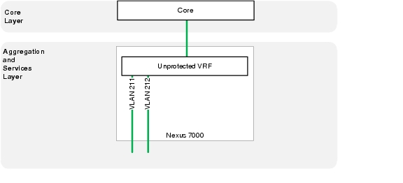
Example 2-60 Layer 3 (PIM) unprotected zone configuration (Nexus 7000 A)
vlan 211
name T1U_Frontend_211
vlan 212
name T1U_Frontend_212
vlan 213
name T1U_Frontend_213
!
vrf context T1U
ip pim rp-address 10.1.31.101 group-list 239.1.0.0/16
ip pim ssm range none
ip pim pre-build-spt
!
interface port-channel1
description T4P PC Subif to VSS-A
mtu 9216
interface port-channel1.1
description T1U PC Subif to DIST-B
mtu 9216
encapsulation dot1q 3001
vrf member T1U
no ip redirects
ip address 10.1.28.17/30
ip ospf cost 5
ip ospf network point-to-point
ip router ospf 1 area 0.0.0.10
ip pim sparse-mode
no shutdown
!
interface port-channel101
description L3 link to EAST-CORE-A
mtu 9216
interface port-channel101.1
description T1U PC Subif to CORE-A
mtu 9216
encapsulation dot1q 3101
vrf member T1U
no ip redirects
ip address 10.1.28.1/30
ip ospf cost 5
ip ospf network point-to-point
ip router ospf 1 area 0.0.0.0
ip pim sparse-mode
no shutdown
!
interface port-channel102
description L3 link to EAST-CORE-B
mtu 9216
interface port-channel102.1
description T1U PC Subif to CORE-B
mtu 9216
encapsulation dot1q 3201
vrf member T1U
no ip redirects
ip address 10.1.28.9/30
ip ospf cost 5
ip ospf network point-to-point
ip router ospf 1 area 0.0.0.0
ip pim sparse-mode
no shutdown
!
interface Vlan211
no shutdown
mtu 9216
description Tenant 1 Unprotected Frontend VLAN
vrf member T1U
no ip redirects
ip address 10.1.1.251/24
ip ospf passive-interface
ip router ospf 1 area 0.0.0.10
ip pim sparse-mode
hsrp 1
preempt delay minimum 120
ip 10.1.1.253
!
interface Vlan212
no shutdown
mtu 9216
description Tenant 1 Unprotected Frontend VLAN
vrf member T1U
no ip redirects
ip address 10.1.2.251/24
ip ospf passive-interface
ip router ospf 1 area 0.0.0.10
ip pim sparse-mode
hsrp 1
preempt delay minimum 120
priority 110
ip 10.1.2.253
!
interface Vlan213
no shutdown
mtu 9216
description Tenant 1 Unprotected Frontend VLAN
vrf member T1U
no ip redirects
ip address 10.1.3.251/24
ip ospf passive-interface
ip router ospf 1 area 0.0.0.10
ip pim sparse-mode
hsrp 1
preempt delay minimum 120
priority 110
ip 10.1.3.253
Example 2-61 Layer 3 (PIM) unprotected zone configuration (Nexus 7000 B)
vlan 211
name T1U_Frontend_211
vlan 212
name T1U_Frontend_212
vlan 213
name T1U_Frontend_213
!
vrf context T1U
ip pim rp-address 10.1.31.101 group-list 239.1.0.0/16
ip pim ssm range none
ip pim pre-build-spt
!
interface port-channel1
description L3 Link to EAST-DIST-A
mtu 9216
interface port-channel1.1
description T1U PC Subif to DIST-A
mtu 9216
encapsulation dot1q 3001
vrf member T1U
no ip redirects
ip address 10.1.28.18/30
ip ospf cost 5
ip ospf network point-to-point
ip router ospf 1 area 0.0.0.10
ip pim sparse-mode
no shutdown
!
interface port-channel101
description L3 link to EAST-CORE-B
mtu 9216
interface port-channel101.1
description T1U PC Subif to CORE-A
mtu 9216
encapsulation dot1q 3101
vrf member T1U
no ip redirects
ip address 10.1.28.5/30
ip ospf cost 5
ip ospf network point-to-point
ip router ospf 1 area 0.0.0.0
ip pim sparse-mode
no shutdown
!
interface port-channel102
description L3 link to EAST-CORE-A
mtu 9216
interface port-channel102.1
description T1U PC Subif to CORE-B
mtu 9216
encapsulation dot1q 3201
vrf member T1U
no ip redirects
ip address 10.1.28.13/30
ip ospf cost 5
ip ospf network point-to-point
ip router ospf 1 area 0.0.0.0
ip pim sparse-mode
no shutdown
!
interface Vlan211
no shutdown
mtu 9216
description Tenant 1 Unprotected Frontend VLAN
vrf member T1U
no ip redirects
ip address 10.1.1.252/24
ip ospf passive-interface
ip router ospf 1 area 0.0.0.10
ip pim sparse-mode
hsrp 1
preempt delay minimum 120
ip 10.1.1.253
!
interface Vlan212
no shutdown
mtu 9216
description Tenant 1 Unprotected Frontend VLAN
vrf member T1U
no ip redirects
ip address 10.1.2.252/24
ip ospf passive-interface
ip router ospf 1 area 0.0.0.10
ip pim sparse-mode
hsrp 1
preempt delay minimum 120
ip 10.1.2.253
!
interface Vlan213
no shutdown
mtu 9216
description Tenant 1 Unprotected Frontend VLAN
vrf member T1U
no ip redirects
ip address 10.1.3.252/24
ip ospf passive-interface
ip router ospf 1 area 0.0.0.10
ip pim sparse-mode
hsrp 1
preempt delay minimum 120
ip 10.1.3.253
Protected Zone Implementation - Intra VLAN only
•![]() IGMP Querier deployed at Aggregation for Front End VLANs
IGMP Querier deployed at Aggregation for Front End VLANs
When a network/VLAN does not have a router that can take on the multicast router role and provide the mrouter discovery on the switches, you can turn on the IGMP querier feature. This feature allows the Layer 2 switch to proxy for a multicast router and sends out periodic IGMP queries in that network. This action causes the switch to consider itself an mrouter port. The remaining switches in the network simply define their respective mrouter ports as the interface on which they received this IGMP query.
Example 2-62 Layer 2 (IGMP Querier) protected zone configuration (Nexus 7000 A)
vlan 611
ip igmp snooping querier 10.1.41.249
name T1P_Frontend_611
!
interface Vlan611
no shutdown
mtu 9216
description Tenant 1 Protected Frontend VLAN
vrf member T1P
no ip redirects
ip address 10.1.41.251/24
ip ospf passive-interface
ip router ospf 1 area 0.0.0.10
hsrp 1
preempt delay minimum 120
ip 10.1.41.253
Example 2-63 Layer 2 (IGMP Querier) protected zone configuration (Nexus 7000 B)
vlan 611
ip igmp snooping querier 10.1.41.250
name T1P_Frontend_611
!
interface Vlan611
no shutdown
mtu 9216
description Tenant 1 Protected Frontend VLAN
vrf member T1P
no ip redirects
ip address 10.1.41.252/24
ip ospf passive-interface
ip router ospf 1 area 0.0.0.10
hsrp 1
preempt delay minimum 120
ip 10.1.41.253
Access Layer (Nexus 5000)
The Nexus 5000 has IGMP snooping enabled by default. With IGMP snooping, the switch snoops (or listens) for IGMP messages on all the ports. The switch builds an IGMP snooping table that basically maps a multicast group to all the switch ports that have requested it.
The IGMP Querier can alternatively be deployed in the Access Layer for Backend VLANs in either the unprotected or protected tenant zones. Backend VLANs do not extend to the aggregation layer so a mrouter must be defined at the access layer.
Example 2-64 Layer 2 (IGMP Querier) protected zone configuration (Nexus 5000 A)
vlan 611
ip igmp snooping querier 10.1.41.249
name T1P_Frontend_611
Example 2-65 Layer 2 (IGMP Querier) protected zone configuration (Nexus 5000 B)
vlan 611
ip igmp snooping querier 10.1.41.250
name T1P_Frontend_611
UCS 6100 Fabric Interconnect
The UCS 6100 has IGMP snooping enabled by default. With IGMP snooping, the switch snoops (or listens) for IGMP messages on all the ports. The switch builds an IGMP snooping table that basically maps a multicast group to all the switch ports that have requested it.
Nexus 1000v
The Nexus 1000v has IGMP snooping enabled by default. With IGMP snooping, the switch snoops (or listens) for IGMP messages on all the ports. The switch builds an IGMP snooping table that basically maps a multicast group to all the switch ports that have requested it.
Multicast Deployment Guidelines
The following deployment guidelines were identified:
vPC
•![]() IGMP snooping-The vPC peers should be configured identically.
IGMP snooping-The vPC peers should be configured identically.
QoS Implementation
This section describes the main categories of the Cisco QoS toolset used in Cisco VMDC 2.1. The following topics are covered at the relevant layers of the VMDC network:
•![]() Classification
Classification
•![]() Marking
Marking
•![]() Queueing
Queueing
Aggregation (Nexus 7010)
The following QoS topics are covered at the Cisco VMDC 2.1 aggregation layer:
•![]() Classification and Marking
Classification and Marking
•![]() Queueing
Queueing
The Cisco Nexus 7000 Series switch supports three types of policies:
•![]() network qos-Defines the characteristics of QoS properties network wide.
network qos-Defines the characteristics of QoS properties network wide.
•![]() qos-Defines MQC objects that you can use for marking and policing.
qos-Defines MQC objects that you can use for marking and policing.
•![]() queuing-Defines MQC objects that you can use for queuing and scheduling as well as a limited set of the marking objects.
queuing-Defines MQC objects that you can use for queuing and scheduling as well as a limited set of the marking objects.
Classification and Marking
Classification tools mark a packet or flow with a specific priority. In Cisco VMDC 2.1 classification sets the packet priority for the datacenter by examining the following:
•![]() Layer 2 Parameters (CoS)
Layer 2 Parameters (CoS)
•![]() Layer 3 Parameters (DSCP or source and destination IP address)
Layer 3 Parameters (DSCP or source and destination IP address)
•![]() Layer 4 Parameters (TCP or UDP ports)
Layer 4 Parameters (TCP or UDP ports)
The marking policy then sets the packet priority based on the DSCP to CoS mappings defined in the policy. The original DSCP value is left unchanged and the CoS is remarked to the desired traffic class.
Figure 2-49 shows the interfaces where the classification and marking policy is applied in the inbound direction. The policy is placed on all of the core facing interfaces as well as all of the services facing interfaces. The classification and marking policy must be created and applied on a per tenant basis.
Figure 2-49 Nexus 7000 Classification and Marking Policy
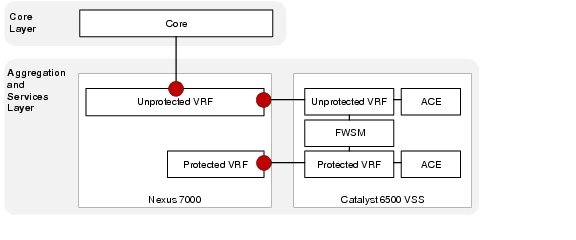
The following configuration shows an example classification and marking policy for Tenant 1:
Example 2-66 Nexus 7000 Classification
! Create object groups based on VM or VIP addresses
!
object-group ip address object-group-protected-VIP
10 10.1.56.0/24
20 10.2.56.0/24
object-group ip address object-group-protected-VM
10 10.1.41.0/24
20 10.1.42.0/24
30 10.1.43.0/24
40 10.2.41.0/24
50 10.2.42.0/24
60 10.2.43.0/24
object-group ip address object-group-unprotected-VIP
10 10.1.24.0/24
20 10.2.24.0/24
object-group ip address object-group-unprotected-VM
10 10.1.1.0/24
20 10.1.2.0/24
30 10.1.3.0/24
40 10.2.1.0/24
50 10.2.2.0/24
60 10.2.3.0/24
!
! Use ACLs to classify the traffic based on applications
!
ip access-list acl-ftp
10 permit tcp any addrgroup object-group-protected-VM range ftp-data ftp
20 permit tcp any addrgroup object-group-unprotected-VM range ftp-data ftp
ip access-list acl-http
10 permit udp any addrgroup object-group-unprotected-VM eq 80
40 permit udp any addrgroup object-group-protected-VIP eq 8080
50 permit udp any addrgroup object-group-unprotected-VIP eq 8080
60 permit udp any addrgroup object-group-protected-VM eq 80
ip access-list acl-https
10 permit tcp any addrgroup object-group-unprotected-VM eq 443
20 permit tcp any addrgroup object-group-unprotected-VIP eq 443
30 permit tcp any addrgroup object-group-protected-VM eq 443
40 permit tcp any addrgroup object-group-protected-VIP eq 443
ip access-list acl-management
10 permit tcp any addrgroup object-group-protected-VM range 22 telnet
20 permit tcp any addrgroup object-group-unprotected-VM range 22 telnet
!
! Use class-maps to classify the traffic
!
class-map type qos match-any class-gold
match access-group name acl-https
class-map type qos match-any class-bronze
match access-group name acl-ftp
class-map type qos match-any class-silver
match access-group name acl-http
class-map type qos match-any class-platinum
match access-group name acl-management
class-map type qos match-any class-scavenger
match dscp 8
class-map type qos match-any class-incoming-cos3
match dscp 24,26,28,30
!
! Create policy map and set the COS values based on traffic class
policy-map type qos ingress-marking
class class-platinum
set cos 5
class class-gold
set cos 4
class class-silver
set cos 2
class class-bronze
set cos 1
class class-scavenger
set cos 0
class class-incoming-cos3
set cos 4
!
! Apply the qos service policy on all port-channel sub-interfaces facing Core
!
interface port-channel101.1
description T1U PC Subif to CORE-A
mtu 9216
encapsulation dot1q 3101
service-policy type qos input ingress-marking
vrf member T1U
no ip redirects
ip address 10.1.28.5/30
ip ospf cost 5
ip ospf network point-to-point
ip router ospf 1 area 0.0.0.0
ip pim sparse-mode
no shutdown
!
interface port-channel102.1
description T1U PC Subif to CORE-B
mtu 9216
encapsulation dot1q 3201
service-policy type qos input ingress-marking
vrf member T1U
no ip redirects
ip address 10.1.28.13/30
ip ospf cost 5
ip ospf network point-to-point
ip router ospf 1 area 0.0.0.0
ip pim sparse-mode
no shutdown
Queuing
Traffic queuing is the ordering of packets and applies to both input and output of data. Device modules can support multiple queues, which are used to control the sequencing of packets in different traffic classes.
In Cisco VMDC 2.1, two queueing considerations exist for the Nexus 7010 at the aggregation layer. The interface queueing policy designed as a 5 queue model and the fabric queueing which is always a 4 queue model.
Table 2-6 shows the Nexus 7000 hardware queuing capabilities for the M1 linecard and the current capabilities for the fabric.
|
|
|
|
|---|---|---|
M1 8-port 10G |
8q2t/1p7q4t |
1p3q1t |
Interface Queuing
Figure 2-50 Nexus 7010 Interfaces for Queuing Policy
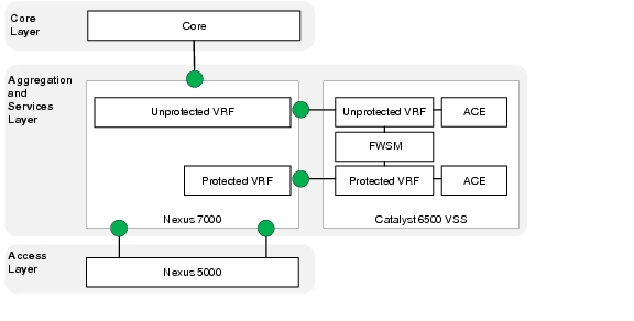
|
|
|
|---|---|
Q1 (Strict Priority) |
5-7 |
Q2 |
2 |
Q4 |
4 |
Q5 |
1 |
Q-Default |
0,3 |
Example 2-67 presents the Nexus 7010 queuing configuration.
Example 2-67 Nexus 7000 Interface Queuing
!Default VDC
!
class-map type queuing match-any 1p7q4t-out-pq1
match cos 5-7
class-map type queuing match-any 1p7q4t-out-q2
match cos 2
class-map type queuing match-any 1p7q4t-out-q4
match cos 4
class-map type queuing match-any 1p7q4t-out-q5
match cos 1
class-map type queuing match-any 1p7q4t-out-q-default
match cos 0,3
!
!Production VDC
!
policy-map type queuing 5-class-egress-queuing-policy
class type queuing 1p7q4t-out-pq1
priority level 1
class type queuing 1p7q4t-out-q4
bandwidth remaining percent 35
class type queuing 1p7q4t-out-q-default
bandwidth remaining percent 20
class type queuing 1p7q4t-out-q5
bandwidth remaining percent 15
class type queuing 1p7q4t-out-q2
bandwidth remaining percent 15
!
interface port-channel1
service-policy type queuing output 5-class-egress-queuing-policy
Fabric Queuing
Cisco Nexus 7000 I/O modules use virtual output queuing (VOQ) to ensure fair access to fabric bandwidth for multiple ingress ports transmitting to one egress port. Four classes of service are available in the switch fabric. The cos-to-queue mapping and the DWRR weights within the fabric cannot be modified. Table 2-8 shows cos-to-queue mapping within the fabric.
|
|
|
|---|---|
Q0 (Strict Priority) |
5-7 |
Q1 |
3-4 |
Q2 |
2 |
Q3 |
0-1 |
Note ![]() Strict priority traffic takes precedence over best-effort traffic across the fabric. Non-strict priority queues are serviced equally as they have the same DWRR weight.
Strict priority traffic takes precedence over best-effort traffic across the fabric. Non-strict priority queues are serviced equally as they have the same DWRR weight.
Datacenter Services Node (Catalyst 6500)
The following topics are covered at the VMDC services layer:
•![]() Queueing
Queueing
Queueing
Traffic queuing is the ordering of packets and applies to both input and output of data. Device modules can support multiple queues, which are used to control the sequencing of packets in different traffic classes.
Table 2-9 shows the Catalyst 6500 hardware queuing capabilities for each type of linecard.
|
|
|
|---|---|
VS-S720-10G |
8q2t/1p3q4t |
WS-X6708-10GE |
8q2t/1p7q4t |
In Cisco VMDC 2.1 the DSN queueing policy is designed as a 4 queue model. Although the capabilities of the WS-X6708 card support more queues the implementation was simplified and implemented drop thresholds on the queues that were used.
|
|
|
|---|---|
Q8 (Strict Priority) |
5 |
Q1 |
1 |
Q2 |
0 |
Q3 |
2,3,4,6,7 |
Example 2-68 presents the Catalyst 6500 queuing configuration.
Example 2-68 Catalyst 6500 VSS Interface Queuing Configuration
! enable qos globally
mls qos
mls qos map cos-dscp 0 8 16 24 32 46 48 56
!
! interface configurations
!
interface TenGigabitEthernet1/2/1
description To DIST-N7010-A-EAST-DIST-A Eth 3/4
no switchport
no ip address
logging event bundle-status
load-interval 30
wrr-queue bandwidth 5 25 70 0 0 0 0
priority-queue queue-limit 20
wrr-queue queue-limit 25 35 20 0 0 0 0
wrr-queue random-detect min-threshold 1 70 100 100 100
wrr-queue random-detect min-threshold 2 80 100 100 100
wrr-queue random-detect min-threshold 3 50 60 80 100
wrr-queue random-detect max-threshold 1 100 100 100 100
wrr-queue random-detect max-threshold 2 100 100 100 100
wrr-queue random-detect max-threshold 3 60 70 80 100
wrr-queue cos-map 1 1 1
wrr-queue cos-map 2 1 0
wrr-queue cos-map 3 1 4
wrr-queue cos-map 3 2 2
wrr-queue cos-map 3 3 3
wrr-queue cos-map 3 4 6 7
no rcv-queue random-detect 1
mls qos trust dscp
channel-group 103 mode active
end
!
interface TenGigabitEthernet2/2/1
description To DIST-N7010-A-EAST-DIST-A Eth 4/4
no switchport
no ip address
logging event bundle-status
load-interval 30
wrr-queue bandwidth 5 25 70 0 0 0 0
priority-queue queue-limit 20
wrr-queue queue-limit 25 35 20 0 0 0 0
wrr-queue random-detect min-threshold 1 70 100 100 100
wrr-queue random-detect min-threshold 2 80 100 100 100
wrr-queue random-detect min-threshold 3 50 60 80 100
wrr-queue random-detect max-threshold 1 100 100 100 100
wrr-queue random-detect max-threshold 2 100 100 100 100
wrr-queue random-detect max-threshold 3 60 70 80 100
wrr-queue cos-map 1 1 1 5
wrr-queue cos-map 2 1 0
wrr-queue cos-map 3 1 4
wrr-queue cos-map 3 2 2
wrr-queue cos-map 3 3 3
wrr-queue cos-map 3 4 6 7
no rcv-queue random-detect 1
mls qos trust dscp
channel-group 103 mode active
end
!
interface TenGigabitEthernet2/3/1
description To DIST-N7010-B-EAST-DIST-B Eth 3/4
no switchport
no ip address
load-interval 30
wrr-queue bandwidth 5 25 70 0 0 0 0
priority-queue queue-limit 20
wrr-queue queue-limit 25 35 20 0 0 0 0
wrr-queue random-detect min-threshold 1 70 100 100 100
wrr-queue random-detect min-threshold 2 80 100 100 100
wrr-queue random-detect min-threshold 3 50 60 80 100
wrr-queue random-detect max-threshold 1 100 100 100 100
wrr-queue random-detect max-threshold 2 100 100 100 100
wrr-queue random-detect max-threshold 3 60 70 80 100
wrr-queue cos-map 1 1 1 5
wrr-queue cos-map 2 1 0
wrr-queue cos-map 3 1 4
wrr-queue cos-map 3 2 2
wrr-queue cos-map 3 3 3
wrr-queue cos-map 3 4 6 7
no rcv-queue random-detect 1
mls qos trust dscp
channel-group 104 mode active
end
!
! show queuing output
!
EAST-VSS-A#sho queueing int ten 1/2/1
Interface TenGigabitEthernet1/2/1 queueing strategy: Weighted Round-Robin
Port QoS is enabled
Trust boundary disabled
Trust state: trust DSCP
Extend trust state: not trusted [COS = 0]
Default COS is 0
Queueing Mode In Tx direction: mode-cos
Transmit queues [type = 1p7q4t]:
Queue Id Scheduling Num of thresholds
-----------------------------------------
01 WRR 04
02 WRR 04
03 WRR 04
04 WRR 04
05 WRR 04
06 WRR 04
07 WRR 04
08 Priority 01
    WRR bandwidth ratios:    5[queue 1]  25[queue 2]  70[queue 3]   0[queue 4]   0[queue
5]   0[queue 6]   0[queue 7]
    queue-limit ratios:     25[queue 1]  35[queue 2]  20[queue 3]   0[queue 4]   0[queue
5]   0[queue 6]   0[queue 7]  20[Pri Queue]
queue tail-drop-thresholds
--------------------------
1 70[1] 100[2] 100[3] 100[4]
2 70[1] 100[2] 100[3] 100[4]
3 100[1] 100[2] 100[3] 100[4]
4 100[1] 100[2] 100[3] 100[4]
5 100[1] 100[2] 100[3] 100[4]
6 100[1] 100[2] 100[3] 100[4]
7 100[1] 100[2] 100[3] 100[4]
queue random-detect-min-thresholds
----------------------------------
1 70[1] 100[2] 100[3] 100[4]
2 80[1] 100[2] 100[3] 100[4]
3 50[1] 60[2] 80[3] 100[4]
4 100[1] 100[2] 100[3] 100[4]
5 100[1] 100[2] 100[3] 100[4]
6 100[1] 100[2] 100[3] 100[4]
7 100[1] 100[2] 100[3] 100[4]
queue random-detect-max-thresholds
----------------------------------
1 100[1] 100[2] 100[3] 100[4]
2 100[1] 100[2] 100[3] 100[4]
3 60[1] 70[2] 80[3] 100[4]
4 100[1] 100[2] 100[3] 100[4]
5 100[1] 100[2] 100[3] 100[4]
6 100[1] 100[2] 100[3] 100[4]
7 100[1] 100[2] 100[3] 100[4]
WRED disabled queues: 4 5 6 7
queue thresh cos-map
---------------------------------------
1 1 1
1 2
1 3
1 4
2 1 0
2 2
2 3
2 4
3 1 4
3 2 2
3 3 3
3 4 6 7
4 1
4 2
4 3
4 4
5 1
5 2
5 3
5 4
6 1
6 2
6 3
6 4
7 1
7 2
7 3
7 4
8 1 5
queue thresh dscp-map
---------------------------------------
    1     1      0 1 2 3 4 5 6 7 8 9 11 13 15 16 17 19 21 23 25 27 29 31 33 39 41 42 43 44
45 47
1 2
1 3
1 4
2 1 14
2 2 12
2 3 10
2 4
3 1 22
3 2 20
3 3 18
3 4
4 1 24 30
4 2 28
4 3 26
4 4
5 1 32 34 35 36 37 38
5 2
5 3
5 4
6 1 48 49 50 51 52 53 54 55 56 57 58 59 60 61 62 63
6 2
6 3
6 4
7 1
7 2
7 3
7 4
8 1 40 46
Queueing Mode In Rx direction: mode-cos
Receive queues [type = 8q4t]:
Queue Id Scheduling Num of thresholds
-----------------------------------------
01 WRR 04
02 WRR 04
03 WRR 04
04 WRR 04
05 WRR 04
06 WRR 04
07 WRR 04
08 WRR 04
    WRR bandwidth ratios:  100[queue 1]   0[queue 2]   0[queue 3]   0[queue 4]   0[queue
5]   0[queue 6]   0[queue 7]   0[queue 8]
    queue-limit ratios:    100[queue 1]   0[queue 2]   0[queue 3]   0[queue 4]   0[queue
5]   0[queue 6]   0[queue 7]   0[queue 8]
queue tail-drop-thresholds
--------------------------
1 100[1] 100[2] 100[3] 100[4]
2 100[1] 100[2] 100[3] 100[4]
3 100[1] 100[2] 100[3] 100[4]
4 100[1] 100[2] 100[3] 100[4]
5 100[1] 100[2] 100[3] 100[4]
6 100[1] 100[2] 100[3] 100[4]
7 100[1] 100[2] 100[3] 100[4]
8 100[1] 100[2] 100[3] 100[4]
queue random-detect-min-thresholds
----------------------------------
1 40[1] 40[2] 50[3] 50[4]
2 100[1] 100[2] 100[3] 100[4]
3 100[1] 100[2] 100[3] 100[4]
4 100[1] 100[2] 100[3] 100[4]
5 100[1] 100[2] 100[3] 100[4]
6 100[1] 100[2] 100[3] 100[4]
7 100[1] 100[2] 100[3] 100[4]
8 100[1] 100[2] 100[3] 100[4]
queue random-detect-max-thresholds
----------------------------------
1 70[1] 80[2] 90[3] 100[4]
2 100[1] 100[2] 100[3] 100[4]
3 100[1] 100[2] 100[3] 100[4]
4 100[1] 100[2] 100[3] 100[4]
5 100[1] 100[2] 100[3] 100[4]
6 100[1] 100[2] 100[3] 100[4]
7 100[1] 100[2] 100[3] 100[4]
8 100[1] 100[2] 100[3] 100[4]
WRED disabled queues: 1 2 3 4 5 6 7 8
queue thresh cos-map
---------------------------------------
1 1 0 1 2 3 4 5 6 7
1 2
1 3
1 4
2 1
2 2
2 3
2 4
3 1
3 2
3 3
3 4
4 1
4 2
4 3
4 4
5 1
5 2
5 3
5 4
6 1
6 2
6 3
6 4
7 1
7 2
7 3
7 4
8 1
8 2
8 3
8 4
queue thresh dscp-map
---------------------------------------
    1     1      0 1 2 3 4 5 6 7 8 9 11 13 15 16 17 19 21 23 25 27 29 31 33 39 41 42 43 44
45 47
1 2
1 3
1 4
2 1 14
2 2 12
2 3 10
2 4
3 1 22
3 2 20
3 3 18
3 4
4 1 24 30
4 2 28
4 3 26
4 4
5 1 32 34 35 36 37 38
5 2
5 3
5 4
6 1 48 49 50 51 52 53 54 55 56 57 58 59 60 61 62 63
6 2
6 3
6 4
7 1
7 2
7 3
7 4
8 1 40 46
8 2
8 3
8 4
Packets dropped on Transmit:
BPDU packets: 0
queue dropped [cos-map]
---------------------------------------------
1 0 [1 ]
2 0 [0 ]
3 0 [4 2 3 6 7 ]
8 0 [5 ]
Packets dropped on Receive:
BPDU packets: 0
queue dropped [cos-map]
---------------------------------------------
1 0 [0 1 2 3 4 5 6 7 ]
EAST-VSS-A#
Access (Nexus 5000)
The following topics are covered at the VMDC access layer:
•![]() Classification
Classification
•![]() Marking
Marking
•![]() Queueing
Queueing
The Cisco Nexus 5000 Series switch supports three policy types. The following QoS parameters can be specified in policy maps for each type of class:
•![]() network-qos-A network-qos policy is used to instantiate system classes and associate parameters with those classes that are of system-wide scope.
network-qos-A network-qos policy is used to instantiate system classes and associate parameters with those classes that are of system-wide scope.
•![]() queuing-A type queuing policy is used to define the scheduling characteristics of the queues associated with system classes.
queuing-A type queuing policy is used to define the scheduling characteristics of the queues associated with system classes.
•![]() qos-A type qos policy is used to classify traffic that is based on various Layer 2, Layer 3, and Layer 4 fields in the frame and to map it to system classes.
qos-A type qos policy is used to classify traffic that is based on various Layer 2, Layer 3, and Layer 4 fields in the frame and to map it to system classes.
Classification
A type qos policy map is used to classify traffic that is based on various Layer 2, Layer 3, and Layer 4 fields in the frame and to map it to system classes. The traffic that matches this class are as follows:
•![]() Class of Service-Matches traffic based on the CoS field in the frame header.
Class of Service-Matches traffic based on the CoS field in the frame header.
•![]() Access Control Lists-Classifies traffic based on the criteria in existing ACLs.
Access Control Lists-Classifies traffic based on the criteria in existing ACLs.
To classify packets based on incoming CoS use the following system-level configuration:
Example 2-69 Nexus 5000 Classification of incoming CoS
class-map type qos class-fcoe
class-map type qos match-any class-gold
match cos 4
class-map type qos match-all class-bronze
match cos 1
class-map type qos match-all class-silver
match cos 2
class-map type qos match-all class-platinum
match cos 5
!
policy-map type qos system-level-qos
class class-platinum
set qos-group 5
class class-gold
set qos-group 4
class class-silver
set qos-group 3
class class-bronze
set qos-group 2
!
class-map type network-qos class-gold
match qos-group 4
class-map type network-qos class-bronze
match qos-group 2
class-map type network-qos class-silver
match qos-group 3
class-map type network-qos class-platinum
match qos-group 5
class-map type network-qos class-all-flood
match qos-group 2
class-map type network-qos class-ip-multicast
match qos-group 2
!
system qos
service-policy type qos input system-level-qos
To classify packets coming from an externally attached device using ACLs use the following interface level configuration:
Example 2-70 Nexus 5000 external classification based on ACL
ip access-list class-bronze-acl
10 permit ip 10.7.1.212/32 any
ip access-list class-gold-acl
10 permit ip 10.7.1.214/32 any
ip access-list class-platinum-acl
10 permit ip 10.7.1.215/32 any
ip access-list class-silver-acl
10 permit ip 10.7.1.213/32 any
!
class-map type qos match-all class-gold-external
match access-group name class-gold-acl
class-map type qos match-all class-bronze-external
match access-group name class-bronze-acl
class-map type qos match-all class-silver-external
match access-group name class-silver-acl
class-map type qos match-all class-platinum-external
match access-group name class-platinum-acl
!
policy-map type qos external-input-policy
class class-platinum-external
set qos-group 5
class class-gold-external
set qos-group 4
class class-silver-external
set qos-group 3
class class-bronze-external
set qos-group 2
!
interface port-channel4
description vpc netapp6080-1-7a
switchport mode trunk
vpc 4
switchport trunk allowed vlan 14,99,214-215
spanning-tree port type edge trunk
service-policy type qos input external-input-policy
!
interface port-channel5
description vpc netapp6080-2-7a
switchport mode trunk
vpc 5
switchport trunk allowed vlan 14,99,214-215
spanning-tree port type edge trunk
service-policy type qos input external-input-policy
Marking
A network-qos policy is used to instantiate system classes and associate parameters with those classes that are of system-wide scope. The actions that are performed on the matching traffic are as follows:
•![]() MTU-The MTU that needs to be enforced for the traffic that is mapped to a system class. Each system class has a default MTU and the system class MTU is configurable.
MTU-The MTU that needs to be enforced for the traffic that is mapped to a system class. Each system class has a default MTU and the system class MTU is configurable.
•![]() Queue Limit-This configuration specifies the number of buffers that need to be reserved to the queues of this system class. This option is not configurable for no-drop system classes.
Queue Limit-This configuration specifies the number of buffers that need to be reserved to the queues of this system class. This option is not configurable for no-drop system classes.
•![]() Set CoS value-This configuration is used to mark 802.1p values for all traffic mapped to this system class.
Set CoS value-This configuration is used to mark 802.1p values for all traffic mapped to this system class.
To set queue-limits, MTU, and CoS values use the following system configuration:
Example 2-71 EAST-N5020-A
system jumbomtu 9216
!
class-map type network-qos class-gold
match qos-group 4
class-map type network-qos class-bronze
match qos-group 2
class-map type network-qos class-silver
match qos-group 3
class-map type network-qos class-platinum
match qos-group 5
!
policy-map type network-qos system-level-qos
class type network-qos class-platinum
queue-limit 30000 bytes
mtu 9216
set cos 5
class type network-qos class-gold
queue-limit 30000 bytes
mtu 9216
set cos 4
class type network-qos class-silver
queue-limit 30000 bytes
mtu 9216
set cos 2
class type network-qos class-bronze
queue-limit 30000 bytes
mtu 9216
set cos 1
class type network-qos class-fcoe
pause no-drop
mtu 2158
class type network-qos class-default
mtu 9216
!
system qos
service-policy type network-qos system-level-qos
Queueing
A type queuing policy is used to define the scheduling characteristics of the queues associated with system classes. The actions that are performed on the matching traffic are as follows:
•![]() Bandwidth-Sets the guaranteed scheduling deficit weighted round robin (DWRR) percentage for the system class.
Bandwidth-Sets the guaranteed scheduling deficit weighted round robin (DWRR) percentage for the system class.
•![]() Priority-Sets a system class for strict-priority scheduling. Only one system class can be configured for priority in a given queuing policy.
Priority-Sets a system class for strict-priority scheduling. Only one system class can be configured for priority in a given queuing policy.
In Cisco VMDC 2.1 the Nexus 5000 queueing is designed a 5 class model. The use of CoS 3 is removed and reserved for future use of Fibre Channel over Ethernet.
|
|
|
|---|---|
5 (Platinum) |
5 |
4 (Gold) |
4 |
2 (Silver) |
2 |
1 (Bronze) |
1 |
Default |
0 |
Example 2-72 Nexus 5000 Queuing
class-map type queuing class-gold
match qos-group 4
class-map type queuing class-bronze
match qos-group 2
class-map type queuing class-silver
match qos-group 3
class-map type queuing class-platinum
match qos-group 5
class-map type queuing class-all-flood
match qos-group 2
class-map type queuing class-ip-multicast
match qos-group 2
!
policy-map type queuing egress_queueing_policy
class type queuing class-platinum
priority
class type queuing class-gold
bandwidth percent 20
class type queuing class-silver
bandwidth percent 20
class type queuing class-bronze
bandwidth percent 20
class type queuing class-fcoe
bandwidth percent 0
class type queuing class-default
bandwidth percent 40
!
system qos
service-policy type queuing output egress_queueing_policy
Compute Layer Hardware (UCS 6100 FI)
System Classes
Cisco UCS uses Data Center Ethernet (DCE) to handle all traffic inside a Cisco UCS system. This industry standard enhancement to Ethernet divides the bandwidth of the Ethernet pipe into eight virtual lanes. System classes determine how the DCE bandwidth in these virtual lanes is allocated across the entire Cisco UCS system.
Each system class reserves a specific segment of the bandwidth for a specific type of traffic. This provides a level of traffic management, even in an oversubscribed system.
Figure 2-51 System Class Definitions in Cisco UCSM
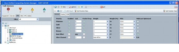
Virtual Access (Nexus 1000v)
The following topics are covered at the VMDC virtual access layer:
•![]() Classification
Classification
•![]() Marking
Marking
Classification and Marking
As a best practice, identify and mark traffic (with COS and/or DSCP values) as close to the source as possible. On the Nexus 1000v, this marking is performed using the ingress port-profile that is applied to the VM interfaces.
The configuration below shows an example for marking traffic on a Frontend, Backend, and management VM interface.
Example 2-73 Nexus 1000v
! FRONT END APPLICATION TRAFFIC
!
ip access-list http
10 permit tcp any any eq www
class-map type qos match-all http_cos4
match access-group name http
!
policy-map type qos PUBLIC
class http_cos4
set cos 4
set dscp 34
class class-default
!
port-profile type vethernet T01U211
vmware port-group
switchport mode access
switchport access vlan 211
service-policy type qos input PUBLIC
no shutdown
description UnProtected Access Vlan211 Tenant#1
state enabled
!
! BACK END APPLICATION TRAFFIC
!
ip access-list nfs
10 permit tcp any any eq 2049
!
class-map type qos match-all nfs_cos5
match access-group name nfs
!
policy-map type qos PRIVATE
class nfs_cos5
set cos 5
set dscp 46
class class-default
!
port-profile type vethernet T01NJ215
capability l3control
vmware port-group
switchport mode access
switchport access vlan 215
pinning id 10
service-policy input PRIVATE
no shutdown
description Tenant_1_NAS_jumbo_frame
state enabled
!
! MANAGEMENT TRAFFIC
!
ip access-list mgmt_COS1
10 permit ip 10.0.34.0/24 any
ip access-list mgmt_COS2
30 permit ip 10.0.33.0/24 any
!
class-map type qos match-all mgmt_COS1
match access-group name mgmt_COS1
class-map type qos match-all mgmt_COS2
match access-group name mgmt_COS2
!
policy-map type qos mgmt
class mgmt_COS1
set cos 1
set dscp 10
class mgmt_COS2
set cos 2
set dscp 16
class class-default
!
port-profile type vethernet MGMT33
capability l3control
vmware port-group
switchport mode access
switchport access vlan 33
service-policy type qos input mgmt
no shutdown
system vlan 33
description Management Network - UCS (KVM/ESXi) Devices
state enabled
!
port-profile type vethernet MGMT34
vmware port-group
switchport mode access
switchport access vlan 34
pinning id 6
service-policy type qos input mgmt
no shutdown
max-ports 1024
description Management Network - EAST Spirent Virtual Machines
state enabled
UCS M81KR (Palo)
The following topic is covered at the UCS Hardware layer:
•![]() Queueing
Queueing
UCS QoS Policy
In the case where the Nexus 1000v is doing the CoS/DSCP marking, a special mode of operation termed as the "Trusted-CoS" mode is supported on the M81KR which sets the adapter to essentially "Pass-through" mode.
In this mode, the queuing behavior on the M81KR adapter is changed. The number of queues in this mode is reduced to 3: one is for control, one for FC, and one for Ethernet in which traffic from all Ethernet vNICs is directed.
This mode is enabled by choosing the Host Control as Full in the QoS policy, which is applied to a vNIC.
Figure 2-52 QoS policy setting the Trust Mode (only applicable to the M81KR)
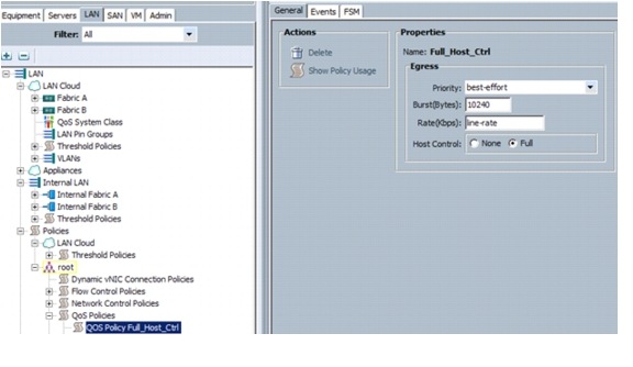
QoS Deployment Guidelines
The following deployment guidelines were identified:
Nexus 5000
•![]() Optimized multicasting allows use of the unused multicast queues to achieve better throughput for multicast frames. If optimized multicast is enabled for the default drop system class, the system will use all six queues to service the multicast traffic (all six queues are given equal priority).
Optimized multicasting allows use of the unused multicast queues to achieve better throughput for multicast frames. If optimized multicast is enabled for the default drop system class, the system will use all six queues to service the multicast traffic (all six queues are given equal priority).
Additional Product Implementation
The following products were highlighted in Cisco VMDC 2.1:
•![]() Network Analysis Module (NAM) for Nexus 1010
Network Analysis Module (NAM) for Nexus 1010
Network Analysis Module (NAM) for Nexus 1010
Cisco Nexus 1000v NAM VSB is integrated with the Nexus 1010 Virtual Services Appliance to provide network and performance visibility into the Nexus 1000V switching deployment. The NAM VSB uses the embedded instrumentation, such as Encapsulated Remote SPAN (ERSPAN) and NetFlow on the Nexus 1000V switch as the data source for traffic analysis, application response time, interface statistics, and reporting.
For more information on the Cisco Prime NAM for Nexus 1010 deployment follow the link below:
In Cisco VMDC 2.1, the key focus features of the Cisco Prime NAM for Nexus 1010 include:
•![]() NetFlow - Traffic analysis
NetFlow - Traffic analysis
•![]() ERSPAN - Packet Capture, Decode, Filters and Error scan
ERSPAN - Packet Capture, Decode, Filters and Error scan
Nexus 1010 Deployment
Referring back to Nexus 1010 Virtual Service Appliance, the Nexus 1010 is deployed using Option 3.
The chosen deployment scenario uses the two lights-out management (LOM) interfaces for management traffic, and the four interfaces on the PCI card carry control, packet, and data traffic. This option is ideal for deploying additional virtual service blades like a Network Analysis Module (NAM).
The VLAN allocation and the Nexus 1010 configurations for the following VLANs are relevant for the NAM deployment:
The virtual service blades must be installed on VLAN 33 to ensure that the traffic to and from the NAM uses the vPC on the Nexus 5000 and Nexus 1010 instead of the management (LOM) ports. Figure 2-53 shows a single Nexus 1010 in the management layer with the VLANs on the correct interfaces for reference.
Figure 2-53 Nexus 1010 in the Management Layer
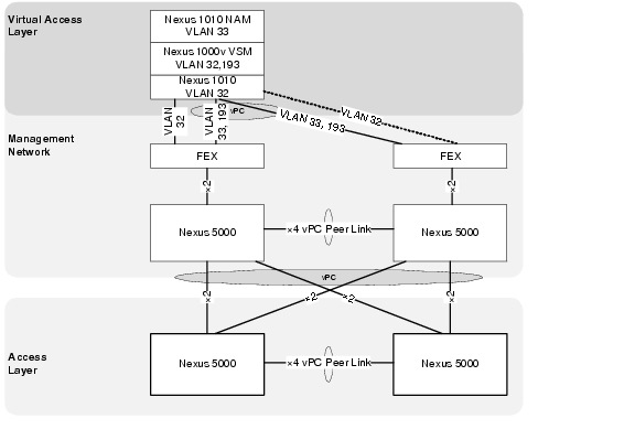
Virtual Service Blade (VSB) Installation
The NAM must first be installed and configured on the Nexus 1010 Virtual Service Appliance as illustrated in Example 2-74.
Example 2-74 NAM Installation Details
EAST-N1010-A# dir bootflash:/repository
...
159250432 Jun 08 08:03:19 2011 nam-app-x86_64.4-2-1n.iso
...
Usage for bootflash://sup-local
348807168 bytes used
3642572800 bytes free
3991379968 bytes total
!
!Configuration Steps
!
EAST-N1010-A (config) virtual-service-blade EAST-NAM
EAST-N1010-A (config-vb-config)# virtual-service-blade-type new nam-4-2-1.iso
EAST-N1010-A (config-vb-config)# interface data vlan 33
EAST-N1010-A (config-vb-config)# enable
Enter vsb image:[nam-4-2-1.iso]
Enter Management IPV4 address: 10.0.33.14
Enter Management subnet mask: 255.255.255.255
IPv4 address of the default gateway: 10.0.33.1
Enter Hostname: EAST-NAM
Setting Web user/passwd will enable port 80. Press Enter[y/n]:y
Web User name: [admin]
Web User password: admin
Once installed the virtual service blade should be part of the Nexus 1010 configuration.
Example 2-75 Nexus 1010 Configuration with NAM
EAST-N1010-A# sho running-config
!Command: show running-config
!Time: Tue Jul 26 09:33:00 2011
version 4.2(1)SP1(2)
feature telnet
no feature http-server
!
username admin password 5 $1$B6FT6lup$cU51UaxAMIjZJHqviGGLB. role network-admin
no password strength-check
!
banner motd #Nexus 1010#
!
ip domain-lookup
ip domain-lookup
switchname EAST-N1010-A
snmp-server user admin network-admin auth md5 0x3b8f01b4aeaa4fd0c8fd99a220d527e2
priv 0x3b8f01b4aeaa4fd0c8fd99a220d527e2 localizedkey
snmp-server community public group network-operator
!
vrf context management
ip route 0.0.0.0/0 10.0.32.1
vlan 1,32,300
port-channel load-balance ethernet source-mac
port-profile default max-ports 32
!
vdc EAST-N1010-A id 1
limit-resource vlan minimum 16 maximum 2049
limit-resource monitor-session minimum 0 maximum 2
limit-resource vrf minimum 16 maximum 8192
limit-resource port-channel minimum 0 maximum 768
limit-resource u4route-mem minimum 32 maximum 32
limit-resource u6route-mem minimum 16 maximum 16
limit-resource m4route-mem minimum 58 maximum 58
limit-resource m6route-mem minimum 8 maximum 8
network-uplink type 3
virtual-service-blade EAST-N1000V-VSM
virtual-service-blade-type name VSM-1.1
interface control vlan 193
interface packet vlan 193
ramsize 2048
disksize 4
numcpu 1
cookie 145749956
no shutdown primary
no shutdown secondary
virtual-service-blade EAST-NAM
virtual-service-blade-type name NAM-1.1
interface data vlan 33
ramsize 2048
disksize 53
numcpu 2
cookie 2062757272
no shutdown primary
!
interface mgmt0
ip address 10.0.32.110/24
!
interface control0
line console
boot kickstart bootflash:/nexus-1010-kickstart-mz.4.2.1.SP1.2.bin
boot system bootflash:/nexus-1010-mz.4.2.1.SP1.2.bin
boot kickstart bootflash:/nexus-1010-kickstart-mz.4.2.1.SP1.2.bin
boot system bootflash:/nexus-1010-mz.4.2.1.SP1.2.bin
svs-domain
domain id 300
control vlan 300
management vlan 32
svs mode L2
vnm-policy-agent
registration-ip 0.0.0.0
shared-secret **********
log-level info
logging server 172.18.177.178 7 facility local4
logging timestamp milliseconds
logging monitor 7
logging level local4 6
After the NAM is installed and configured the NAM IP address can be typed in a browser to access the NAM Traffic Analyzer GUI and set up a managed device.
Figure 2-54 NAM Traffic Analyzer Web Interface
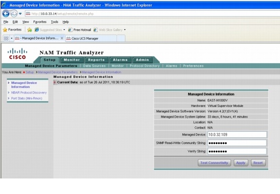
NetFlow
NetFlow Data Export (NDE) records offer an aggregate view of the network. When enabled on the local/remote switch, the NetFlow data source becomes available on the NAM without the need to create any SPAN sessions. The Cisco NAM can get detailed information on the packets through the NDE records without having to examine each packet, and hence more traffic can be analyzed. However, NetFlow only gives statistics for applications, hosts, and conversations. Detailed monitoring for voice, VLAN, IAP, DiffServ, and packet captures and decodes are not available with NetFlow.
To use Nexus 1000v device as an NDE data source for the NAM, the switch should be configured to export NDE packets to UDP port 3000 on the NAM.
Example 2-76 Nexus 1000v Configuration
!enable netflow
feature netflow
!
!create exporter and monitor
flow exporter test
description EAST N1Kv Exporter
destination 10.0.33.14 use-vrf management
transport udp 3000
source mgmt0
dscp 16
version 9
flow monitor test
description management flow monitor
record netflow-original
exporter test
timeout active 1800
cache size 4096
!
! apply netflow to a port profile
port-profile type vethernet MGMT33
capability l3control
vmware port-group
switchport mode access
switchport access vlan 33
service-policy type qos input mgmt
ip flow monitor test input
ip flow monitor test output
no shutdown
system vlan 33
description Management Network - UCS (KVM/ESXi) Devices
state enabled
NetFlow data sources are automatically learned when you create a device in the Devices section.
Figure 2-55 NetFlow Data Source in NAM Traffic Analyzer
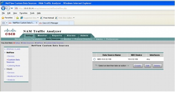
The NetFlow Data Records should start to populate in the Monitoring tab.
Figure 2-56 NetFlow in the Monitoring Tab
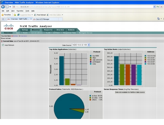
And either Basic or Custom historical reports can be created.
Figure 2-57 NetFlow Reports in the NAM Traffic Analyzer
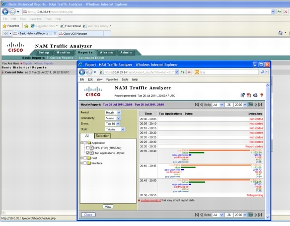
ERSPAN
To send the data directly to the NAM management IP address (data vlan), configure the ERSPAN source session on the Nexus 1000v. No ERSPAN destination session configuration is required on the NAM. After performing this configuration on the switch, the ERSPAN data source should appear on the NAM GUI and can then be selected to analyze the ERSPAN traffic.
An example ERSPAN monitor session configuration on the Nexus 1000v is illustrated in Example 2-77.
Example 2-77 Nexus 1000v ERSPAN Configuration
! enable l3control on the port-profile
!
EAST-N1000V(config-port-prof)# show run port-profile T01U211
port-profile type vethernet T01U211
capability l3control
vmware port-group
switchport mode access
switchport access vlan 211
no shutdown
description UnProtected Access Vlan211 Tenant#1
state enabled
!
! create monitor session
EAST-N1000V(config)# sho run | begin erspan-source
monitor session 1 type erspan-source
source port-profile T01U211 both
destination ip 10.0.33.14
erspan-id 1
ip ttl 64
ip prec 0
ip dscp 0
mtu 1500
header-type 2
no shut
!
EAST-N1000V(config)# show monitor session 1
session 1
---------------
type : erspan-source
state : up
source intf :
rx :
tx :
both :
source VLANs :
rx :
tx :
both :
source port-profile :
rx : T01U211
tx : T01U211
both : T01U211
filter VLANs : filter not specified
destination IP : 10.0.33.14
ERSPAN ID : 1
ERSPAN TTL : 64
ERSPAN IP Prec. : 0
ERSPAN DSCP : 0
ERSPAN MTU : 1500
ERSPAN Header Type: 2
Once the monitor session is setup the ERSPAN sessions should be seen in the NAM GUI and overview statics should be seen.
Figure 2-58 ERSPAN in the NAM Traffic Analyzer
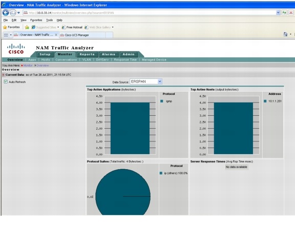
From there selecting ERSPAN as a Data Source will allow operations like packet capturing, real time reporting, and host or protocol details.
Figure 2-59 ERSPAN Data Source Selection in the NAM Traffic Analyzer
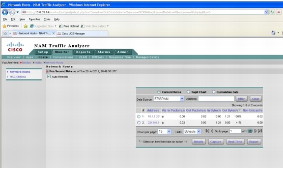
And either Basic or Custom historical reports can be created.
Figure 2-60 Example ERSPAN Report in NAM Traffic Analyzer
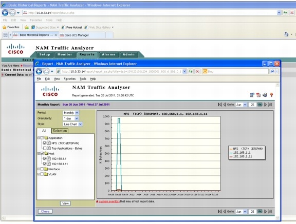
NAM Deployment Guidelines
The following NAM deployment guidelines were identified:
•![]() The NAM data VLAN is used for both management and data (packet) collection for the virtual NAM. Unlike the Nexus 1000v VSM, the virtual NAM does not inherit the management VLAN from the VSB. The IP address assigned to the NAM must be in the data VLAN.
The NAM data VLAN is used for both management and data (packet) collection for the virtual NAM. Unlike the Nexus 1000v VSM, the virtual NAM does not inherit the management VLAN from the VSB. The IP address assigned to the NAM must be in the data VLAN.
 Feedback