Deploying QoS for Application Performance Optimization
Expectations have evolved significantly over the past few years as users and endpoints use the network in ever-evolving ways and increasingly expect guaranteed low latency bandwith. Application and device awareness have become key tools in providing differentiated service treatment at the campus edge. Media applications, particularly video-oriented media applications, are evolving as the enterprise network conducts business digitally. There are also increased campus network and asset security requirements. Integrating video applications in the enterprise campus network exponentially increases bandwidth utilization and fundamentally shifts traffic patterns. Business drivers behind this media application growth include remote business operations, as well as leveraging the network as a platform to build an energy-efficient network to minimize cost and go “green”. High-definition media is transitioning from the desktop to conference rooms and social networking phenomena are crossing over into enterprise settings. Besides internal and enterprise research applications, media applications are fueling a new wave of IP convergence, requiring the ongoing development of converged network designs.
Converging media applications onto an IP network is much more complex than converging voice over IP (VoIP). Media applications are diverse, generally bandwidth-intensive, and bursty (as compared to VoIP). In addition to IP telephony, applications can include live and on-demand streaming media applications, digital signage applications, high-definition room-based conferencing applications, as well as an infinite array of data-oriented applications. By embracing media applications as the next cycle of convergence, enterprise IT departments can think holistically about their network design and its readiness to support the coming tidal wave of media applications and develop a network-wide strategy to ensure a high quality end user experiences.
The Borderless Campus infrastructure must set administrative policies to provide differentiated forwarding services to network applications, users, and endpoints to prevent contention. The characteristics of network services and applications must be well understood so that policies can be defined that allow network resources to be used for internal applications, to provide best-effort services for external traffic, and to keep the network protected from threats.
Policies for providing network resources to an internal application are further complicated when interactive video and real-time VoIP applications are converged over the same network that is switching mid-to-low priority data traffic. Deploying QoS technologies in the campus allows different types of traffic to contend inequitably for network resources. Real-time applications such as voice, interactive, and physical security video can be given priority or preferential services over generic data applications, but not to the point that data applications are starved for bandwidth.
Enterprise Campus QoS Framework
Each group of managed and un-managed applications with unique traffic patterns and service level requirements requires a dedicated QoS class to provision and guarantee these service level requirements. The enterprise campus network architect may need to determine the number of classes for various applications, as well as how these individual classes should be implemented to consistently deliver differentiated services in main and remote campus sites. Cisco recommends following the relevant industry standards and guidelines whenever possible to extend the effectiveness of your QoS policies beyond your direct administrative control.
With minor changes, the enterprise campus QoS framework is developed based on RFC4594 that follows industry standard and guidelines to function consistently in heterogeneous network environments. These guidelines are to be viewed as industry best-practice recommendations. Enterprise organizations and service providers are encouraged to adopt these marking and provisioning recommendations with the aim of improving QoS consistency, compatibility, and interoperability. However, because these guidelines are not standards, modifications can be made to these recommendations as specific needs or constraints require. To this end, to meet specific business requirements, Cisco has made a minor modification to its adoption of RFC 4594, namely the switching of call signaling and broadcast video markings (to CS3 and CS5, respectively).
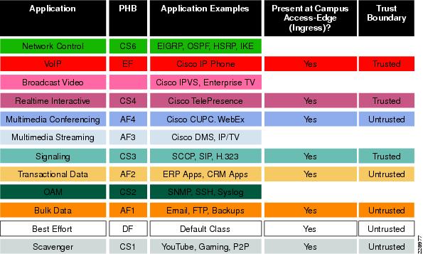
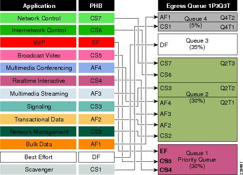
RFC 4594 outlines twelve classes of media applications that have unique service level requirements, as shown in Figure 1-1.
Figure 1-1 Campus 12-Class QoS Policy Recommendation
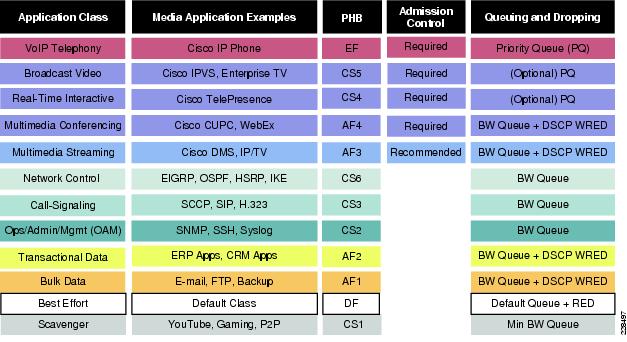
- VoIP telephony—This service class is intended for VoIP telephony (bearer only) traffic (VoIP signaling traffic is assigned to the call signaling class). Traffic assigned to this class should be marked EF. This class is provisioned with expedited forwarding (EF) per-hop behavior (PHB). The EF PHB defined in RFC 3246 is a strict priority queuing service and, as such, admission to this class should be controlled (admission control is discussed in the following section). Examples of this type of traffic include G.711 and G.729a.
- Broadcast video—This service class is intended for broadcast TV, live events, video surveillance flows, and similar inelastic streaming video flows, which are highly drop sensitive and have no retransmission and/or flow control capabilities. Traffic in this class should be marked class selector 5 (CS5) and may be provisioned with an EF PHB; as such, admission to this class should be controlled. Examples of this traffic include live Cisco Digital Media System (DMS) streams to desktops or to Cisco Digital Media Players (DMPs), live Cisco Enterprise TV (ETV) streams, and Cisco IP Video Surveillance.
- Real-time interactive—This service class is intended for (inelastic) room-based, high-definition interactive video applications and is intended primarily for the voice and video components of these applications. Whenever technically possible and administratively feasible, data sub-components of this class can be separated out and assigned to the transactional data traffic class. Traffic in this class should be marked CS4 and may be provisioned with an EF PHB; as such, admission to this class should be controlled. A sample application is Cisco TelePresence.
- Multimedia conferencing—This service class is intended for desktop software multimedia collaboration applications and is intended primarily for the voice and video components of these applications. Whenever technically possible and administratively feasible, data sub-components of this class can be separated out and assigned to the transactional data traffic class. Traffic in this class should be marked assured forwarding (AF) Class 4 (AF41) and should be provisioned with a guaranteed bandwidth queue with Differentiated Services Code Point (DSCP)-based Weighted Random Early Detection (WRED) enabled. Admission to this class should be controlled; additionally, traffic in this class may be subject to policing and re-marking. Sample applications include Cisco Unified Personal Communicator, Cisco Unified Video Advantage, and the Cisco Unified IP Phone 7985G.
- Multimedia streaming—This service class is intended for video-on-demand (VoD) streaming video flows, which, in general, are more elastic than broadcast/live streaming flows. Traffic in this class should be marked AF Class 3 (AF31) and should be provisioned with a guaranteed bandwidth queue with DSCP-based WRED enabled. Admission control is recommended on this traffic class (though not strictly required) and this class may be subject to policing and re-marking. Sample applications include Cisco Digital Media System VoD streams.
- Network control—This service class is intended for network control plane traffic, which is required for reliable operation of the enterprise network. Traffic in this class should be marked CS6 and provisioned with a (moderate, but dedicated) guaranteed bandwidth queue. WRED should not be enabled on this class, because network control traffic should not be dropped (if this class is experiencing drops, the bandwidth allocated to it should be re-provisioned). Sample traffic includes EIGRP, OSPF, Border Gateway Protocol (BGP), HSRP, Internet Key Exchange (IKE), and so on.
- Call-signaling—This service class is intended for signaling traffic that supports IP voice and video telephony. Traffic in this class should be marked CS3 and provisioned with a (moderate, but dedicated) guaranteed bandwidth queue. WRED should not be enabled on this class, because call-signaling traffic should not be dropped (if this class is experiencing drops, the bandwidth allocated to it should be re-provisioned). Sample traffic includes Skinny Call Control Protocol (SCCP), Session Initiation Protocol (SIP), H.323, and so on.
- Operations/administration/management (OAM)—This service class is intended for network operations, administration, and management traffic. This class is critical to the ongoing maintenance and support of the network. Traffic in this class should be marked CS2 and provisioned with a (moderate, but dedicated) guaranteed bandwidth queue. WRED should not be enabled on this class, because OAM traffic should not be dropped (if this class is experiencing drops, the bandwidth allocated to it should be re-provisioned). Sample traffic includes Secure Shell (SSH), Simple Network Management Protocol (SNMP), Syslog, and so on.
- Transactional data (or low-latency data)—This service class is intended for interactive, “foreground” data applications (foreground refers to applications from which users are expecting a response via the network to continue with their tasks; excessive latency directly impacts user productivity). Traffic in this class should be marked AF Class 2 (AF21) and should be provisioned with a dedicated bandwidth queue with DSCP-WRED enabled. This traffic class may be subject to policing and re-marking. Sample applications include data components of multimedia collaboration applications, Enterprise Resource Planning (ERP) applications, Customer Relationship Management (CRM) applications, database applications, and so on.
- Bulk data (or high-throughput data)—This service class is intended for non-interactive “background” data applications (background refers to applications from which users are not awaiting a response via the network to continue with their tasks; excessive latency in response times of background applications does not directly impact user productivity). Traffic in this class should be marked AF Class 1 (AF11) and should be provisioned with a dedicated bandwidth queue with DSCP-WRED enabled. This traffic class may be subject to policing and re-marking. Sample applications include E-mail, backup operations, FTP/SFTP transfers, video and content distribution, and so on.
- Best effort (or default class)—This service class is the default class. The vast majority of applications will continue to default to this best-effort service class; as such, this default class should be adequately provisioned. Traffic in this class is marked default forwarding (DF or DSCP 0) and should be provisioned with a dedicated queue. WRED is recommended to be enabled on this class.
- Scavenger (or low-priority data)—This service class is intended for non-business-related traffic flows, such as data or video applications that are entertainment and/or gaming-oriented. The approach of a less-than Best-Effort service class for non-business applications (as opposed to shutting these down entirely) has proven to be a popular, political compromise. These applications are permitted on enterprise networks, as long as resources are always available for business-critical voice, video, and data applications. However, as soon as the network experiences congestion, this class is the first to be penalized and aggressively dropped. Traffic in this class should be marked CS1 and should be provisioned with a minimal bandwidth queue that is the first to starve should network congestion occur. Sample traffic includes YouTube, Xbox Live/360 movies, iTunes, BitTorrent, and so on.
Designing Enterprise Campus QoS Trust Boundary and Policies
To build an end-to-end QoS framework that offers transparent and consistent QoS service without compromising performance, it is important to create an blueprint of the network, defining sets of trusted applications, devices, and forwarding paths, and then defining common QoS policy settings independently of how QoS is implemented within the system.
QoS settings applied at the campus network edge set the ingress rule based on deep packet classification and mark the traffic before it is forwarded inside the campus core. To retain the marking set by access layer switches, it is important that other LAN network devices in the campus trust the marking and apply the same policy to retain the QoS settings and offer symmetric treatment. Bi-directional network communication between applications, endpoints, or other network devices requires the same treatment when traffic enters or leaves the network and must be taken into account when designing the trust model between network endpoints and core and edge campus devices.
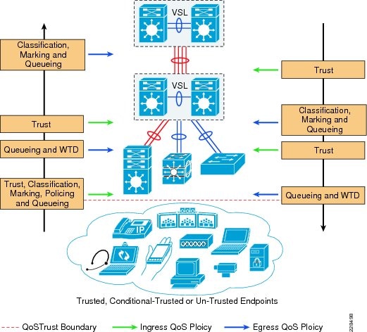
The trust or un-trust model simplifies the rules for defining bi-directional QoS policy settings. Figure 2 shows the QoS trust model setting that sets the QoS implementation guidelines in Borderless Campus networks.
Figure 2 Borderless Campus QoS Trust and Policies
Enterprise Campus QoS Overview
With an overall application strategy in place, end-to-end QoS policies can be designed for each device and interface, as determined by their roles in the network infrastructure. However, because the Cisco QoS toolset provides many QoS design and deployment options, a few succinct design principles can help simplify strategic QoS deployments, as discussed in the following sections.
Hardware versus Software QoS
A fundamental QoS design principle is, whenever possible, to enable QoS policies in hardware rather than software. Cisco IOS routers perform QoS in software, which places incremental loads on the CPU, depending on the complexity and functionality of the policy. Cisco Catalyst switches, on the other hand, perform QoS in dedicated hardware application-specific integrated circuits (ASICs) on Ethernet-based ports and as such do not tax their main CPUs to administer QoS policies. This allows complex policies to be applied at line rates even up to Gigabit or 10-Gigabit speeds.
Classification and Marking
When classifying and marking traffic, a recommended design principle is to classify and mark applications as close to their sources as technically and administratively feasible. This principle promotes end-to-end differentiated services and PHBs.
In general, it is not recommended to trust markings that can be set by users on their PCs or similar devices, because users can easily abuse provisioned QoS policies if permitted to mark their own traffic. For example, if an EF PHB has been provisioned over the network, a PC user can easily configure all their traffic to be marked to EF, thus hijacking network priority queues to service non-realtime traffic. Such abuse can easily ruin the service quality of realtime applications throughout the campus. On the other hand, if enterprise network administrator controls are in place that centrally administer PC QoS markings, it may be possible and advantageous to trust these.
Following this rule, it is recommended to use DSCP markings whenever possible, because these are end-to-end, more granular, and more extensible than Layer 2 markings. Layer 2 markings are lost when the media changes (such as a LAN-to-WAN/VPN edge). There is also less marking granularity at Layer 2. For example, 802.1P supports only three bits (values 0-7), as does Multiprotocol Label Switching Experimental (MPLS EXP). Therefore, only up to eight classes of traffic can be supported at Layer 2 and inter-class relative priority (such as RFC 2597 Assured Forwarding Drop Preference markdown) is not supported. Layer 3-based DSCP markings allow for up to 64 classes of traffic, which provides more flexibility and is adequate in large-scale deployments and for future requirements.
As the network border blurs between the borderless enterprise network and service providers, the need for interoperability and complementary QoS markings is critical. Cisco recommends following the IETF standards-based DSCP PHB markings to ensure interoperability and future expansion. Because enterprise voice, video, and data application marking recommendations are standards-based, as previously discussed, enterprises can easily adopt these markings to interface with service provider classes of service.
Policing and Markdown
There is little reason to forward unwanted traffic that gets policed and dropped by a subsequent tier node, especially when unwanted traffic is the result of DoS or worm attacks in the enterprise network. Excessive volume attack traffic can destabilize network systems, which can result in outages. Cisco recommends policing traffic flows as close to their sources as possible. This principle applies also to legitimate flows, because worm-generated traffic can masquerade under legitimate, well-known TCP/UDP ports and cause extreme amounts of traffic to be poured into the network infrastructure. Such excesses should be monitored at the source and marked down appropriately.
Whenever supported, markdown should be done according to standards-based rules, such as RFC 2597 (AF PHB). For example, excess traffic marked to AFx1 should be marked down to AFx2 (or AFx3 whenever dual-rate policing such as defined in RFC 2698 is supported). Following such markdowns, congestion management policies, such as DSCP-based WRED, should be configured to drop AFx3 more aggressively than AFx2, which in turn should be dropped more aggressively than AFx1.
Queuing and Dropping
Critical media applications require uncompromised performance and service guarantees regardless of network conditions. Enabling outbound queuing in each network tier provides end-to-end service guarantees during potential network congestion. This common principle applies to campus-to-WAN/Internet edges, where speed mismatches are most pronounced, and campus interswitch links, where oversubscription ratios create greater potential for network congestion.
Because each application class has unique service level requirements, each should optimally be assigned a dedicated queue. A wide range of platforms in varying roles exist in enterprise networks, so each must be bounded by a limited number of hardware or service provider queues. No fewer than four queues are required to support QoS policies for various types of applications, specifically:
- Realtime queue (to support a RFC 3246 EF PHB service)
- Guaranteed-bandwidth queue (to support RFC 2597 AF PHB services)
- Default queue (to support a RFC 2474 DF service)
- Bandwidth-constrained queue (to support a RFC 3662 scavenger service)
Additional queuing recommendations for these classes are discussed next.
Strict-Priority Queuing
The realtime or strict priority class corresponds to the RFC 3246 EF PHB. The amount of bandwidth assigned to the realtime queuing class is variable. However, if the majority of bandwidth is provisioned with strict priority queuing (which is effectively a FIFO queue), the overall effect is a dampening of QoS functionality, both for latency- and jitter-sensitive realtime applications (contending with each other within the FIFO priority queue) and also for non-realtime applications (because these may periodically receive significant bandwidth allocation fluctuations, depending on the instantaneous amount of traffic being serviced by the priority queue). Remember that the goal of convergence is to enable voice, video, and data applications to transparently co-exist on a single enterprise network infrastructure. When realtime applications dominate a link, non-realtime applications fluctuate significantly in their response times, destroying the transparency of the converged network.
For example, consider a 45 Mbps DS3 link configured to support two Cisco TelePresence CTS-3000 calls with an EF PHB service. Assuming that both systems are configured to support full high definition, each such call requires 15 Mbps of strict-priority queuing. Before the TelePresence calls are placed, non-realtime applications have access to 100 percent of the bandwidth on the link; to simplify the example, assume there are no other realtime applications on this link. However, after these TelePresence calls are established, all non-realtime applications are suddenly contending for less than 33 percent of the link. TCP windowing takes effect and many applications hang, timeout, or become stuck in a non-responsive state, which usually translates into users calling the IT help desk to complain about the network (which happens to be functioning properly, albeit in a poorly-configured manner).

Note![]() As previously discussed, Cisco IOS software allows the abstraction (and thus configuration) of multiple strict priority LLQs. In such a multiple LLQ context, this design principle applies to the sum of all LLQs to be within one-third of link capacity.
As previously discussed, Cisco IOS software allows the abstraction (and thus configuration) of multiple strict priority LLQs. In such a multiple LLQ context, this design principle applies to the sum of all LLQs to be within one-third of link capacity.
It is vitally important to understand that this strict priority queuing rule is simply a best practice design recommendation and is not a mandate. There may be cases where specific business objectives cannot be met while holding to this recommendation. In such cases, the enterprise network administrator must provision according to their detailed requirements and constraints. However, it is important to recognize the tradeoffs involved with over-provisioning strict priority traffic and its negative performance impact, both on other realtime flows and also on non-realtime-application response times.
And finally, any traffic assigned to a strict-priority queue should be governed by an admission control mechanism.
Best Effort Queuing
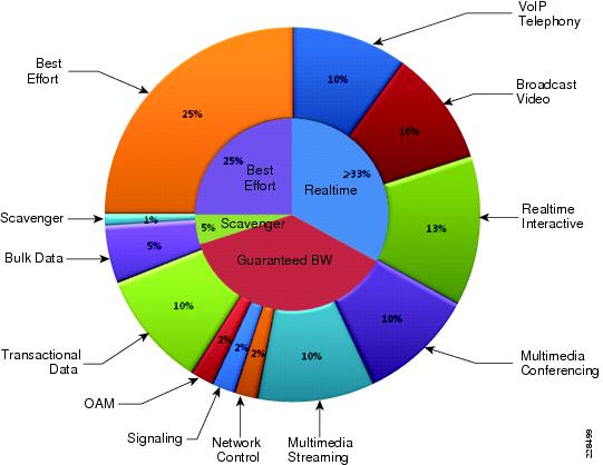
The best effort class is the default class for all traffic that has not been explicitly assigned to another application-class queue. Only if an application has been selected for preferential/deferential treatment is it removed from the default class. Because most enterprises may have several types of applications running in networks, adequate bandwidth must be provisioned for this class as a whole to handle the number and volume of applications that default to it. Therefore, Cisco recommends reserving at least 25 percent of link bandwidth for the default best effort class.
Scavenger Class Queuing
Whenever the scavenger queuing class is enabled, it should be assigned a minimal amount of link bandwidth capacity, such as 1 percent, or whatever minimal bandwidth allocation the platform supports. On some platforms, queuing distinctions between bulk data and scavenger traffic flows cannot be made, either because queuing assignments are determined by class of service (CoS) values (and both of these application classes share the same CoS value of 1) or because only a limited amount of hardware queues exist, precluding the use of separate dedicated queues for each of these two classes. In such cases, the scavenger/bulk queue can be assigned a moderate amount of bandwidth, such as 5 percent.
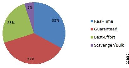
These queuing rules are summarized in Figure 3, where the inner pie chart represents a hardware or service provider queuing model that is limited to four queues and the outer pie chart represents a corresponding, more granular queuing model that is not bound by such constraints.
Figure 3 Compatible 4-Class and 12-Class Queuing Models
Deploying QoS in Borderless Campus Networks
All Layer 2 and Layer 3 systems in IP-based networks forward traffic based on best-effort, providing no differentiated services between different class-of-service network applications. The routing protocol forwards packets over the best low-metric or delay path, but offers no guarantee of delivery. This model works well for TCP-based data applications that adapt gracefully to variations in latency, jitter, and loss. The enterprise campus LAN and WAN is a multi-service network designed to support a wide range of low-latency voice and high bandwidth video with critical and non-critical data traffic over a single network infrastructure. For an optimal user experience, real time applications (such as voice and video) require packets to be delivered within specified loss, delay, and jitter parameters. Cisco QoS is a collection of features and hardware capabilities that allow the network to intelligently dedicate the network resources for higher priority real-time applications, while reserving sufficient network resources to service medium to lower non-real-time traffic. QoS accomplishes this by creating a more application-aware Layer 2 and Layer 3 network to provide differentiated services to network applications and traffic. For a detailed discussion of QoS, refer to the Enterprise QoS Design Guide at:
http://www.cisco.com/en/US/docs/solutions/Enterprise/WAN_and_MAN/QoS_SRND/QoS-SRND-Book.html
While the QoS design principles across the network are common, the QoS implementation in hardware- and software-based switching platforms vary due to internal system design. This section discusses the internal switching architecture and the differentiated QoS structure on a per-hop-basis.
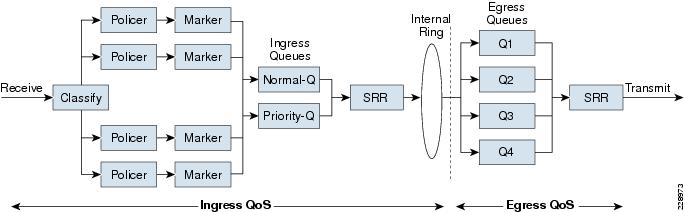
QoS in Cisco Catalyst Fixed Configuration Switches
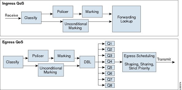
The QoS implementation in Cisco Catalyst 3560-X and 3750-X Series switches are similar. There is no difference in the ingress or egress packet classification, marking, queuing, and scheduling implementation among these Catalyst platforms. Cisco Catalyst switches allow users to create policy-maps by classifying incoming traffic (Layer 2 to Layer 4) and then attaching the policy-map to an individual physical port or to logical interfaces (SVI or port-channel). This creates a common QoS policy that may be used in multiple networks. To prevent switch fabric and egress physical port congestion, the ingress QoS policing structure can strictly filter excessive traffic at the network edge. All ingress traffic from edge ports passes through the switch fabric and moves to the egress ports, where congestion may occur. Congestion in access layer switches can be prevented by tuning queuing scheduler and Weighted Tail Drop (WTD) drop parameters. See Figure 1-4.
Figure 1-4 QoS Implementation in Cisco Catalyst Switches
The main difference between these platforms is the switching capacity, which ranges from 1G to 10G. The switching architecture and some of the internal QoS structure also differ. Some important differences to consider when selecting an access switch include:
QoS in Cisco Catalyst Modular Switches
The Cisco Catalyst 4500E and 6500-E are high-density, resilient switches for large scale networks. The Borderless Campus design uses both platforms across the network; therefore, all the QoS recommendations in this section for these platforms will remain consistent. Both next-generation Catalyst platforms are modular in design; however, there are significant internal hardware architecture differences between the two platforms that impact the QoS implementation model.
Catalyst 4500E QoS
The Cisco Catalyst 4500E Series platforms are widely deployed with classic and next-generation supervisors. This design guide recommends deploying the next-generation supervisor Sup7-E and the current-generation Sup6-E and Sup6L-E that offer a number of technical benefits that are beyond QoS.
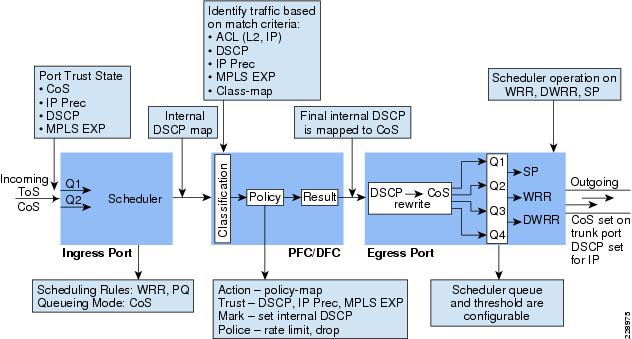
The Cisco Catalyst 4500E with Sup7-E, Sup-6E, and Sup6L-E (see Figure 5) is designed to offer better differentiated and preferential QoS services for various class-of-service traffic. New QoS capabilities in the Sup7-E, Sup-6E, and Sup6L-E enable administrators to take advantage of hardware-based intelligent classification and take action to optimize application performance and network availability. The QoS implementation in Sup7-E, Sup-6E, and Sup6L-E supports the Modular QoS CLI (MQC) as implemented in IOS-based routers that enhances QoS capabilities and eases implementation and operations. The following are some of the key QoS features that differentiate the next- and current- generation supervisor modules versus classic supervisors:
- Trust and Table-Map—MQC-based QoS implementation offers a number of implementation and operational benefits over classic supervisors that rely on the Trust model and internal Table-map as a tool to classify and mark ingress traffic.
- Internal DSCP—Unlike the classic supervisors that rely on the internal DSCP value, the queue placement in Sup7-E, Sup-6E, and Sup6L-E is simplified by leveraging the MQC capabilities to explicitly map any class of traffic (e.g., DSCP or CoS traffic) to an egress queue structure. For example, DSCP 46 can be classified with extended ACL and can be matched in PQ class-map of an MQC in Sup7-E, Sup-6E, and Sup6L-E.
- Sequential vs. Parallel Classification—With MQC-based QoS classification, the Sup7-E, Sup-6E, and Sup6L-E provide sequential classification rather than parallel. The sequential classification method allows network administrators to classify traffic at the egress based on the ingress markings.
Figure 5 Catalyst 4500E—Supervisor 7-E, Supervisor 6-E, and Supervisor 6L-E QoS Architecture
Catalyst 6500-E QoS
The Cisco Catalyst 6500-E Series are enterprise-class switches with next-generation hardware and software capabilities designed to deliver innovative, secure, converged borderless network services regardless of their place in the network. The Cisco Catalyst 6500-E can be deployed as a borderless service node in the campus network to offer a high performance, robust, and intelligent application and network awareness services. The Catalyst 6500-E provides leading-edge Layer 2-Layer 7 services, including rich high availability, manageability, virtualization, security, and QoS feature sets, as well as integrated Power-over-Ethernet (PoE), allowing for maximum flexibility in virtually any role within the campus.
Depending on the network services and application demands of the Cisco Catalyst 6500-E, the platform can be deployed with different types of Supervisor modules—Sup720-10GE, Sup720, and Sup32. This design guide uses the Sup720-10GE supervisor, which is built with next-generation hardware allowing administrators to build virtual network systems in a simplified and highly-redundant enterprise campus network. These supervisors leverage various featured daughter cards, including the Multilayer Switch Feature Card (MSFC) that serves as the routing engine, the Policy Feature Card (PFC) that serves as the primary QoS engine, as well as various Distributed Feature Cards (DFCs) that serve to scale policies and processing. Specifically relating to QoS, the PFC sends a copy of the QoS policies to the DFC to provide local support for the QoS policies, which enables the DFCs to support the same QoS features that the PFC supports. Since Cisco VSS is designed with a distributed forwarding architecture, the PFC and DFC functions are enabled and active on active and hot-standby virtual switch nodes and on distributed linecard modules. Figure 1-6 illustrates the internal PFC-based QoS architecture.
Figure 1-6 Cisco Catalyst 6500-E PFC QoS Architecture
Cisco Nexus 7000 QoS
The internal distributed system architecture of the Cisco Nexus 7000 differs from the modular Cisco Catalyst platforms. For the centralized management plane, users can build the campus core-class QoS policies for ingress and egress data traffic switching through the campus backbone switch. Applying the policy-map to a physical or logical interface programs the distributed forwarding engine on each I/O module to make the QoS policies effective in the system. The next-generation Cisco Nexus 7000 system supports MQC-based QoS policy configuration to build hierarchical classification and policy-maps to simplify the QoS operation at the core layer. By default QoS is enabled on Nexus 7000 system to perform the classification and queuing function based on ingress data traffic markings and internal mapping tables.
The Cisco Nexus 7000 system increases QoS performance with distributed and multi-stage QoS functions. To prevent congestion and prioritize real-time application traffic, such as VoIP and video, the QoS function is distributed between the port-asic, forwarding engine, and crossbar fabric path on the ingress and egress I/O modules. Each component performs a different level of inbound and outbound QoS policies to make effective switching decisions that minimize congestion for different class-of-service traffic. Each 10Gbps port of the recommended core-layer next-generation M108 I/O module is designed to perform at non-oversubscription and is equipped with a dual forwarding engine to load share the QoS function between two port groups. The M108 I/O module supports the ingress and egress Cos-to-Queue function to enable a 12-class campus QoS model for a broad range of network and data applications. Figure 1-7 illustrates the distributed Nexus 7000 QoS architecture with the recommended M108 10Gbps I/O module.
Figure 1-7 Cisco Nexus 7000 QoS Architecture

The Cisco Nexus 7000 system supports the following QoS class-map and policy configurations. Each method is designed to provide a different set of QoS functions in the system in different network environments:
- Queuing—The queuing class-map and policy-map enable the queuing and scheduling functions on the interface. The queuing class-maps are pre-defined in the Nexus 7000 system and the user cannot create a custom class-map for the ingress or egress queuing function. A user can customize the queuing policy-map and leverage the system-defined common queuing class-map to build the policy-map.
- QoS—Another set of class-maps and MQC policy-maps for the classification, marking, and policing functions. The user can customize the QoS class-map and policy-map to apply inbound and outbound policy-maps on the interfaces. The Nexus 7000 system provides the flexibility to apply two different QoS and queuing policy-maps on physical and logical interfaces.
- Network QoS—Network QoS defines common CoS characteristics across the Data Center Bridging (DCB) network, which is not currently applicable in campus network designs.
Deploying Access Layer QoS
The intelligent Cisco campus access layer switches provide the entry point to the network for various types of end devices managed by the enterprise IT department or employee’s personal devices (laptops, etc.). The secured access switch must decide whether to accept the QoS markings from each endpoint or whether to modify them. This is determined by the QoS policies and the trust model with which the endpoint is deployed.
QoS Trust Boundary
Network QoS policies need to be designed and implemented considering the entire borderless network. This includes defining trust points and determining which policies to enforce at each device within the network. Developing the trust model guides policy implementations for each device.
The devices (routers, switches, WLC) within the internal network boundary are managed by the system administrator and hence are classified as trusted devices. Access layer switches communicate with devices that are beyond the network boundary and within the internal network domain. The QoS trust boundary at the access layer communicates with various devices that could be deployed in different trust models (trusted, conditional-trusted, or untrusted). Figure 1-8 illustrates several types of devices in the network edge.
Figure 1-8 Borderless Campus QoS Trust Boundary
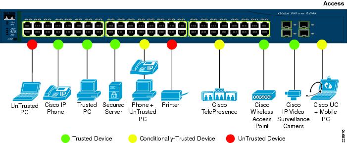
The enterprise network administrator must identify and classify each of these device types into one of three different trust models, each with its own unique security and QoS policies to access the network:
- Untrusted—An unmanaged device that does not pass through the network security policies, for example, an employee-owned PC or network printer. Packets with 802.1p or DSCP marking set by untrusted endpoints are reset to default by the access layer switch at the edge. Otherwise, it is possible for an unsecured user to consume network bandwidth that may impact network availability and security for other users.
- Trusted—Devices that passes through network access security policies and are managed by the network administrator. Even when these devices are maintained and secured by the network administrator, QoS policies must still be enforced to classify traffic and assign it to the appropriate queue to provide bandwidth assurance and proper treatment during network congestion.
- Conditionally-trusted—A single physical connection with one trusted endpoint and an indirect untrusted endpoint must be deployed as conditionally-trusted model. The trusted endpoints are still managed by the network administrator, but it is possible that the untrusted user behind the endpoint may or may not be secure (for example, a Cisco Unified IP phone and a PC). These deployment scenarios require a hybrid QoS policy that intelligently distinguishes and applies different QoS policies to the trusted and untrusted endpoints that are connected to the same port.
The ingress QoS policy at the access switches needs to be established, since this is the trust boundary where traffic enters the network. The following ingress QoS techniques are applied to provide appropriate service treatment and prevent network congestion:
- Trust—After classifying the endpoint the trust settings must be explicitly set by a network administrator. By default, Catalyst switches set each port in untrusted mode when QoS is enabled.
- Classification—An IETF standard has defined a set of application classes and provides recommended DSCP settings. This classification determines the priority the traffic will receive in the network. Using the IETF standard simplifies the classification process and improves application and network performance.
- Policing—To prevent network congestion, the access layer switch limits the amount of inbound traffic up to its maximum setting. Additional policing can be applied for known applications to ensure the bandwidth of an egress queue is not completely consumed by one application.
- Marking—Based on trust model, classification, and policer settings, the QoS marking is set at the edge before approved traffic enters through the access layer switching fabric. Marking traffic with the appropriate DSCP value is important to ensure traffic is mapped to the appropriate internal queue and treated with the appropriate priority.
- Queuing—To provide differentiated services internally in the Catalyst 29xx and 3xxx switching fabric, all approved traffic is queued into a priority or non-priority ingress queue. The ingress queuing architecture ensures real-time applications, like VoIP traffic, are given the appropriate priority (e.g., transmitted before data traffic).
Enabling QoS
By default, QoS is disabled on all Catalyst 3xxx Series switches and must be explicitly enabled in global configuration mode. The QoS configuration is the same for a multilayer or routed access deployment. The following sample QoS configuration must be enabled on all access layer switches deployed in the campus LAN network.
Access Layer 3xxx (Multilayer or Routed Access)
Note![]() The QoS function on the Catalyst 4500E with Sup7-E, Sup6-E, and Sup6L-E is enabled with the policy-map attached to the port and does not require any additional global configuration.
The QoS function on the Catalyst 4500E with Sup7-E, Sup6-E, and Sup6L-E is enabled with the policy-map attached to the port and does not require any additional global configuration.
Upon enabling QoS in the Catalyst switches, all physical ports are assigned untrusted mode. The network administrator must explicitly enable the trust settings on the physical port where trusted or conditionally trusted endpoints are connected. The Catalyst switches can trust the ingress packets based on 802.1P (CoS-based), ToS (ip-prec-based), or DSCP (DSCP-based) values. Best practice is to deploy DSCP-based trust mode on all the trusted and conditionally-trusted endpoints. This offers a higher level of classification and marking granularity than other methods. The following sample DSCP-based trust configuration must be enabled on the access switch ports connecting to trusted or conditionally-trusted endpoints.
QoS Trust Mode (Multilayer or Routed-Access)
Trusted Port
By default all the Sup7-E, Sup6-E, and Sup6L-E ports are in trusted mode; such a configuration leverages internal the DSCP mapping table to automatically classify QoS bit settings from incoming traffic and place it in the appropriate queue based on the mapping table. To set the appropriate network policy, the default settings must be modified by implementing ingress QoS policy-map. Refer to the “Implementing Ingress QoS Policing” section for further details.
Conditionally-Trusted Port
At the campus access layer the network edge port can be explicitly implemented to conditionally trust the port QoS setting based on end point, e.g., Cisco IP phone. When Trust Boundary is enabled as shown below, the edge port automatically becomes “untrusted” and the access layer switch marks the 802.1P CoS and DSCP values to 0 until the IP phone is detected on that port. QoS policies are applied according to these modified values.
UnTrusted Port
As described earlier, the default trust mode is untrusted when globally enabling the QoS function. Without explicit trust configuration on the Gi0/1 port, the following show command verifies current trust state and mode:
The QoS trust function on the Cisco Catalyst 4500E with Sup7-E, Sup6-E, and Sup6L-E is enabled by default and must be modified with the policy-map attached to the port.
Implementing Ingress QoS Classification
When creating QoS classification policies, the network administrator needs to consider what applications are present at the access edge (in the ingress direction) and whether these applications are sourced from trusted or untrusted endpoints. If PC endpoints are secured and centrally administered, then endpoint PCs may be considered trusted endpoints. In most deployments this is not the case, thus PCs are considered untrusted endpoints for the remainder of this document.
Not every application class, as defined in the Cisco-modified RFC 4594-based model, is present in the ingress direction at the access edge; therefore, it is not necessary to provision the following application classes at the access layer:
- Network Control—It is assumed that access layer switch will not transmit or receive network control traffic from endpoints; hence this class is not implemented.
- Broadcast Video—Broadcast video and a multimedia streaming server can be distributed across the campus network which may be broadcasting live video feed using multicast streams. These live video feed must be originated from the trusted distributed data center servers.
- Operation, Administration and Management—Primarily generated by network devices (routers and switches) and collected by management stations which are typically deployed in the trusted data center network or a network control center.
All applications present at the access edge need to be assigned a classification, as shown in Figure 9. Voice traffic is primarily sourced from Cisco IP telephony devices residing in the voice VLAN (VVLAN). These are trusted devices or conditionally trusted (if users also attach PCs, etc.) to the same port. Voice communication may also be sourced from PCs with soft-phone applications, like Cisco Unified Personal Communicator (CUPC). Since such applications share the same UDP port range as multimedia conferencing traffic (UDP/RTP ports 16384-32767), this soft-phone VoIP traffic is indistinguishable and should be classified with multimedia conferencing streams. See Figure 9.
Figure 9 Ingress QoS Application Model
Modular QoS MQC offers scalability and flexibility in configuring QoS to classify all 8-application classes by using match statements or an extended access list to match the exact value or range of Layer 4 known ports that each application uses to communicate on the network. The following sample configuration creates an extended access list for each application and then applies it under class-map configuration mode.
Creating class-map for each application services and applying match statement:
Implementing Ingress QoS Policing
It is important to limit how much bandwidth each class may use at the ingress to the access layer for two primary reasons:
- Bandwidth bottleneck—To prevent network congestion, each physical port at the trust boundary must be rate-limited. The rate-limit value may differ based on several factors—end-to-end network bandwidth capacity, end-station, and application performance capacities, etc.
- Bandwidth security—Well-known applications like Cisco IP telephony use a fixed amount of bandwidth per device based on a codec. It is important to police high-priority application traffic which is assigned to the high-priority queue, otherwise it could consume too much overall network bandwidth and impact other application performance.
In addition to policing, the rate-limit function also provides the ability to take different actions on the excess incoming traffic which exceeds the established limits. The exceed-action for each class must be carefully designed based on the nature of the application to provide best-effort services based on network bandwidth availability. Table 1 provides best practice policing guidelines for different classes to be implemented for trusted and conditional-trusted endpoints at the network edge.
|
|
|
|
|
<5Mbps 1 |
|||
|
1.The rate varies based on several factors as defined earlier. This table depicts a sample rate-limiting value. |
Catalyst 3xxx (Multilayer and Routed-Access)
Catalyst 4500E (Multilayer and Routed-Access)
All ingress traffic (default class) from untrusted endpoints must be policed without explicit classification that requires differentiated services. The following sample configuration shows how to deploy policing on untrusted ingress ports in access layer switches:
Implementing Ingress Marking
Accurate DSCP marking of ingress traffic at the access layer switch is critical to ensure proper QoS service treatment as traffic traverses through the network. All classified and policed traffic must be explicitly marked using the policy-map configuration based on an 8-class QoS model as shown in Figure 14.
Best practice is to use a explicit marking command (set dscp) even for trusted application classes (like VVLAN-VOIP and VVLAN-SIGNALING), rather than a trust policy-map action. A trust statement in a policy map requires multiple hardware entries with the use of an explicit (seemingly redundant) marking command and improves hardware efficiency.
The following sample configuration shows how to implement explicit marking for multiple classes on trusted and conditionally-trusted ingress ports in access layer switches:
Trusted or Conditionally-Trusted Port
All ingress traffic (default class) from an untrusted endpoint must be marked without a explicit classification. The following sample configuration shows how to implement explicit DSCP marking:
Untrusted Port
Applying Ingress Policies
After creating a policy-map on all the Layer 2 and Layer 3 access switches with QoS policies defined, the service-policy must be applied on the edge interface of the access layer to enforce the QoS configuration. Cisco Catalyst switches offer three simplified methods to apply service-policies; depending on the deployment model any of the methods can be implemented:
- Port-Based QoS—Applying the service-policy on a per-physical-port basis forces traffic to pass through the QoS policies before entering into the campus network. Port-Based QoS discretely functions on a per-physical port basis even if it is associated with a logical VLAN which is applied on multiple physical ports.
- VLAN-Based QoS—Applying the service-policy on a per-VLAN basis requires the policy-map to be attached to a VLAN. Every physical port associated to a VLAN that requires bandwidth guarantee or traffic shaping needs extra configuration at the interface level.
- Per-Port / Per-VLAN-Based QoS—This is not supported on all Catalyst platforms and the configuration commands are platform-specific. Per-port/per-VLAN-based QoS allows policy-map to operate on a trunk interface. A different policy-map can be applied to specific VLANs within a trunk interface.
See Figure 10.
Figure 10 QoS Policies Implementation Methods

The following sample configuration provides guidelines to deploy port-based QoS on the access layer switches in the campus network:
Applying Ingress Queuing
Fixed configuration Cisco Catalyst switches not only offer differentiated services on the network ports, but also internally on the switching fabric. After enabling QoS and attaching inbound policies on the physical ports, all the packets that meet the specified policy are forwarded to the switching fabric for egress switching. The aggregate bandwidth from all edge ports may exceed the switching fabric bandwidth and cause internal congestion.
Cisco Catalyst 3xxx platforms support two internal ingress queues—normal queue and priority queue. The ingress queue inspects the DSCP value on each incoming frame and assigns it to either the normal or priority queue. High priority traffic, like DSCP EF marked packets, are placed in the priority queue and switched before processing the normal queue.
The Catalyst 3750-X family of switches supports the weighted tail drop (WTD) congestion avoidance mechanism. WTD is implemented on queues to manage the queue length. WTD drops packets from the queue based on DSCP value and the associated threshold. If the threshold is exceeded for a given internal DSCP value, the switch drops the packet. Each queue has three threshold values. The internal DSCP determines which of the three threshold values is applied to the frame. Two of the three thresholds are configurable (explicit) and one is not (implicit). This last threshold corresponds to the tail of the queue (100 percent limit).
Figure 11 depicts how different class-of-service applications are mapped to the ingress queue structure (1P1Q3T) and how each queue is assigned a different WTD threshold.
Figure 11 Catalyst 3xxx DSCP-based Ingress QoS Model

Note![]() The ingress queuing function on the Catalyst 4500E Sup7-E, Sup6-E, and Sup6L-E is not supported as described in Figure 5.
The ingress queuing function on the Catalyst 4500E Sup7-E, Sup6-E, and Sup6L-E is not supported as described in Figure 5.
Implementing Access Layer Egress QoS
The QoS implementation of egress traffic towards network edge devices on access layer switches is much simplified compared to ingress traffic which requires stringent QoS policies to provide differentiated services and network bandwidth protection. Unlike the ingress QoS model, the egress QoS model must provide optimal queuing policies for each class and set the drop thresholds to prevent network congestion and degraded application performance. With egress queuing in DSCP mode, the Cisco Catalyst switching platforms are bounded by a limited number of hardware queues.
Catalyst 3xxx Egress QoS
The Cisco Catalyst 3xxx Series platform supports four egress queues that are required to support the variable class QoS policies for the enterprise campus network; specifically, the following queues would be considered a minimum:
- Realtime queue (to support a RFC 3246 EF PHB service)
- Guaranteed bandwidth queue (to support RFC 2597 AF PHB services)
- Default queue (to support a RFC 2474 DF service)
- Bandwidth constrained queue (to support a RFC 3662 scavenger service)
As a best practice, each physical or logical interface must be deployed with IETF recommended bandwidth allocations for different class-of-service applications:
- The real-time queue should not exceed 33 percent of the link’s bandwidth.
- The default queue should be at least 25 percent of the link’s bandwidth.
- The bulk/scavenger queue should not exceed 5 percent of the link’s bandwidth.
Figure 12 illustrates the egress bandwidth allocation best practices design for different classes.
Figure 12 Class-of-Service Egress Bandwidth Allocations
Given these minimum queuing requirements and bandwidth allocation recommendations, the following application classes can be mapped to the respective queues:
- Realtime Queue—Voice, broadcast video, and realtime interactive may be mapped to the realtime queue (per RFC 4594).
- Guaranteed Queue—Network/internetwork control, signaling, network management, multimedia conferencing, multimedia streaming, and transactional data can be mapped to the guaranteed bandwidth queue. Congestion avoidance mechanisms (i.e., selective dropping tools), such as WRED, can be enabled on this class; furthermore, if configurable drop thresholds are supported on the platform, these may be enabled to provide intra-queue QoS to these application classes in the respective order they are listed (such that control plane protocols receive the highest level of QoS within a given queue).
- Scavenger/Bulk Queue—Bulk data and scavenger traffic can be mapped to the bandwidth-constrained queue and congestion avoidance mechanisms can be enabled on this class. If configurable drop thresholds are supported on the platform, these may be enabled to provide inter-queue QoS to drop scavenger traffic ahead of bulk data.
- Default Queue—Best-effort traffic can be mapped to the default queue; congestion avoidance mechanisms can be enabled on this class.
Like the ingress queuing structure that maps various applications based on DSCP value into two ingress queues, the egress queuing must be similarly designed to map with four egress queues. The DSCP-to-queue mapping for egress queuing must be mapped to each egress queue as stated above, which allows better queuing-policy granularity. A campus egress QoS model example for a platform that supports DSCP-to-queue mapping with a 1P3Q3T queuing structure is depicted in Figure 13.
Figure 13 Catalyst 3xxx DSCP-based 1P3Q3T Egress QoS Model
DSCP marked packets are assigned to the appropriate queue and each queue is configured with appropriate WTD threshold as defined in Figure 13. Egress queuing settings are common between all the trust-independent network edge ports as well as on the Layer 2 or Layer 3 uplinks connected to the internal network. The following egress queue configuration entered in global configuration mode must be enabled on every access layer switch in the network.
Catalyst 3xxx (Multilayer and Routed-Access)
Catalyst 4500E Sup7-E, Sup6-E, and Sup6L-E Egress QoS
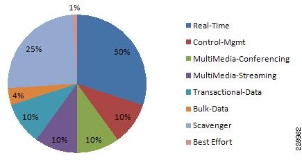
The enterprise-class 4500E switch with next-generation supervisor hardware architecture is designed to offer better egress QoS techniques, capabilities, and flexibility to provide for a well-diversified queuing structure for multiple class-of-service traffic types. Deploying the next-generation Sup7-E, Sup6-E, and Sup6L-E in the campus network provides more QoS granularity to map the 8-class traffic types to hardware-based egress-queues as illustrated in Figure 14.
Figure 14 Eight Class-of-Service Egress Bandwidth Allocations
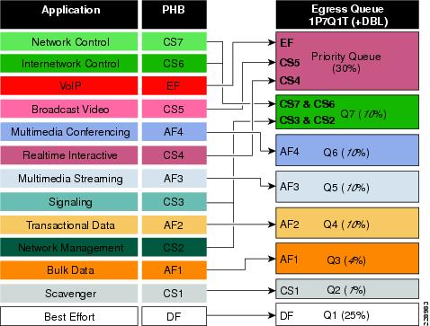
The Cisco Catalyst 4500E Sup7-E, Sup6-E, and Sup6L-E supervisors support platform-specific congestion avoidance algorithms to provide Active Queue Management (AQM), namely Dynamic Buffer Limiting (DBL). DBL is flow-based and uses logical flow tables per port/per queue for each port. It operates by tracking the amount of buffering and credits for each flow currently active in that queue. When the queue length of a flow exceeds its limit, DBL drops packets or sets the Explicit Congestion Notification (ECN) bits in the TCP packet headers. With 8 egress (1P7Q1T) queues and DBL capability in the Sup7-E- and Sup6-E-based supervisors, the bandwidth distribution for different classes change. Figure 15 provides the new recommended bandwidth allocation.
Figure 15 Catalyst 4500E DSCP-based 1P7Q1T Egress QoS Model
The QoS architecture and implementation procedures are identical among the Sup7-E, Sup6-E, and Sup6L-E modules. Implementing QoS policies on a Sup7-E-based Catalyst 4500E platform follows the IOS (MQC)-based configuration model instead of the Catalyst OS-based QoS model. To take advantage of hardware-based QoS egress, the queuing function using MQC must be applied per member-link of the EtherChannel interface. Therefore, load-sharing egress per-flow traffic across EtherChannel links offers the advantage of optimally using distributed hardware resources.
The recommended DSCP markings for each traffic class can be classified in a different class-map for egress QoS functions. Based on Figure 15, the following configuration uses the new egress policy-map with queuing and the DBL function implemented on the Catalyst 4500E deployed with a Sup7-E, Sup6-E, and Sup6L-E supervisor module. All network edge port and core-facing uplink ports must use a common egress policy-map.
Policing Priority-Queue
EtherChannel is an aggregated logical bundle of interfaces that do not perform queuing and rely on individual member links to queue egress traffic by using hardware-based queuing. The hardware-based priority-queue implementation on the Catalyst 4500E does not support a built-in policer to restrict traffic during network congestion. To mitigate this challenge, it is recommended to implement an additional policy-map to rate-limit the priority class traffic and the policy-map must be attached on the EtherChannel to govern the aggregated egress traffic limits. The following additional policy-map must be created to classify priority-queue class traffic and rate-limit up to 30 percent egress link capacity:
|
|
|
|
|
|
|
|
|
|
|
|
|
|
|
|
Deploying Network-Layer QoS
Borderless Campus network systems at the large campus and remote medium and small campus are managed and maintained by the enterprise IT administration to provide key network foundation services such as routing, switching, QoS, and virtualization. In a best practice network environment, these systems must be implemented with the recommended configurations to provide differentiated borderless network services on a per-hop basis. To allow for consistent application delivery throughout the network, it is recommended to implement bidirectional QoS policies on distribution and core layer systems.
QoS Trust Boundary
All enterprise IT managed campus LAN and WAN network systems can be classified as trusted devices and must follow the same QoS best practices recommended in a previous subsection. It is recommended to avoid deploying trusted or untrusted endpoints directly to the campus distribution and core layer systems.
Based on the global network QoS policy, each class-of-service application receives the same treatment. Independent of the enterprise network tier—LAN/WAN, platform type, and their capabilities— each device in the network protects service quality and enables communication across the network without degrading application performance.
Implementing Network-Layer Ingress QoS
As described earlier, the internal campus core network must be considered to be trusted. The next-generation Cisco Catalyst access layer platform must be deployed with more application-aware and intelligence at the network edge. The campus core and distribution network devices should rely on the access layer switches to implement QoS classification and marking based on a wide-range of applications and IP-based devices deployed at the network edge.
To provide consistent and differentiated QoS services on per-hop basis across the network, the distribution and core network must be deployed to trust incoming pre-marked DSCP traffic from the downstream Layer 2 or Layer 3 network devices. This Borderless Campus network design recommends deploying a broad range of Layer 3 Catalyst switching platforms in the campus distribution layer and Catalyst 6500-E VSS and Nexus 7000 in the core layer. As mentioned in the previous section, the hardware architecture of each switching platform is different, based on the platform capabilities and resources. This changes how the different class-of-service traffic types are handled in different directions—ingress, switching fabric, and egress.
Cisco Catalyst access layer switches must classify the application and device type to mark DSCP value based on the trust model with deep packet inspection using access lists (ACL) or protocol-based device discovery. Therefore there is no need to reclassify the same class-of-service at the campus distribution and core layers. The campus distribution and core layers can trust DSCP markings from the access layer and provide QoS transparency without modifying the original parameters unless the network is congested.
Based on the simplified internal network trust model, the ingress QoS configuration also becomes more simplified and manageable. This subsection provides common ingress QoS deployment guidelines for the campus distribution and core for all locations:
QoS Trust Mode
As described earlier, the QoS function in the Cisco Nexus 7000 system is trusted and enabled by default. The Nexus 7000 system automatically performs the ingress and egress classification and queuing QoS function with default Cos-to-Queue map settings. The network data traffic is automatically placed in ingress and egress queues based on marking done at the campus access layer to appropriately utilize port bandwidth resources. In the default configuration setting, the Cisco Nexus 7000 protects the original DSCP markings performed by the end-point or an access layer switch.
The Catalyst 4500E deployed with either a Sup7-E, Sup6-E, or Sup6L-E supervisor module in the distribution or in the collapsed core layer automatically sets the physical ports in the trust mode. The Catalyst 4500E by default performs DSCP-CoS or CoS-DSCP mappings to transmit traffic transparently without any QoS bits rewrites. However the default QoS function on campus distribution or core platforms like the 6500-E Series switches is disabled.
When QoS trust is disabled by default, the network administrator must manually enable QoS globally on the switch and explicitly enable DSCP trust mode on each logical EtherChannel and each member link interface connected to upstream and downstream devices. The distribution layer QoS trust configuration is the same for a multilayer or routed-access deployment. The following sample QoS configuration must be enabled on all the distribution and core layer switches deployed in a campus LAN network.
Distribution and Core Layer 6500-E
This document characterized the Cisco Nexus 7000 running the Cisco NX-OS 5.1.3 software version which currently supports a CoS-based trust model and does not support a DSCP-based model for ingress or egress network traffic. The incoming pre-marked DSCP data traffic is automatically classified and appropriately queued based on the internal system CoS-to-DSCP mapping table.
Applying Ingress Queuing
The Catalyst 6500-E and Nexus 7000 system support the ingress queuing function to classify ingress traffic and place it in the ingress queue for ingress scheduling and data prioritization prior to forwarding data traffic to the switch fabric. Implementing the ingress queuing function is effective when the high-speed ports on the network module operate at an over-subscription rate. In a non-oversubscription network module, the ingress queuing provides data prioritization and protection if internal fabric backplane bandwidth is reduced, creating internal forwarding congestion.
The Cisco Catalyst 4500E deployed with a Sup7-E, Sup6-E, or a Sup6L-E supervisor module does not support ingress queuing.
Implementing Catalyst 6500-E Ingress Queuing
When 6500-E switching platforms receive various class-of-service requests from different physical ports, then depending on the DSCP and CoS markings, they can queue the traffic prior sending it to the switching fabric in a FIFO manner. There are two main considerations relevant to ingress queuing design on the Catalyst 6500-E:
- The degree of oversubscription (if any) of the linecard
- Whether the linecard requires trust-CoS to be enabled to engage ingress queuing
Some linecards may be designed to support a degree of oversubscription that theoretically offers more traffic to the linecard than the sum of all GE/10GE switch ports than can collectively access the switching backplane at once. Since such a scenario is extremely unlikely, it is often more cost-effective to use linecards that have a degree of oversubscription within the campus network. However, if this design choice has been made, it is important for network administrators to recognize the potential for drops due to oversubscribed linecard architectures. To manage application class service levels during such extreme scenarios, ingress queuing models may be enabled.
While the presence of oversubscribed linecard architectures may be viewed as the sole consideration in enabling or not enabling ingress queuing, a second important consideration is that many Catalyst 6500-E linecards only support CoS-based ingress queuing models that reduce classification and marking granularity—limiting the administrator to an 8-class 802.1Q/p model. Once CoS is trusted, DSCP values are overwritten (via the CoS-to-DSCP mapping table) and application classes sharing the same CoS values are longer distinguishable from one another. Therefore, given this classification and marking limitation and the fact that the value of enabling ingress queuing is only achieved in extremely rare scenarios, it is not recommended to enable CoS-based ingress queuing on the Catalyst 6500-E. Rather, limit such linecards and deploy either non-oversubscribed linecards and/or linecards supporting DSCP-based queuing at the distribution and core layers of the campus network.
Table 1 summarizes recommended linecards by listing and oversubscription ratios and whether the ingress queuing models are CoS- or DSCP-based.
Note![]() The Catalyst WS-X6716-10GE can be configured to operate in Performance Mode (with an 8Q4T ingress queuing structure) or in Oversubscription Mode (with a 1P7Q2T ingress queuing structure). In Performance mode, only one port in every group of four is operational (while the rest are administratively shut down), which eliminates any oversubscription on this linecard and as such ingress queuing is not required (as only 4 x 10GE ports are active in this mode and the backplane access rate is also at 40 Gbps). In Oversubscription Mode (the default mode), all ports are operational and the maximum oversubscription ratio is 4:1. Therefore, it is recommended to enable 1P7Q2T DSCP-based ingress queuing on this linecard in Oversubscription Mode.
The Catalyst WS-X6716-10GE can be configured to operate in Performance Mode (with an 8Q4T ingress queuing structure) or in Oversubscription Mode (with a 1P7Q2T ingress queuing structure). In Performance mode, only one port in every group of four is operational (while the rest are administratively shut down), which eliminates any oversubscription on this linecard and as such ingress queuing is not required (as only 4 x 10GE ports are active in this mode and the backplane access rate is also at 40 Gbps). In Oversubscription Mode (the default mode), all ports are operational and the maximum oversubscription ratio is 4:1. Therefore, it is recommended to enable 1P7Q2T DSCP-based ingress queuing on this linecard in Oversubscription Mode.
Additional details on these WS-X6716-10GE operational modes can be found at: http://www.cisco.com/en/US/prod/collateral/switches/ps5718/ps708/qa_cisco_catalyst_6500_series_16port_10gigabit_ethernet_module.html
If 6708 and 6716 linecards (with the latter operating in oversubscription mode) are used in the distribution and core layers of the campus network, then 8Q4T DSCP-based ingress queuing and 1P7Q2T DSCP-based ingress queuing (respectively) are recommended to be enabled. These queuing models are detailed in the following sections.
Figure 16 depicts how different class-of-service applications are mapped to the ingress queue structure (8Q4T) and how each queue is assigned a different WTD threshold.
Figure 16 Catalyst 6500-E Ingress Queuing Model
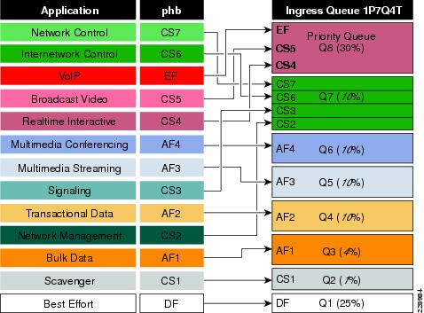
The corresponding configuration for 8Q8T (DSCP-to-Queue) ingress queuing on a Catalyst 6500-E VSS in the distribution and core layers is shown below. The PFC function is active on active and hot-standby virtual-switch nodes; therefore, ingress queuing must be configured on each distributed member link of Layer 2 or Layer 3 MEC.
Implementing Cisco Nexus 7000 Ingress Queuing
The Nexus 7000 system supports ingress queuing on all M1 series I/O modules, however implementing the ingress queuing policy is different in the Nexus 7000 system. The NX-OS supports pre-defined multiple ingress queuing class-maps for different models—8Q2T and 2Q4T. Based on the ingress queue capability of the I/O module, the network administrator can create an ingress queue policy-map and leverage system-defined ingress queuing class-maps to classifying CoS value for each queue. The ingress queue policies are by default attached to every physical port of the Nexus 7000 system and are always in effect until new user-defined QoS policies are applied to the port to override the default configuration. The default ingress class-map names cannot be modified or removed, however the NX-OS provides the flexibility to remap default CoS-to-Queue as needed.
The Cisco Nexus 7000 supports 8 port 10Gbps M108 and 32 port 10Gbps M132 series I/O modules with advanced Layer 3 campus core layer technologies. Both modules operate at 10Gbps and provide up to 80Gbps backplane switching capacity. However these modules are designed to be deployed in a specific network layer to provide the appropriate level port scalability and switching performance. The M108 is a high-performance I/O module designed to be deployed in the high-speed campus and data center core layer. This module provides wire-speed throughput and distributed services, such as QoS and ACL, through a dual-forwarding engine attached to a single M108 module. The M132 I/O module is commonly deployed in a high-density aggregation layer to interconnect access layer switches through high-speed 10Gbps links.
The default port bandwidth and resource allocation settings for each physical port differ on both module types. Table 1 summarizes the ingress QoS comparison between both Nexus 7000 M1 series I/O modules.
|
|
|
|
|
|
|
|
| (2 x Crossbar Fabric)3 |
||||||
| (8 x 10GE ports)4 |
Figure 17 illustrates how different class-of-service applications are mapped to the ingress queue structure (8Q2T) and how each queue is assigned a different bandwidth and WTD threshold.
Figure 17 Nexus 7000 CoS-Based 8Q2T Ingress QoS Model

For each ingress queue model, the NX-OS currently supports, system-wide, a single set of ingress queue class-maps (for example, a single CoS classification rule for each ingress queue). In a best practice campus network design, the network administrator should follow the recommendation to implement ingress policy based on a 12-class QoS model. Such a QoS design provides consistent QoS treatment on a hop-by-hop basis in a campus network.
As described previously, the Cisco Nexus 7000 system supports a default system-defined ingress queuing and the default policy-map is attached by default to each physical port of the system. The default ingress queuing policy by default uses the first queue and the default or last queue. The default settings can be verified with the show policy-map command. as illustrated below:
The default class-map may vary based on the type of linecard used. The system default in-q1 class-map is general class-map for the module that supports 8Q2T or 2Q4T. Since the M108 module supports a 8Q2T ingress queuing model, the network administrator may verify default CoS-to-Queue settings based on 8q2t-in.
The system-defined default ingress bandwidth allocation, queue-limit, and drop threshold parameters are also different than the recommended ingress QoS model as illustrated in Figure 17.
As described previously, the system-defined ingress queue QoS policy is active and operational with bandwidth and thresholds for ingress queue 1 and ingress queue 8 class-maps. By default no CoS bits are mapped or bandwidth assigned to the remaining ingress queues, hence these queues are not utilized and remain un-used. If the network administrator modifies the system-defined default queuing policy-maps without following implementation best practices, the campus core layer network may experience instability that can cause severe service disruption.
Modifying the default class-map configuration by re-mapping CoS values to un-used class-maps may result in insufficient bandwidth for internal processing. Due to such mis-configuration and lack of internal bandwidth, network control traffic may be impacted and de-stabilize the entire network topology.
Note![]() It is highly recommended to follow best practices to seamlessly enable ingress queuing policy on the Cisco Nexus 7000 system. The network administrator must follow the exact steps described below to implement ingress queuing policy.
It is highly recommended to follow best practices to seamlessly enable ingress queuing policy on the Cisco Nexus 7000 system. The network administrator must follow the exact steps described below to implement ingress queuing policy.
Step 1![]() Create the ingress queue policy-map. To utilize all ingress queues for a 12-class QoS model, the policy-map should have all 8Q2T class-maps assigned in this policy. On a per-class basis, apply the recommended bandwidth, queue-limit, and WRED parameters as required for ingress class-map:
Create the ingress queue policy-map. To utilize all ingress queues for a 12-class QoS model, the policy-map should have all 8Q2T class-maps assigned in this policy. On a per-class basis, apply the recommended bandwidth, queue-limit, and WRED parameters as required for ingress class-map:
Step 2![]() Attach the ingress queuing policy-map to a physical Layer 3 interface or to a logical port channel interface in an EtherChannel-based network design. The QoS policy automatically becomes effective on each member link of EtherChannel once attached to a port-channel interface:
Attach the ingress queuing policy-map to a physical Layer 3 interface or to a logical port channel interface in an EtherChannel-based network design. The QoS policy automatically becomes effective on each member link of EtherChannel once attached to a port-channel interface:
Step 3![]() Once the ingress queue policy-map is created and bandwidth and queue-limit are allocated to each class, the default CoS-to-Queue can be safely re-mapped across each ingress queue class-map that was created in Step 1. To utilize each ingress queue, the network administrator must assign a single CoS value to enable one queue per class configuration:
Once the ingress queue policy-map is created and bandwidth and queue-limit are allocated to each class, the default CoS-to-Queue can be safely re-mapped across each ingress queue class-map that was created in Step 1. To utilize each ingress queue, the network administrator must assign a single CoS value to enable one queue per class configuration:
Implementing Network Core Egress QoS
The QoS implementation of egress traffic towards network edge devices on access layer switches are much simplified compared to ingress traffic, which requires stringent QoS policies to provide differentiated services and network bandwidth protection. Unlike the ingress QoS model, the egress QoS model must provide optimal queuing policies for each class and sets the drop thresholds to prevent network congestion and an impact to application performance. With egress queuing in DSCP mode, the Cisco Catalyst switching platforms and linecards are bounded by a limited number of egress hardware queues.
Catalyst 4500E
The configuration and implementation guidelines for egress QoS on the Catalyst 4500E with Sup7-E, Sup6-E, or Sup6L-E in distribution and access layer roles remains consistent. All conformed traffic marked with DSCP values must be manually assigned to each egress queue based on a four class-of-service QoS model. Refer to the “Implementing Access Layer Egress QoS” section for the deployment details.
Catalyst 6500-E—VSS
The Cisco Catalyst 6500-E in VSS mode operates in a centralized management mode, but uses a distributed forwarding architecture. The Policy Feature Card (PFC) on active and hot-standby is functional on both nodes and is independent of the virtual switch role. Like ingress queuing, the network administrator must implement egress queuing on each of the member links of the Layer 2 or Layer 3 MEC. The egress queuing model on the Catalyst 6500-E is based on linecard type and its capabilities; when deploying Catalyst 6500-E in VSS mode only, the WS-67xx series 1G/10G linecard with daughter card CFC or DFC3C/DFC3CXL is supported.
Table 1 describes the deployment guidelines for the Catalyst 6500-E Series linecard module in the campus distribution and core layer network. In the solutions lab, WS-6724-SFP and WS-6708-10GE were validated in the campus distribution and core layers. As both modules support different egress queuing models, this subsection provides deployment guidelines for both module types.
|
|
|
|
|
|
|
198 MB5 91 MB6 |
|
|
WS-6724-SFP—1P3Q8T Egress Queuing Model
On the WS-6724-SFP module the egress queuing functions on a per-physical-port basis and independent of link layer and above protocols settings; these functions remain consistent when the physical port is deployed in standalone or bundled into an EtherChannel. Each 1G physical port supports four egress queues with the default CoS based on the transmit side. This module is a cost-effective, 1G, non-blocking, high-speed network module, but does not provide deep application granularity based on different DSCP markings. It does not have the flexibility to use various class-of-service egress queues for applications. Campus LAN QoS consolidation to a four class model occurs on the physical paths that connect to the WAN or Internet edge routers, which forward traffic across a private WAN or the Internet. Deploying the WS-6724-SFP module in a four class model would be recommended in that design. Figure 18 illustrates 1P3Q8T egress queuing model to be applied on the Catalyst 6500-E – WS-6724-SF module.
Figure 18 Catalyst 6500-E CoS-based 1P3Q8T Egress QoS Model
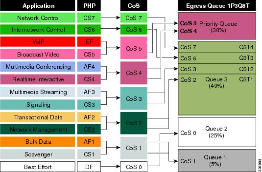
The following corresponding 1P3Q8T egress queuing configuration must be applied on each member link of MEC.
WS-6708-10GE and WS-6716-10GE—1P7Q4T Egress Queuing Model
The hardware design of the next-generation 10G linecards are designed with advanced ASICs and higher capacity to ensure the campus backbone of large enterprise networks are ready for the future. Both modules support DSCP based on the eight queue model to deploy flexible and scalable QoS in the campus core. With 8-egress queue support the WS-6708-10G and WS-6716-10G modules increased application granularity based on various DSCP markings done at the network edge. Figure 19 illustrates the DSCP-based 1P7Q4T egress queuing model.
Figure 19 Catalyst 6500-E DSCP-based P7Q4T Egress QoS Model

The following corresponding 1P7Q4T egress queuing configuration must be applied on each member link of MEC.
Note![]() Due to the default WRED threshold settings, at times the maximum threshold needs to be configured before the minimum (as is the case on queues one through three in the example above); at other times, the minimum threshold needs to be configured before the maximum (as is the case on queues four through seven in the example above).
Due to the default WRED threshold settings, at times the maximum threshold needs to be configured before the minimum (as is the case on queues one through three in the example above); at other times, the minimum threshold needs to be configured before the maximum (as is the case on queues four through seven in the example above).
Implementing Cisco Nexus 7000 Egress Queuing
The egress queuing function on the Cisco Nexus 7000 is performed on the forwarding engine and port-asic of an egress I/O module. The forwarding engine performs the CoS classification, remarking, and policing whereas the port-asic provides performs the egress scheduling and queuing function. The recommended M108 I/O module supports 1P7Q4T queue support on a per-port level.
Like ingress queuing, the egress queuing function is enabled by default in Cisco Nexus 7000 switches. The system-defined egress class-map and policy-map are by default attached to each physical interface of the system to automatically perform outbound QoS functions. The system-defined default egress queuing policy-map is applied on the low-speed I/O module that supports reduced 1P3Q4T queue capacity. Hence the default egress queue configuration must be fine tuned for the M108 I/O module that supports 1P7Q4T queuing model. The CoS-based egress queue mode is enabled by default, however to align with the recommended 12-class QoS model in a campus design, the network administrator must modify the default CoS-to-Queue mapping table to use a single queue for each class-of-service application traffic. Figure 20 illustrates the recommended 1P7Q4T egress queuing model on the Nexus 7000 system.
Figure 20 Nexus 7000 CoS-Based 1P7Q4T Egress QoS Model

To enable egress QoS on a Cisco Nexus 7000 platform, perform the following steps:
Step 1![]() The network administrator must first create a custom queuing type policy-map. To utilize each egress queue, the system-defined egress queuing class-map must be used to assign bandwidth, queue limit, and WRED threshold for different class-of-service applications and network data traffic.
The network administrator must first create a custom queuing type policy-map. To utilize each egress queue, the system-defined egress queuing class-map must be used to assign bandwidth, queue limit, and WRED threshold for different class-of-service applications and network data traffic.
Step 2![]() Modify the default egress CoS-to-Queue mapping to align with the recommended CoS setting as illustrated in Figure 20:
Modify the default egress CoS-to-Queue mapping to align with the recommended CoS setting as illustrated in Figure 20:
Once the policy-map is configured on the system, the network administrator can apply the egress policy-map on each physical and logical port-channel interface. The policy-map applied on a logical port-channel is automatically applied on each member link interface.
Summary
As enterprise customers expand their applications onto their campus networks, ensuring the right amount of bandwidth and prioritization of traffic is essential. This chapter provides an overview of QoS and recommendations and best practices for all switches in the Borderless Campus 1.0 architecture.
 Feedback