SD-Routing Migration Guide
Available Languages
Bias-Free Language
The documentation set for this product strives to use bias-free language. For the purposes of this documentation set, bias-free is defined as language that does not imply discrimination based on age, disability, gender, racial identity, ethnic identity, sexual orientation, socioeconomic status, and intersectionality. Exceptions may be present in the documentation due to language that is hardcoded in the user interfaces of the product software, language used based on RFP documentation, or language that is used by a referenced third-party product. Learn more about how Cisco is using Inclusive Language.
- US/Canada 800-553-2447
- Worldwide Support Phone Numbers
- All Tools
 Feedback
 Feedback
This document describes on the introduction to Cisco SD-Routing (Software-defined Routing) and the migration of legacy Overlay deployments like DMVPN from traditional routing to SD-Routing. The traditional routing to SD-Routing migration involves multiple steps in a phased manner.
Cisco SD-Routing simplifies traditional routing deployment with agile workflows for device lifecycle orchestration, monitoring, and troubleshooting.
Why Migrate to SD-Routing
Cisco SD-Routing provides intuitive device lifecycle orchestration workflows for secure device onboarding and software upgrades. Leveraging the rich monitoring and troubleshooting capabilities of Cisco Catalyst SD-WAN Manager, administrators can quickly isolate and resolve network problems. With Cisco IOS XE 17.12.1, customers can manage their routing devices in a flexible manner through on-premises controllers. Cisco SD-Routing will also be offered through cloud-delivered controllers soon.
Table 1. Table 1. SD-Routing Features
| Feature |
Description |
| Secure zero-touch provisioning |
Allows routing devices to be provisioned easily as soon as they connect to the WAN. |
| Software image management |
Upgrades the software image on devices in bulk through intuitive workflows, saving time and truck rolls. |
| Monitoring dashboard and reporting |
Provides a comprehensive summary of the health of all devices in the network. The health summary includes network-wide alarms and alerts and a geographical representation of the network, as well as report generation for all the monitoring information. |
| Device monitoring |
Provides extensive monitoring for device-specific attributes such as CPU usage, memory usage, interface status, and interface statistics. |
| Troubleshooting tools |
Simplifies troubleshooting through built-in tools such as Ping, Traceroute, SSH-to-device, and device admin-tech generation. |
| Flexible controller hosting |
Enables either cloud-delivered or on-premises management of routing devices, based on customer requirements. |
| Unified management |
Unifies management for Catalyst SD-WAN and routing deployments, providing a single-pane-of-glass user experience and, if required, paving the way for seamless migration from routing to Catalyst SD-WAN in future. |
| Comprehensive and open APIs |
Integrates easily with third-party operations support systems and business support systems, leveraging comprehensive and open APIs from Catalyst SD-WAN Manager. |
| Third-party IDP integration |
Integrates with third-party identity providers through Catalyst SD-WAN Manager, to seamlessly leverage the customer’s existing identity infrastructure. |
Prerequisite
This section provides the prerequisite to migrate from legacy core routing to SD-Routing.
Platforms
Table 2. Monitoring and configuration supported platforms
| Product Family |
Platform Supported |
| Cisco Catalyst 8000 Edge Platforms Family |
Cisco Catalyst 8200 Series, 8300 Series, 8500 Series Edge Platforms, and Catalyst 8000V Edge Software. |
| Cisco 1000 Series Integrated Services Routers |
Cisco 116x, 113x, 112x ISRs |
| Cisco 4000 Series Integrated Services Routers |
Cisco 4461 ISRs |
Table 3. Platforms with only Monitoring support
| Product Family |
Platform Supported |
| Cisco 1000 Series Integrated Services Routers |
Cisco 111x, and 110x ISRs |
| Cisco 4000 Series Integrated Services Routers |
Cisco 4451, 4431, 4351, 4331, 4321, and 4221 ISRs |
| Cisco ASR 1000 Series Aggregation Services Routers |
Cisco ASR 1002-HX and ASR 1001-HX Routers |
Software
To leverage the benefits of SD-Routing, IOS-XE devices need to be upgraded to XE 17.12.1 or later releases.
License
SD-Routing with on-premises controllers requires a Cisco DNA Software subscription on the device. The Cisco DNA Software subscription can be ordered within the specific Catalyst 8000 edge platform SKUs or through L-DNA-C8300, L-DNA-C8200, L-DNA-C8500, or L-DNA-C8000V. For Cisco 1000, 4000, and ASR 1000 Series routers, Cisco DNA Software subscription can be ordered through L-DNA-TIER-ADD. If the device already has an active Cisco DNA subscription, it can be directly onboarded in on-premises controllers for SD-Routing.
For more information on Cisco DNA Software subscriptions, see SD-WAN matrix at:
https://www.cisco.com/c/m/en_us/products/software/sd-WAN-routing-matrix.html
Firewall Port Requirements
For SD-Routing enabled devices configured to use DTLS tunnels that use UDP, a minimum of five base ports must be open on the firewall between the controller and the device:
● Port 12346
● Port 12366
● Port 12386
● Port 12406
● Port 12426
Limitations
● In Cisco IOS XE 17.12.1a release, basic monitoring is supported, and additional features will be supported in the subsequent releases.
● Cisco SD-Routing devices will not have any active connection to the SD-WAN-Controller (Cisco Catalyst SD-WAN Controller).
● Cisco SD-Routing devices onboarding onto Cisco SD-WAN Manager is only supported with universalk9 images. No Payload Encryption (NPE) images are not supported.
Types of Controller Deployment
Single Tenant Cluster
A single-tenant cluster in Cisco SD-WAN Manager refers to a deployment where a single organization or tenant manages and operates the entire SD-WAN infrastructure. This setup is typically used by enterprises that require dedicated resources and control over their SD-WAN environment.
Here are some key points about a single-tenant cluster in Cisco SD-WAN Manager
1. Dedicated Resources: All resources, including Cisco SD-WAN Manager, Cisco Catalyst SD-WAN Validator, Cisco Catalyst SD-WAN Controller, and edge routers, are dedicated to a single organization. This ensures that the performance and security are tailored to the specific needs of that organization.
2. Scalability: Single-tenant clusters can be scaled according to the organization's requirements. This includes adding more controllers or edge devices as the network grows.
3. Customization: Organizations have the flexibility to customize policies, security settings, and other configurations to meet their specific needs without impacting other tenants.
4. Security: Since the infrastructure is dedicated to a single tenant, there is an inherent security advantage as there is no risk of data leakage between tenants.
5. Management: The organization has full control over the management and operation of the SD-WAN environment, including software updates, policy changes, and monitoring.
6. High Availability: Single-tenant clusters can be designed for high availability with redundant components to ensure continuous operation and minimize downtime.
Multitenant Cluster
A multi-tenant cluster in Cisco SD-WAN Manager is designed to support multiple organizations or tenants within a single SD-WAN infrastructure. This setup is commonly used by service providers or large enterprises that need to manage multiple independent networks from a centralized platform.
Here are some key points about a multi-tenant cluster in Cisco SD-WAN Manager:
1. Shared Resources: In a multi-tenant environment, resources such as Cisco SD-WAN Manager, Cisco Catalyst SD-WAN Validator, and Cisco Catalyst SD-WAN Controllers are shared among multiple tenants. Each tenant's data and configurations are logically separated to ensure privacy and security.
2. Tenant Isolation: Despite sharing the same physical infrastructure, each tenant operates in an isolated environment. This means that the configurations, policies, and data of one tenant are not accessible to others.
3. Scalability: Multi-tenant clusters are designed to scale efficiently, allowing the addition of new tenants without significant changes to the underlying infrastructure. This makes it easier to manage growth and accommodate new customers.
4. Cost Efficiency: By sharing resources among multiple tenants, the overall cost of the infrastructure can be reduced. This is particularly beneficial for service providers who can offer SD-WAN services to multiple customers from a single platform.
5. Centralized Management: Administrators can manage multiple tenants from a single Cisco SD-WAN Manager instance, simplifying operations and reducing the complexity of managing separate environments.
6. Customization and Policies: Each tenant can have its own set of policies, security settings, and configurations. This allows to provide tailored solutions that meet the specific needs of each tenant while maintaining overall control from the central management platform.
7. High Availability and Redundancy: Multi-tenant clusters can be designed with high availability and redundancy to ensure continuous operation and minimize downtime for all tenants.
8. Role-Based Access Control (RBAC): Cisco SD-WAN Manager supports role-based access control, allowing administrators to define different levels of access for different users. This ensures that each tenant's administrators can only manage their own environment.
Overview of an Existing Overlay DMVPN
Cisco DMVPN is widely used to combine enterprise branch, teleworker, and extranet connectivity. Major benefits include:
● On-demand full mesh connectivity with simple hub-and-spoke configuration
● Automatic IP Security (IPsec) triggering for building an IPsec tunnel
● Zero-touch deployment for adding remote sites
● Reduced latency and bandwidth savings
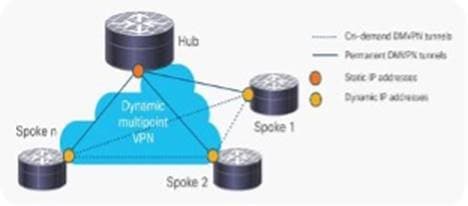
Deployment Scenario
1. Hub-and-Spoke Deployment Model
In this traditional topology, remote sites (spokes) are aggregated into a headend VPN device at the corporate headquarters (hub). Traffic from any remote site to other remote sites can pass through the headend device.
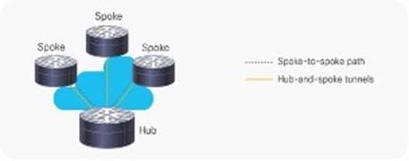
2. Spoke-to-Spoke Deployment Model
Cisco DMVPN allows the creation of a full-mesh VPN, in which traditional hub-and-spoke connectivity is supplemented by dynamically created IPsec tunnels directly between the spokes. With direct spoke-to-spoke tunnels, traffic between remote sites does not need to traverse the hub; this eliminates additional delays and conserves WAN bandwidth.
Onboarding New Router to SD-Routing
This section describes the onboarding of SD-routing enabled devices for both Greenfield and brownfield deployments.
Brown field Deployment
An existing router acting as DMVPN hub or spoke can be migrated to SD-Routing capable device either manually or seamlessly. The following sections cover both use cases.
Manual Migration Use Case for Brownfield
To migrate the existing spoke or a hub router to the SD-Routing, performs these steps
Step 1. Set up the controller in an on-prem or cloud environment.
Step 2. Upgrade the router through CLI to IOS XE 17.12.1 or higher version through image downloaded via tftp or any existing procedure to copy image
Step 3. Router Boot level: Set the router to network-advantage addon dna-advantage for enabling dna-advantage.
Step 4. License Migration: Migrate the bandwidth and crypto licenses to CSSM server and enable the smart license on the router, steps for license migration are explained below.
Step 5. User can enable WAN interface under sd-routing with any of the 5 options listed below
Note: enable Netconf-yang on global config
!
netconf-yang
!
Note: enable SD-Routing on global config
!
sd-routing
organization-name SD_Routing_DEMO
site-id 201
system-ip 10.100.1.1
vbond name vbond.cisco.com
WAN-interface TenGigabitEthernet0/1/1
!
Table 4. Wan interface options
| Wan Interface Type |
Controller reachable VRF |
Mode |
| All types of Ethernet interface |
Global |
Dedicated or Shared |
| Dot1q |
Global |
Dedicated |
| Port-channel |
Global |
Dedicated |
| Loopback |
Global |
Dedicated (Bound or Unbound) |
Option 1: Private Connection on Global VRF dedicated or shared interface
!
interface GigabitEthernet0/0/2
description WANINT
ip address 192.168.100.102 255.255.255.0
no ip redirects
load-interval 30
negotiation auto
arp timeout 1200
!
ip route 0.0.0.0 0.0.0.0 192.168.100.1
!
sd-routing
organization-name SD_Routing_DEMO
site-id 202
system-ip 10.100.2.1
vbond name vbond.cisco.com
Cisco Catalyst SD-WAN Validator, port 12346
WAN-interface GigabitEthernet0/0/2
!
Option 2: Private Connection on loopback interface bind to a Physical interface
!
interface Loopback1
ip address 1.1.1.1 255.255.255.255
!
interface GigabitEthernet0/0/1
description Lo1_bind_Physical
ip address 192.168.100.105 255.255.255.0
negotiation auto
!
ip route 0.0.0.0 0.0.0.0 192.168.100.1
!
SD-Routing
organization-name SD_Routing_DEMO
site-id 205
system-ip 10.100.5.1
vbond name vbond.cisco.com
WAN-interface Loopback1
!
Option 3: Private Connection on Global VRF sub-interface (dot1q)
!
interface TenGigabitEthernet0/0/1.100
encapsulation dot1Q 100
ip address 192.168.100.104 255.255.255.0
!
sd-routing
organization-name SD_Routing_DEMO
site-id 204
system-ip 10.100.4.1
vbond name vbond.cisco.com
WAN-interface TenGigabitEthernet0/0/1.100
!
Option 4: Private Connection on Global VRF with Port channel
!
interface Port-channel10
ip address 192.168.100.106 255.255.255.0
!
sd-routing
organization-name SD_Routing_DEMO
site-id 204
system-ip 10.100.4.1
vbond name vbond.cisco.com
WAN-interface Port-channel10
!
Option 5: Wan interface behind NAT for Cloud controllers
Routers having Private WAN connection are usually placed behind the NAT. NAT/FW router is configured to allow connection to desired ports to talk to cloud controllers. Either via Static or Dynamic Nat.
Step 6. Upload WAN edge details to Manager using either of the options noted below.
Option 1: Upload device information via CSV file
◦ Enable SD-Routing with below minimum config
netconf-yang
sd-routing
organization-name SD_Routing_DEMO
site-id 205
system-ip 10.100.5.1
vbond name vbond.cisco.com
WAN-interface GigabitEthernet0/0/0
Note: Wait for “All daemons are up for SD-Routing mode” message
◦ Collect Device details
Router#show SD-Routing certificate serial
Chassis number: C8300-2N2S-4T2X-FDOXXXXXXXX serial number: 02929A9A Subject S/N: FDOXXXXMXTX
Note: Fill the CSV file in # Format - chassis number, product id, cert serial number, sudi serial, device mode
◦ Generate CSV file
C8300-1N1S-6T-FDO2508M1NB,C8300-1N1S-6T,01176403661320850323,FDO2508M1NB,autonomous
C8300-2N2S-4T2X-FDO2444M1T4,C8300-2N2S-4T2X,02929D9D,FDO2444M1T4,autonomous
◦ Upload CSV file by Navigating to Configuration > Devices > WAN Edge List->Upload WAN Edge List
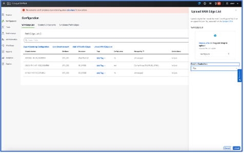
Note: Select “Yes” to send the Controllers options for syncing the device list with Validator to onboard the device.
Option 2: Upload devices Using Auto Sync
The auto sync method of uploading your devices to Cisco SD-WAN Manager can be used for both, deployments that include cloud controllers and deployments that include on-premises controllers, provided that Cisco SD-WAN Manager is able to connect with the Plug n Play (PnP) portal
◦ Log in to Cisco SD-WAN Manager using the admin credentials.
◦ To transfer device information from Cisco PnP portal to Cisco SD-WAN Manager, sync your Smart Account or Virtual account in Cisco SD-WAN Manager.
Note: You need Cisco credentials of the Virtual Account administrator role for this step. For more information about uploading the WAN Edge router serial numbers see
◦ From the Cisco SD-WAN Manager menu, choose Configuration > Devices. Click WAN Edge List, and click Sync Smart Account.
◦ In the Sync Smart Account window: Enter the Username and Password for your Smart account.
◦ To automatically validate the routers and send their chassis and serial numbers to the controllers, check the Validate the Uploaded WAN Edge List and Send to Controllers check box. If you do not select this option, you must individually validate each router in Configuration > Certificates > WAN Edge List.
◦ Click Sync.
Seamless Migration Use Case for Brownfield
An existing Router in an overlay can be seamlessly migrated with an upgrade, this workflow allows the device running an image earlier than Cisco IOS XE 17.12.1a to upgrade and then onboard seamlessly. This feature is applicable for the hardware devices only.
Prerequisite
● The device must be operational.
● To establish an SSH connection with the device, SSH connectivity from the Cisco SD-WAN Manager to the device with valid SSH username and password is needed. This user must have admin 15 privileges.
● Ensure that the software image is present on the device or the remote server (with .bin extension).
● Auto-boot needs to be enabled on the device
● You can use the SCP, FTP, and HTTP protocols to copy images from the remote server.
Limitations for Seamless Migration/upgrade
● Seamless upgrade is applicable only for hardware routing devices.
● SD-WAN Manager supports only VPN 512 and no other VPN for SSH connectivity.
● IOS XE 16.9.4 is the minimum base version tested for migrating to SD-Routing.
To migrate an existing router, perform these steps:
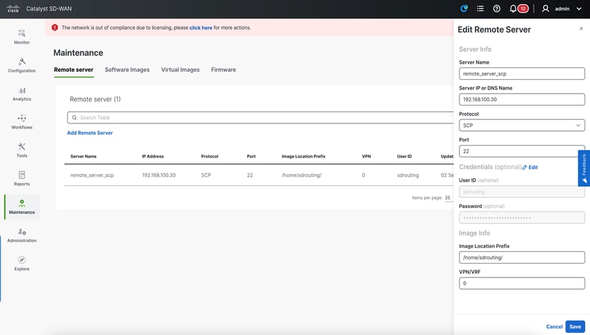
Step 1. Add an image to remote server by navigating to Maintenance > Software Repository > Remote Server and click on Add Remote Server.
Step 2. Enter the value for these fields:
● Server Name: Add a name for the server.
● Server IP or DNS Name: Enter the IP address of the server.
● Protocol: Select the protocol (FTP, SCP, HTTP) from the drop-down list over which you want to copy the image.
● Port: Enter the port on which the protocol is running.
● User ID: (Optional) Enter the user ID.
● Password: (Optional) Enter the password.
● Image Location Prefix: This is the location to search for images with .bin extension.
● VPN/VRF: Enter VPN or VRF which needs to be used to copy the image (This is not applicable for the HTTP protocol).
Step 3. Click Add to get the remote server added to the repository
Step 4. Add device under Tools > Upgrade for SD-Routing Capability > Add Device
Step 5. Add information for all mandatory parameters.
● IP Address: This is the IP address of the device that needs to be upgraded.
● Username: Enter the username.
● Password: Enter the password.
● Enable Password: (Optional) Enter a password only when you are not using a privilege 15 user.
● WAN Interface: The WAN interface name is required as a user data field in the bootstrap configuration file.
● Image on Device: If an image is stored on the device file system, you need to enter the image path. There are three ways to store images.
● Bootflash: If the image is stored inside the bootflash, enter "image_name.bin" as the image path.
● USB: If the image is stored on a USB, enter "usb0:image_name.bin" as the image path.
● Hard disk: If the image is stored on a harddisk, enter "harddisk:image_name.bin" as the image path.
OR
● Remote Server: If an image is stored on the remote server, add the image by following the steps provided Add an Image to the Remote Server.
● Remote Image Name: Applicable only if you choose the Remote Server option. Select the image from the drop-down list to upgrade.
● Actions: Click Save for these updates to be recorded.
Step 6. Save the device details and click Upgrade.
Greenfield Deployment
For onboarding a new router, you can connect through PnP or bootstrap workflow. For detailed steps, see https://www.cisco.com/c/en/us/td/docs/routers/sd-routing/1712x/sd-routing-onboard-routing-devices-to-sd-wan-manager-1712x.html
SD-WAN Manager Operation and Management
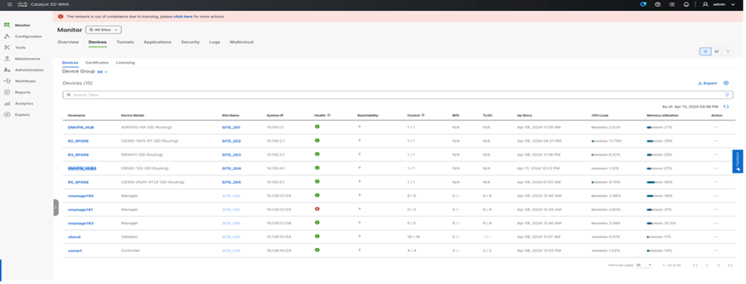
Monitoring
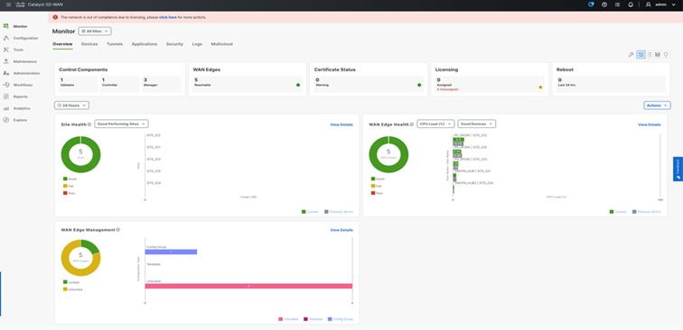
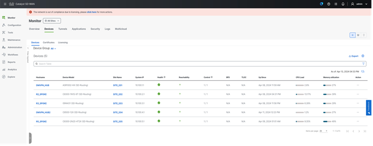
From 20.14 release onwards, SD-WAN Manager provides various operational capabilities to provide insight into the network and device level performance for SD-Routing. SD-WAN Manager provides monitoring capabilities such as Site health, WAN edge health, WAN Edge Management Applets on the Main Dashboard.
● Site Health: Displays overall health metrics for SD-Routing, the metrics is mainly based on site and device health.
● WAN Edge Health: Displays the overall device CPU, Memory, and TLOC reachability for the SD-Routing enabled devices.
● WAN Edge Management: Displays the Configuration Management status per device by type.
Performance Status and Stats
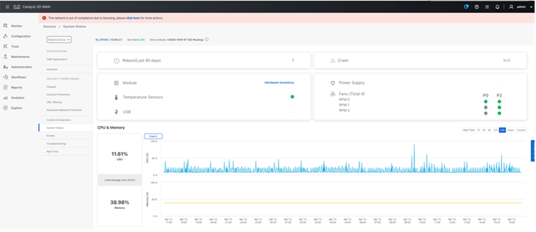
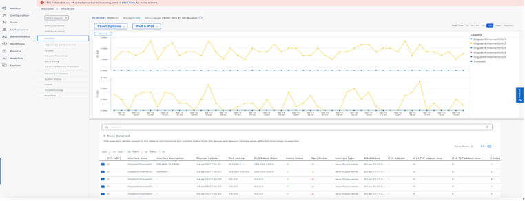
SD-Routing devices in 20.14 release provides per device hardware performance including Control plane CPU and memory and interface level utilization historical data under Monitor Device with default view as 24hours.

Event Monitoring
SD-Routing devices events like interface state change can be monitored on the Manager UI under Monitor > Devices for selected per device events which displays last 3h by default and can be customized to view historical data. The events are sent to the SD-WAN Manager over Netconf in a TLOC interface.
For the event to be monitored on the SD-WAN Manager, UI Control connection needs to be in Up state. Events happening after controller down state will not be captured in SD-WAN Manager UI.
Below are some of the supported events as of 20.14 release:
● Control connection State Change
● Site ID change
● System IP change
● Disk Usage
● Tloc Ip Change
● Interface State Change
Alarm Monitoring
SD-WAN Manager generates the Alarm when it receives the event from the SD-Routing enabled devices, which can be viewed under Monitor > Logs. By default, last 24h is displayed which can be customized for historical data, and the Alarm can be filtered per site.
These Alarms can be further redirected to webhook or SMTP server for email notification by additionally configuring Alarm Notification.
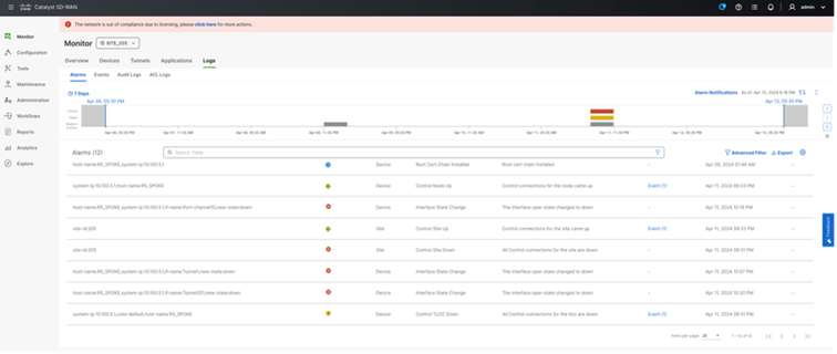
Below are some of the supported alarms as of 20.14 release:
● Interface State UP/Down
● Control Site UP/Down
● Control TLOC UP/Down
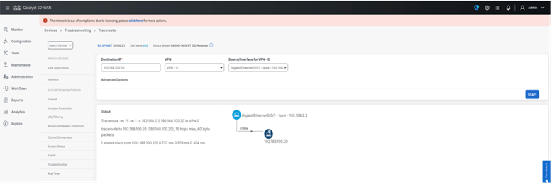
Troubleshooting
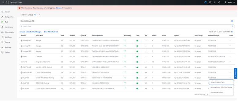
Troubleshooting can be performed from the SD-WAN Manager UI for the onboarded WAN edge device. The following are some of the capabilities in SD-WAN Manager supported for SD-Routing.
Supported Trouble shooting on SD-Routing devices:
● Real Time API Monitoring
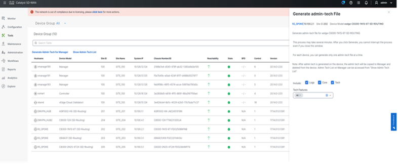
● Admin tech Collection
● Ping
● Traceroute
● Speed test
● Packet Capture
Real time API Query can be used for collecting status of the SD-Routing enabled devices through API. Also, user can select the required output from Device options.
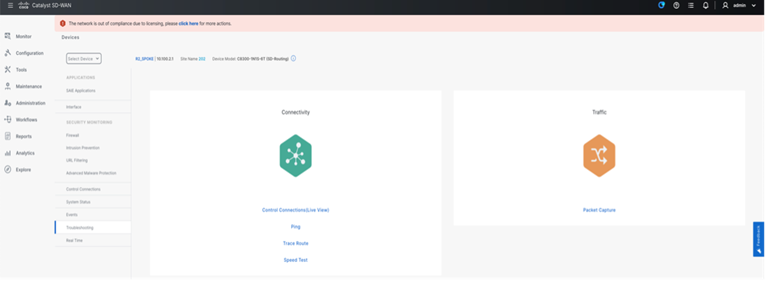
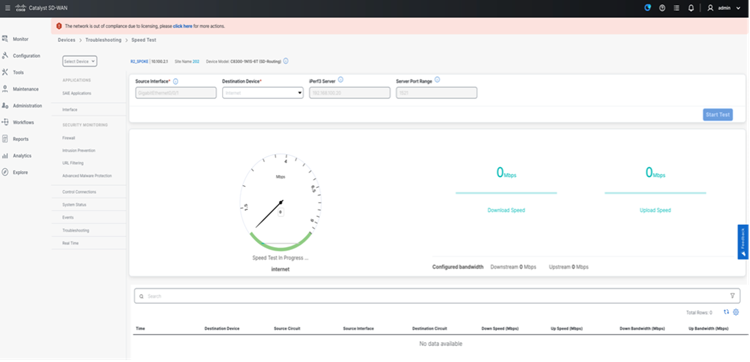
Admin tech can be collected from the SD-Routing enabled device from SD-WAN manager and can be downloaded once completed from the UI.
Provisioning Capabilities
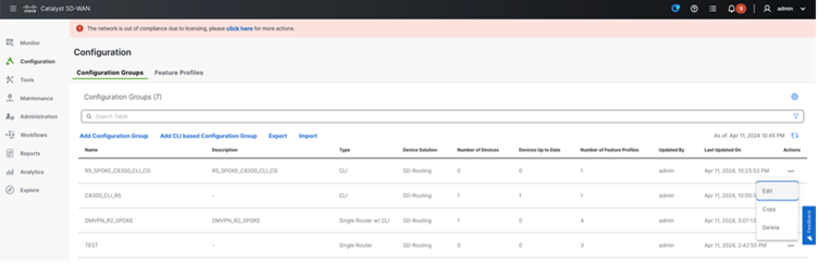
SD-WAN Manager comes with a workflow capability Configuration Group to simplify the device config provisioning over Netconf. You can perform configuration group deployment in two ways for SD-Routing:
1. CLI-based Configuration Group
2. Parcel-based Configuration Group
In 20.14 release SD-WAN Manager, user can associate selected devices and deploy user defined either CLI based Configuration group or Parcel based Configuration group for SD-Routing. It is recommended to use CLI based CG creation and deploy to selected devices.
This section explains how the CLI parcel is created and deployed to the selected devices.
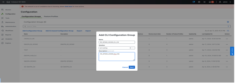
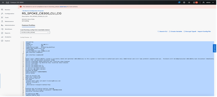
CLI-based Config Group
This section describes on the steps to create a config group
Step 1. Create CLI Config Group.
Step 2. Load config from reachable device.
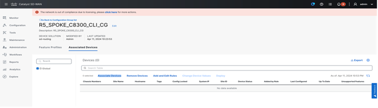
Step 3. Associate Devices: Configuration > Configuration Groups > Edit the Created Configuration Group
Step 4. Associate device

Step 5. Deploy the CLI Configuration Group to Associated devices.
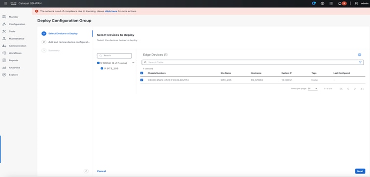
Note: While progressing to deploy, Preview CLI option can be verified to verify the config diff.
Parcel-based Configuration Group
Step 1. Create CLI Config Group and deploy to a reachable device.
● Navigate to Configuration > Configuration Groups > Add Configuration Group. Select “Create SD-Routing Config“.
● The 20.14 release supports 3 Config Parcel where various features can be configured as mentioned below.
1. System profile
◦ aaa
◦ banner
◦ global
◦ logging
◦ ntp
◦ SNMP
2. Transport & Management Profile
◦ Global VRF
◦ VRF
◦ Management VRF
◦ Route Policy
◦ Object Tracker
◦ Object Tracker Group
◦ ACL IPv4
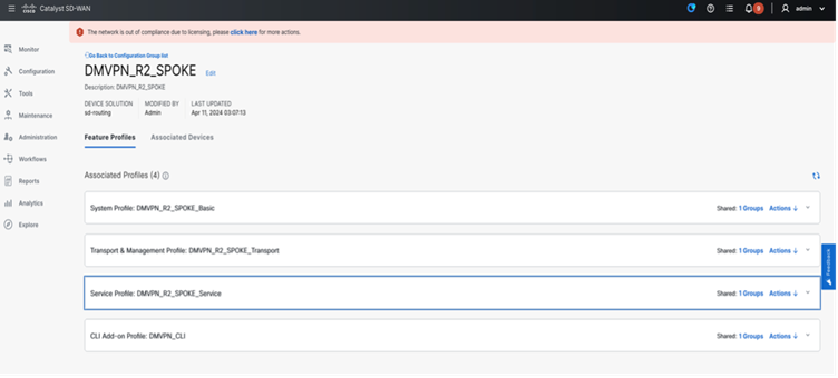
3. Service Profile
◦ VRF
◦ Route Policy
◦ Object Tracker
◦ Object Tracker Group
◦ ACL IPv4
◦ DHCP Server
Note: In case of additional Yang configuration is required to be provisioned to device and not present predefined Parcel, user can use CLI Addon to configure all the CLI.
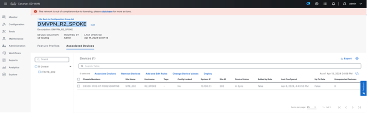
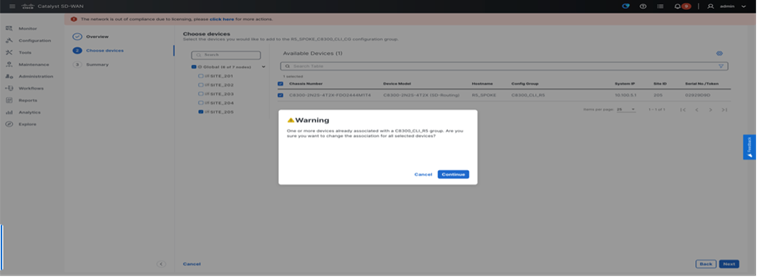
Step 2. Associate Devices
● Navigate to Configuration > Configuration Groups > Edit the Created Configuration Group “DMVPN_R2_SPOKE” > Associate Devices under Associated Devices.
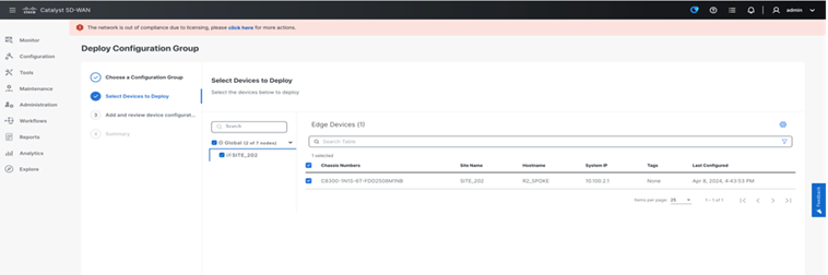
Step 3. Deploy the CLI Configuration Group.
● Navigate to Workflows > Deploy Configuration Group
Best Practices and Operation and Management
Below are some of the recommended best practices:
● All SD-Routing devices and SD-WAN Manager are synchronized to same clock source through NTP
● In 20.14 release, CLI based Config group is only supported.
● From 20.15 release onwards, Config group parcel can be used to deploy the configuration.
● Unique System IP and Site ID is used across the SD-Routing enabled devices.
● Remote servers are having the right images for respective platforms.
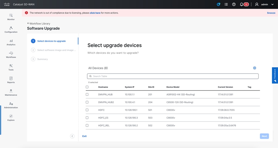
Upgrade Through SD-WAN Manager
Remote Server Setup FTP and HTTP
This feature enables SD-WAN Manager to upgrade the device or controller software using software images stored on a remote server. This feature allows you to register a remote server with SD-WAN Manager and add locations of software images on the remote server to the SD_WAN Manager software repository. When upgrade device or controller software is triggered, the device or controller can download the new software image from the remote server.
Scheduling and Preparing for Upgrade
Upgrade workflow helps to schedule the upgrade on planned maintenance window for the selected routers.
Version Compatibility Matrix with Controllers
Table 5. Version Compatibility matrix
| Controller Version |
IOS XE Version 17.12.x |
IOS XE Version 17.13.x |
IOS XE Version 17.14.x |
IOS XE Version 17.15.x** |
| 20.12.x |
Yes |
No |
No |
No |
| 20.13.x |
Yes |
Yes |
No |
No |
| 20.14.x |
Yes |
Yes |
Yes |
No |
| 20.15.x** |
Yes |
Yes |
Yes |
Yes |
Note: ** Recommended releases
SD-Routing Profile Validated in LAB
DMVPN HUB : C8500-12X4QC
DMVPN Spokes : C8500-12X4QC, C8500-12X, C8200-1N-4T, C8300-1N1S- 4T2X, C1131X-8PWB, C8530-12X
Table 6. SD-Routing Profile Validated in Lab
| Hardware Device |
Role |
Number of Tunnels |
Total Registrations |
Tunnel Source |
Route Scale |
| C8500-12X4QC |
HUB |
247 |
2570 |
HundredGigEthernet |
1M |
| C8530-12X (17.14) Green Field |
Spoke |
2 |
4 |
TenGigabitEthernet |
5K |
| C8500-12X |
Spoke |
2 |
4 |
TenGigabitEthernet |
5K |
| C8200-1N-4T |
Spoke |
90 |
180 |
GigabitEthernet |
4K |
| C8300-1N1S-4T2X |
Spoke |
1 |
5 |
TenGigabitEthernet |
4K |
| ISR4461/K9 |
Spoke |
247 |
492 |
TenGigabitEthernet |
1M |
Hub & Spoke : IOS XE 17.15
Controllers : 20.15, Multitenant, 3 node cluster
Config group push : C8500-12X4QC, C8500-12X, C8200-1N-4T, C8300-1N1S-4T2X, C1131X 8PWB, C8530-12X
SSLProxy : C8300-1N1S-4T2X
Monitoring : Alarms, interface state, tunnel state
Upgrade : upgrade from SD-WAN Manager through remote server
Troubleshooting : Speed test, Real time monitoring, Pack capture and admintech
Security policy : C8500-12X4QC, C8500-12X
Routing features : BGP, EIGRP, Zone based firewall with OGACL, NAT, NAT redundancy, nat64,
nat map-t BR, ikev2, NHRP, DMVPN, FNF, HSRP, QOS, NetFlow