Cisco Unified Branch Design Guide
Available Languages
Bias-Free Language
The documentation set for this product strives to use bias-free language. For the purposes of this documentation set, bias-free is defined as language that does not imply discrimination based on age, disability, gender, racial identity, ethnic identity, sexual orientation, socioeconomic status, and intersectionality. Exceptions may be present in the documentation due to language that is hardcoded in the user interfaces of the product software, language used based on RFP documentation, or language that is used by a referenced third-party product. Learn more about how Cisco is using Inclusive Language.
- US/Canada 800-553-2447
- Worldwide Support Phone Numbers
- All Tools
 Feedback
 Feedback
Branch offices across industries require continuous operations, strong and future-ready security, and excellent customer experience. At the same time, IT teams must deliver these outcomes with limited resources. Teams also face increasing operational complexity, growing security vulnerabilities, rising traffic volumes, and stricter uptime demands driven by AI and IoT initiatives.
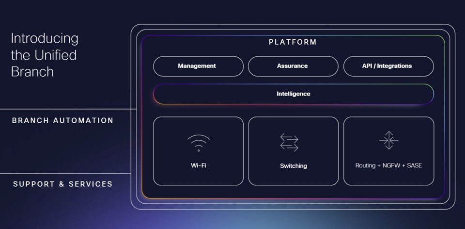
Cisco designed the Unified Branch full-stack solution to help organizations deploy branches faster, simplify operations, scale more easily, and reduce maintenance effort. Unified Branch combines routing, next-generation firewall, Wi-Fi, IoT, and switching into a validated solution managed through a single dashboard. Cisco built Unified Branch on Cisco Validated Designs (CVDs), which provide prescriptive, tested designs that apply Cisco best practices to accelerate implementation and reduce risk.
Cisco embeds security throughout the network fabric and across multiple devices and layers. The solution includes next-generation firewall, identity services, zero-trust segmentation, and future post-quantum cryptographic safeguards. Cisco Extended Detection and Response (XDR) improves security operations by detecting, prioritizing, and remediating threats more efficiently.
Cisco’s unified management platform provides network visibility and detailed path and performance insights through ThousandEyes. Cisco also adds AgenticOps—AI-driven operations backed by Cisco expertise—to help IT teams automate and manage networks more intelligently with Cisco AI Canvas and Cisco AI Assistant for AI-driven monitoring, troubleshooting, and remediation.
Branch as Code (BaC) applies Infrastructure as Code (IaC) principles to branch deployment and operations. BaC lets enterprises deploy, manage, and scale branch infrastructure with greater agility, consistency, and confidence by using Cisco validated designs and automation frameworks. Cisco Workflows provides another flexible automation option for streamlining deployment and operational tasks.
About this guide
Cisco develops, tests, and releases the Unified Branch architecture in phases. In the current phase, Cisco introduces medium and large branch designs in addition to the previously introduced small branch design. This phase supports multiple MX models, Cisco secure routers, Cisco switches, and APs managed through the Meraki Dashboard, with Auto VPN delivering the SD-WAN overlay. Catalyst switches must run in cloud mode (not device mode), so administrators must manage and configure them only from the Meraki Dashboard.
Cisco Unified Branch CVD documentation includes this design guide plus separate deployment guides. This design guide presents architecture overviews for small, medium, and large branches, including supported hardware, services, and features, and outlines configuration choices for each branch type. The deployment guides provide detailed, step-by-step implementation procedures, for example small branch, medium branch, and large branch branch deployments. Appendix A lists links to related Unified Branch documentation.
This guide does not cover BaC or Cisco Workflows in detail. Separate documentation covers those topics. However, this guide’s architecture and design align closely with what BaC and Workflows implement. While Cisco integrates best practices throughout, current automation capabilities influence some design decisions.
Unified Branch high-level architecture
Overview
Unified Branch implements a full-stack branch design with secure routers, switches and/or switch stacks, and APs that support wired and wireless clients, voice, and video. The services listed in the table are implemented:
Table 1. Unified Branch services
| Services |
|||
| Routed Mode |
Dual WAN |
VLAN Interfaces |
DHCP – local and centralized |
| Auto VPN – Hub and Spoke |
VPN Site-to-Site Firewall |
Local Router Firewall |
Secure Internet Access: Cisco Secure Access Multi-Uplink Tunnels |
| Local Internet Breakout (DIA) |
SD-WAN Performance-based Policies |
SD-WAN Traffic Steering Policies |
Traffic Shaping |
| Threat Protection |
Content Filtering |
Spanning-tree Protocol |
Quality of Service |
| Storm Control |
802.1x/MAB for Wired Clients (Centralized RADIUS Server) |
802.1x for Wireless Corporate Clients (centralized RADIUS Server) |
Guest Wireless |
| Wireless External DHCP Server/Bridged Mode |
Wireless Firewall and Traffic Shaping |
SSID Availability |
AI-Enhanced Radio Resource Management |
| Per-SSID Band Selection and Band Steering |
Other Network Services (SNMP Traps, Polling, Syslog, NetFlow) |
Adaptive Policy |
Thousand Eyes, Splunk, XDR |
Branch types
Branches can be classified in several ways, based on branch network architecture, number of users, bandwidth requirements, device support, WAN transports, branch physical size, network complexity, key features, and so on. In this phase of Unified Branch, small, medium, and large branches are defined based on network architecture characteristics. This table summarizes the characteristics of each branch type:
Table 2. Unified Branch type characteristics
| Characteristic |
Small branch |
Medium branch |
Large branch |
| Single Secure Router |
X |
|
|
| Dual Secure Routers |
|
X |
X |
| One Single-layer Layer 2 Switch or Switch stack |
X |
X |
|
| One Layer 2 Distribution-layer Switch Stack |
|
|
X |
| One or more Layer 2 Access-layer switches or switch stacks |
|
|
X |
| One or more Access Points (APs) |
X |
X |
X |
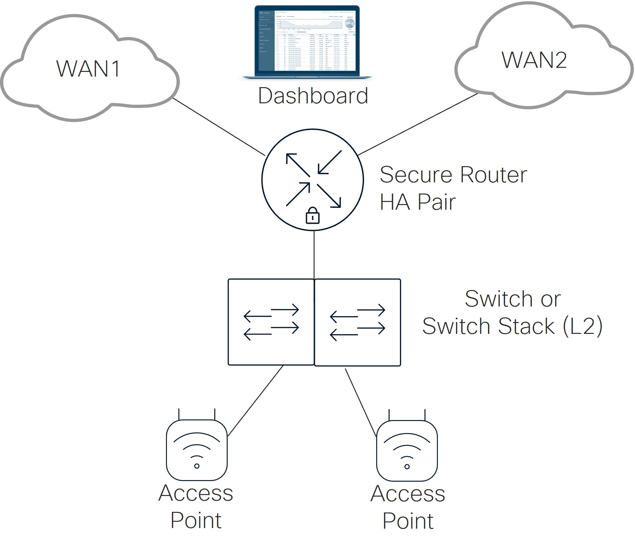
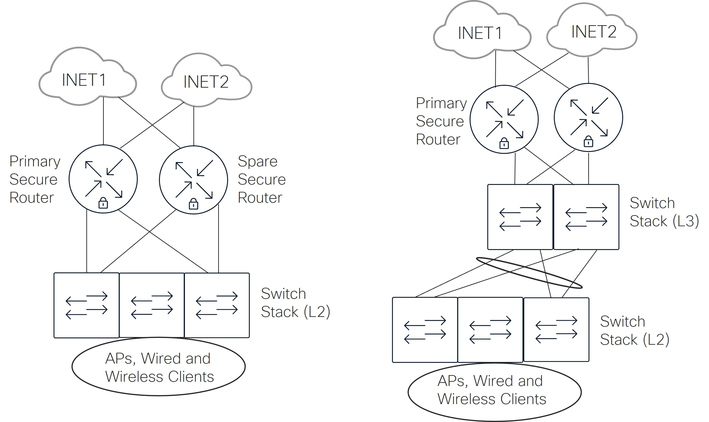
The small and medium branch topologies are similar, but the medium branch introduces a high-availability pair of secure routers, where one router is active and one router is passive. The large branch leverages a high-availability pair of secure routers as well, but implements a hierarchical LAN design, introducing a single layer-2 distribution layer switch stack, where multiple access switches and/or switch stacks are connected.
Small and medium branch topologies are defined as a single switch or switch stack. If more than a single switch or stack is required due to physical distance limitations within the branch, it is recommended to transition to the large branch design, which implements a layer-2 distribution layer and separate access layer.
Ideally, the large branch should implement a layer-3 distribution layer to help offload the routing of east-west traffic, but due to automation restrictions and gaps at the time of this writing, a layer-2 distribution layer is introduced, and a layer-3 distribution layer is coming in a future release.
There are no validation checks in the automation on which platform models are supported in each branch topology. The user needs to ensure that the platforms chosen and the link bandwidths can support the required number of wired and wireless users and their application and network requirements. In addition, PoE requirements for APs and other devices need to be considered when choosing platforms.
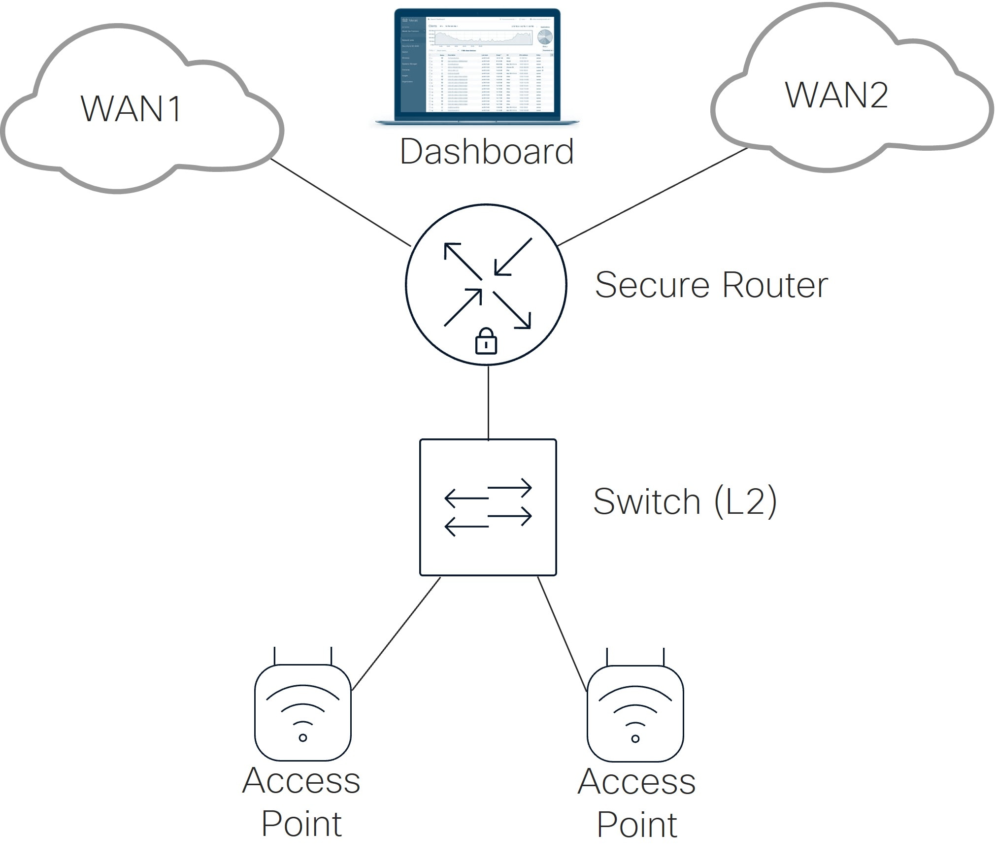
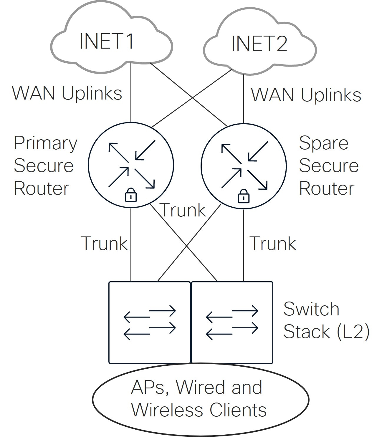
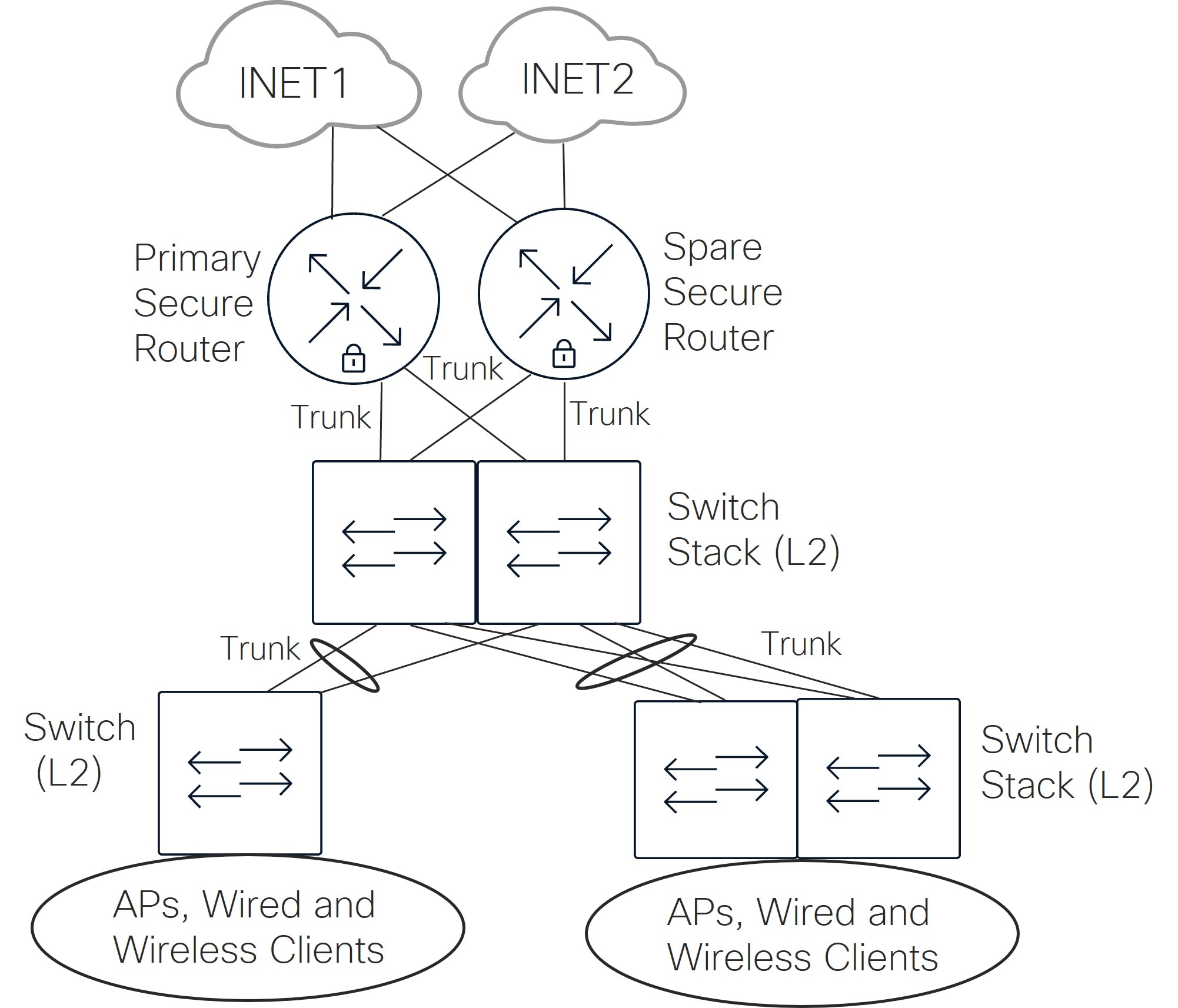
Small branch
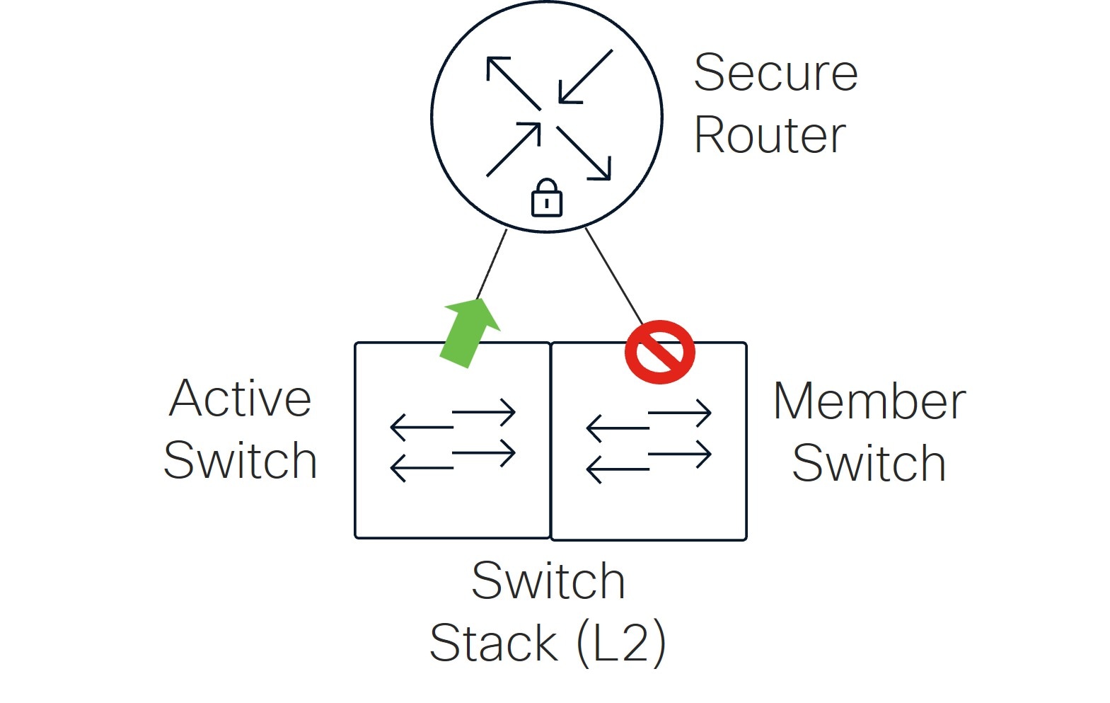
Refer to the diagram highlighting the small branch. At the branch, there is one secure router, one layer 2 switch or switch stack, and one or more APs. The secure router has 2 active WAN uplinks where each uplink goes to a different WAN transport where each transport has connectivity to the dashboard. It also terminates layer 3 connectivity for several groups of users at the branch. The group of users are segmented at the switch layer by VLANs, and the VLANs are trunked from the switch or switch stack to the secure router.
Note: The MX devices are often referred to as security appliances in documentation and the dashboard. In this document, they are referred to as routers or secure routers.
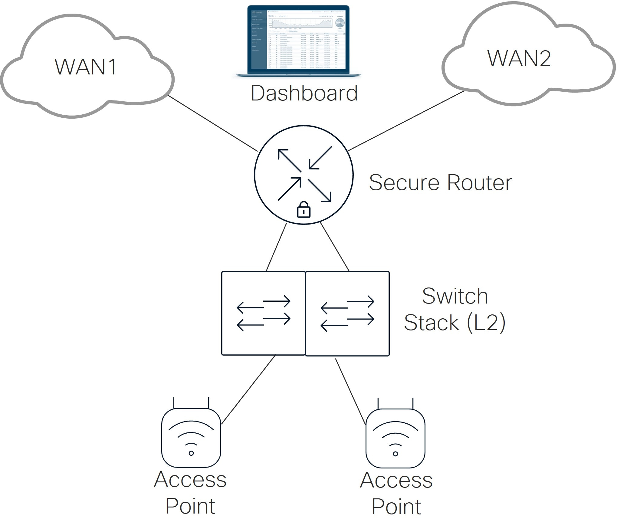
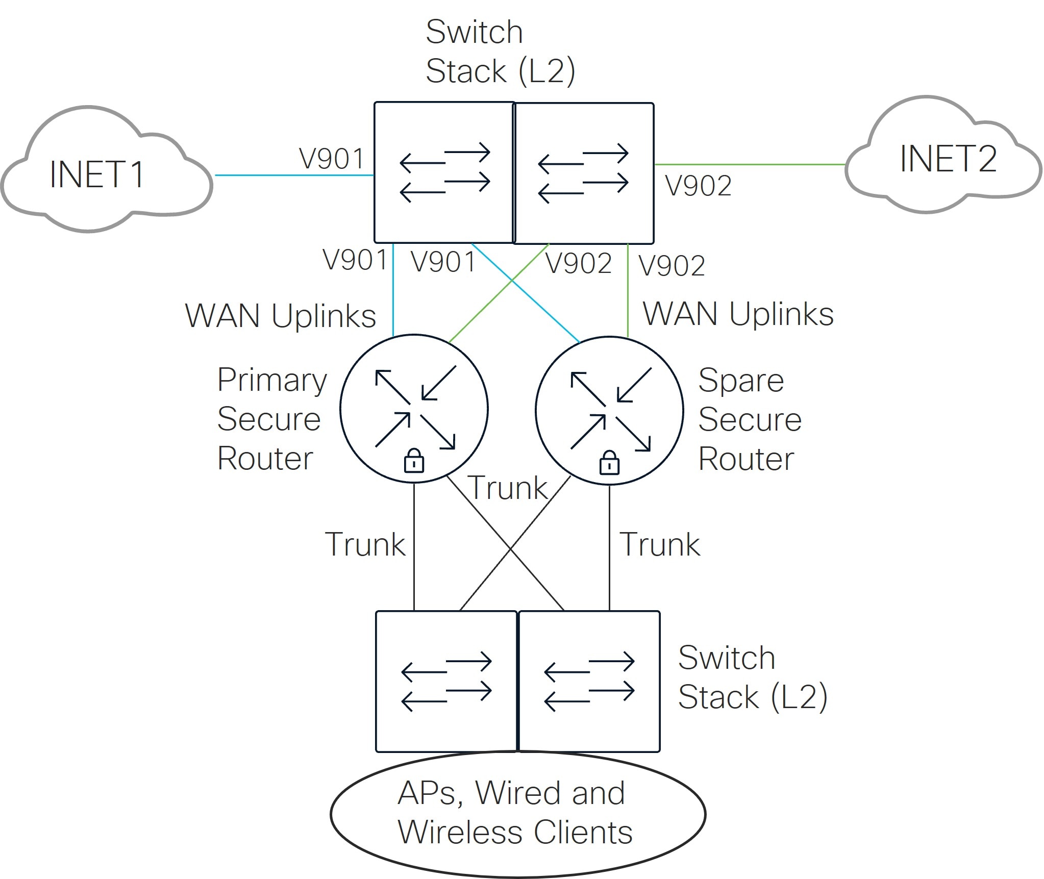
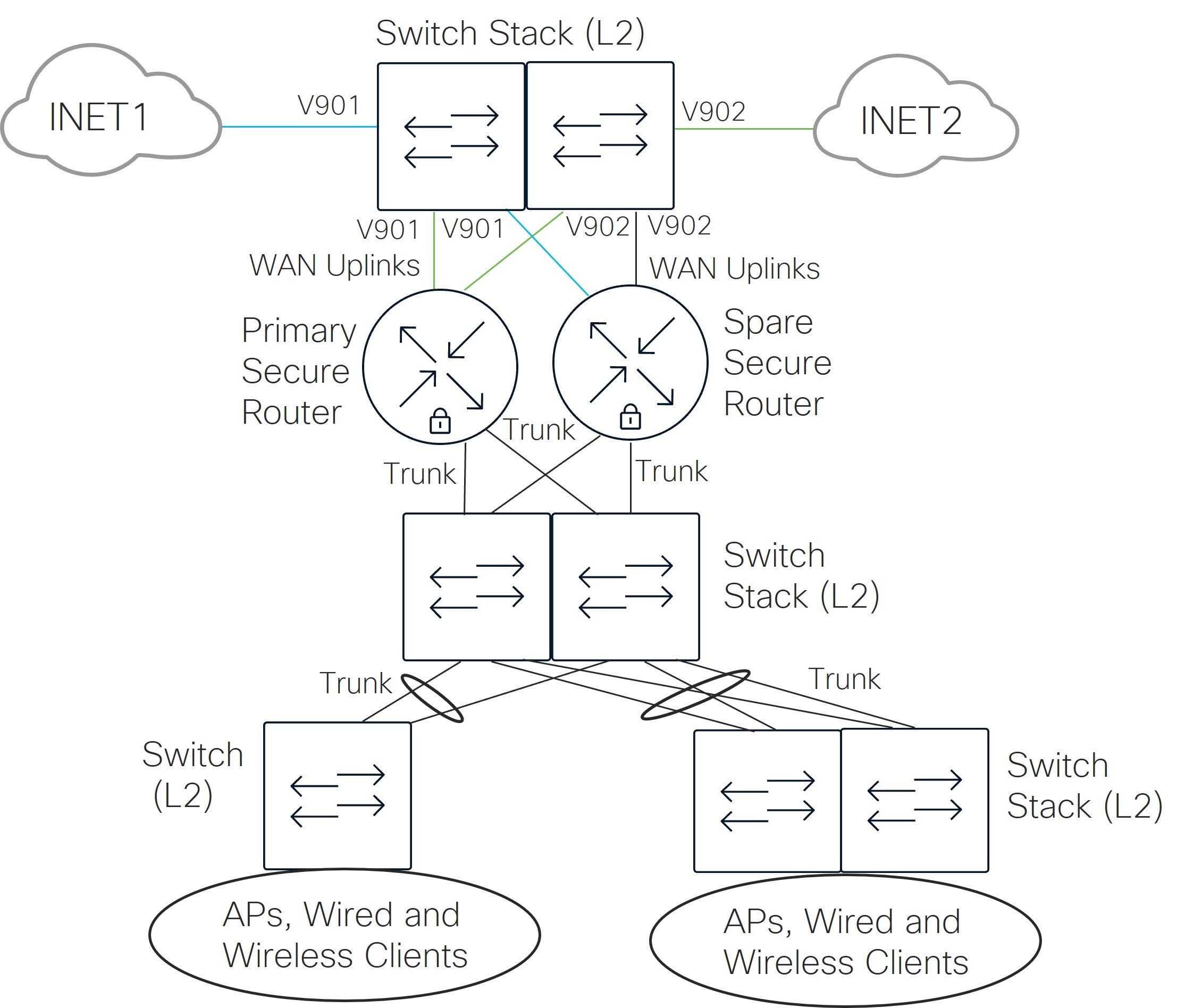
Medium Branch
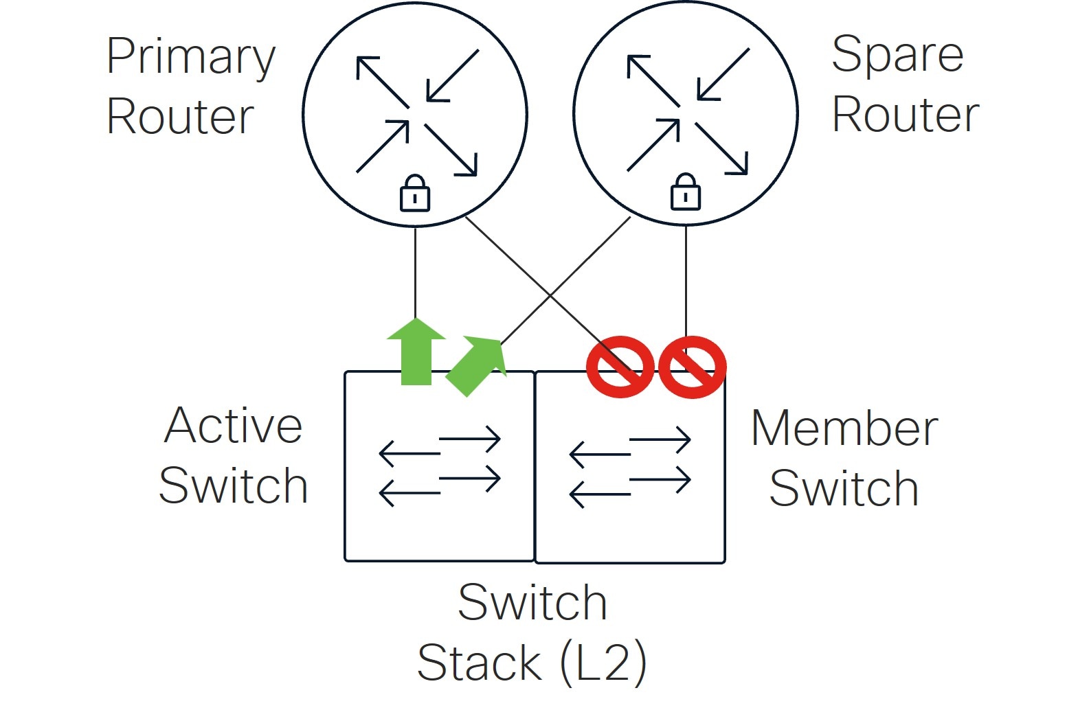
A medium branch uses two secure routers in an HA pair, one L2 switch or switch stack, and one or more APs. Each router uses two active WAN uplinks connected to different transports with dashboard reachability. The active router terminates L3 services for user groups segmented by VLANs on the switch layer. The switch trunks those VLANs to the secure router pair.
Physical topology
There are several physical options for the medium branch topology:
1. Connect each secure router to each transport provider: This requires two physical Ethernet handoffs from each transport provider.
2. Repurpose ports from the switch or switch stack to front-end the secure routers: This requires only one single Ethernet handoff from each WAN service provider which needs to connect to both the primary and secondary secure routers. It is recommended to leverage a switch stack in this design so there is not a single point of failure for transport reachability. The same WAN uplink on both secure routers should connect to the same switch/transport. Switch ports designed for transport are configured as access ports, one transport for VLAN 901, and the other transport for VLAN 902. These VLANs provide layer 2 passthrough connectivity from the WAN service provider physical Ethernet handoff to the WAN uplinks of the secure routers. These VLANs should be pruned off all trunks in the network.
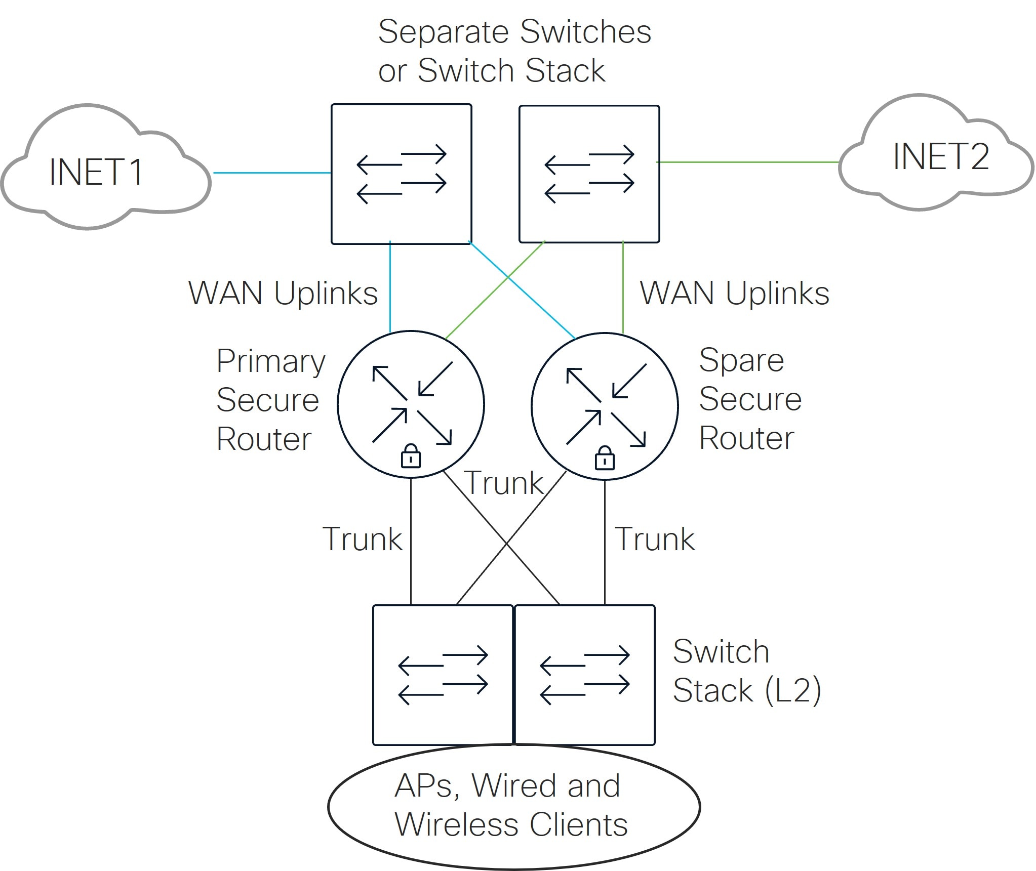
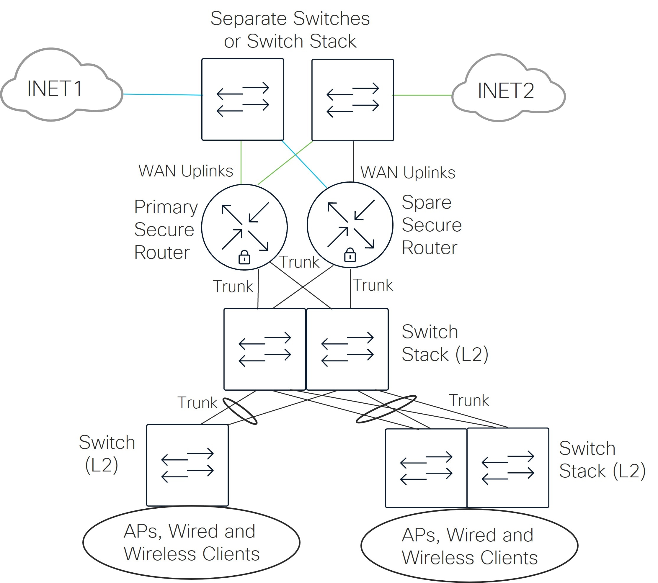
3. Implement separate managed switches to front-end the secure routers: This option also requires one single Ethernet handoff from each WAN service provider which needs to connect to both the primary and secondary secure routers, but instead of leveraging the switch or switch stack that provides connectivity for both the WAN and LAN, separate switches or switch stack provide the WAN connectivity. Compared to the previous option, this option may alleviate security concerns should the switches be misconfigured or returned to a factory default configuration, or it may reduce some complexity during the initial bring-up of the branch. However, adding extra switches or switch stack would add extra space, power, and management requirements.
Note: It is recommended to leverage at least two switches or a switch stack in this design so there is not a single point of failure for transport reachability.
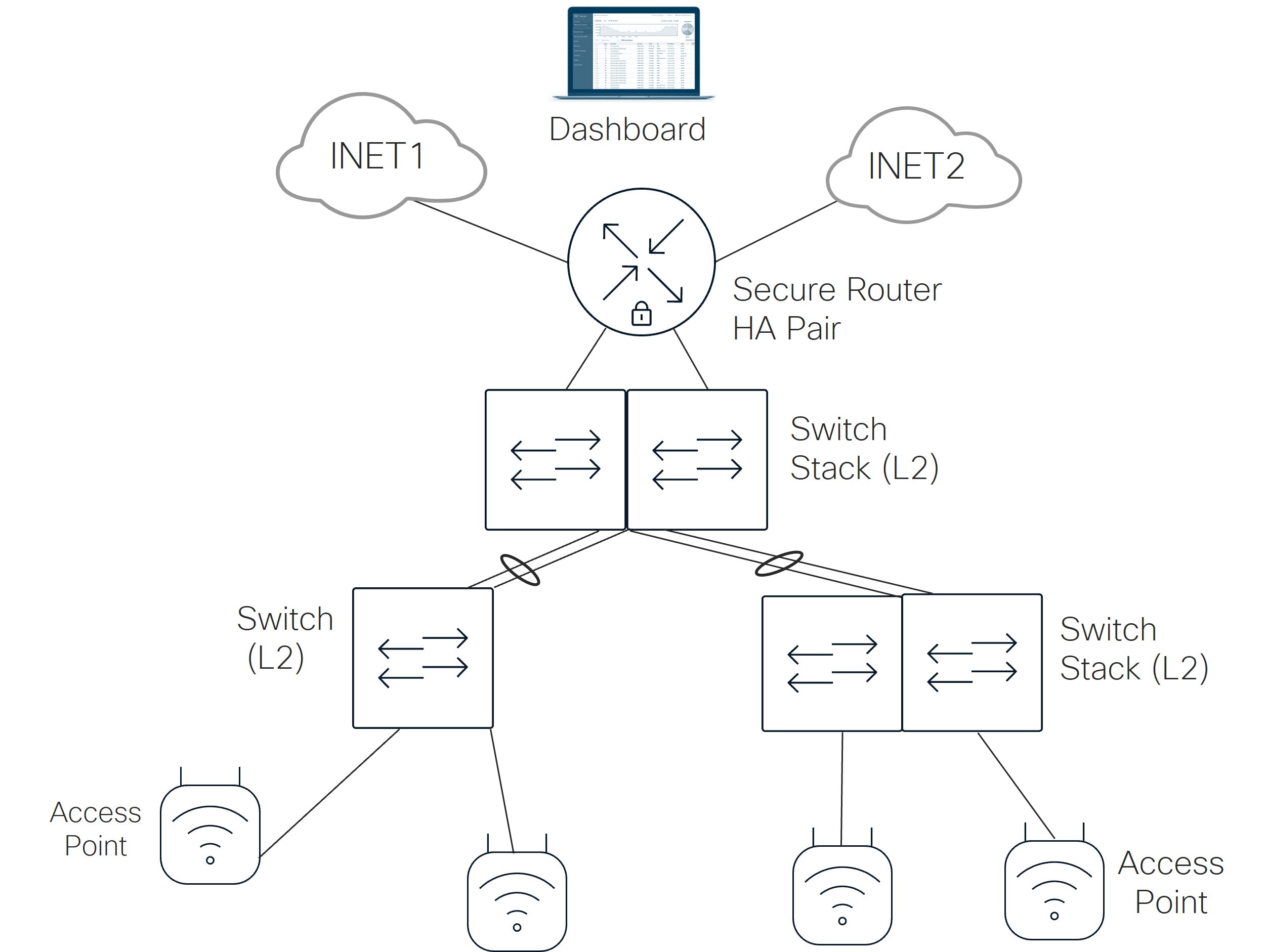
Large Branch
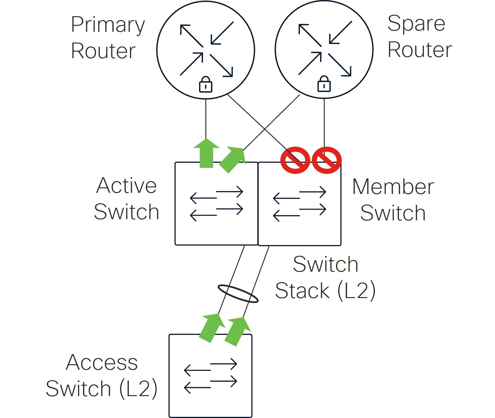
Refer to the diagram highlighting the large branch. At the branch, there are two secure routers in a high-availability pair configuration, one layer 2 distribution stack switch, one or more layer 2 access switches and/or switch stacks, and one or more APs. Each secure router has two active WAN uplinks, each uplink going to a different WAN transport where each transport has connectivity to the dashboard.
The active secure router terminates layer 3 connectivity for several groups of users at the branch. The group of users are segmented at the switch layer by VLANs. The VLANs are trunked between the distribution switch stack and the pair of secure routers, as well as between the distribution switch stack and each access switch or switch stack. The distribution switches must be able to support physical stacking in this design.
Note: The MS130 model of switches do not support physical stacking.
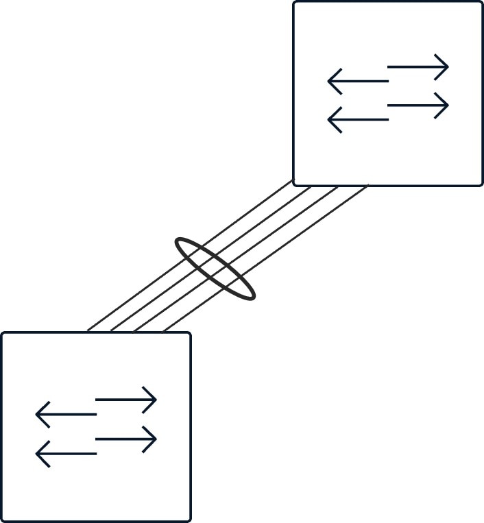
Each access switch uses two uplinks configured as an aggregated link to the layer 2 distribution switch stack, and each access switch stack uses at most four uplinks (two from each of two switches) configured as an aggregated link to the layer 2 distribution switch stack.
Physical topology
Like the medium branch, there are several physical options for the large branch topology:
1. Connect each secure router to each transport provider: This requires two physical Ethernet handoffs from each transport provider.
2. Repurpose ports from the distribution layer switch stack to front-end the secure routers: This requires only one single Ethernet handoff from each WAN service provider which needs to connect to both the primary and secondary secure routers. The same WAN uplink on both secure routers should connect to the same switch/transport. Switch ports designed for transport are configured as access ports, one transport for VLAN 901, and the other transport for VLAN 902. These VLANs provide layer 2 passthrough connectivity from the WAN service provider physical Ethernet handoff to the WAN uplinks of the secure routers. These VLANs should be pruned off all trunks in the network.
3. Implement separate managed switches to front-end the secure routers: This option also requires one single Ethernet handoff from each WAN service provider which needs to connect to both the primary and secondary secure routers, but instead of leveraging the layer 2 switch stack that provides connectivity for both the WAN and LAN, separate switches or switch stack provide the WAN connectivity. Compared to the previous option, this option may alleviate security concerns should the switches be misconfigured or returned to a factory default configuration, or it may reduce some complexity during the initial bring-up of the branch. However, adding extra switches or a switch stack would add extra space, power, and management requirements.
Note: It is recommended to leverage at least two switches or a switch stack in this design so there is not a single point of failure for transport reachability.
Port reservation
The design makes assumptions about what the ports on each device are used for (for ease in automation), and any ports that are unused are disabled. For more detailed information, refer to the deployment guides for each branch type listed in Appendix A.
Unified Branch components
This section details the platform support, licensing, and hardware components within the Unified Branch architecture design.
Licensing
Unified Branch does not require any additional or special licensing – it is available by default with valid hardware and licenses. Each device requires a valid license to operate. Licenses are required to get centralized management, network-wide visibility and control, support, and firmware and security updates. For licensing models, subscription licensing is recommended, but co-term licensing is also supported. Within each license model, different licensing levels or options give access to different features. Also, for certain features, additional licensing is required. For example, XDR requires an Advanced Security or SDWAN+ co-term license, or Essentials or Advantage subscription license for the network device, but an XDR subscription license is also required in order to be able to use the service.
Table 3. Licensing for Unified Branch use cases
| Component |
Licenses |
Subscription License |
Co-term/Term License |
| Secure Routers |
Subscription or Co-term |
Advantage |
Secure SD-WAN Plus |
| Switches |
Subscription or Co-term |
Advantage |
Advanced |
| Wireless LAN APs |
Subscription or Co-term |
Advantage |
Advanced |
| Cisco Secure Access |
Subscription |
N/A |
|
| Thousand Eyes |
N/A |
N/A |
|
| Splunk |
Term for On-prem/Subscription for Cloud |
||
| XDR |
Subscription |
N/A |
Platform support
This section describes the hardware supported in this phase of the Unified Branch architecture.
For the Catalyst switches (C9200/L/CX and C9300/X/L/LM), they must be able to run in cloud mode for full Meraki dashboard-delivered management. Cloud mode delivers a complete cloud management experience, supporting UI or API-driven configuration, simplified management, and centralized visibility. The original cloud mode operating system for Catalyst switches is the CS17 version, which is a combination of IOS XE and a container-based Meraki Management layer.
The Catalyst 9200/9300 switches can optionally be ordered with a SKU ending in -M. These models arrive in cloud mode and can be immediately onboarded to the dashboard. Any non-M versions need to be migrated to cloud mode. Cloud native IOS XE 17.15 and 17.18 have now been released, and these images are the release of choice for cloud mode Catalyst devices moving forward. Migration is also recommended from CS code to cloud native IOS XE code. Refer to Cloud Management with IOS XE Overview for more detailed information on SKU support, minimum versions for cloud management, and migration.
Note: When a Catalyst switch has been upgraded to IOS XE, it is restricted from downgrading back to a prior CS-based firmware. In a single network, only one firmware version for Meraki switches and one firmware version (CS or IOS XE) for Catalyst-based switches can co-exist. If different code versions need to be run within a network, a different network needs to be created for those devices.
The software minimum in the table reflects the minimum software tested and minimum software required for the various use cases implemented for this phase of Unified Branch. The recommendation is to use the latest stable release version for each platform.
Table 4. Unified Branch platform and software support with links to data sheets
| Component |
Model Family |
Software Minimum |
| Secure Router |
*MX67/MX68/MX75/MX85/MX95/MX105/MX250/MX450/C8455-G2-MX/C8121-G2-MX |
MX 19.2 |
| Switch |
CS 17/IOS XE 17.15 or 17.18 depending on the model (minimum required version) |
|
| Switch |
IOS XE 17.15 or 17.18, depending on the model (minimum required version) |
|
| Switch |
IOS XE 17.18 |
|
| Switch |
MS 17.2 |
|
| Wireless LAN APs |
MR 31.1 |
*For the MX67/MX68 models, the integrated wireless and/or cellular functions are not supported today in the Unified Branch design. In addition, a switch or switch stack is required for LAN connectivity within the branch.
Check each model family’s data sheet in the table above for stack cabling SKUs for switch stacking use cases.
The network devices require onboarding to the dashboard to be properly managed. Before attempting to onboard a device to the dashboard, ensure all the dashboard pre-requisites are met. This includes claiming devices, adding licenses, and configuring networks. Refer to the Getting Started Checklist for additional information. Also refer to the deployment guide links in Appendix A for onboarding examples.
Unified Branch secure router
Unified Branch in this phase supports several flavors of secure routers:
· MX67/MX68
· MX85
· MX95
· MX105
· MX250
· MX450
· C8455-G2-MX
· C8121-G2-MX
Router sizing and throughput requirements
When selecting a secure router, there are several factors to consider, such as firewall, VPN, and IDS/IPS throughput, number of users and devices, number of tunnels, and maximum concurrent sessions. For a hub and spoke topology, tunnel count for a branch is typically not an issue.
The aggregate throughput requirements of the secure router within a branch site should be determined based on the number of clients and each client’s application requirements and traffic expectations, including what percentage of throughput is leveraging particular security features, how much is sent DIA/SIA, and how much is sent across the Auto VPN fabric. The properly sized secure router should be chosen to accommodate the requirements, also ensuring that downlink speeds to the switch/switch stack and WAN transports speeds are adequate and can accommodate for future growth.
Refer to MX Sizing Guide and Principles for more detailed information, as well as the Meraki Sizing Tool for choosing platforms. Refer to the individual datasheets in Table 4 for specifics on interface types, performance capabilities, physical characteristics, and so on.
Deployment mode
The secure WAN router can be deployed in either Routed (default) or Passthrough (VPN Concentrator) mode. For this design, routed mode is enabled for the branch router.
In routed mode, the WAN router acts as a layer 3 gateway for subnets configured on the LAN side, and routes encrypted traffic over the Auto VPN overlay to other sites or internet traffic out the WAN uplinks to the internet. Client traffic to the internet is translated using NAT overload so its source IP address is the uplink IP address of the WAN router uplink. This mode is best if layer 3 networking capabilities are required and the WAN router is connecting directly to the internet demarcation point with a public IP address issued by the service provider. Routed mode is the most common branch deployment model.
WAN connectivity
MX67/MX68
The MX67/68 has 2 ports that can be used for WAN connectivity. The MX68 has 2 dedicated WAN ports and the M67 has one dedicated WAN port, but port 2 (LAN port) can be converted to a WAN port for the second uplink.
Table 5. MX67/MX68 WAN interfaces
| Secure Router |
WAN interfaces |
Port numbers |
| MX67 |
1x dedicated 1 Gigabit Ethernet RJ45 |
Port 1 |
| MX68 |
2x dedicated 1 Gigabit Ethernet RJ45 |
Ports 1-2* |
*Ports 1 and 2 on the MX68 support PoE+, which could be used to support a WAN gateway device, such as a cellular gateway, or satellite or cable modem.
MX75/MX85/MX95/MX105
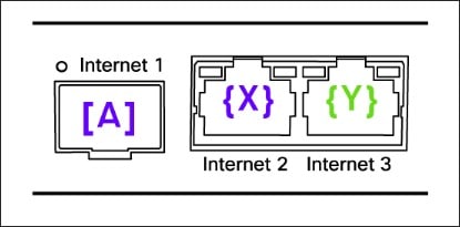
The MX75 has 3 total possible ports that can be used for WAN connectivity, which are represented by this table:
Table 6. MX75 WAN interfaces
| Secure Router |
WAN interfaces |
Port pairing |
| MX75 |
1x dedicated 1 Gigabit Ethernet SFP |
Port 1 (SFP) – Port 2 (RJ45) |
If an SFP is detected at device boot for port 1, then that port is enabled, and its RJ45 port pair partner is disabled (port 2). If an SFP is not detected at device boot for port 1, then that port is disabled, and its RJ45 port pair partner is enabled (port 2). Port preference is retained until the next boot, even if an SFP is removed during device operation. Port selection can also be configured through the device’s local status page and not through the main dashboard.
The MX85/95/105 has 4 total possible ports that can be used for WAN connectivity, which are represented in this table:
Table 7. MX85/MX95/MX105 WAN interfaces
| Secure Router |
WAN interfaces |
Port pairing |
| MX85 |
2x dedicated 1 Gigabit Ethernet SFP |
Port 1 (SFP) – Port 3 (RJ45) |
| MX95/MX105 |
2x dedicated 10 Gigabit Ethernet SFP+ |
Port 1 (SFP) – Port 3 (RJ45) |
If an SFP is detected at device boot for port 1 or 2, then that port is enabled, and its RJ45 port pair partner is disabled (port 3 or 4). If an SFP is not detected at device boot for port 1 or 2, then that port is disabled, and its RJ45 port pair partner is enabled (port 3 or 4). Port preference is retained until the next boot, even if an SFP is removed during device operation. Port selection can also be configured through the device’s local status page and not through the main dashboard.
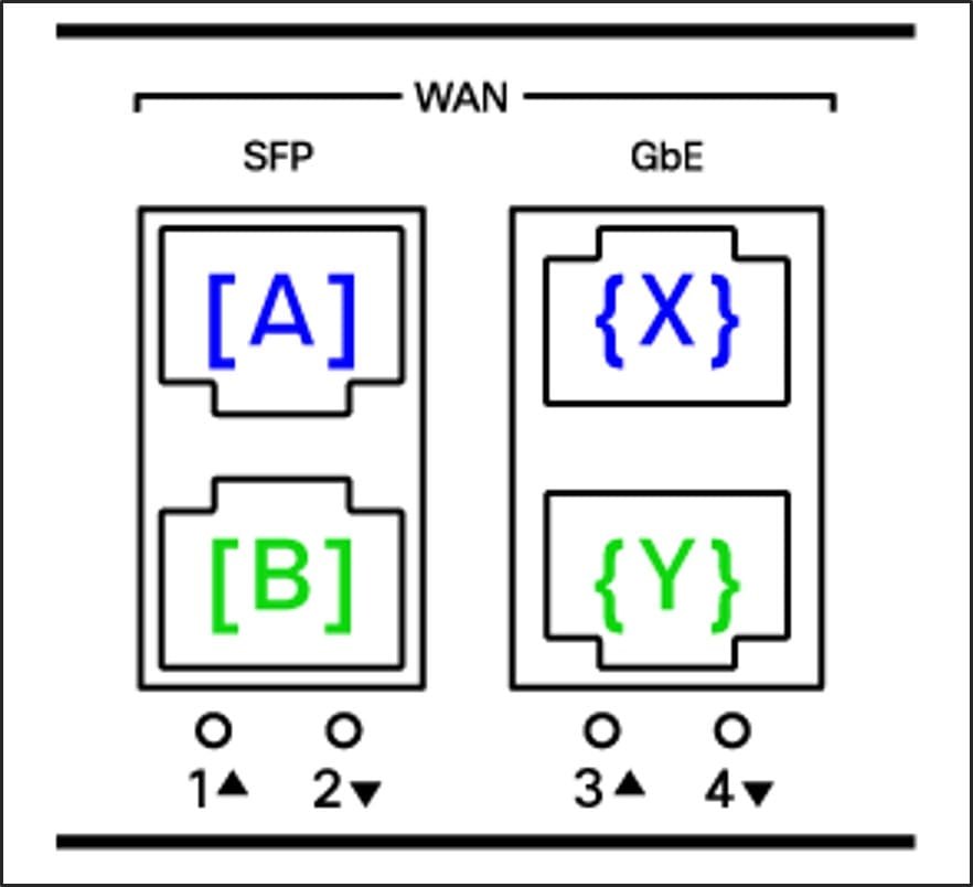
Port 4 on each MX85/MX95/MX105 model supports PoE+, which could be used to support a WAN gateway device, such as a cellular gateway, or satellite or cable modem. For more information, refer to the WAN Behavior on MX75/85/95/105 document.
MultiWAN Backup Uplink
The MultiWAN Backup Uplink feature enables a third link as a backup link and it only is supported on MX75, MX85, MX95, and MX105. The third link stays in standby mode until both the primary and secondary uplinks are down. On the MX75, port 3 becomes the designated backup port, port 1 becomes WAN 1, and port 2 becomes WAN 2. On the MX85, MX95, and MX105, port 4 is the designated backup port, port 1 becomes WAN 1, port 2 becomes WAN 2, and port 3 is disabled and unusable.
If the backup uplink is enabled at some point, it is best to use physical ports 1 and 2 from the beginning on the MX85, MX95, or MX105 because enabling the backup WAN interface cuts off Dashboard control traffic to the devices if ports 3 and 4 are actively being used for internet access. Ports 1 and 2 require SFP modules, and when adding them to a running system, a reboot is required to detect and start leveraging those ports. Alternatively, the active port can be configured using the device local status page. Refer to the MultiWAN documentation for more information.
MultiWAN backup uplink is not implemented yet in the Unified Branch design.
MX250/MX450/C8121-G2-MX/C8455-G2-MX
The MX250 and MX450 have 2 ports that can be used for WAN connectivity, which are represented in this table:
Table 8. MX250/MX450 WAN Interfaces
| Secure Router |
WAN Interfaces |
Port Numbers |
| MX250/MX450 |
2x dedicated 10 Gigabit Ethernet SFP+ |
Ports 1-2 |
The C8121-G2-MX has 2 ports that can be used for WAN connectivity. A 3rd uplink can be used with the MultiWAN Multi-Uplink feature in MX 26.1 firmware or higher:
Table 9. C8121-G2-MX WAN Interfaces
| Secure Router |
WAN Interfaces |
Port Numbers |
| C8121-G2-MX |
2x dedicated 2.5 Gigabit Ethernet RJ45 |
Ports 1-2* |
*Port 2 on the C8121-G2-MX supports PoE+, which could be used to support a WAN gateway device, such as a cellular gateway, or satellite or cable modem.
The C8455-G2-MX has 2 ports that can be used for WAN connectivity. Two additional ports can be used with the MultiWAN Multi-Uplink feature in MX 26.1 firmware and higher:
Table 10. C8455-G2-MX WAN Interfaces
| Secure Router |
WAN Interfaces |
Port Numbers |
| C8455-G2-MX |
1x dedicated 25 Gigabit Ethernet SFP28 |
Port 11* |
*Only port 11 works for initial connectivity to the Dashboard with factory settings. After the device has connected to the Dashboard and downloaded its configuration, both ports 10 and 11 will be operational.
Device onboarding
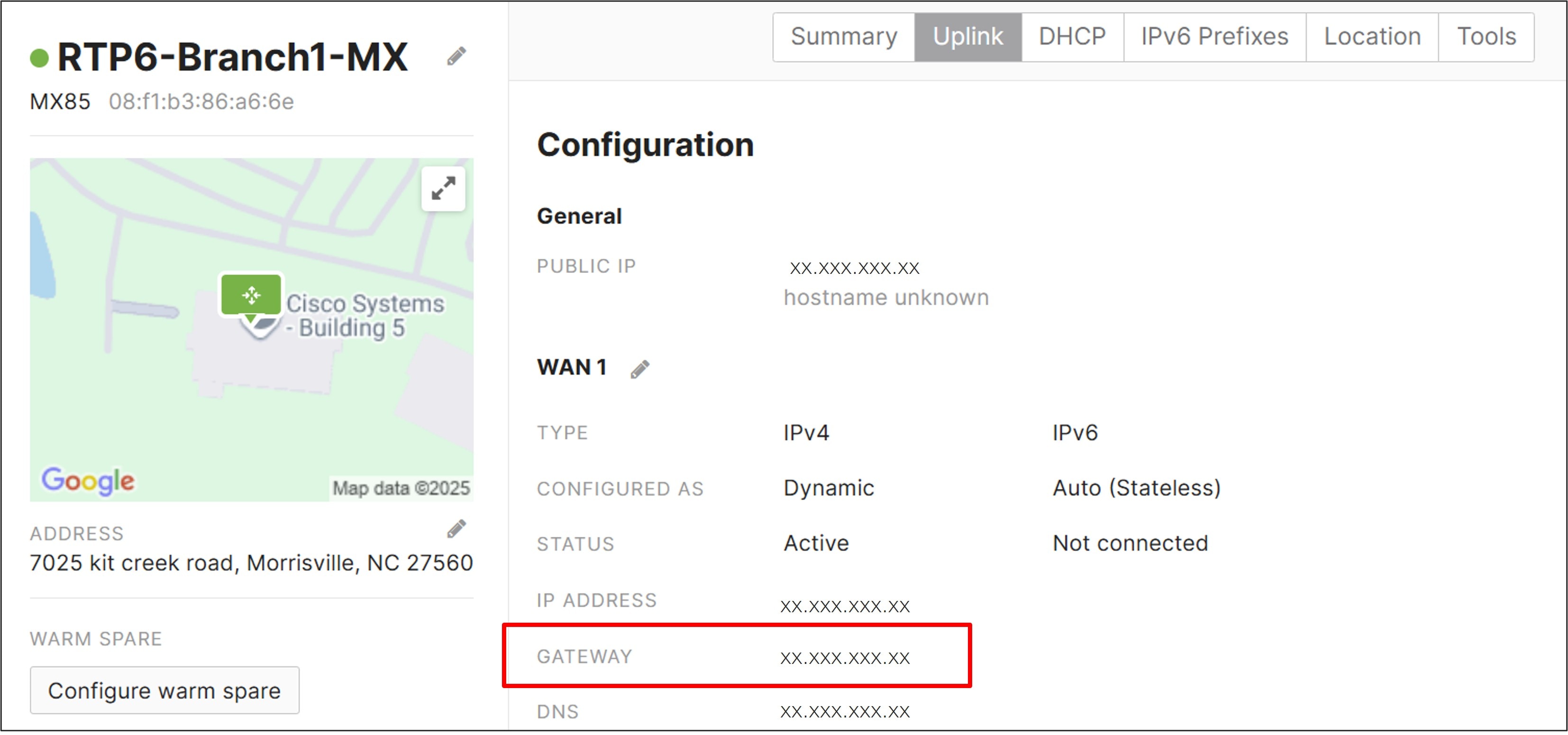
By default, the MX WAN ports are set to receive their IP address, IP gateway, and DNS information through DHCP from the WAN Service Provider (SP). After this information is obtained, the router can connect to the dashboard on the internet for software upgrade, monitoring, and configuration. The WAN interface parameters (static IP address and mask, gateway IP address, and primary/secondary DNS) can also be configured through the device’s local status page if needed for connectivity to the provider. These parameters can also be changed through the dashboard after the device connects.
WAN Uplink dashboard reachability preference
By default, the first WAN interface on the MX router is chosen as the primary WAN interface to establish connectivity to the cloud dashboard when both WAN links are active. If the first link is down, then the second WAN uplink will attempt to connect to the cloud dashboard. The Primary WAN uplink is configurable under the dashboard settings. This link is also the default interface for routed VPN and internet traffic in the absence of traffic steering policies or internet traffic load balancing configuration.
LAN connectivity
Each platform has ports dedicated to LAN connectivity. The LAN interfaces are represented in this table:
Table 11. Secure Router LAN Connectivity
| Secure Router |
LAN interfaces |
Port numbers |
| MX67 |
1x convertible 1 Gigabit Ethernet RJ45 (LAN/WAN) |
Port 2 |
| MX68 |
8 dedicated 1 Gigabit Ethernet RJ45 |
Ports 3 -10 |
| MX75 |
8 dedicated 1 Gigabit Ethernet RJ45 |
Ports 3-10 |
| MX85 |
8x dedicated 1 Gigabit Ethernet RJ45 |
Ports 5-12 |
| MX95/MX105 |
4x dedicated 1 Gigabit Ethernet RJ45 |
Ports 5-8 |
| MX250/MX450 |
8x dedicated 1 Gigabit Ethernet RJ45 |
Ports 3-10 |
| C8455-G2-MX |
8x dedicated 1 Gigabit Ethernet SFP |
Ports 0-7 |
| C8121-G2-MX |
1x convertible 1 Gigabit Ethernet RJ45 (LAN/WAN) |
Port 3 |
The secure router by default is configured for single VLAN (untagged VLAN 1) operation, which is called Single LAN mode. All LAN ports are placed into VLAN 1 and a VLAN 1 layer-3 interface is configured with an IPv4 subnet of 192.168.128.0/24, along with a DHCP server configuration and DHCP pool of addresses in the range of 192.168.128.2 - .254. The purpose of the DHCP pool is to hand out IPv4 addresses to downstream LAN devices (switches, APs, and so on.), allowing them to be quickly and easily onboarded to the dashboard.
When VLAN mode is configured, several VLANs are defined along with their respective layer 3 interface IP addresses that act as IP gateways for downstream clients. When VLAN mode is set for the first time, the Single LAN IP address appears under VLAN 1 (named Default) This VLAN also inherits the DHCP server configuration and DHCP pool for devices in VLAN 1 that request DHCP services.
By default, all secure router ports are enabled and defined as 802.1Q trunks, allowing all VLANs with VLAN 1 as the native/untagged VLAN. In the Unified Branch design, the link to the switch or links to the switch stack are reconfigured to carry only the VLANs defined on the secure router. All unused ports are disabled to reduce security risks. VLAN 1 stays configured as the native/untagged VLAN.
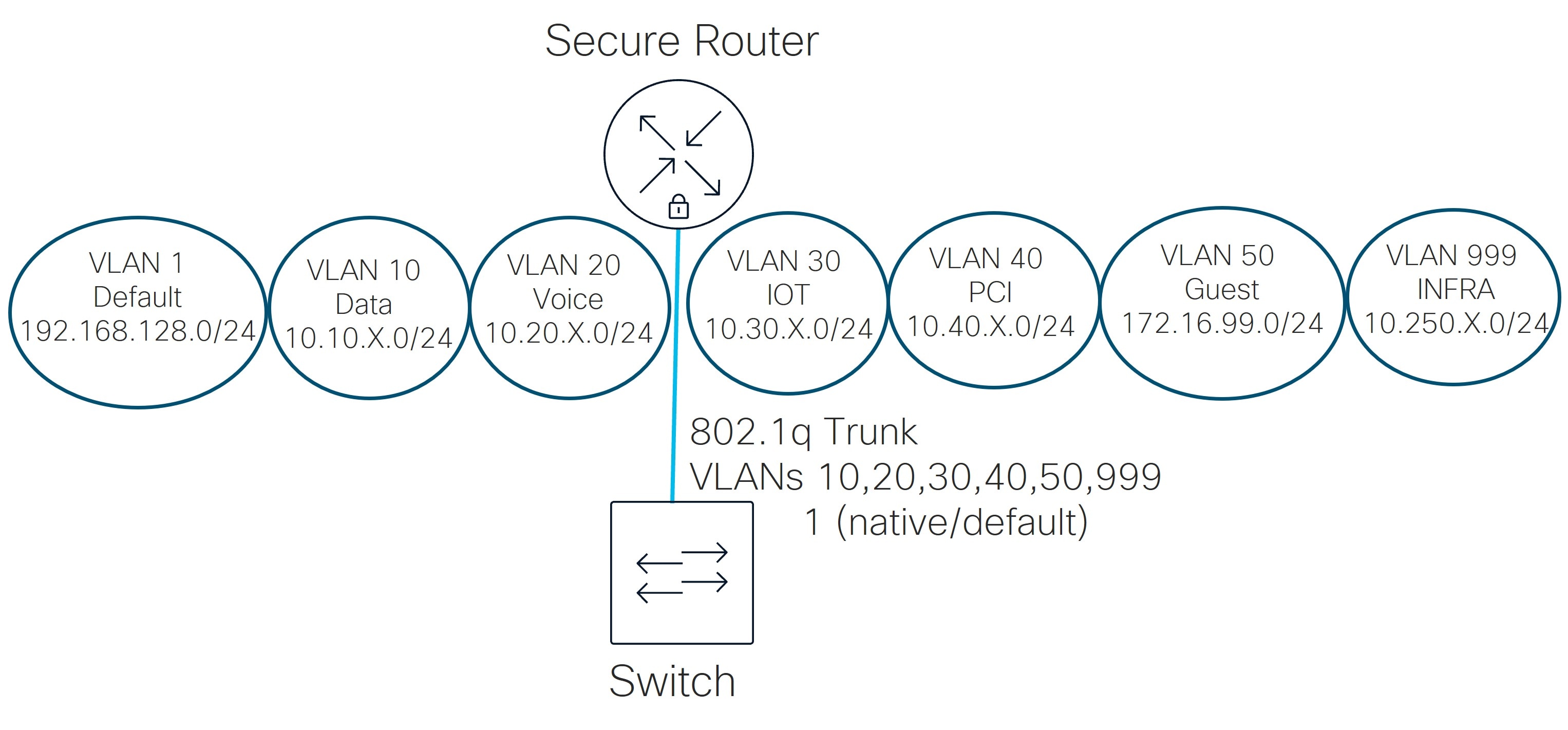
In the small, medium, and large branch designs, 6 additional VLAN interfaces are defined on the secure router in addition to the default VLAN 1, including DATA (VLAN 10), VOICE (VLAN 20), IOT (VLAN 30), PCI (VLAN 40), GUEST (VLAN 50), and INFRA (VLAN 999). VLAN 1 is used for network devices being onboarded onto the network and allowing management traffic to reach the Dashboard. When onboarded, this management traffic is moved into the INFRA VLAN (VLAN 999).
Downstream device dashboard onboarding
When a downstream, connected cloud-managed switch is booted for the first time, all its switch ports default to trunk ports with the native/untagged VLAN defined as 1. The switch initiates an untagged DHCP request on all connected interfaces and receives an IPv4 address in the 192.168.128.2 - .254 address range and gateway address (192.168.128.1) from the router. Likewise, when a downstream cloud-managed wireless AP is connected to the switch and initially booted, the AP initiates an untagged DHCP request for an IP address from the same DHCP pool and gateway on its uplink port. The secure router firewall is, by default, configured to allow all outbound traffic to the internet initiated internally on VLAN 1, and it NATs the traffic to the IP address of the WAN interface. This allows any downstream devices to connect to the dashboard.
Management VLAN
When downstream devices are onboarded by default, their internal management connections are untagged on VLAN 1 and end up sourced with an IP address from the 192.168.128.0/24 pool. This same pool is used as the default for all secure routers in all branches. This allows the devices to connect to the dashboard through the router’s internet uplink, but if the device needs to access shared services in the data center such as radius, DNS, and other services, then a unique subnet needs to be used instead at each branch for these infrastructure devices.
Switches and APs by default try to contact the dashboard on the untagged VLAN, but alternatively, a tagged VLAN can be used under the device configuration settings. In this design, a separate VLAN 999 is created called INFRA and the management control traffic is tagged for that VLAN. After a device is onboarded to VLAN 1 and connected to the dashboard, it can pull its configuration from the dashboard, to begin tagging its management control traffic with VLAN 999. VLAN 999 uses a unique subnet per branch. For ease of operation, most of the network devices use DHCP to obtain a management IP address and establish a management connection to the network. To ensure the devices get the same IP address each time, fixed IP address assignments are used in the VLAN 999 DHCP pool. Automation restrictions prevent static IP address assignments at this time.
Due to automation restrictions at this time, the AP management traffic in this design cannot be directly tagged with VLAN 999. Instead, the switch trunk ports connected to the APs are configured with Native VLAN 999, to put untagged AP management traffic into VLAN 999. Management traffic for all switches within a network is tagged using configuration settings found under Switching > Configure > Switch Settings > VLAN configuration.
To reach the shared services in the data center, the secure router uses the highest VLAN defined and sources the traffic from its IP address in that subnet, which is why VLAN 999 is chosen (so all devices source their management control traffic from the same VLAN). Use the highest VLAN for device management traffic if all devices should use a management IP address from the same subnet.
Secure router high-availability pair
For this phase of Unified Branch, the medium and large branch designs include dual secure routers in a high-availability pair, where one of the routers is active and the other router is in a warm spare configuration. This functionality allows for automatic recovery by activating the spare router if the primary router fails, the primary router’s WAN connectivity tests fail, and/or VRRP heartbeats are not detected on the spare router from the primary router on the LAN. The routers should be connected to each other through downstream switches so VRRP heartbeats from the primary router can be seen by the spare. Configuration is synchronized between the primary and spare routers.
The spare router has its own IP address on each WAN uplink, so it has WAN reachability and dashboard connectivity but is inactive with no data traffic passing through it. The primary router can leverage its own WAN IP address for sourcing VPN traffic, but in this design, a unique virtual IP (VIP) address on each WAN transport (which is part of the WAN transport subnet) is shared between the primary and spare routers to source VPN traffic. Virtual IP addresses reduce failover times if the spare router should become active. Refer to MX Warm Spare – High Availability Pair for more information.
Unified Branch switch
This phase of Unified Branch supports MS130, MS150, C9350, C9200/L/CX, C9300/X/L/LM and -M models of switches to provide LAN connectivity to devices within the branch.
Switch choice and throughput requirements
When choosing a switch model, there are several factors to consider, including number of ports, uplink speeds, stacking capabilities, Power over Ethernet (PoE) capabilities, advanced feature support, and redundant fans and power supplies.
Ensure enough ports are calculated for infrastructure connections, APs, and wired clients and devices. Ensure that the PoE capabilities are adequate for any devices needing power. Also, the aggregate throughput requirements within a branch site should be determined based on the number of clients and each client’s application requirements and traffic expectations, so ensure that the switch upload and download speeds are adequate and can accommodate for future growth.
To view the different switch models, go to the Cisco Cloud-Managed Switching Family Datasheet and the Meraki Sizing Tool. Also check the individual datasheets in Table 4 for information for specifics on interface types, performance capabilities, physical characteristics, power requirements, Power over Ethernet (PoE) capabilities, and so on.
Switch stacks
The small and medium Unified Branch topologies support one switch or switch stack. The large branch topology supports a single switch stack in the layer 2 distribution layer, and one or more switches or switch stacks in the layer 2 access layer.
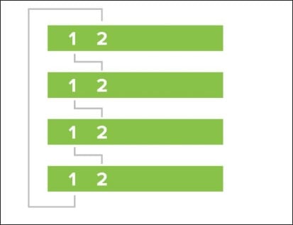
Switch stacking is the process of connecting multiple physical network switches so they operate as a single logical switch, which can operate in either layer 2 or layer 3 mode. The stack behaves as one unified system, simplifying management and increasing network capacity. There are multiple types of stacking: physical stacking, flexible stacking, and StackWise Virtual. Physical stacking is the only stacking supported in the Unified Branch design, and it uses two physical stacking ports on the back of each switch, connected to other switches using stacking cables. Switches are connected in a ring topology, with stack port 1 connected to the neighboring switch’s stack port 2.
At least two and up to eight switches can be configured in a physical stack, and only like-models regardless of port density can be stacked. One exception is the C9300X, which is compatible with C9300 series switches. MS130 switches do not support physical stacking.
To onboard a switch stack to the dashboard, it is recommended to power off the switches, cable them through the stacking cables in a ring topology, connect an uplink from one switch of the stack, then power on the switches.
In this design, two switches in a stack at most can have an uplink to each secure router or to each switch in the distribution layer. This, combined with the stack port connections, provides sufficient redundancy.
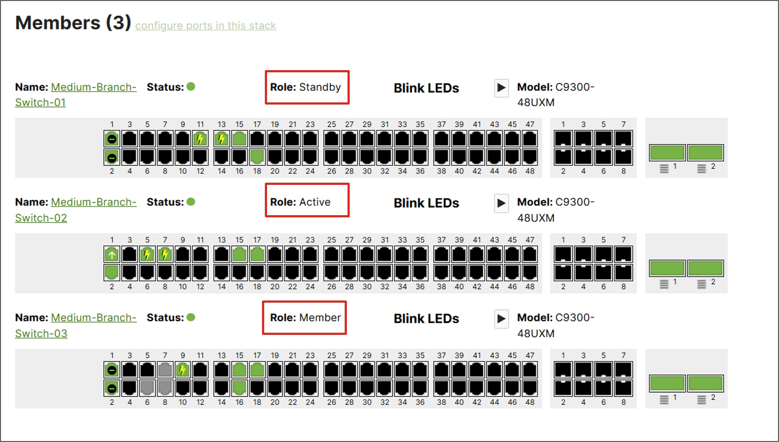
One stack member is elected as the active member. The active member controls and manages the entire stack, handling all configuration, management, and layer 2 or layer 3 protocol operations. The lowest mac address is used to elect the active member if devices are powered on around the same time, otherwise the switch with the highest uptime is the active member. The next switch in line to become the active switch is the member switch. All other switches are labeled as standby switches.
For MS model switches (except for the MS390), each switch in the stack requires its own management IP address. For Catalyst model switches (the C9300 and C9200 switches), the switch stack uses only one single management IP address for the entire stack. For Catalyst switch models running CS code versions, the active member’s burned-in mac address is associated with the management IP address. For Catalyst switch models running IOX XE code versions, a virtual mac address in the form of 0018.0a4f.00xx is associated with the management IP address.
For more switch stack information, go to the Switch Stacks documentation.
Link aggregation
Link aggregation refers to the ability to combine multiple physical Ethernet links into a single logical link which increases bandwidth and provides link redundancy between devices. It is also referred to as EtherChannel, Port Channel, or link bonding or bundling. Up to eight ports can be aggregated into a single logical link, and traffic is hashed across the different links. Layer 2 or Layer 3 links can be aggregated.
Link Aggregation Control Protocol (LACP) is an IEEE networking standard (802.3ad). It allows network devices to negotiate link aggregation automatically, monitoring the status of the links and adjusting the aggregation as needed. Catalyst switches use a strict LACP active implementation. If the connected device is not configured for LACP, the entire link aggregation is suspended. The MS switches use an adaptive LACP implementation. If the connected device is not configured for LACP, the aggregation group is not completely suspended. Instead, one link remains active to prevent device isolation and maintain dashboard connectivity.
Link aggregation requires that ports share similar characteristics such as speed and media type, and that configurations (including VLAN tagging) match on both ends. It is recommended to first configure the downstream device before the upstream switch to avoid outages.
Power over Ethernet (PoE)
Support for PoE on switch ports may be needed when connecting wireless LAN (WLAN) APs, IP phones, surveillance cameras, and other devices to the switch.
Several of the MS, C9200, and C9300 models support 802.3at / PoE+ (Type 2) which can supply up to 30W per port up to the total power budget for PoE devices of the switch. Several C9300 models also support 802.3bt / UPOE (Type 3) which can supply up to 60W per port up to the total power budget for PoE devices of the switch. A few MS models can also support UPOE on a subset of their ports. The total power budget for PoE devices depends on the number of power supplies installed within the switch, as well as the power rating of the individual power supplies (715 Watts AC vs. 1100 Watts AC, and so on.). Refer to the individual data sheets in Table 4 for more details. The Cisco Power Calculator can also be leveraged to determine PoE power consumption for select Cisco models.
Uplink Connectivity to the Secure Router
By default, the switch port uplink connecting to the secure router is configured as an 802.1Q trunk port allowing all VLANs with VLAN 1 being the native/untagged VLAN. In this design, unused or unnecessary VLANs are pruned from the trunks. For example, VLANs 901 and 902 are only used for transport and are not carried on any trunks. In all the branch designs, only the VLANs defined on the secure router are carried on the switch trunks. VLAN 1 remains the native/untagged VLAN and is used as initial onboarding for any new devices added to the network and has access only to the internet (for dashboard connectivity). After a device configuration is downloaded, devices use the INFRA tagged VLAN 999 for management traffic. All unused switch ports defined as Infrastructure, AP, or links to access switches (in the case of the large branch design) are disabled.
Note: Some switches, such as the Catalyst 9200L, only support 512 active VLANs with spanning-tree enabled. VLANs above 512 (VLAN 901, 902, and 999) cannot be added to the configuration until other VLANs have been pruned off all ports. After onboarding the switch or switch stack to the Dashboard, modify the Allowed VLANs trunk configuration on all ports at one time to a subset of VLANs (1, 10, 20, 30, 40, 50, 999) before modifying additional configurations.
The link speed (10 Mbps, 100 Mbps, 1 Gbps, and/or 10 Gbps) and duplex (full or half) of the Ethernet ports on the secure router and the switch must match for the uplink to come up active. The best practice is to leave the link speed for auto-negotiation of speed and duplex.
Unified Branch WLAN APs
The Unified Branch design in this phase supports CW9172, CW9176, and CW9178 models of AP to provide wireless LAN (WLAN) connectivity within the branch. Check the individual data sheets in Table 4 for information for specifics on capabilities, power requirements, and so on.
One or more APs are supported, but the maximum number of APs deployed within the site depends on the requirements of the site. Refer to the High Density Wi-Fi Deployments document for information on capacity planning, site survey, and AP design. To view the different AP models, go to the Meraki Wireless Cloud-Managed Access Points Family Datasheet and the Meraki Sizing Tool.
AP throughput requirements
The aggregate throughput requirements of each AP within a branch site should be determined based on the number of clients and each client’s application requirements and traffic expectations and ensure that uplink speeds to the switch are adequate and can accommodate for future growth.
Uplink connectivity to the switch
The CW9176 and CW9172 APs support a single uplink port for connectivity to the switch or switch stack. The CW9178 AP supports dual uplink ports for connectivity to the switch or switch stack which can be combined for link aggregation supporting up to 10 Gbps.
By default, the AP uplink connecting to the switch is configured as an 802.1Q trunk port allowing all VLANs with VLAN 1 being the native/untagged VLAN. As mentioned previously, VLAN 1 is the default/untagged VLAN on the switches to ensure downstream switches and APs can initially connect to the dashboard to onboard, but the device management is moved into the tagged INFRA VLAN 999 after configurations are downloaded.
Note: Due to automation restrictions with Branch as Code at this time, the native/untagged VLAN on the switch trunks to each AP is configured as VLAN 999 so AP management traffic can move into VLAN 999.
Since the AP services both corporate and guest users in different VLANs, the connection between the AP and switch should be configured as a trunk port. In this design, unused VLANs are pruned from the trunk.
As with the uplink between the secure router and the switch port, link speed and duplex (full or half) of the Ethernet ports on the switch and the AP must match for the uplink to come up active. Again, the best practice is to typically leave the link speed for auto-negotiation of speed and duplex.
Table 12. AP LAN Uplink Interfaces
| Access Point Model |
LAN Uplink Interfaces |
| CW9172I/CW9172H |
1x 100M / 1G / 2.5G BASE-T Ethernet (RJ45) |
| CW9176I/DI |
1x 100M / 1G / 2.5G / 5G / 10G BASE-T Ethernet (RJ45) |
| CW9178I |
2x 100M / 1G / 2.5G / 5G / 10G Base-T Ethernet (RJ45) |
PoE requirements for APs
When configuring the uplink between the switch and APs, the network administrator needs to consider how power is to be supplied to the APs. Power can be supplied via a switch that supports PoE and supplies the necessary power (in terms of Watts) required for the AP model, or through an external device such as a power supply or inline PoE injector. To ensure the power is sufficient to power the AP, check the individual AP data sheets in Table 4 for minimum and maximum power requirements.
Some APs require higher power levels in order to offer all features and functionality. If switches or power injectors cannot supply those power levels, then the AP can run in “low power mode”. When in low power mode, the AP will disable some of its functionality, such as its Air Marshal radio and some of its transmit streams on the 2.4 GHz band. Refer to the individual datasheet in Table 4 for AP functionality at each power level. CDP or LLDP is used to negotiate PoE+ energy levels but both CDP and LLDP must be used when requesting PoE++ energy levels. If LLDP is disabled, only PoE+ energy levels can be negotiated. By default, Dashboard-ready devices have CDP and LLDP turned on by default. Refer to Low Power Mode and PoE Negotiation for more information.
Unified Branch services
Multiple services are included in this phase of Unified Branch, such as WAN services, wired LAN services, wireless LAN services, security services, and network management services.
WAN services
Secure WAN services are implemented by the secure router. This includes Software-defined WAN (SD-WAN) and its features, such as secure WAN connectivity, LAN to WAN routing, and traffic shaping.
Software-defined WAN (SD-WAN) is a set of features that enables networks to automatically adapt to changing WAN conditions without manual intervention, ensuring optimal performance for critical applications and minimizing disruptions for sensitive traffic like VoIP. It also offers secure, granular traffic control and is often a more scalable and cost-effective solution compared to traditional WAN circuits such as MPLS. SD-WAN makes use of the Auto VPN feature, which is a proprietary technology that facilitates route advertisements and allows VPN tunnels to be easily built between WAN routers in the network branches.
WAN connectivity
WAN connectivity refers to the wide area network’s topology and how the router connects to it. The router in a branch typically connects directly to the service provider, obtains a dynamic IP address by default, and receives a gateway address and DNS server address through DHCP. Traffic from the branch router is sent towards the service provider to connect to the dashboard, to route internet traffic, or to route encrypted VPN tunnel traffic to another branch site.
Note: IP addresses, gateways, and DNS server addresses can also be statically defined as an alternative to DHCP.
This design uses DHCP on both transports to obtain IP addresses, gateways, and DNS server addresses.
WAN topology
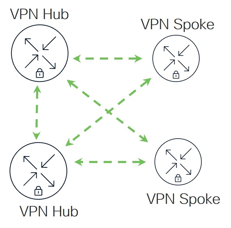
A WAN topology refers to the different ways that a Wide Area Network can connect to multiple locations, such as full mesh, hub-and-spoke, and partial mesh. The Unified Branch design implements the hub-and-spoke topology, where all branch sites (spokes) set up direct VPN tunnels to a central hub or multiple hubs.
A hub is defined as a central site, such as headquarter locations, data centers, and large campuses that is hosted near resources and services that other locations need to access. Hubs also set up direct VPN tunnels to other hubs. All spoke-to-spoke communication must traverse the hub.
This model simplifies management and traffic flow and is cost-effective because only hubs need to have the capacity to scale the number of VPN tunnels required. However, it introduces additional latency as all traffic must pass through the hub, which could also become a congestion point if not properly designed. For proper redundancy, ensure that more than one hub is defined.
When configuring spokes in a hub-and-spoke VPN topology, the spokes must have the hubs explicitly listed or configured as peers to establish tunnels. Before hubs can be chosen in the drop-down menu in the spoke configuration, they must have first been defined as a hub in their own configuration. In what order the hub is listed determines the hub priority for that spoke. When a route is available through multiple hubs, the spoke routes to the hub highest on the list.
In this design, two hubs are defined with DC1 as primary and DC2 as backup.
Auto VPN
Auto VPN is a proprietary technology that automatically builds encrypted VPN tunnels between WAN routers in the network branches. The main mechanism that allows Auto VPN to happen is the VPN registry, which is a cloud service that keeps track of contact information for the WAN routers participating in Auto VPN for an organization. Routing across the secured WAN leverages the contact information found in the VPN registry. It is important that certain IP addresses and ports are open on any upstream firewalls so WAN routers can reach the VPN registry. Refer to Auto VPN Configuration and Troubleshooting for more information.
Dual WAN
In this design, dual WAN transports are implemented, both of which have connectivity to the dashboard. Dual WAN uplink provisioning to separate service providers is a general best practice for resiliency purposes so when a connection to one transport or provider fails, there is still connectivity for traffic through the opposite transport or provider. Connection monitoring is performed on each WAN uplink interface when carrier is detected and an IP address is assigned (static or dynamic), which can determine the health of the uplink and internet connectivity and determine when failover needs to take place. Refer to the Connection Monitoring Test Process page for more information.
By default, control connectivity to the dashboard leverages the first WAN (WAN 1) but will leverage the second WAN (WAN 2) if the first WAN uplink connectivity fails. The primary WAN uplink can be configured through the dashboard and is also the default interface for routed VPN and internet traffic in the absence of traffic steering policies or internet traffic load balancing configuration.
With dual uplink solutions, VPN tunnels can run over both available uplinks or when the primary link fails. This design utilizes VPN tunnels over both uplinks.
Dual WAN can be implemented as active/standby or active/active. With active/standby, all traffic (VPN and internet) is directed out WAN 1 and falls back to WAN 2 when WAN 1 fails. With active/active, both uplinks are available for traffic forwarding. In active/active mode, internet traffic and VPN traffic can use traffic steering to direct some traffic out one link or the other, but there is also the ability to load-balance internet traffic.
This design implements dual WAN as active/active. Some VPN and internet traffic is directed out of the second WAN transport with traffic steering policies, and all other traffic is directed out of the first WAN transport by default.
With load balancing, internet-bound traffic flows are distributed between the two uplinks. How the load is distributed between the WAN 1 and WAN 2 links depends on the bandwidth configured under the Uplink configuration. The link with the higher configured bandwidth distributes more flows. Load balancing is based on flows considering source and destination IP and port and will attempt to round-robin connections on both WAN uplinks.
Some applications spawn off multiple sessions for a single use session which could get load-balanced to the opposite WAN uplinks with different NAT addressing. This can cause application failures. Disable load-balancing in those cases and use traffic steering policies to distribute traffic to the WAN uplinks.
This design does not implement load-balancing for internet-bound traffic.
LAN to WAN routing
Auto VPN through the VPN registry populates the routing table of subnets which belong to other sites. For a VLAN subnet to be advertised, its VPN mode setting is set to Enabled in the dashboard configuration. For VLAN subnets that should not be advertised, their VPN mode setting is set to Disabled (the default). In this design, the default VLAN 1 and Guest VLAN 50 subnets are set to disabled, while all other VLANs are set to enabled.
When client traffic needs to be routed, the routing table is consulted for the destination for the longest-match prefix. If the route exists in the table, then the traffic is routed according to the next hop. The route could be a connected or static route, client VPN and other VPN peer route, Auto VPN route (where traffic will be directed over the VPN tunnel to a particular site), or BGP-learned route. Given the same route, one route type is selected depending on the priority. Refer to the MX Routing Behavior document for more information. Connected, static, and Auto VPN routes are supported in the Unified Branch design.
If a specific Auto VPN route has multiple next hops to its hubs after the longest-match prefix is selected, then the router will choose to route to the hub with the highest priority. This priority is established through the order in which the hubs are defined on the spoke’s Site-to-site VPN page on the dashboard.
Default route advertisement
There are multiple ways for default routes to be defined for a secure router. By default, default routes are always installed using the WAN uplinks as the next hop out to the internet. If no other default routes are defined, traffic will take the default route directly to the internet if it doesn’t match a route in the Auto VPN overlay.
A default route can also be configured from a hub when the hub is defined on the spoke’s Site-to-site VPN configuration page. Next to the hub definition, an IPv4 default route box can be checked. This default route takes precedence over an uplink default route. This means that all traffic not matching other VPN routes, which includes internet traffic, takes the overlay to the hub advertising the default route and is routed from there. If multiple hubs advertise the default route, then the router will choose to route to the hub with the highest priority.

Another way to advertise a default route from the hub is to add a static default route and enable it for VPN mode or advertise it from the hub through BGP. A default route can also be installed on the branch through the configuration of Cisco Secure Access tunnels.
The routing table on the branch router can be viewed under Monitor > Route Table on the dashboard.
In the first phase of the Unified Branch design, default routes are advertised from each hub using the IPv4 default route checkbox configuration on the spoke’s Site-to-site VPN configuration page. In this current phase of the design, Cisco Secure Access is deployed, and a default route is installed to the Cisco Secure Access tunnels. To leverage the Cisco Secure Access tunnels, the IPv4 default route checkbox next to the hub on the spoke’s Site-to-site VPN configuration page must not be checked since the default route to the hub takes precedence.
Direct Internet Access (Local Internet Breakout)
By default, if there are no default routes advertised from the hub sites or installed due to Cisco Secure Access tunnels, traffic can be sent out direct internet access (DIA) from the branch using the WAN uplink if there are no matches to routes already in the routing table. When a default route is advertised from the hub sites or installed due to Cisco Secure Access tunnels, this puts the branch in full tunnel mode which means all traffic is now tunneled, including internet traffic. The exception to this is for any VLAN subnet with VPN mode disabled, which means the subnet is not advertised across the Auto VPN. This traffic is also not transmitted across the VPN and can only be transmitted out the direct internet uplink, unless prohibited by firewall rules.
If direct internet access is needed while in full tunnel mode, VPN exclusions must be configured. This allows the administrator to configure layer-3 and some layer-7 destination rules to determine exceptions to the full tunnel VPN configuration, allowing some traffic to go out to the internet directly.
DIA improves the user experience since it eliminates any performance degradation related to backhauling internet traffic to a centralized data center.
In this design, some SaaS traffic for corporate users and dashboard traffic for downstream switch and AP devices leverage VPN exclusions.
SD-WAN traffic policies
SD-WAN traffic policies match traffic and steer traffic to a particular uplink and failover to the opposite uplink should the preferred one fail or if SLAs are not met for performance. Rule definitions for classifying/matching traffic are based on L3 characteristics (source and/or destination IP address and/or port) or L7 characteristics (application and/or application category). If a policy is contingent on performance, it references a previously configured performance class. Performance classes are configured to define the max loss, latency, and jitter a traffic class can tolerate. SD-WAN policies are defined separately for internet and VPN traffic.
For VPN traffic, performance probes (UDP data of approximately 100 bytes) are sent every second and are used to determine loss, latency, and jitter over each Auto VPN tunnel. For internet data, uplink statistics are gathered. The default target is 8.8.8.8 (Google DNS), but it can be modified from the dashboard under Security & SD-WAN > Configure > SD-WAN & traffic shaping > Uplink configuration > Uplink statistics.
Note: All traffic not matching a defined policy is routed to the default WAN uplink until it is declared down, regardless of loss, latency, or jitter. It is recommended to define a default traffic policy with a default performance class to catch all other traffic not already specified in policy to avoid traffic being transported across a poor-performing tunnel.
In this design, both internet traffic and VPN traffic steering policies were created. Custom performance classes were defined for SaaS traffic, critical application traffic, and default VPN traffic.
WAN traffic shaping
On the secure router, uplink bandwidth settings, both upload and download bandwidth, can be set. These values are used for rate-limiting all traffic in and out through each WAN port. This is used when the contracted bandwidth for the WAN service (the sub-line rate) is less than the physical bandwidth of the connection. Bandwidth limits can even be set on each client device’s total incoming/outgoing traffic.
There are also shaping policies that can be applied on a per user per-application basis. Applications or custom expressions (CIDR/IP ranges, ports, local networks, and so on) can be used to match traffic, then bandwidth limits (optionally), priority, and DSCP tags can be assigned. Priorities can be set to High, Normal, or Low and allow the secure router to prioritize a given network flow relative to the rest of the network traffic. Expedited Forwarding traffic (DSCP 46) is given highest priority. Default shaping rules can be used with additional rules added, or rules can be completely customized.
For more information, refer to the SD-WAN and Traffic Shaping document.
In this design, uplink bandwidth setting examples are provided. Also, default shaping rules are used with additional rule examples for guest and critical application traffic.
Wired LAN services
Some wired LAN services are implemented by the secure router, some by the switch, and some by both. These services include LAN connectivity, Link Layer Discovery Protocol (LLDP), VLAN segmentation, Spanning Tree Protocol, STP Guard, storm control, access policies, shared services VLAN, LAN Routing, DHCP, and LAN Switch QoS (ingress classification, marking, and queuing).
LAN connectivity
For LAN connectivity, there are 802.1Q trunks between the secure router, switches, and APs to carry VLAN-tagged traffic as well as native/untagged VLAN 1 traffic. Ports on the network devices are set to auto-negotiate port speed and duplex as a general best practice unless there is a specific reason otherwise.
Link Layer Discovery Protocol (LLDP)
LLDP is a layer-2 protocol that automatically discovers connected devices. It is used to identify devices and their capabilities on the network, inform VoIP devices of the voice tagged VLAN, and negotiate PoE capabilities. LLDP is turned on by default.
VLAN segmentation
VLAN segmentation provides a way to partition the network into different broadcast domains, each with a separate subnet. Data packets can be tagged with a VLAN identifier (VLAN ID) and switches can use tags to only forward between ports that share the same VLAN ID. Access ports assign incoming untagged traffic to a VLAN based on the port configuration, and trunk ports can carry all tagged VLAN traffic, as well as untagged traffic that is assigned to the native VLAN defined on the trunk. To communicate with devices in other VLANs, traffic needs to be forwarded to a layer-3 device that can route between VLANs.
In the Unified Branch design, the router provides the layer 3 termination point (SVIs) for all network VLANs, and by default, allows routing between those VLANs. In this design, the router is configured for seven different VLANs: Default (VLAN 1), Data (VLAN 10), Voice (VLAN 20), IOT (VLAN 30), PCI (VLAN 40), Guest (VLAN 50) and INFRA (VLAN 999). VLANs 1, 10, 20, 30, 40, 50, and 999 are carried on the trunk port between the router and switch, and VLAN 1 is the native or default VLAN for any untagged traffic coming in.
To prevent inter-VLAN communication, firewall rules can be added on the secure router. To prevent subnets from being advertised and traffic from being routed across the VPN network, subnets are Disabled for VPN mode in the dashboard. For example, the Guest and Default subnets are Disabled as their traffic should not traverse the VPN tunnel network. It is assumed that the Guest and Default VLAN traffic will have direct internet access only and may be further restricted based on security policies implemented on the secure router. The rest of the subnets are Enabled for VPN mode and advertised to other WAN routers through the VPN registry.
Spanning tree protocol
Spanning tree is a network protocol designed for Ethernet networks to prevent bridge loops and broadcast storms that result from them. It operates at layer 2 (the Data Link Layer) of the OSI model. Rapid Spanning Tree Protocol (RSTP) is an enhanced version of the original protocol, providing faster convergence times after network topology changes or link failures. Multiple Spanning Tree Protocol (MSTP) extends RSTP to allow multiple spanning tree instances to be created over the same physical network; it enables the creation of separate spanning tree instances for different groups of VLANs. MS switches support only RSTP, and Catalyst switches support MSTP but are not configurable for more than one instance at this time. MSTP is fully compatible with RSTP – MSTP BPDU’s can be interpreted by RSTP bridges as RSTP BPDUs.
On the switches, RSTP or MSTP is enabled by default and will be active on all switches in the current network. Access ports on link up will bypass the learning state and immediately go into a forwarding state. It is critical that spanning-tree remains enabled to protect from unintended loops in the network. It’s also best practice to choose and configure the root switch and backup root switches, which are typically in the core or distribution layers. In the small and medium branches, the single switch or switch stack can be configured with a bridge priority of 4096 to make it the root switch or switch stack. Using 4096 as the bridge priority instead of 0 provides flexibility to make temporary modifications to the root bridge if necessary. The default bridge priority is 32768. In the large branch, the distribution layer switch stack is configured with a bridge priority of 4096, and any access switches are configured as backup root switches with a bridge priority of 8192.
After spanning tree is enabled globally, it is enabled at the port level by default. It is recommended that spanning tree be enabled on all ports. It is important to note that the secure router does not run spanning tree and will not exchange BPDUs with other switches nor participate in the root bridge election process. If the secure router receives BPDUs on the LAN, these BPDUs are re-forwarded to other ports within the same VLAN, or broadcast domain.
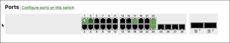
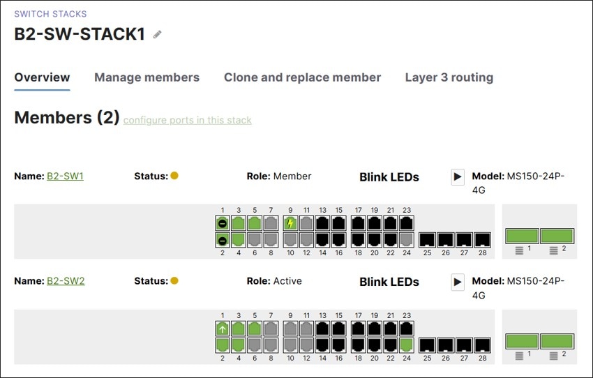
Spanning-tree blocked ports
In the small branch design with a switch stack, it is normal to see spanning-tree blocking on the uplink port to the secure router on the member (not active) switch. All uplink ports on the active switch are forwarding.
In the medium branch with a switch stack, it is normal to see spanning-tree blocking on both uplink ports to the secure routers on the member (not active) switch. All uplink ports on the active switch are forwarding, although the spare router is not actively forwarding data traffic but still receives VRRP heartbeats through the forwarding port.
In the large branch, the distribution switch stack ports spanning-tree states are similar in the medium branch topology. It is normal to see spanning-tree blocking on both uplink ports to the secure routers on the member (not active) switch. All ports on the active switch are forwarding. The access switches are forwarding on all uplinks since their redundant links have been grouped into aggregate links. Without aggregation, one of these uplinks would be blocked due to spanning-tree.
STP guard
STP guard is a configuration option under the switch port or switch port profile. Settings include Disabled, Root guard, BPDU guard, or Loop guard. STP Guard is disabled by default.
In this design, only BPDU guard is configured. This configuration protects the spanning tree topology by enforcing the STP domain borders. The port moves into a disabled state if it receives a BPDU. This should be applied to access ports connected to clients and trunk ports connected to APs. Do not apply to the uplink trunk ports connecting the switch to the secure routers or on any trunk ports connecting to switch or switch stacks.
Unidirectional Link Detection (UDLD)
UDLD detects and acts on logical one-way links to prevent forwarding loops and blackholing of traffic. It is supported on switches and configured under a port or port profile. The Alert only setting (default) generates an alert if UDLD detects one-way traffic. The Enforce setting blocks network traffic if UDLD detects one-way traffic. Enforce is recommended to be used on point-to-point links between switches.
This design uses the Alert only setting for UDLD on all ports.
Storm control
Storm control is designed to prevent network performance degradation caused by a network storm of excessive broadcast or multicast traffic. It can be enabled on switches to suppress broadcast, multicast, and unknown unicast packets based on a traffic percentage on an interface. Each category of traffic bandwidth is monitored on each switch port every second. Traffic that exceeds the defined limit is dropped.
To set the percentage of broadcast, multicast, and unknown unicast traffic, the administrator needs to understand what the normal level of broadcast, multicast, and unknown unicast traffic is in the network. This will vary from network to network and may depend on the day of the week and even the time of day.
In this design, an example storm control policy is created.
Access policies for port access
Access policies can be configured on the switch, which require authentication from a RADIUS server before network access is granted. These are commonly configured on access-layer switch ports to prevent unauthorized devices or users from connecting to the network. RADIUS servers can pass back dynamic VLAN information the client belongs to and well as other information (such as SGT tags), and the client can then obtain IP address information through DHCP.
The RADIUS server can be the built-in RADIUS server from the dashboard or a standalone server in the network.
There are three access policy types:
● 802.1x: Clients that connect are prompted for their credentials. If credentials are valid, their device can be granted access to the network.
● MAC Authentication Bypass (MAB): When MAB is enabled, the client’s MAC address is authenticated against a RADIUS server. If the server determines the MAC address is a valid credential, the device will be allowed access.
● Hybrid Authentication: With hybrid authentication, clients are prompted for their credentials for 802.1x authentication, but if the client doesn’t start 802.1x authentication then the client’s MAC address will be authenticated with the RADIUS server. Hybrid authentication is useful when not every device supports 802.1x authentication, however, MAB is less secure and more easily spoofed.
Host mode for 802.1x refers to how many clients can be authenticated and connected through a single port, and there are 4 different settings. Single-host allows only one client per port. Multi-host allows multiple clients, and one successful authentication grants access to all clients on that port. Multi-auth allows multiple clients but each authenticates separately. Multi-domain requires separate authentication for voice and data devices on the same port.
In this design, a RADIUS server in the data center is leveraged. The access policies are applied to client ports using hybrid authentication and set for multi-auth mode. No failed Auth VLANs are defined if authentication fails.
Shared services VLAN
A shared services VLAN is designated to host network services that can be leveraged by other VLANs. Its purpose is to centralize, secure, and efficiently manage common network services that are utilized by other VLANs. In a local branch, a shared services VLAN might contain shared resources such as local printers or file servers that do not need to reside at a data center or central site. To allow certain traffic or restrict certain traffic to this VLAN locally, layer-3 and layer-7 firewall rules can be added to the secure router.
In the data center, shared services could be DHCP, DNS, RADIUS, syslog, NetFlow, and so on. VLANs with devices that need to reach shared services in the data center need to have their VPN mode enabled so their subnet can be reachable from the data center. To allow certain traffic or restrict certain traffic across the Auto VPN overlay, site-to-site firewall rules can be added to the secure router.
This design doesn’t leverage a shared services VLAN but uses local firewall to allow access to a subset of resources in a local branch VLAN, and VPN firewall rules to allow access to a subset of resources in the data center.
LAN routing
In the Unified Branch design, the secure router is configured for layer-3 routing with Switched Virtual Interfaces (SVIs), meaning the routing to the LAN is through the directly connected VLAN interfaces (connected routes).
Static routing is also supported in this release. Static routes are used so traffic can be routed to other subnets reachable through another layer 3 device on the network. Each static route requires a next hop IP address defined that is included within the scope of a configured VLAN/subnet so traffic can be routed successfully. When a static route is added to the secure router, it can optionally be enabled for VPN mode so it can be advertised to other sites.
Dynamic Host Configuration Protocol (DHCP)
DHCP is a network protocol used on IP networks and automates address assignment and other network configuration parameters to devices to allow them to communicate on the network. It reduces manual workload for network administrators, minimizes errors, and allows new devices to be added quickly or moved to other network segments without manual intervention.
In the Unified Branch design, the secure router can act as a DHCP server, or it can forward DHCP messages to a centralized server, commonly located in a data center. As a DHCP server, lease time is configurable up to a week, boot options and DHCP options and DNS servers can be specified, and reserved ranges and fixed IP assignments can be configured. Mandatory DHCP is also configurable, and if enabled, client traffic without DHCP leases (ex. static IP addresses) will be dropped. DHCP settings are set for each VLAN that has a layer-3 interface on the router.
In this design, the Default VLAN, GUEST VLAN, and INFRA VLAN use local DHCP services from the secure router, while the other VLANs get relayed by the secure router to a DHCP server positioned in the data center. The Default VLAN and GUEST VLAN receive OpenDNS IP addresses on the internet to use for DNS, while the other VLANs receive DNS server information in the data center. For the INFRA VLAN, fixed IP assignments are created for the switches and AP, so their IP addresses stay the same and no static IP address configuration is required.
LAN switch Quality of Service (QoS)
QoS allows for prioritization of traffic in the network. It guarantees some fraction of the link to each configured priority level when there is congestion on the link. Higher priority queues receive more bandwidth than those in lower priority queues, but bandwidth can be used by other queues when there is no congestion.
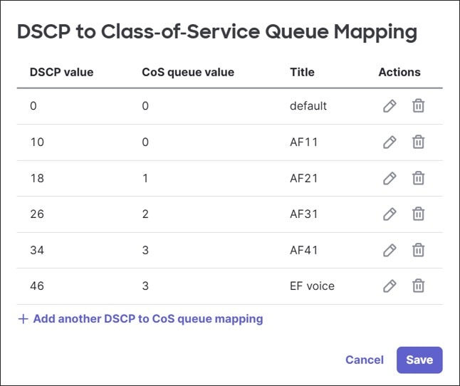
Differentiated Services Code Point (DSCP) bits in the packet header inform switches what Class-of-service (CoS) queue should be used through a DSCP-to-CoS queue mapping policy table that can be modified.
DSCP bits can be added, modified, or trusted for a particular packet. The switches use QoS network rules matching on VLAN, protocol, source port or destination port to define how to handle DSCP tagging of packets.
By default, DSCP tags are trusted and passed through unmodified, and default DSCP-to-CoS settings are used to determine what outgoing queue packets will use. An incoming packet with DSCP set that does not match a QoS rule will keep the DSCP setting, and if a packet’s DSCP does not match the DSCP-to-CoS mapping, it is placed into the default queue.
Note: Switch QoS settings are network-wide settings, so all switches sharing a network inherit the same settings. Refer to MS Switch Quality of Service Defined for more information.
In this design, the DSCP-to-CoS mappings were kept at default. Guest traffic is set to untrusted and get assigned DSCP 0, while other traffic is set to trust DSCP values.
Wireless LAN services
Wireless LAN (WLAN) services consist of configuration related to wireless LAN clients. The services consist of wireless connectivity, support for multiple SSIDs, guest services, RF profiles with radio resource management (Auto RF and AI-RRM), and wireless QoS.
Wireless connectivity
Wireless LAN connectivity is provided through Wi-Fi 7 / 802.11be compliant CW9172, CW9176, and/or CW9178 cloud-managed APs which function as gateways that bridge wireless LAN clients onto the wired LAN as well as provide connectivity between WLAN clients where desired. In bridge mode, wireless LAN clients receive IP addresses either from centralized DHCP servers or from DHCP pools defined on the secure router.
In this design, guest clients receive IP addresses from a local pool defined on the secure router, while the corporate clients receive IP addresses from a centralized DHCP server in the data center.
Multiple SSIDs
Multiple SSIDs can be configured to provide different services and levels of security within the branch deployment. For example, an SSID targeted for employee traffic can be configured 802.1X authentication using an external Radius server, operating in WPA3 transition mode.
In this mode, wireless clients that support both WPA3 - the latest Wi-Fi security protocol – can connect to the SSID using the 2.4, 5, or 6 GHz bands. Additionally, wireless clients that support only WPA2 can connect to the same SSID using only the 2.4 or 5 GHz bands.
Rather than provisioning multiple SSIDs for data, voice, and IoT devices, the RADIUS server can leverage group policy configured through the dashboard to assign the VLAN which the client traffic is to be terminated based on its identity, learned via username/password, digital certificate, or MAC address / MAB. This reduces the number of SSIDs broadcast within the branch.
Alternatively, for IoT devices, another SSID configured for pre-shared key (PSK) authentication, operating in WPA2 mode may be provisioned to alleviate the burden of maintaining MAC address lists.
In this design, one guest and one corporate SSID are configured. Within the corporate SSID, 802.1x authentication and WPA3 transition mode are enabled. After the client authenticates, a group policy name is passed back from the RADIUS server which references a VLAN to assign for the client traffic. SGT tags are not set in this policy name, as that would require more policies to be defined. Instead, a separate SGT tag is passed back from the RADIUS server.
Note: Wi-Fi 7 cannot be enabled in the corporate SSID until per-group SSID configuration is supported because the guest SSID, which resides on the same AP, does not meet the security standards necessary.
Per-group SSID configuration is available starting in MR release 32.1.4, where Wi-Fi 7-compliant SSIDs can co-exist on the same AP as non-Wi-Fi 7-compliant SSIDs as long as they are in separate SSID groups. SSIDs are grouped into 4 SSIDs per group, for a total of 4 groups:
● Group 1: SSID 1 to 4
● Group 2: SSID 5 to 8
● Group 3: SSID 9 to 12
● Group 4: SSID 13 to 15
Wi-Fi 7 is not yet included in this design because the per-group SSID feature is still in BETA at the time of this writing. To accommodate a future move to the per-group SSID feature, the Corporate and Guest SSID’s should be defined in separate SSID groupings. For example, the Guest SSID is defined in SSID 1 and the Corporate SSID is defined in SSID 5. For more information, go to the WPA3 Encryption and Configuration Guide.
Guest services
To support wireless guest services, a separate SSID may be provisioned within the branch. There are multiple methods for provisioning guest wireless access, from self-registration portals to requiring an internal sponsor within the organization. The most basic wireless guest access consists of an open SSID mapped to a VLAN, with a simple click-through splash page.
Guests may be allowed access to the internet only, optionally with the ability to restrict the content to which they are allowed to access through the content filtering and next-gen firewall capabilities of the secure router. There is also a setting to enable layer-2 LAN isolation where clients can only communicate with their IP gateway and not to other clients within the SSID.
In this design, a separate guest SSD is provisioned using an open SSID mapped to a VLAN with a simple click-through splash page. Guests are allowed only access to the internet with layer-2 isolation enabled.
SSID availability
With this feature, the administrator can specify certain times of day that an SSID is available on a particular access point. When enabled, an existing schedule template can be chosen, or a custom schedule can be created.
In this design, a custom schedule is created.
RF profiles with Radio Resource Management (Auto RM and AI RRM)
The dashboard provides pre-configured RF profiles for ease of deployment. For the Unified Branch design, a single RF profile is used. The Basic Indoor Profile can be used directly or copied first then modified as needed to meet the requirements of branch. The RF profile controls various settings including RF bands (2.4, 5, & 6 GHz) enabled within the branch - either on a per AP, or per SSID basis, minimum bit rate configurations - either on a per band or per SSID basis, minimum and maximum transmission power or the radios within each band, as well as channel width, among other functions. Band steering is also an option which steers capable clients to use the higher frequencies to leave lower frequencies available for legacy clients. The best practice is to allow radio resource management (RRM) and AI-RRM to leverage the RF profile to optimize the RF environment for wireless client devices.
In this design, the corporate SSID is enabled for 2.4 GHz, 5 GHz, 6 GHz, as well as band steering. The guest SSID is enabled for 2.4 GHz and 5 GHz. Default settings were mostly chosen.
Wireless QoS
Cloud managed APs support per-user and per-SSID bandwidth shaping in the upstream and/or downstream direction. For SSIDs with employee traffic (such as the Corp SSID) there may be no need or desire to limit traffic. However, there may be a desire to limit traffic on the Guest SSID, so that it consumes only a certain amount of bandwidth on the wireless medium as well as on the internet WAN connection. This can be accomplished through per-client and per-SSID bandwidth shaping configuration within the dashboard.
Note: This can only be enforced on a per-AP basis.
In addition to bandwidth shaping, cloud-managed APs also support traffic shaping. Traffic shaping provides the ability to identify traffic based on custom rule definitions specifying HTTP hostnames, port number, IP address range, or combinations of IP address range and port; or based on pre-defined Layer 7 application categories. After categorization, rule actions control shaping and/or prioritization of the traffic by allowing unlimited bandwidth usage (ignoring bandwidth shaping limits set for the SSID), obeying the SSID limits set for the SSID, or applying more restrictive limits than specified for the SSID. The cloud dashboard provides a default set of rules for ease of deployment, which can be enabled or disabled.
In terms of QoS classification & marking traffic, cloud-managed APs implement a default downstream mapping of DSCP value to 802.11 access categories found at this URL: https://documentation.meraki.com/MR/Wi-Fi_Basics_and_Best_Practices/Wireless_QoS_and_Fast_Lane
In the upstream direction, QoS sent by the client is honored. The DSCP field within the traffic sent from the client is maintained on the Ethernet network.
In this design, both guest and corporate SSIDs leverage default shaping rules. Only guest traffic utilizes the per-client and per-SSID bandwidth limit settings.
Security services
Security is already built into different layers of the branch and across multiple devices. This section specifically covers the next-generation firewall features of the secure router, Cisco Secure Access, Adaptive Policy, and Cisco Extended Detection and Response (XDR).
Next-generation firewall
A traditional firewall provides basic security, NAT, and stateful rule-based inspection and filtering but lacks application awareness and advanced features. Next-generation firewalls include advanced features such as deep-packet inspection, intrusion detection and prevention system (IDS/IPS), advanced malware protection (AMP), URL and other content filtering capabilities.
Firewall
Firewall rules apply to traffic passing through the firewall and not traffic that originates or terminates on the firewall itself. There are two different areas in the dashboard to configure firewall rules on the secure router:
● Site-to-site VPN firewall rules: These rules apply only to outbound site-to-site VPN traffic, and these rules apply at the organization level for all secure routers that enable site-to-site VPNs. By default, all traffic is permitted from site-to-site. Rules can be configured for UDP, TCP, or ICMP protocols, source and destination subnets and source and destination port numbers if needed. Objects and object groups can be configured in lieu of source and destination subnets for ease of use.
In this design, site-to-site VPN firewall rules are used to permit access to shared services in the data center and prevent access to other VLANs across the auto VPN fabric.
● Layer 3 and Layer 7 firewall rules: Layer 3 rules are stateful and apply to direct internet traffic as well as inter-VLAN traffic on a specific secure router. In NAT/routed mode, traffic is allowed outbound by default, and no traffic is allowed inbound except for ICMP directed to the secure router. To allow additional inbound traffic, NAT rules should be modified, and inbound rules to explicitly allow the traffic on inbound need to be configured. Outbound Layer 3 rules can be created for outbound internet traffic and Inter-VLAN traffic. Rules can be configured for UDP, TCP, or ICMP protocols, source and destination subnets or VLANs and source and destination port numbers if needed. Objects and object groups can be configured in lieu of source and destination subnets for ease of use.
Note: VLAN objects used in firewall rules are not compatible with the MX warm spare feature. Policy objects can be created referencing the VLAN subnet and leveraged instead.
Layer 7 firewall rules are stateless and allow traffic to be blocked by application or application category, HTTP hostname, port and/or remote IP range. Geo IP-based rules can also be created, where traffic can be blocked based on country. If traffic is permitted by the layer 3 firewall, it is evaluated by the layer 7 firewall rules before being permitted. Layer 7 rules apply to VPN site-to-site traffic as well as direct internet and inter-VLAN traffic, unlike Layer 3 rules, which do not apply to VPN site-to-site traffic.
In this design, layer 3 rules are created to allow local shared services access, allow direct internet access for some VLANs, and deny access between VLANs. No layer 7 rules were created.
Intrusion Detection and Prevention System (IDS/IPS)
The IDS/IPS is designed to detect and prevent cyber-attacks by monitoring the network for malicious activity. It analyzes network packets and matches them against rulesets for known and emerging threats, such as viruses, worms, and other threats. The rulesets are curated by Talos, and the cloud will automatically keep the ruleset up to date.
IDS/IPS inspects all traffic between the LAN and internet and all traffic between VLANs, but not traffic within the same VLAN. The mode can be set to Disabled, Detection, or Prevention. With prevention, traffic is automatically blocked by best effort if it is detected as malicious based on the detection ruleset. It is recommended to enable IDS/IPS services. The ruleset can be set as Connectivity, Balanced, or Security, with Balanced being the default as it offers a compromise between security and performance. Select traffic categories and IP addresses/subnets can be configured to be bypassed when IDS/IPS or AMP is enabled (Trusted Traffic Exclusions). Refer to Threat Protection for additional information.
In this design, intrusion prevention is enabled using the balanced ruleset and no traffic exclusions.
Advanced Malware Prevention (AMP)
AMP is an anti-malware technology which inspects HTTP file downloads and blocks or allows file downloads based on threat intelligence retrieved from the AMP cloud. It can be enabled or disabled and files and URLs can be specified in an allow list. It is recommended to have AMP enabled. Select traffic categories and IP addresses/subnets can be configured to be bypassed when IDS/IPS or AMP is enabled (Trusted Traffic Exclusions). Refer to Advanced Malware Protection (AMP) for more information.
In this design, AMP is enabled with no traffic exclusions.
Content filtering
Content filtering works by classifying URLs based on threat categories and web content curated by Talos. The router inspects the URL in the HTTP payload or the Server Name Indication field of the outbound TLS traffic. The records are used to query Talos for possible matches. Content filtering can only block domains when TLS/HTTPs is used. In the configuration, content and threat categories can be blocked, URL lists can be allowed or blocked, web searches can be blocked, and YouTube content can be restricted. Refer to Content Filtering for more information.
In this design, several content and threat categories are blocked, along with an example URL.
Cisco Secure Access
Cisco Secure Access is a converged Security Service Edge (SSE) solution designed to provide seamless, secure, and transparent access to applications and resources from anywhere, on any device. It is a foundational element of Cisco’s Secure Access Service Edge (SASE) architecture that simplifies IT operations and enhances security by consolidating multiple security functions into a single cloud-delivered platform.
In the Unified Branch design, Cisco Secure Access/SSE is leveraged for the secure internet access (SIA) use case. Internet-bound traffic at the branch is sent to SSE via a default route to an IPsec tunnel before being forwarded to internet resources by SSE. On the SSE side, the tunnel is placed in NAT/Outbound only mode and cannot be used to provide access to private applications hosted at the site.
Before 19.2 MX code versions, the active/standby link to the SSE could only be established over one WAN link, with the second WAN link able to establish active/standby tunnels to SSE if the original WAN link was down. Starting with the 19.2 MX code version, the Multi Uplink IPsec feature is supported, where IPsec tunnels are established on both available uplinks and traffic load-balanced across all healthy tunnels.
Unified Branch uses multi uplink IPsec tunnels to Cisco Secure Access in the design.
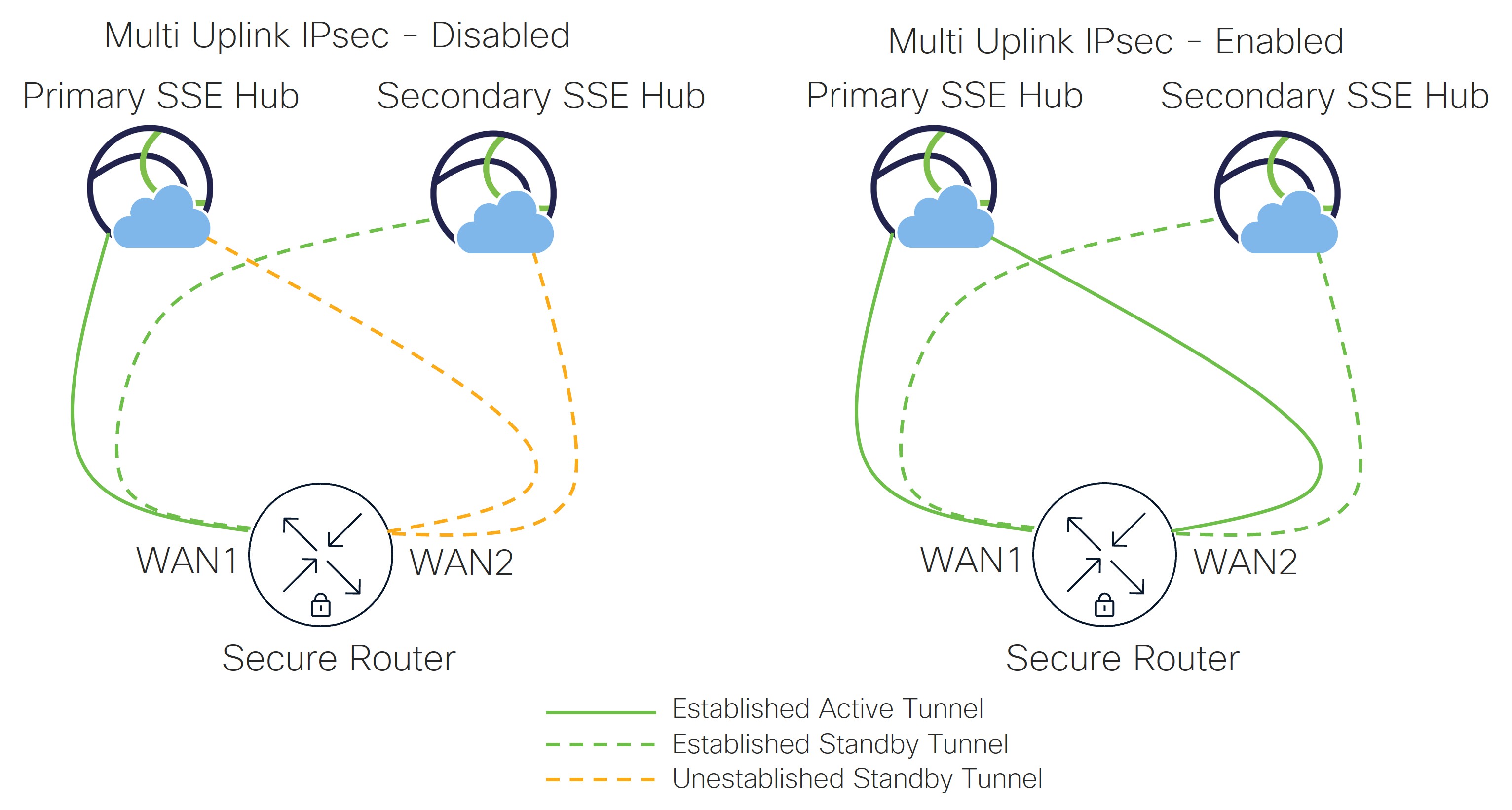
Adaptive Policy
Adaptive Policy is a feature that enables dynamic, intent-based security policies across a network by utilizing Security Group Tags (SGTs). It allows for granular control of network access by applying group-based policies that are independent of IP addresses or network topology, providing consistent security enforcement for both wired and wireless environments.
It simplifies security operations by enabling zero-trust segmentation, reducing attack surfaces, and accelerating deployment and maintenance of security policies across the network. It supports various group assignment techniques such as static VLAN to SGT mapping, VLAN to port mapping, RADIUS-based assignment, and Dashboard group policies. The policy enforcement occurs primarily at the egress point of the network devices, ensuring consistent application of security rules.
In the Unified Branch design, inter-VLAN segmentation via the Cisco secure router firewall is maintained, but micro-segmentation is introduced within VLAN 10 (DATA) through the use of SGTs. Four groups are defined in the example policy, two SGTs at the branch, and two SGTs for resources that may sit at the centralized data center.
For wireless (APs) access, the external RADIUS server will hand back a Group Policy name which contains the VLAN assignment and separately an SGT via RADIUS attribute. For wired (switches) access, Group Policy is not supported. The RADIUS server will hand back the VLAN assignment and an SGT directly via RADIUS attributes.
To retain and propagate SGTs, trunks on switches and secure routers that are connected to devices that can handle SGTs (APs, other secure routers, and other switches), are configured as Peer SGT capable. On the secure router, the Auto VPN fabric is also set to be Peer SGT capable if tags are to be propagated across the VPN.
Note: The C81xx series routers do not properly propagate SGT tags under certain software versions. This is fixed in MX version 26.1.4.
Cisco Extended Detection and Response (XDR)
Cisco XDR is a cloud-based solution designed to simplify security operations by integrating threat detection, investigation, and response across multiple security vectors including network, cloud, endpoint, email, identity, and applications. Cisco XDR provides unified visibility and deep context into advanced threats, helping security teams detect, prioritize, and respond to sophisticated threats faster and more effectively.
Cisco XDR integrates with Dashboard to provide comprehensive threat detection. When integrated, flow telemetry is sent from the XDR-enabled networks to XDR, and incidents can be viewed and managed from the Dashboard. For additional information, review the XDR documentation.
In this design, XDR is integrated into the Dashboard, and individual networks are XDR-enabled.
Network management services
Network management services that are included in the Unified Branch design are SNMP, Syslog, and NetFlow. Thousand Eyes and Splunk have also been included.
Simple Network Management Protocol (SNMP)
SNMP can be used for network configuration (SNMP queries) and/or for network monitoring (SNMP polling/queries or SNMP traps).
SNMP polling is supported, which can be used to query and gather information (read only access) either from the dashboard or directly from devices (routers, switches, and APs) within networks. SNMP traps are also supported by the dashboard. In this design, SNMP polling (dashboard and devices) and traps (dashboard) are enabled. The SNMP server is assumed to reside in the data center.
Dashboard polling
SNMP access to the dashboard is enabled at the Organization level.
In the settings, SNMP v3 access should be enabled and SNMP v2 should be disabled. SNMP v2 sends the community string in clear text and therefore is not recommended to be used over an unsecure network such as the internet. SNMP v3 is generally recommended since it includes provisions for privacy. When SNMP v3 is enabled, the Authentication mode, Authentication password, Privacy mode, and Privacy password fields will appear. For the additional settings:
Authentication mode should be set to SHA (MD5 is weaker), and privacy mode to AS128 (DES is weaker). The authentication and privacy passwords should be strong passwords consisting of letters, numbers, and special characters with a minimum of 8 characters in length. For the IP restrictions section, it is highly recommended to limit SNMP access to the dashboard to the minimal set of IP addresses needed. For example, if the organization NATs all traffic bound for the internet to the outside interface of a firewall, you may wish to restrict dashboard SNMP access to only that IP address. This will at least limit dashboard SNMP access to hosts within your organization so you can minimize the possibility of any data leakage out of your organization occurring through unauthorized access.
Note: For SNMP v3, the username is not a configurable parameter.
You can find the hostname:port and user settings along with an SNMPwalk example under the Privacy password field in SNMP settings. A timeout value of 10 seconds is recommended to give the SNMP agent enough time to respond. For more details, review the SNMP Overview and Configuration document.
Dashboard traps
SNMP traps allow for near real-time alerting of network events. SNMP traps are always forwarded from the cloud dashboard. SNMPv3 is used as best practice, so a username and passphrase are requested. SNMP traps use SHA1 for authentication and AES128 for privacy. The same passphrase is used for authentication and privacy. A public IP address must be used as the receiving server IP address since traps are generated from the dashboard. This may require port forwarding to be configured through the firewall as traffic needs to be initiated from the outside of the firewall.
To complete trap configuration, alerts should be chosen, and SNMP should be included as the default recipient under Organization > Setting > Alerts. This allows both email alerts and SNMP traps to be sent.
Device polling
Individual devices can also be polled using SNMP, which is done at the network level. Just as in previous sections, SNMP v1/v2 or v3 can be enabled, but v3 is recommended. For v3, pick a username and passphrase and specify the privacy mode (AES128 is recommended). SHA1 is used for authentication, and the passphrase is used for both authentication and privacy.
Typically, the SNMP server sits in the data center. By default, the secure router denies SNMP packets that come from outside (non-local, non-VPN) networks. To enable communication, go to Security & SD-WAN > Configure > Firewall > WAN appliance services and configure the allowed remote IP addresses next to the SNMP server.
Syslog
The devices can send event logs to a syslog server. The router can be configured to send Wireless events, Air Marshal events, switch events, appliance events, security events, URLs, and flows. If URLs are configured, any HTTP get request generates a syslog entry. If flows are selected, then inbound and outbound flows that are matched against a firewall rule will generate a syslog message. Individual firewall rules can be enabled to generate syslog messages if configured under Security & SD-WAN > Configure > Firewall.
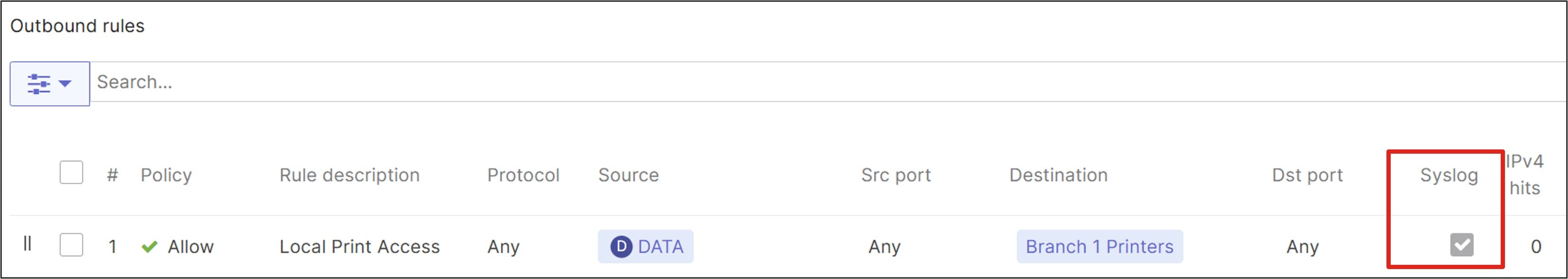
Syslog server configuration is under Network-wide settings. It allows you to configure a server address, port, and what event types to send messages to. This design leverages syslog.
NetFlow
NetFlow is a monitoring tool that exports IP network traffic flow statistics where it can be analyzed by a NetFlow collector. NetFlow is supported on secure routers, C9350s, C9300/X/L-Ms, and C9200/L-Ms. On the secure router, NetFlow data is only exported for traffic that hits the CPU (traffic that is routed or NAT’ed). NetFlow version 9 is supported. This design leverages NetFlow.
ThousandEyes
ThousandEyes is a digital experience monitoring platform that provides comprehensive, end-to-end visibility into the performance and availability of networks, applications, and services from any user to any application over any network. It enables enterprises to see, understand, and improve digital experiences by collecting multilayered telemetry data from vantage points distributed globally, including the internet, enterprise data centers, cloud, branch, and campus environments. This data helps quickly pinpoint the source of issues, accelerate resolution, and measure performance of critical services.
ThousandEyes integrates with Dashboard and employs Enterprise Agents on secure routers which serves to monitor data centers, cloud VPCs/VNETs, branch locations, and other internal or internet-connected network resources. When the Enterprise Agent is installed on the secure router, it connects to both the Dashboard and ThousandEyes cloud to securely download test and management settings.
The ThousandEyes test template includes ready-made settings like protocols, test timing, and alert options to make setting up monitoring applications easier. The Enterprise Agent runs as a service inside the secure router and uses the device’s hardware and software to perform the monitoring tasks.
Refer to the Meraki MX ThousandEyes Configuration Guide for more information.
Splunk
Splunk is a platform designed to collect, index, and analyze machine-generated data from various sources within an enterprise IT environment. It enables organizations to gain real-time operational intelligence by transforming raw, complex data into actionable insights. Splunk supports data ingestion from diverse formats and sources, including websites, applications, sensors, and devices, without requiring predefined schemas. It processes and stores data using indexes for efficient searching and analysis.
Splunk integration into the Dashboard brings device and network insights, top usage and performance rankings, configuration tracking, advanced assurance, SD-WAN and cellular gateway monitoring, licensing and firmware management, and more at the organizational level.
Splunk collects data through Cisco Meraki REST APIs as well as through Webhooks for near real-time alerts from the Meraki Dashboard. The Unified Branch design implements Splunk API integration, and optionally, Webhooks. Refer to Cisco Meraki Add-on for Splunk for more details.
Appendix A: References
● Unified Branch Solution Brief
● Cisco Network as Code Website
● Branch as Code Github Repository
● Unified Branch Small Branch Deployment Guide
● Unified Branch Medium Branch Deployment Guide
● Unified Branch Large Branch Deployment Guide