Features
A Cisco Threat Grid appliance provides safe and highly secure on-premises advanced malware analysis, with deep threat analytics and content. Threat Grid Appliances provide the complete Threat Grid malware analysis platform, installed on a single UCS server.
Many organizations that handle sensitive data, such as banks, health services, etc., must follow various regulatory rules and guidelines that will not allow certain types of files, such as malware artifacts, to be sent outside of the network for malware analysis. By maintaining a Cisco Threat Grid Appliance on-premises, organizations are able to send suspicious documents and files to it to be analyzed without leaving the network.
The Cisco Threat Grid M5 appliance supports Threat Grid Version 3.5.27 and later, and appliance version 2.7.2 and later.
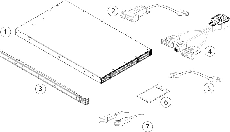
See Product ID Numbers for a list of the field-replaceable product IDs (PIDs) associated with the Threat Grid M5 appliance. You can remove and replace drives and power supplies. For all other internal component failures, you must send your chassis for return material authorization (RMA).
The following table lists the features of the Threat Grid M5.
|
Feature |
Description |
||||
|---|---|---|---|---|---|
|
Form factor |
1 RU |
||||
|
Rack mount |
Standard 19-inch (48.3 cm) 4-post EIA rack |
||||
|
Airflow |
Front to rear Cold aisle to hot aisle |
||||
|
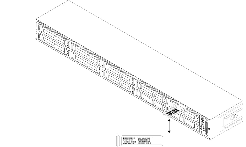
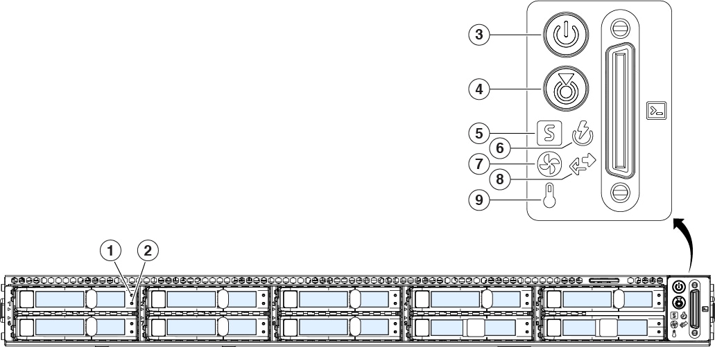
Pullout asset card |
Displays the serial number |
||||
|
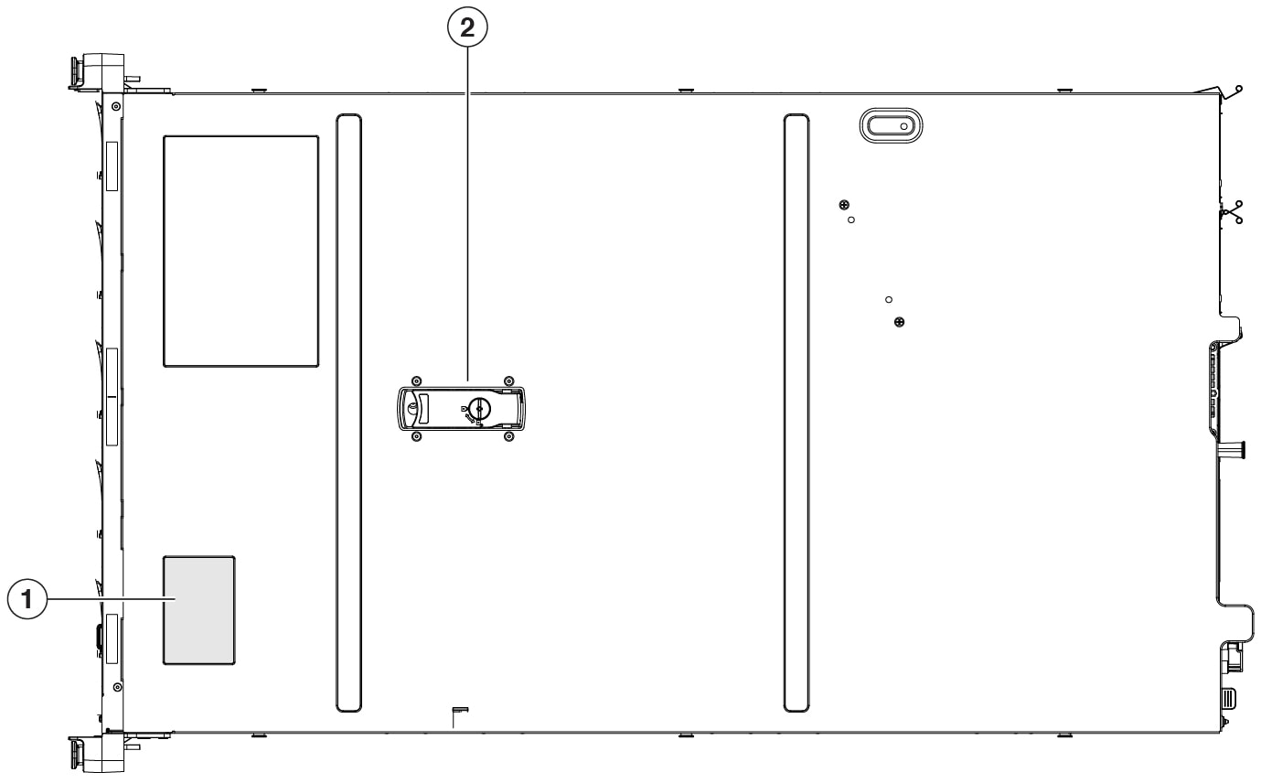
Grounding hole |
Two threaded holes for dual-hole grounding lug Use is optional; the supported AC power supplies have internal grounding, so no additional chassis grounding is required. |
||||
|
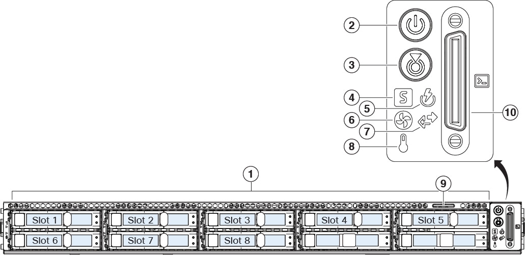
Unit identification button |
Yes |
||||
|
Power button |
On front panel |
||||
|
Processor |
Before January 2021: Two Intel Xeon 6140 After January 2021: Two Intel Xeon 6262 |
||||
|
Memory |
16 x 32 GB RAM Internal component only; not field-replaceable |
||||
|
RDIMMs |
Before January 2021: Two 16-GB DDR4-2400-MHz RDIMMs After January 2021: Two 16-GB DDR4-2933-MHz RDIMMs Internal component only; not field-replaceable |
||||
|
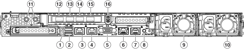
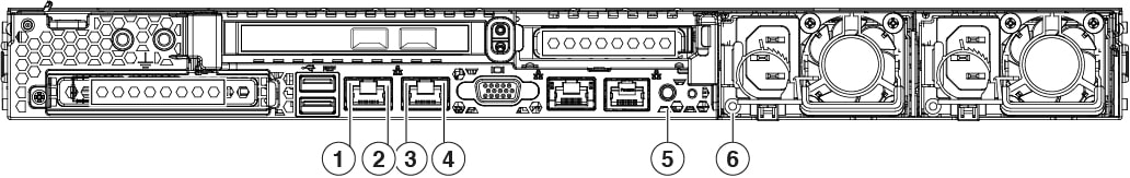
Management ports |
1 Gb built-in |
||||
|
Network ports |
Two 1-Gb 1000Base-T Two 10-Gb SFP+ |
||||
|
USB ports |
Two Version 3.0 Type A |
||||
|
VGA port |
One 3-row 15-pin DB-15 connector Enabled by default |
||||
|
SFP ports |
Four fixed SFP+ ports The two left SFP+ ports are not supported. |
||||
|
Supported SFP+ |
SFP-10G-LR (10 Gb) SFP-10G-SR (10 Gb)
|
||||
|
Serial console port |
RJ45 serial port running RS-232 (RS-232D TIA-561) |
||||
|
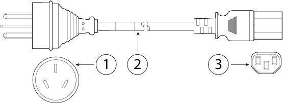
System power |
Two 770-W AC power supplies Hot-swappable and redundant as 1+1 |
||||
|
Power consumption |
2626 BTU/hr |
||||
|
Fans |
Six fans for front-to-rear cooling Internal component only; not field-replaceable |
||||
|
Storage |
Two 240-GB SATA SSDs in slots 1 and 2 Six 2.4-TB SAS HDDs in slots 3 though 8 RAID 1, hot-swappable |
||||


 Feedback