Introduction
The Admin UI is the recommended tool for administrators to use to configure the Threat Grid Appliance. It is a Web user interface that can be used once an IP address has been configured on the Admin interface.
The configuration includes the following steps:
-
Change Admin UI Admin Password
-
Review End User License Agreement
-
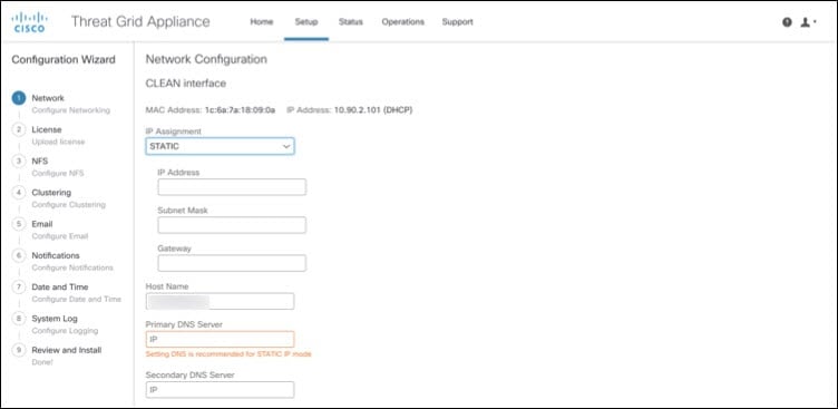
Configure Network Settings
-
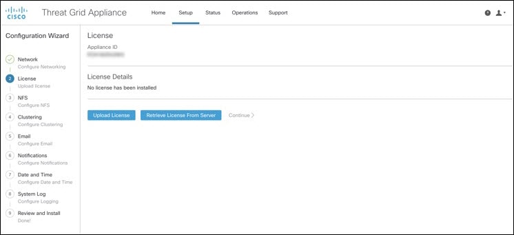
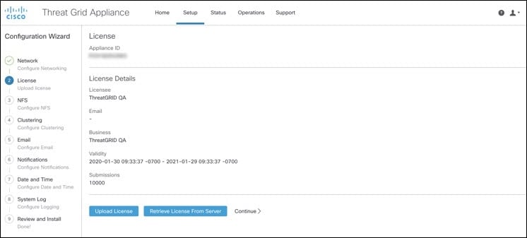
Install License
-
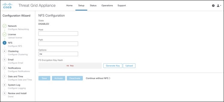
Configure NFS
-
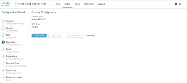
Configure Clustering
-
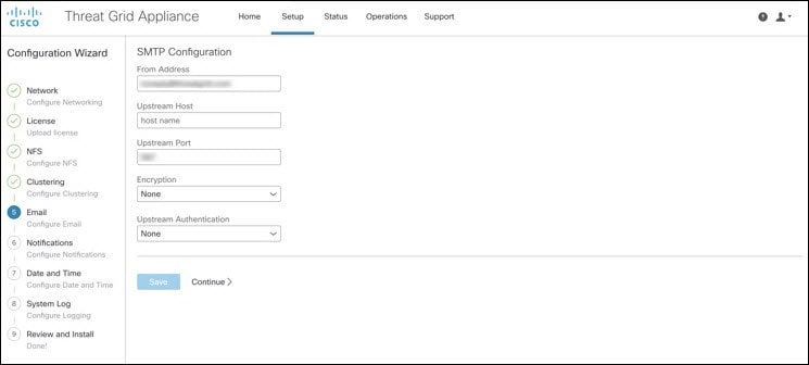
Configure Email
-
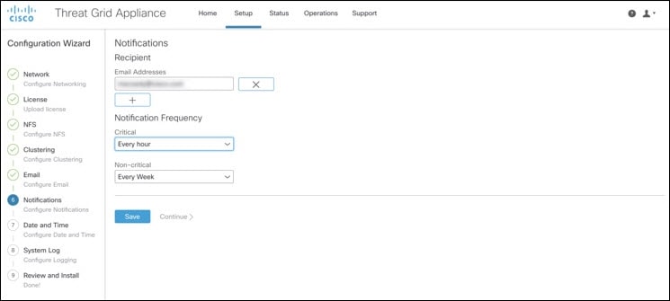
Configure Notifications
-
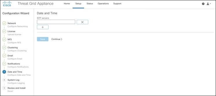
Configure Date and Time
-
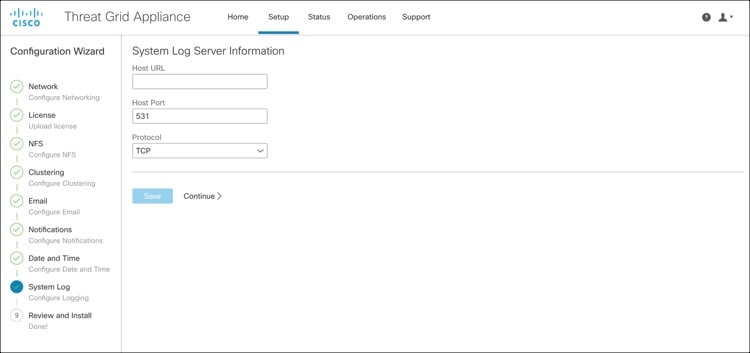
Configure System Log
-
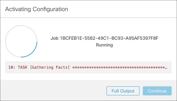
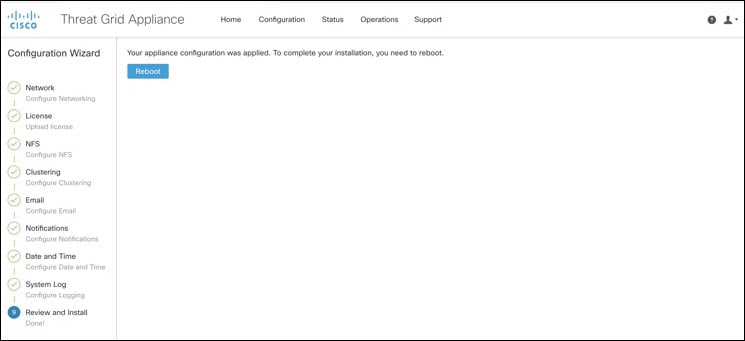
Review and Install Configuration Settings
 Note |
Not all configuration steps are completed using the configuration wizard. See the Cisco Threat Grid Appliance Administration Guide for configuring settings not included in the wizard, such as SSL Certificates and Backups. |
Important |
The steps in the following sections should be completed in one session to reduce the chance of an interruption to the IP address during configuration. |
Log In to the Admin UI
Perform the following steps to log in to the Threat Grid Admin UI.
Procedure
| Step 1 |
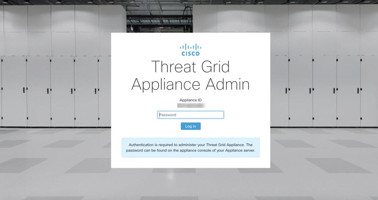
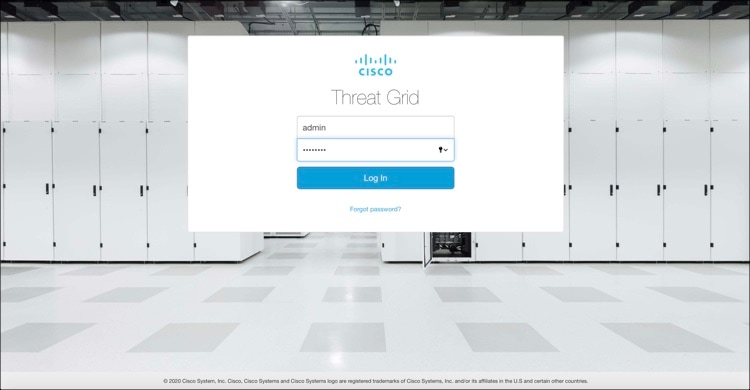
In a browser, enter the URL for the Admin UI (https://<adminIP>/ or https://<adminHostname>/) to open the Threat Grid Admin UI login screen.
|
||
| Step 2 |
Enter the initial Admin Password that you copied from the TGSH Dialog and click Log In. |
What to do next
Proceed to Change Admin Password.
Change Admin Password
The initial Admin password was generated randomly during the pre-ship Threat Grid installation and is visible as plain text in the TGSH Dialog. You must change the initial Admin password before continuing with the configuration.
Procedure
| Step 1 |
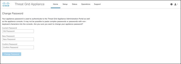
Enter the old password from the TGSH Dialog in the Current Password field. (You should have this password saved in a text file.) |
||
| Step 2 |
Enter a New Password and re-enter it in the Confirm New Password field. The new password must contain the following: 8 characters minimum, one number, one special character, at least one uppercase and one lowercase character. |
||
| Step 3 |
Click Change Password. The password is updated.
|
What to do next
Proceed to Review End User License Agreement.
Review End User License Agreement
Review the license agreement and confirm that you agree to it.
Procedure
| Step 1 |
Review the End User License Agreement. |
||
| Step 2 |
Scroll to the end and click I HAVE READ AND AGREE.
|
What to do next
Proceed to Configure Network Settings.
 Feedback