Cable and Register the Firewall

Cable the firewall and then register the firewall to the management center.

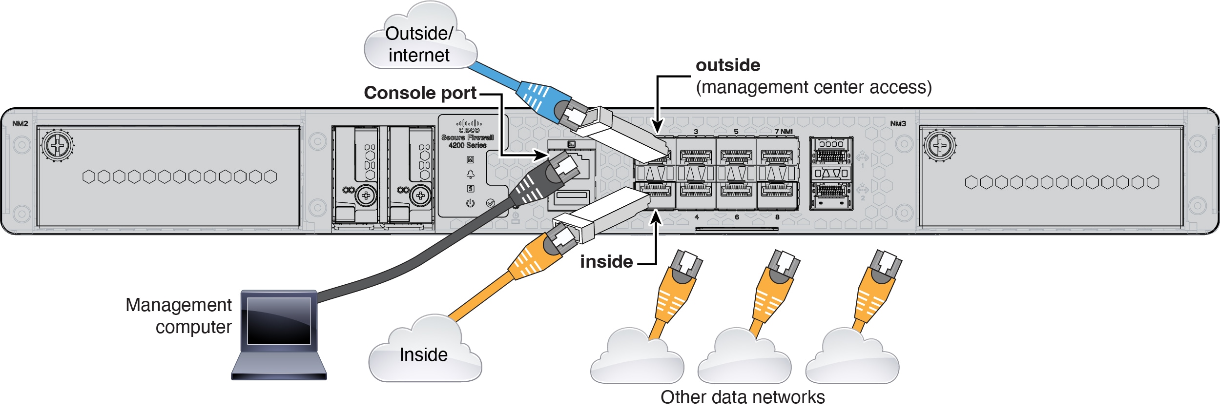
Cable the Firewall

  • Obtain a console cable—The firewall does not ship with a console cable by default, so you will need to buy a third-party USB-to-RJ-45 serial cable, for example.

  • Install SFPs into the data interface ports—The built-in ports are 1/10/25-Gb SFP28 ports that require SFP/SFP+/SFP28 modules.

  • See the hardware installation guide for more information.

Cabling for a Management Center at a Central Headquarters

Initial Configuration: CLI

Set the dedicated Management IP address, gateway, and other basic networking settings using the CLI setup script.

Procedure


Step 1

Connect to the console port and access the threat defense CLI. See Access the Threat Defense CLI.

Step 2

Complete the CLI setup script for the Management interface settings.

Note


You cannot repeat the CLI setup script unless you clear the configuration, for example, by reimaging. However, all of these settings can be changed later at the CLI using configure network commands. See Cisco Secure Firewall Threat Defense Command Reference.


You must accept the EULA to continue.
Press <ENTER> to display the EULA:                 
Cisco General Terms
[...]

Please enter 'YES' or press <ENTER> to AGREE to the EULA:

System initialization in progress.  Please stand by.
You must configure the network to continue.
Configure at least one of IPv4 or IPv6 unless managing via data interfaces.
Do you want to configure IPv4? (y/n) [y]:
Do you want to configure IPv6? (y/n) [y]: n

Guidance: Enter y for at least one of these types of addresses. Although you do not plan to use the Management interface, you must set an IP address, for example, a private address.

Configure IPv4 via DHCP or manually? (dhcp/manual) [manual]:

Guidance: Choose manual. DHCP is not supported when using the outside interface for manager access. Make sure this interface is on a different subnet from the manager access interface to prevent routing issues.

Enter an IPv4 address for the management interface [192.168.45.61]: 10.89.5.17
Enter an IPv4 netmask for the management interface [255.255.255.0]: 255.255.255.192
Enter the IPv4 default gateway for the management interface [data-interfaces]:

Guidance: Set the gateway to be data-interfaces. This setting forwards management traffic over the backplane so it can be routed through the outside interface.

Enter a fully qualified hostname for this system [firepower]: 1010-3
Enter a comma-separated list of DNS servers or 'none' [208.67.222.222,208.67.220.220,2620:119:35::35]:
Enter a comma-separated list of search domains or 'none' []: cisco.com
If your networking information has changed, you will need to reconnect.
Disabling IPv6 configuration: management0
Setting DNS servers: 208.67.222.222,208.67.220.220,2620:119:35::35
Setting DNS domains:cisco.com

Guidance: Set the Management interface DNS servers. These will probably match the outside interface DNS servers you set later, since they are both accessed from the outside interface.

Setting hostname as 1010-3
Setting static IPv4: 10.89.5.17 netmask: 255.255.255.192 gateway: data on management0
Updating routing tables, please wait...
All configurations applied to the system. Took 3 Seconds.
Saving a copy of running network configuration to local disk.
For HTTP Proxy configuration, run 'configure network http-proxy'

Guidance: Enter routed. Outside manager access is only supported in routed firewall mode.

Configuring firewall mode ...


Device is in OffBox mode - disabling/removing port 443 from iptables.
Update policy deployment information
    - add device configuration
    - add network discovery
    - add system policy

You can register the sensor to a Firepower Management Center and use the
Firepower Management Center to manage it. Note that registering the sensor
to a Firepower Management Center disables on-sensor Firepower Services
management capabilities.

When registering the sensor to a Firepower Management Center, a unique
alphanumeric registration key is always required.  In most cases, to register
a sensor to a Firepower Management Center, you must provide the hostname or
the IP address along with the registration key.
'configure manager add [hostname | ip address ] [registration key ]'

However, if the sensor and the Firepower Management Center are separated by a
NAT device, you must enter a unique NAT ID, along with the unique registration
key.
'configure manager add DONTRESOLVE [registration key ] [ NAT ID ]'

Later, using the web interface on the Firepower Management Center, you must
use the same registration key and, if necessary, the same NAT ID when you add
this sensor to the Firepower Management Center.
>
Step 3

Configure the outside interface for manager access.

configure network management-data-interface

You are then prompted to configure basic network settings for the outside interface.

Manual IP Address


> configure network management-data-interface
Data interface to use for management: ethernet1/1
Specify a name for the interface [outside]: internet
IP address (manual / dhcp) [dhcp]: manual
IPv4/IPv6 address: 10.10.6.7
Netmask/IPv6 Prefix: 255.255.255.0
Default Gateway: 10.10.6.1
Comma-separated list of DNS servers [none]: 208.67.222.222,208.67.220.220

Guidance: To retain the outside DNS servers after registration, you need to re-configure the DNS Platform Settings in the management center.


DDNS server update URL [none]:
Do you wish to clear all the device configuration before applying ? (y/n) [n]:

Configuration done with option to allow manager access from any network, if you wish to change the manager access network
use the 'client' option in the command 'configure network management-data-interface'.

Setting IPv4 network configuration.
Network settings changed.

>

IP Address from DHCP


> configure network management-data-interface
Data interface to use for management: ethernet1/1
Specify a name for the interface [outside]:
IP address (manual / dhcp) [dhcp]:  
DDNS server update URL [none]: https://dwinchester:pa$$w0rd17@domains.example.com/nic/update?hostname=<h>&myip=<a>
Do you wish to clear all the device configuration before applying ? (y/n) [n]:

Configuration done with option to allow manager access from any network, if you wish to change the manager access network 
use the 'client' option in the command 'configure network management-data-interface'.

Setting IPv4 network configuration.
Network settings changed.

> 

Step 4

Identify the management center.

configure manager add {hostname | IPv4_address | IPv6_address | DONTRESOLVE} reg_key nat_id

  • {hostname | IPv4_address | IPv6_address | DONTRESOLVE}—Specifies either the FQDN or IP address of the management center. If the management center is not directly addressable, use DONTRESOLVE, in which case the firewall must have a reachable IP address or hostname.

  • reg_key—Specifies a one-time registration key of your choice that you will also specify on the management center when you register the threat defense. The registration key must be between 2 and 36 characters. Valid characters include alphanumerical characters (A–Z, a–z, 0–9) and the hyphen (-).

  • nat_id—Specifies a unique, one-time string of your choice that you will also specify on the management center. The NAT ID must be between 2 and 36 characters. Valid characters include alphanumerical characters (A–Z, a–z, 0–9) and the hyphen (-). This ID cannot be used for any other devices registering to the management center.

Example:


> configure manager add fmc-1.example.com regk3y78 natid56
Manager successfully configured.

Step 5

Shut down the threat defense so you can send the device to the remote branch office.

It's important that you shut down your system properly. Simply unplugging the power or pressing the power switch can cause serious file system damage. Remember that there are many processes running in the background all the time, and unplugging or shutting off the power does not allow the graceful shutdown of your system.

  1. Enter the shutdown command.

  2. Observe the Power LED and Status LED to verify that the chassis is powered off (appear unlit).

  3. After the chassis has successfully powered off, you can then unplug the power to physically remove power from the chassis if necessary.


Register the Firewall with the Management Center

Register the firewall to the management center.

Procedure


Step 1

Log into the management center.

  1. Enter the following URL.

    https://fmc_ip_address

  2. Enter your username and password.

  3. Click Log In.

Step 2

Choose Devices > Device Management.

Step 3

From the Add drop-down menu, choose Device (Wizard).

Step 4

Click Registration Key, and then click Next.

Figure 1. Device Registration Method
Device Registration Method

Step 5

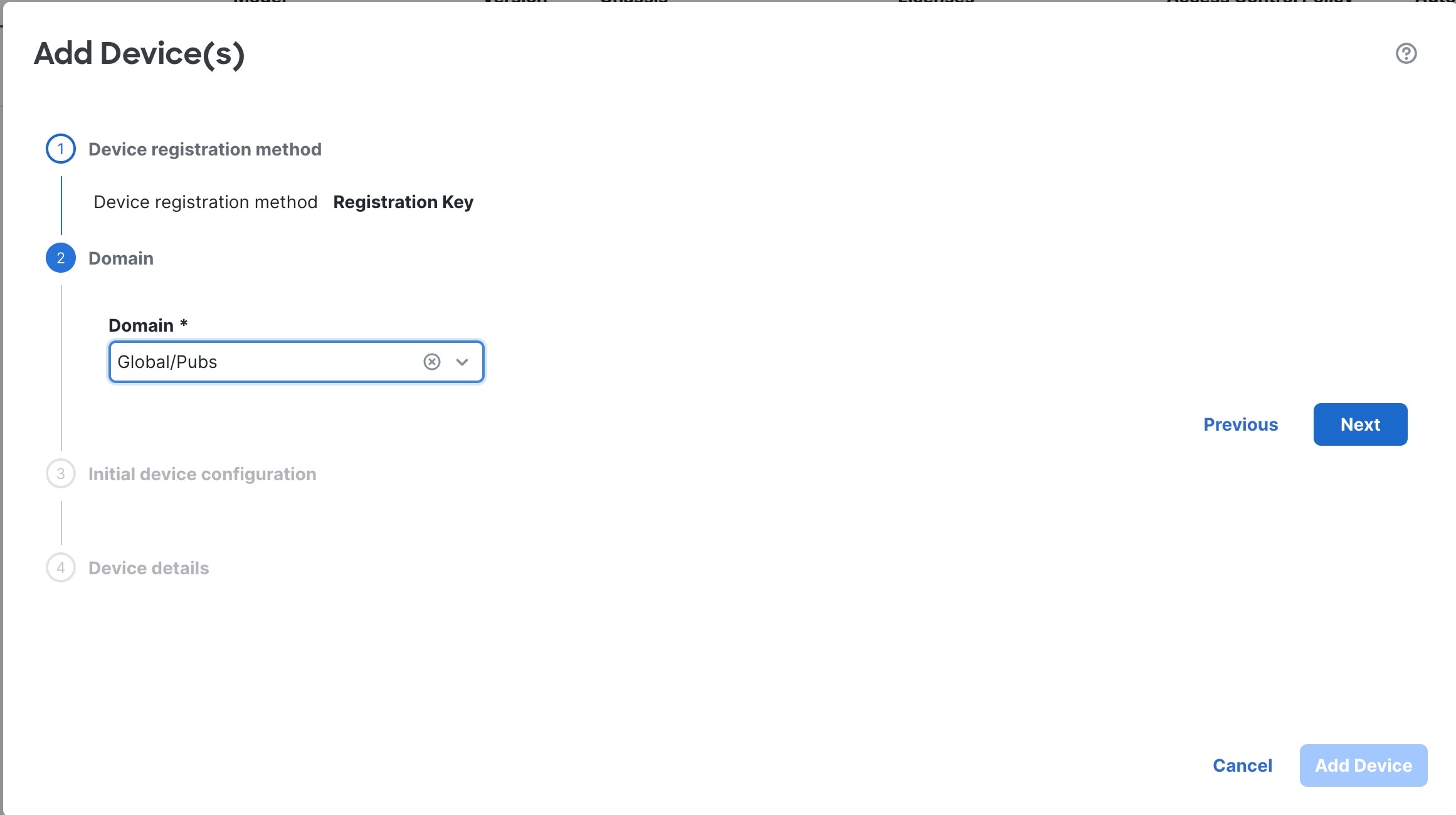
In a multi-domain environment, choose the Domain from the drop-down list and click Next.

Figure 2. Domain
Domain

Step 6

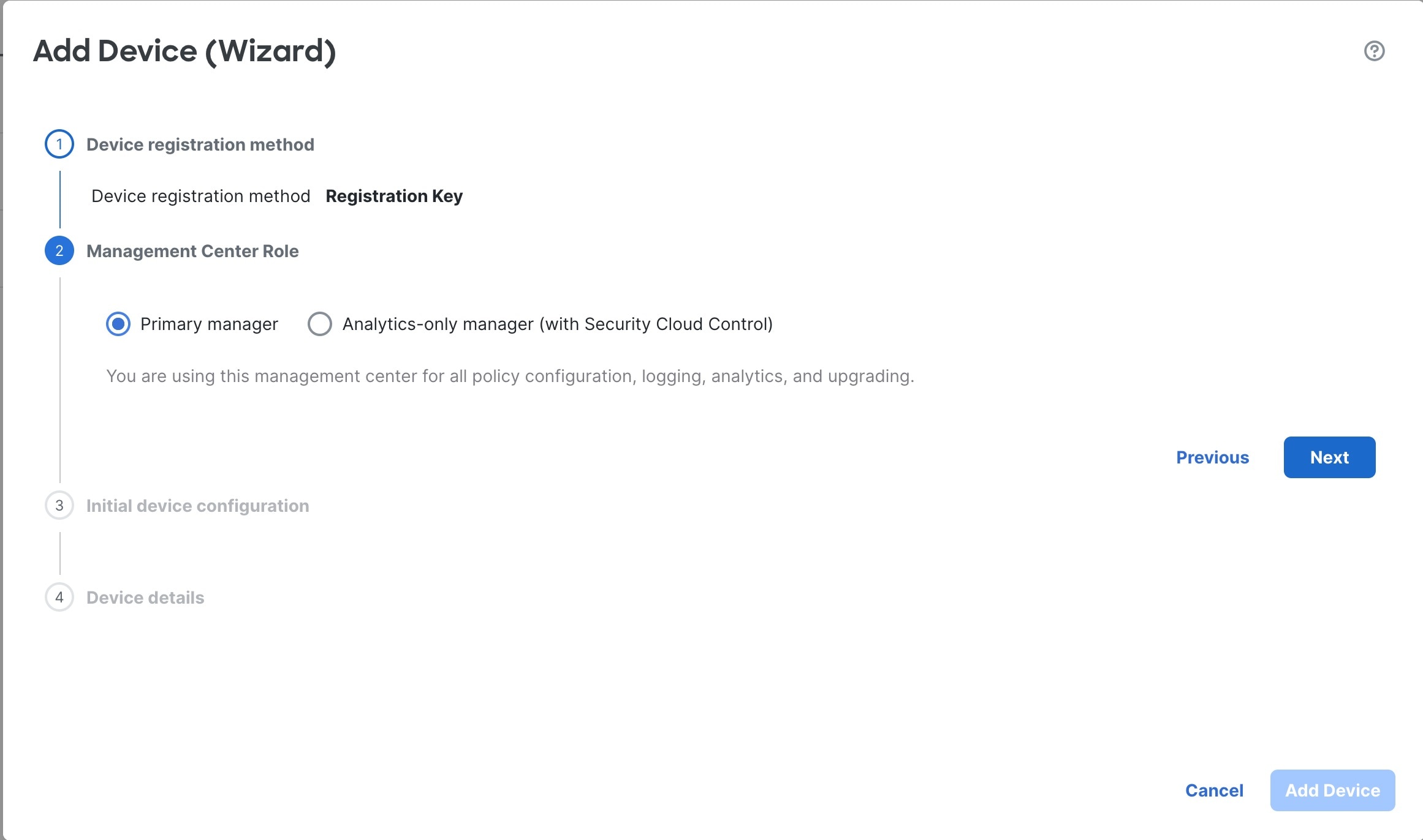
Click Primary manager.

Figure 3. Management Center Role
Management Center Role

Step 7

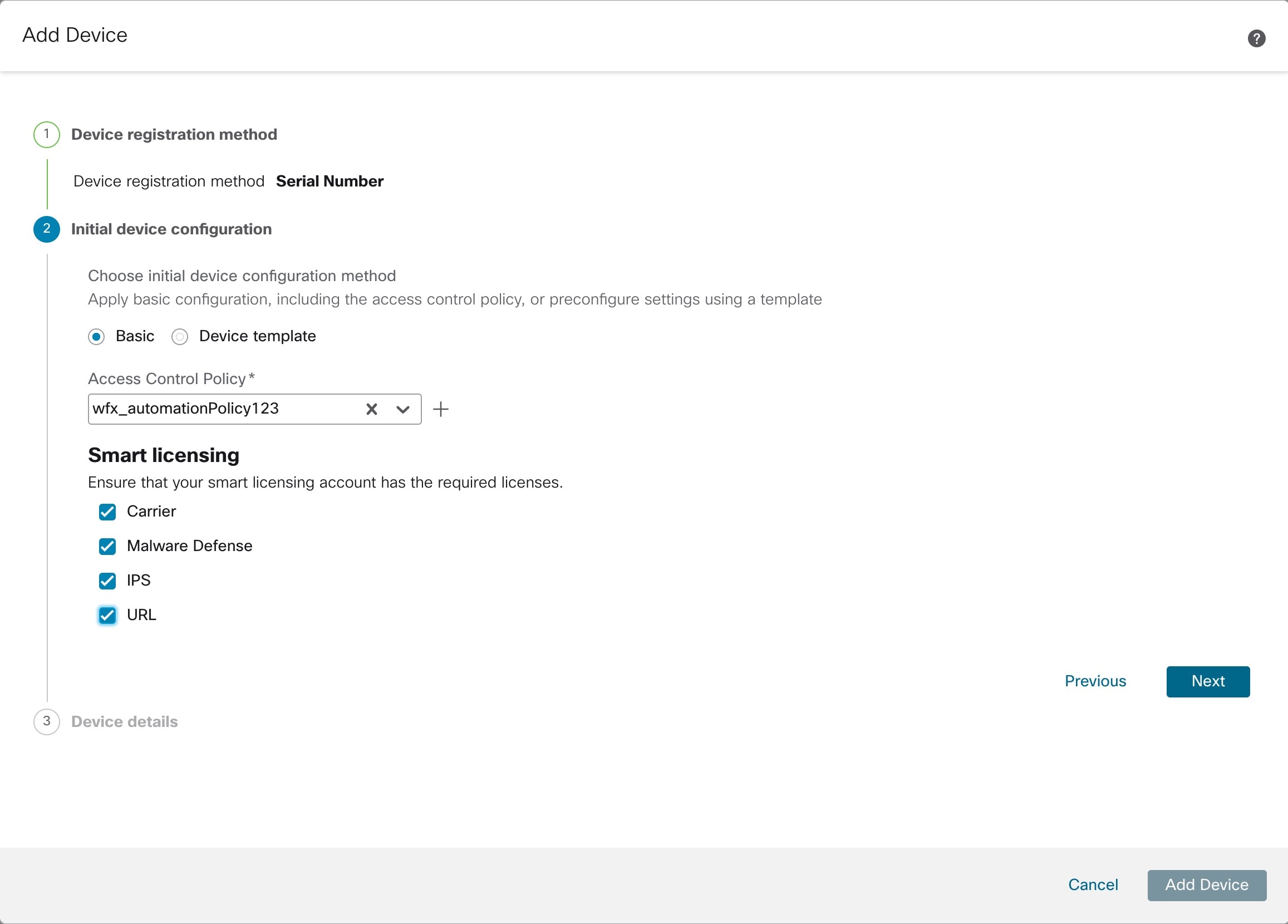
For the Initial Device Configuration, click Basic.

Figure 4. Initial Device Configuration
Initial Device Configuration
  1. Choose an initial Access Control Policy to deploy to the device at registration, or create a new policy. Unless you already have a customized policy you know you need to use, choose Create new policy, and choose Block all traffic. You can change this later to allow traffic; see Configure an Access Control Rule.

  2. Choose Smart Licensing licenses to apply to the device.

    You can also apply licenses after you add the device, from the System > Licenses > Smart Licenses page, including the Secure Client remote access VPN license.

  3. Click Next.

Step 8

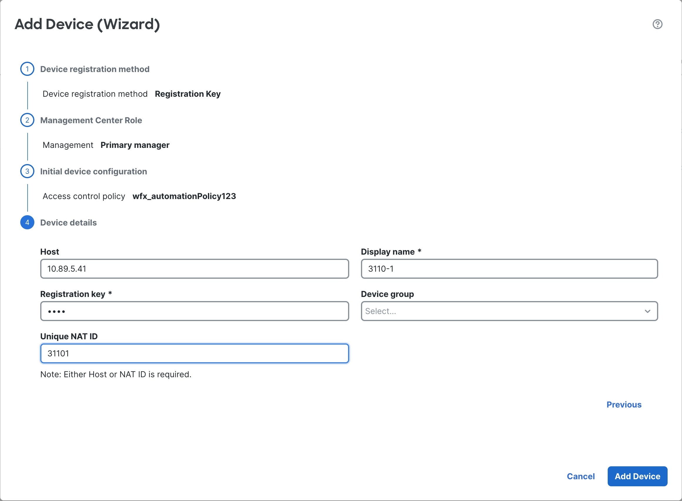
Specify the Device details.

Figure 5. Device Details
Device Details
  1. For the Host, enter the IP address or the hostname of the device you want to add. Leave this field blank if you don't know the device IP address (for example, it's behind NAT).

  2. For the Display name, enter a name for the device as you want it to display in the management center. You cannot change this name later.

  3. For the Registration Key, enter the same registration key from your initial configuration.

  4. (Optional) Add the device to a Device group

  5. For the Unique NAT ID, enter the same ID from your initial configuration.

  6. Check Transfer Packets so that for each intrusion event, the device transfers the packet to the management center for inspection.

    For each intrusion event, the device sends event information and the packet that triggered the event to the management center for inspection. If you disable it, only event information will be sent to the management center; the packet will not be sent.

Step 9

Click Add Device.

It may take up to two minutes for the management center to verify the device’s heartbeat and establish communication. If the registration succeeds, the device is added to the list. If it fails, you will see an error message. If the device fails to register, check the following items:

  • Ping—Access the device CLI, and ping the management center IP address using the following command:

    ping system ip_address

    If the ping is not successful, check your network settings using the show network command. If you need to change the device IP address, use the configure network {ipv4 | ipv6} manual command.

  • Registration key, NAT ID, and management center IP address—Make sure you are using the same registration key, and if used, NAT ID, on both devices. You can set the registration key and NAT ID on the device using the configure manager add command.

For more troubleshooting information, see https://cisco.com/go/fmc-reg-error.