Install the Cisco SNS 3515 and Cisco SNS 3595 Hardware Appliances
This section describes how to install your Cisco SNS 3515 or 3595 appliance and connect it to the network. It contains:
- Install the Cisco SNS 3515 or 3595 Appliance in a Rack
- Cisco Integrated Management Controller
- Connect Cables
- Connect and Power On the Cisco SNS 3515 or 3595 Appliance
Before you begin the installation, read the Regulatory Compliance and Safety Information for the Cisco SNS 3515 or Cisco SNS 3595 Hardware Appliance.
 Warning |
Warning: Only trained and qualified personnel should be allowed to install, replace, or service this equipment. Statement 1030 |
Warning |
Warning: This unit is intended for installation in restricted access areas. A restricted access area can be accessed only through the use of a special tool, lock and key, or other means of security. Statement 1017 |
Install the Cisco SNS 3515 or 3595 Appliance in a Rack
This section describes how to install the Cisco SNS 3515 or Cisco SNS 3595 appliance in a rack.
Install the Side Rails
Warning |
Warning: To prevent bodily injury when mounting or servicing this unit in a rack, you must take special precautions to ensure that the system remains stable. The following guidelines are provided to ensure your safety: This unit should be mounted at the bottom of the rack if it is the only unit in the rack. When mounting this unit in a partially filled rack, load the rack from the bottom to the top with the heaviest component at the bottom of the rack. If the rack is provided with stabilizing devices, install the stabilizers before mounting or servicing the unit in the rack. Statement 1006 |
Procedure
|
Step 1 |
Attach the inner rails to the sides of the server: 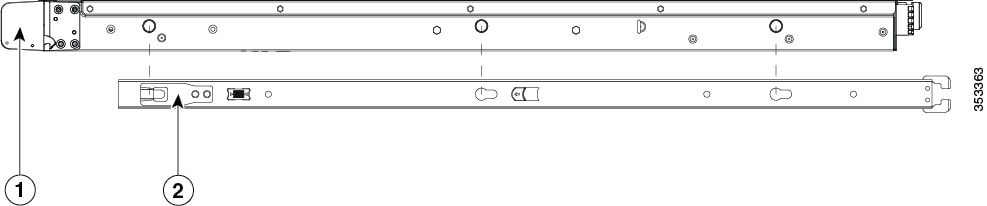
|
||||||||||
|
Step 2 |
Open the front securing plate on both slide-rail assemblies. The front end of the slide-rail assembly has a spring-loaded securing plate that must be open before you can insert the mounting pegs into the rack-post holes. On the outside of the assembly, push the green arrow button toward the rear to open the securing plate. 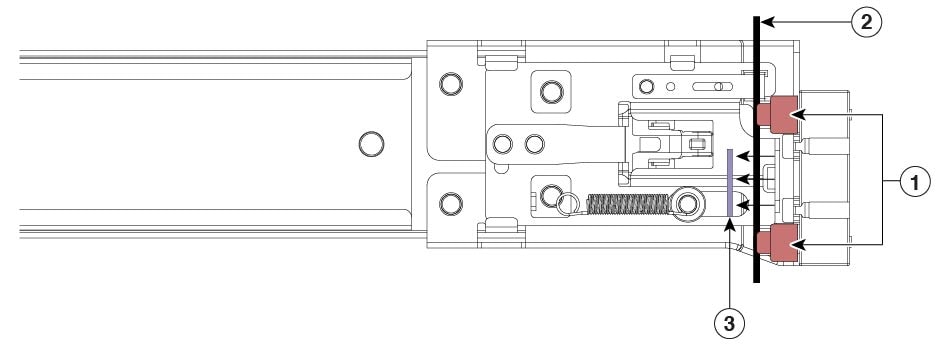
|
||||||||||
|
Step 3 |
Install the outer slide rails into the rack: |
||||||||||
|
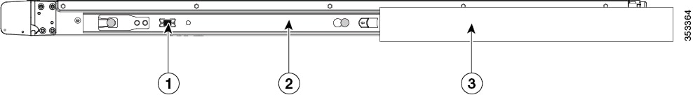
Step 4 |
Insert the server into the slide rails:
|
||||||||||
|
Step 5 |
(Optional) Secure the server in the rack more permanently by using the two screws that are provided with the slide rails. Perform this step if you plan to move the rack with servers installed. With the server fully pushed into the slide rails, open a hinged slam latch lever on the front of the server and insert the screw through the hole that is under the lever. The screw threads into the static part of the rail on the rack post and prevents the server from being pulled out. Repeat for the opposite slam latch. |
||||||||||
What to do next
Install the Cable Management Arm (Optional)
 Note |
The CMA is reversible left to right. To reverse the CMA, see Reversing the Cable Management Arm (Optional) before installation. |
Procedure
|
Step 1 |
With the server pushed fully into the rack, slide the CMA tab of the CMA arm that is farthest from the server onto the end of the stationary slide rail that is attached to the rack post (see the following figure). Slide the tab over the end of the rail until it clicks and locks. |
||||||||
|
Step 2 |
Slide the CMA tab that is closest to the server over the end of the inner rail that is attached to the server (see the following figure). Slide the tab over the end of the rail until it clicks and locks. |
||||||||
|
Step 3 |
Pull out the width-adjustment slider that is at the opposite end of the CMA assembly until it matches the width of your rack (see the following figure). |
||||||||
|
Step 4 |
Slide the CMA tab that is at the end of the width-adjustment slider onto the end of the stationary slide rail that is attached to the rack post (see the following figure). Slide the tab over the end of the rail until it clicks and locks. |
||||||||
|
Step 5 |
Open the hinged flap at the top of each plastic cable guide and route your cables through the cable guides as desired. 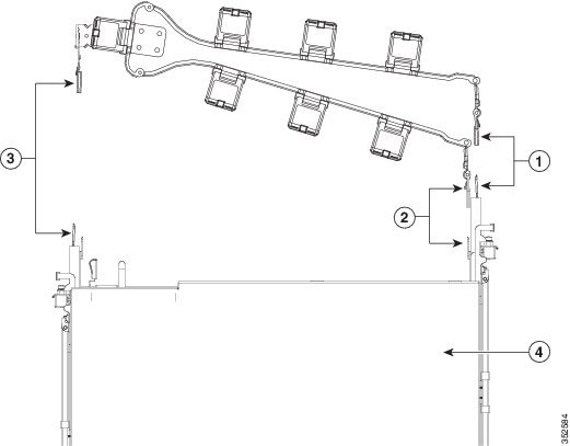
|
Reverse the Cable Management Arm (Optional)
Procedure
|
Step 1 |
Rotate the entire CMA assembly 180 degrees. The plastic cable guides must remain pointing upward. |
||||
|
Step 2 |
Flip the tabs at the end of each CMA arm so that they point toward the rear of the server. |
||||
|
Step 3 |
Pivot the tab that is at the end of the width-adjustment slider. Depress and hold the metal button on the outside of the tab and pivot the tab 180 degrees so that it points toward the rear of the 
|
Connect Cables
Attach cables (such as keyboard, monitor cables, if required) to the rear of the server. Route the cables properly and use the cable straps to secure the cables to the slide rails. See the Cisco SNS 3515 or SNS 3595 Appliance Back Panel View for reference on the rear view of the appliance.
Connect the Network Interface
Warning |
Warning: Do not work on the system or connect or disconnect cables during periods of lightning activity. Statement 1001 |
This section describes how to connect the Cisco SNS-3515 or Cisco SNS-3595 appliance Ethernet port.
The Ethernet connector supports Serial over LAN (SOL) cables. The RJ-45 port supports standard straight-through and crossover Category 5 unshielded twisted-pair (UTP) cables. Cisco does not supply Category 5 UTP cables; these cables are available commercially.
To connect the cable to the appliance Ethernet port:
Procedure
|
Step 1 |
Verify that the appliance is turned off. |
|
Step 2 |
Connect one end of the cable to the GigabitEthernet 0 port on the appliance. |
|
Step 3 |
Connect the other end to a switch in your network. |
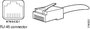
Ethernet Port Connector
Ethernet Port Pin-out
The Cisco SNS 3515 or Cisco SNS-3595 appliance comes with six integrated dual-port Ethernet controllers. The controllers provide an interface for connecting to 10-Mb/s, 100-Mb/s, or 1000-Mb/s networks and provide full-duplex (FDX) capability, which enables simultaneous transmission and reception of data on the Ethernet LAN. Cisco ISE supports multiple NICs.
To access the Ethernet port, connect a Category 3, 4, 5, 5E, or 6 unshielded twisted-pair (UTP) cable to the RJ-45 connector on the back of the appliance.
The following table describes the UTP cable categories.
| Type | Description |
|---|---|
|
10BASE-T |
EIA Categories 3, 4, or 5 UTP (2 or 4 pair) up to 328 ft (100 m) |
|
100BASE-TX |
EIA Category 5 UTP (2 pair) up to 328 ft (100 m) |
|
1000BASE-T |
EIA Category 6 UTP (recommended), Category 5E UTP or 5 UTP (2 pair) up to 328 ft (100 m) |
The following figure shows the RJ-45 port and plug.
|
Ethernet Port Pin |
Signal |
Description |
|---|---|---|
|
1 |
TxD+ |
Transmit data + |
|
2 |
TxD- |
Transmit data - |
|
3 |
RxD+ |
Receive data + |
|
4 |
Termination network |
No connection |
|
5 |
Termination network |
No connection |
|
6 |
RxD- |
Receive data- |
|
7 |
Termination network |
No connection |
|
8 |
Termination network |
No connection |
Connect the Console
Warning |
Warning: Do not work on the system or connect or disconnect cables during periods of lightning activity. Statement 1001 |
Your Cisco SNS-3515 or Cisco SNS-3595 appliance has a DCE-mode console port for connecting a console terminal to your appliance. The appliance uses a DB-9 serial connector for the console port.
The console port on the Cisco SNS-3515 or Cisco SNS-3595 appliance includes an EIA/TIA-232 asynchronous serial (DB-9) connector. This serial console connector (port) allows you to access the appliance locally by connecting a terminal—either a PC running terminal-emulation software or an ASCII terminal—to the console port.
To connect a PC running terminal-emulation software to the console port, use a DB-9 female to DB-9 female straight-through cable.
To connect an ASCII terminal to the console port, use a DB-9 female to DB-25 male straight-through cable with a DB-25 female to DB-25 female gender changer.
To connect a terminal or a PC running terminal-emulation software to the console port on the Cisco SNS-3515 or Cisco SNS-3595 appliance:
Procedure
|
Step 1 |
Connect the terminal using a straight-through cable to the console port. |
|
Step 2 |
Configure your terminal or terminal-emulation software for 9600 baud, 8 data bits, no parity, 1 stop bit, and no hardware flow control. |
Connect the Keyboard and Video Monitor
Warning |
Do not work on the system or connect or disconnect cables during periods of lightning activity. Statement 1001 |
This section describes how to connect a keyboard and video monitor to the Cisco SNS-3515 or Cisco SNS-3595 appliance.
You can connect the keyboard and video monitor to the Cisco SNS-3515 or Cisco SNS-3595 appliance using the KVM connector available in the front panel of the Cisco SNS-3515 or Cisco SNS-3595 appliance. A KVM cable is shipped along with the appliance that provides two USB, one VGA, and one serial connector.
The Cisco SNS-3515 or Cisco SNS-3595 appliance does not provide support for a mouse.
The Cisco SNS-3515 or Cisco SNS-3595 provides USB ports on the rear of the appliance that can be used to connect a keyboard and video monitor.
To connect a keyboard and video monitor to the appliance:
Procedure
|
Step 1 |
Verify that the appliance is turned off. |
|
Step 2 |
Connect the end of the keyboard cable to the PS/2 (keyboard) port which is located on the back panel of the appliance. |
|
Step 3 |
Connect the end of the video monitor cable to the PS/2 (video monitor) port which is located on the back panel of the appliance. |
|
Step 4 |
Power on the appliance. |
Cable Management
Cable management is the most visual aspect of your appliance setup. However, cable management is often overlooked because it can be time consuming.
Equipment racks and enclosures house more equipment today than ever before. This growth has increased the need for organized cable management both inside and outside the rack. Poor cable management not only leads to damaged cables or increased time for adding or changing cables, but also blocks critical airflow or access. These problems can lead to inefficiencies in the performance of your equipment or even downtime.
There are many solutions to address cable management. They can range from simple cable management rings, to vertical or horizontal organizers, to troughs and ladders.
All Cisco SNS-3515 or Cisco SNS-3595 appliance cables should be properly dressed so as not to interfere with each other or other pieces of equipment. Use local practices to ensure that the cables attached to your appliance are properly dressed.
Proceed to the next section, Connect and Power On the Cisco SNS 3515 or 3595 Appliance, to continue the installation process.
Connect and Power On the Cisco SNS 3515 or 3595 Appliance
Connect and Power On the Server (Standalone Mode)
Note |
This section describes how to power on the server, assign an IP address, and connect to server management when using the server in standalone mode. |
The server is shipped with the following default settings:
-
The NIC mode is Shared LOM EXT.
Shared LOM EXT mode enables the 1-Gb Ethernet ports and the ports on any installed Cisco virtual interface card (VIC) to access Cisco Integrated Management Interface (Cisco IMC). If you want to use the 10/100/1000 dedicated management ports to access Cisco IMC, you can connect to the server and change the NIC mode as described in Step 1 of the procedures given below.
-
The NIC redundancy is active-active.
All Ethernet ports are utilized simultaneously.
-
DHCP is enabled.
-
IPv4 is enabled.
You can connect to the system using two methods:
-
Local setup—Use this procedure if you want to connect a keyboard and monitor to the system for setup. This procedure can use a KVM cable (Cisco PID N20-BKVM) or the ports on the rear of the server. See Local Connection Procedure.
-
Remote setup—Use this procedure if you want to perform setup through your dedicated management LAN. See Remote Connection Procedure.
Note |
To configure the system remotely, you must have a DHCP server on the same network as the system. Your DHCP server must be preconfigured with the range of MAC addresses for this server node. The MAC address is printed on a label on the rear of the server node. This server node has a range of six MAC addresses assigned to the Cisco IMC. The MAC address printed on the label is the beginning of the range of six contiguous MAC addresses. |
Local Connection Procedure
Procedure
|
Step 1 |
Attach a power cord to each power supply unit in your server, and then attach each power cord to a grounded AC power outlet. See Power Specifications for power specifications. Wait for approximately two minutes to let the server boot in standby power during the first bootup. You can verify system power status by looking at the system Power Status LED on the front panel (see LED Indicators on Cisco SNS 3515 and 3595 Appliances). The system is in standby power mode when the LED is amber. |
|
Step 2 |
Connect a USB keyboard and VGA monitor to the server using one of the following methods:
|
|
Step 3 |
Open the Cisco IMC Configuration Utility: |
Remote Connection Procedure
Procedure
|
Step 1 |
Attach a power cord to each power supply unit in your server, and then attach each power cord to a grounded AC power outlet. See Power Specifications for power specifications. Wait for approximately two minutes to let the server boot in standby power during the first bootup. You can verify system power status by looking at the system Power Status LED on the front panel (see LED Indicators on Cisco SNS 3515 and 3595 Appliances). The system is in standby power mode when the LED is amber. |
||
|
Step 2 |
Plug your management Ethernet cable into the dedicated management port on the rear panel (see Cisco SNS 3515 or SNS 3595 Appliance Back Panel View). |
||
|
Step 3 |
Allow your preconfigured DHCP server to assign an IP address to the server node. |
||
|
Step 4 |
Use the assigned IP address to access and log in to the Cisco IMC for the server node. Consult with your DHCP server administrator to determine the IP address.
|
||
|
Step 5 |
From the Cisco IMC Server Summary page, click Launch KVM Console. A separate KVM console window opens. |
||
|
Step 6 |
From the Cisco IMC Summary page, click Power Cycle Server. The system reboots. |
||
|
Step 7 |
Select the KVM console window.
|
||
|
Step 8 |
When prompted, press F8 to enter the Cisco IMC Configuration Utility. This utility opens in the KVM console window. This utility has two windows that you can switch between by pressing F1 or F2. |
||
|
Step 9 |
Continue with Setup CIMC Configuration Utility. |
 Feedback