Segmentation
Policy Sets
Cisco ISE is a policy-based, network-access-control solution, which offers network access policy sets, allowing you to manage several different network access use cases such as wireless, wired, guest, and client provisioning. Policy sets (both network access and device administration sets) enable you to logically group authentication and authorization policies within the same set. You can have several policy sets based on an area, such as policy sets based on location, access type and similar parameters. When you install ISE, there is always one policy set defined, which is the default policy set, and the default policy set contains within it, predefined and default authentication, authorization and exception policy rules.
When creating policy sets, you can configure these rules (configured with conditions and results) in order to choose the network access services on the policy set level, the identity sources on the authentication policy level, and network permissions on the authorization policy levels. You can define one or more conditions using any of the attributes from the Cisco ISE-supported dictionaries for a variety of different vendors. Cisco ISE allows you to create conditions as individual policy elements that can be reused.
The network access service to be used per policy set to communicate with the network devices is defined at the top level of that policy set. Network access services include:
-
Allowed protocols—the protocols configured to handle the initial request and protocol negotiation
-
A proxy service—sends requests to an external RADIUS server for processing
 Note |
From the Device Administration work center, you can also select a relevant TACACS server sequence for your policy set. Use the TACACS server sequence to configure a sequence of TACACS proxy servers for processing. |
Policy sets are configured hierarchically, where the rule on the top level of the policy set, which can be viewed from the Policy Set table, applies to the entire set and is matched before the rules for the rest of the policies and exceptions. Thereafter, rules of the set are applied in this order:
-
Authentication policy rules
-
Local policy exceptions
-
Global policy exceptions
-
Authorization policy rules
Note |
Policy Sets functionality is identical for network access and for device administration policies. All processes described in this chapter can be applied when working with both the Network Access and the Device Administration work centers. This chapter specifically discusses the Network Access work center policy sets. To access this work center, choose . |
Policy Set Configuration Settings
The following table describes the fields in the Policy Sets page, from which you can configure policy sets, including authentication, exception and authorization policies. For network access policies, choose . For device administration policies, choose .
|
Fields |
Usage Guidelines |
|---|---|
|
Status |
Choose the status of this policy. It can be one of the following:
|
|
Policy Set Name |
Enter a unique name for this policy set. |
|
Conditions |
From a new policy row, click the plus (+) icon or from an existing policy row, click the Edit icon to open the Conditions Studio. |
|
Description |
Enter a unique description for the policy. |
|
Allowed Protocols / Server Sequence |
Choose an allowed protocol that you have already created, or click the (+) sign to Create a New Allowed Protocol , to Create a New Radius Sequence, or to Create a TACACS Sequence. |
|
Conditions |
From a new exceptions row, click the plus (+) icon or from an existing exception row, click the Edit icon to open the Conditions Studio. |
|
Hits |
Hits are a diagnostic tool indicating the number of times the conditions have matched. Hover over the icon to view when this was last updated, reset to zero and to view the frequency of updates. |
|
Actions |
Click the cog icon
|
|
View |
Click the arrow icon to open the Set view of the specific policy set and view its authentication, exception and authorization sub-policies. |
 from the Actions column to view and select different actions:
Authentication Policies
Each policy set can contain multiple authentication rules that together represent the authentication policy for that set. Priority of the authentication policies is determined based on the order to those policies as they appear within the policy set itself (from the Set view page in the Authentication Policy area).
Cisco ISE dynamically chooses the network access service (either an allowed protocol a server sequence) based on the settings configured on the policy set level, and thereafter checks the identity sources and results from the authentication and authorization policy levels. You can define one or more conditions using any of the attributes from the Cisco ISE dictionary. Cisco ISE allows you to create conditions as individual policy elements that can be stored in the Library and then can be reused for other rule-based policies.
The identity method, which is the result of the authentication policy, can be any one of the following:
-
Deny access—Access to the user is denied and no authentication is performed.
-
Identity database—A single identity database that can be any one of the following:
-
Internal users
-
Guest users
-
Internal endpoints
-
Active Directory
-
Lightweight Directory Access Protocol (LDAP) database
-
RADIUS token server (RSA or SafeWord server)
-
Certificate authentication profile
-
-
Identity source sequences—A sequence of identity databases that is used for authentication.
The default policy set implemented at initial Cisco ISE installation includes the default ISE authentication and authorization rules. The default policy set also includes additional flexible built-in rules (that are not defaults) for authentication and authorization. You can add additional rules to those policies and you can delete and change the built-in rules but you cannot remove the default rules and you cannot remove the default policy set.
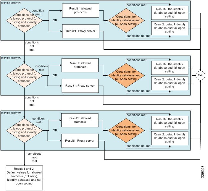
Authentication Policy Flow
In authentication policies, you can define multiple rules, which consist of conditions and results. ISE evaluates the conditions that you have specified and based on the result of the evaluation, assigns the corresponding results.The identity database is selected based on the first rule that matches the criteria.
You can also define an identity source sequence consisting of different databases. You can define the order in which you want Cisco ISE to look up these databases. Cisco ISE will access these databases in sequence until the authentication succeeds. If there are multiple instances of the same user in an external database, the authentication fails. There can only be one user record in an identity source.
We recommend that you use only three, or at most four databases in an identity source sequence.
Authentication Failures—Policy Result Options
If you choose the identity method as deny access, a reject message is sent as a response to the request. If you choose an identity database or an identity source sequence and the authentication succeeds, the processing continues to the authorization policy configured for the same policy set. Some of the authentications fail and these are classified as follows:
-
Authentication failed—Received explicit response that authentication has failed such as bad credentials, disabled user, and so on. The default course of action is reject.
-
User not found—No such user was found in any of the identity databases. The default course of action is reject.
-
Process failed—Unable to access the identity database or databases. The default course of action is drop.
Cisco ISE allows you to configure any one of the following courses of action for authentication failures:
-
Reject—A reject response is sent.
-
Drop—No response is sent.
-
Continue—Cisco ISE continues with the authorization policy.
Even when you choose the Continue option, there might be instances where Cisco ISE cannot continue processing the request due to restrictions on the protocol that is being used. For authentications using PEAP, LEAP, EAP-FAST, EAP-TLS, or RADIUS MSCHAP, it is not possible to continue processing the request when authentication fails or user is not found.
When authentication fails, it is possible to continue to process the authorization policy for PAP/ASCII and MAC authentication bypass (MAB or host lookup). For all other authentication protocols, when authentication fails, the following happens:
-
Authentication failed—A reject response is sent.
-
User or host not found—A reject response is sent.
-
Process failure—No response is sent and the request is dropped.
Configure Authentication Policies
Define an authentication policy per policy set by configuring and maintaining multiple authentication rules, as necessary.
Before you begin
To perform the following task, you must be a Super Admin or Policy Admin.
Optionally, if you do not want to use the available system default, ensure you have configured any external identity stores if necessary. For more information, see the Internal and External Identity Sources section in Cisco ISE Admin Guide: Asset Visibility .
Procedure
| Step 1 |
For network access policies, choose . For device administration policies, choose . |
||
| Step 2 |
From the row for the policy set from which you would like to add or update an authentication policy, click |
||
| Step 3 |
Click the arrow icon next to the Authentication Policy part of the page to expand and view all of the Authentication Policy rules in the table. |
||
| Step 4 |
From the Actions column on any row, click the cog icon. From the dropdown menu, insert a new authentication policy rule by selecting any of the insert or duplicate options, as necessary. A new row appears in the Authentication Policy table.
|
||
| Step 5 |
From the Status column, click the current Status icon and from the dropdown list update the status for the policy set as necessary. For more information about status, see Authentication Policy Configuration Settings. |
||
| Step 6 |
For any rule in the table, click in the Rule Name or Description cells to make any free-text changes necessary. |
||
| Step 7 |
To add or change conditions, hover over the cell in the Conditions column and click Not all attributes you select will include the “Equals”, “Not Equals", "In", "Not In", “Matches", “Starts With" or “Not Starts With” operator options. The “Matches” operator supports and uses regular expressions (REGEX) not wildcards.
|
||
| Step 8 |
Organize the policies within the table according to the order by which they are to be checked and matched. To change the order of the rules, drag and drop the rows in to their correct position. |
||
| Step 9 |
Click Save to save and implement your changes. |
 from the View column in the Policy Sets table, in order to access all of the policy set details and to create authentication
and authorization policies as well as policy exceptions.
from the View column in the Policy Sets table, in order to access all of the policy set details and to create authentication
and authorization policies as well as policy exceptions.
What to do next
-
Configure authorization policies
Authentication Policy Configuration Settings
The following table describes the fields in the Authentication Policy section of the Policy Sets Set view page, from which you can configure authentication sub-policies as part of your policy sets. For network access policies, choose . For device administration policies, choose . From the Policy Sets page, choose .
|
Fields |
Usage Guidelines |
|---|---|
|
Status |
Choose the status of this policy. It can be one of the following:
|
|
Rule Name |
Enter a name for this authentication policy. |
|
Conditions |
From a new policy row, click the plus (+) icon or from an existing policy row, click the Edit icon to open the Conditions Studio. |
|
Use |
Choose the identity source that you want to use for authentication. You can also choose an identity source sequence if you have configured it. You can edit the default identity source that you want Cisco ISE to use in case none of the identity sources defined in this rule match the request. |
|
Options |
Define a further course of action for authentication failure, user not found, or process failure events. You can choose one of the following options:
|
|
Hits |
Hits are a diagnostic tool indicating the number of times the conditions have matched. |
|
Actions |
Click the cog icon
|
Password-Based Authentication
Authentication verifies user information to confirm user identity. Traditional authentication uses a name and a fixed password. This is the most popular, simplest, and least-expensive method of authentication. The disadvantage is that this information can be told to someone else, guessed, or captured. An approach that uses simple, unencrypted usernames and passwords is not considered a strong authentication mechanism, but it can be sufficient for low-authorization or low-privilege levels such as Internet access.
Secure Authentication Using Encrypted Passwords and Cryptographic Techniques
You should use encryption to reduce the risk of password capture on the network. Client and server access control protocols, such as RADIUS, encrypt passwords to prevent them from being captured within a network. However, RADIUS operates only between the authentication, authorization, and accounting (AAA) client and Cisco ISE. Before this point in the authentication process, unauthorized persons can obtain cleartext passwords such as in the following examples:
-
In the communication between an end-user client that dials up over a phone line
-
On an ISDN line that terminates at a network access server
-
Over a Telnet session between an end-user client and the hosting device
More-secure methods use cryptographic techniques, such as those used inside the Challenge Authentication Handshake Protocol (CHAP), one-time password (OTP), and advanced EAP-based protocols. Cisco ISE supports a variety of these authentication methods.
Authentication Methods and Authorization Privileges
A fundamental implicit relationship exists between authentication and authorization. The more authorization privileges that are granted to a user, the stronger the authentication should be. Cisco ISE supports this relationship by providing various methods of authentication.
Authentication Dashlet
The Cisco ISE dashboard provides a summary of all authentications that take place in your network and for your devices. It provides at-a-glance information about authentications and authentication failures in the Authentications dashlet.
The RADIUS Authentications dashlet provides the following statistical information about the authentications that Cisco ISE has handled:
-
The total number of RADIUS authentication requests that Cisco ISE has handled, including passed authentications, failed authentications, and simultaneous logins by the same user.
-
The total number of failed RADIUS authentications requests that Cisco ISE has processed.
You can also view a summary of TACACS+ authentications. The TACACS+ Authentications dashlet provides statistical information for device authentications.
For more information about device administration authentications, see the TACACS Live Logs section in Cisco ISE Admin Guide: Troubleshooting . For additional information about RADIUS Live Logs settings, see the RADIUS Live Logs section in Cisco ISE Admin Guide: Troubleshooting .
|
For information on how to troubleshoot failed authentications and authorizations, see How To: Troubleshoot ISE Failed Authentications & Authorizations. |
View Authentication Results
Cisco ISE provides various ways to view real-time authentication summary.
Before you begin
To perform the following task, you must be a Super Admin or System Admin.
Procedure
| Step 1 |
For network authentications (RADIUS), choose or for device authentications (TACACS), choose to view the real-time authentication summaries. |
||
| Step 2 |
You can view the authentication summary in the following ways:
|
Authentication Reports and Troubleshooting Tools
Apart from the authentication details, Cisco ISE provides various reports and troubleshooting tools that you can use to efficiently manage your network.
There are various reports that you can run to understand the authentication trend and traffic in your network. You can generate reports for historical as well as current data. The following is a list of authentication reports:
-
AAA Diagnostics
-
RADIUS Accounting
-
RADIUS Authentication
-
Authentication Summary
Note |
You must enable IPv6 snooping on Cisco Catalyst 4000 Series switches, otherwise IPv6 address will not be mapped to the authentication
sessions and will not be displayed in the show output. Use the following commands to enable IPv6 snooping:
|
Authorization Policies
Authorization policies are a component of the Cisco ISE network authorization service. This service allows you to define authorization policies and configure authorization profiles for specific users and groups that access your network resources.
Authorization policies can contain conditional requirements that combine one or more identity groups using a compound condition that includes authorization checks that can return one or more authorization profiles. In addition, conditional requirements can exist apart from the use of a specific identity group.
Authorization profiles are used when creating authorization policies in Cisco ISE. An authorization policy is composed of authorization rules. Authorization rules have three elements: name, attributes, and permissions. The permission element maps to an authorization profile.
Cisco ISE Authorization Profiles
Authorization policies associate rules with specific user and group identities to create the corresponding profiles. Whenever these rules match the configured attributes, the corresponding authorization profile that grants permission is returned by the policy and network access is authorized accordingly.
For example, authorization profiles can include a range of permissions that are contained in the following types:
-
Standard profiles
-
Exception profiles
-
Device-based profiles
Profiles consist of attributes chosen from a set of resources, which are stored in any of the available vendor dictionaries, and these are returned when the condition for the specific authorization policy matches. Because authorization policies can include condition mapping to a single network service rule, these can also include a list of authorization checks.
authorization verifications must comply with the authorization profiles to be returned. Authorization verifications typically comprise one or more conditions, including a user-defined name that can be added to a library, which can then be reused by other authorization policies.
Permissions for Authorization Profiles
Before you start configuring permissions for authorization profiles, make sure you:
-
Understand the relationship between authorization policies and profiles
-
Are familiar with the Authorization Profile page
-
Know the basic guidelines to follow when configuring policies and profiles
-
Understand what comprises permissions in an authorization profile
To work with Authorization Profiles, choose . From the menu on the left, choose .
Use the Results navigation pane as your starting point in the process for displaying, creating, modifying, deleting, duplicating, or searching policy element permissions for the different types of authorization profiles on your network. The Results pane initially displays Authentication, Authorization, Profiling, Posture, Client Provisioning, and Trustsec options.
Authorization profiles let you choose the attributes to be returned when a RADIUS request is accepted. Cisco ISE provides a mechanism where you can configure Common Tasks settings to support commonly-used attributes. You must enter the value for the Common Tasks attributes, which Cisco ISE translates to the underlying RADIUS values.
|
For an example of how to configure Media Access Control Security (MACsec) encryption between an 802.1x supplicant (Cisco AnyConnect Mobile Security) and an authenticator (switch), see MACsec Switch-host Encryption with Cisco AnyConnect and ISE Configuration Example. |
Location Based Authorization
Cisco ISE integrates with Cisco Mobility Services Engine (MSE) to introduce physical location-based authorization. Cisco ISE uses information from MSE to provide differentiated network access based on the actual location of the user, as reported by MSE.
With this feature, you can use the endpoint location information to provide network access when a user is in an appropriate zone. You can also add the endpoint location as an additional attribute for policies to define more granulated policy authorization sets based on device location. You can configure conditions within authorization rules that use location-based attributes, for example:
MSE.Location Equals LND_Campus1:Building1:Floor2:SecureZone
You can define the location hierarchy (campus/building/floor structure) and configure the secure and non-secure zones using the Cisco Prime Infrastructure application. After defining the location hierarchy, you must synchronize the location hierarchy data with the MSE servers. For more information on Cisco Prime Infrastructure, see: http://www.cisco.com/c/en/us/support/cloud-systems-management/prime-infrastructure/products-user-guide-list.html.
You can add one or multiple MSE instances to integrate MSE-based location data to the authorization process. You can retrieve the location hierarchy data from these MSEs and configure location-based authorization rules using this data.
To track the endpoint movement, check the Track Movement check box while creating an authorization profile. Cisco ISE will query the relevant MSE for the endpoint location every 5 minutes to verify if the location was changed.
Note |
Tracking multiple users will impact the performance due to frequent updates. The Track Movement option can be used for high security locations. |
The Location Tree is created by using the location data retrieved from the MSE instances. You can select the location entries that are exposed to the authorization policy by using the Location Tree.
Note |
You will need ISE Plus license to use the Location Services. |
Add a MSE server
Before you begin
To perform the following task, you must be a Super Admin or System Admin.
Procedure
| Step 1 |
Choose Administration > Network Resources > Location Services > Location Servers. |
| Step 2 |
Click Add. |
| Step 3 |
Enter the MSE server details, such as server name, hostname/IP address, password, and so on. |
| Step 4 |
Click Test to test MSE connectivity using the server details that you have provided. |
| Step 5 |
(Optional) Enter the MAC address of an endpoint in the Find Location field and click Find to check whether the endpoint is currently connected to this MSE. If the endpoint location is found, it is displayed in the
following format:
Campus:Building:Floor:Zone. Sometimes, more than one entry can
be displayed depending on the location hierarchy and zone settings. For
example, if all the floors of a building (building1) in a campus named
Campus1 are defined as non-secure zones, and the Lab Area in
the first floor is defined as a secure zone, the following entries will be
displayed when the endpoint is located in the Lab Area:
Found in: Campus1#building1#floor1#LabArea Campus1#building1#floor1#NonSecureZone |
| Step 6 |
Click Submit. After a
new MSE is added, go to the Location Tree page and click
Get Update to retrieve its location hierarchy and add it to
the Location Tree. If there are filters defined on this tree, these filters are
applied on the new MSE entries as well.
|
Location Tree
The Location Tree is created by using the location data retrieved from the MSE instances. To view the Location Tree, choose Administration > Network Resources > Location Services > Location Tree.
If one building has multiple MSEs, Cisco ISE will collate the location details from all the MSEs and present them as a single tree.
You can select the location entries that are exposed to the authorization policy by using the Location Tree. You can also hide specific locations based on your requirements. It is recommended to update the Location Tree before hiding locations. Hidden locations will remain hidden even when the tree is updated.
If the location entries related to an authorization rule are modified or removed, you must disable the affected rules and set these locations as Unknown or select a replacement location for each affected rule. You must verify the new tree structure before applying the change or canceling the update.
Click Get Update to get the latest location hierarchy structure from all MSEs. After verifying the new tree structure, click Save to apply your changes.
Downloadable ACLs
Access control lists (ACLs) are lists of access control entries (ACEs), which may be applied by a Policy Enforcement Point (for example, a switch) to a resource. Each ACE identifies the permissions allowed per user for that object, such as read, write, execute and more. For example, an ACL may be configured for use the Sales area of the network, with an ACE allowing Write permissions for the Sales group and a separate ACE allowing Read permissions for all other employees of the organization. With RADIUS protocol, ACLs grant authorization by filtering source and destination IP addresses, transport protocols, and additional parameters. Static ACLs reside on and are directly configured from the switch and can be applied in your authorization policies from the ISE GUI; downloadable ACLs (DACLs) can be configured, managed and applied in your authorization policies from the ISE GUI.
To implement DACLs in your network authorization policy in ISE:
-
Configure a new or existing DACL from . For more information see Configure Permissions for Downloadable ACLs.
-
Configure a new or existing authorization profile from , using any of the DACLs you already configured.
-
Implement the authorization profiles you have configured when creating and configuring new and existing policy sets from .
Configure Permissions for Downloadable ACLs
With ISE, downloadable ACLs (DACLs) can be configured and implemented in your authorization policies for control of how the network is accessed by different users and groups of users. Default authorization DACLs are available with installation of ISE, including the following default profiles:
-
DENY_ALL_TRAFFIC
-
PERMIT_ALL_TRAFFIC
When working with DACLs, these defaults cannot be changed, but you can duplicate them in order to create additional, similar, DACLs.
Procedure
| Step 1 |
Choose . |
| Step 2 |
Click Add from the top of the Downloadable ACLs table or alternatively, choose any of the existing DACLs and click Duplicate from the top of the table. |
| Step 3 |
Enter or edit the desired values for the DACL, keeping in mind the following rules:
|
| Step 4 |
Optionally, when you finish creating the complete list of ACEs, click Check DACL Syntax to validate the list. If there are validation errors, the check returns specific instructions identifying the invalid syntax in the window that opens automatically. |
| Step 5 |
Click Submit. |
Machine Access Restriction for Active Directory User Authorization
Cisco ISE contains a Machine Access Restriction (MAR) component that provides an additional means of controlling authorization for Microsoft Active Directory-authentication users. This form of authorization is based on the machine authentication of the computer used to access the Cisco ISE network. For every successful machine authentication, Cisco ISE caches the value that was received in the RADIUS Calling-Station-ID attribute (attribute 31) as evidence of a successful machine authentication.
Cisco ISE retains each Calling-Station-ID attribute value in cache until the number of hours that was configured in the “Time to Live” parameter in the Active Directory Settings page expires. Once the parameter has expired, Cisco ISE deletes it from its cache.
When a user authenticates from an end-user client, Cisco ISE searches the cache for a Calling-Station-ID value from successful machine authentications for the Calling-Station-ID value that was received in the user authentication request. If Cisco ISE finds a matching user-authentication Calling-Station-ID value in the cache, this affects how Cisco ISE assigns permissions for the user that requests authentication in the following ways:
-
If the Calling-Station-ID value matches one found in the Cisco ISE cache, then the authorization profile for a successful authorization is assigned.
-
If the Calling-Station-ID value is not found to match one in the Cisco ISE cache, then the authorization profile for a successful user authentication without machine authentication is assigned.
Guidelines for Configuring Authorization Policies and Profiles
Observe the following guidelines when managing or administering authorization polices and profiles:
-
Rule names you create must use only the following supported characters:
-
Symbols: plus (+), hyphen (-), underscore (_), period (.), and a space ( ).
-
Alphabetic characters: A-Z and a-z.
-
Numeric characters: 0-9.
-
-
Identity groups default to “Any” (you can use this global default to apply to all users).
-
Conditions allow you to set one or more policy values. However, conditions are optional and are not required to create an authorization policy. These are the two methods for creating conditions:
-
Choose an existing condition or attribute from a corresponding dictionary of choices.
-
Create a custom condition that allows you to select a suggested value or use a text box to enter a custom value.
-
-
Condition names you create must use only the following supported characters:
-
Symbols: hyphen (-), underscore (_), and period (.).
-
Alphabetic characters: A-Z and a-z.
-
Numeric characters: 0-9.
-
-
Permissions are important when choosing an authorization profile to use for a policy. A permission can grant access to specific resources or allow you to perform specific tasks. For example, if a user belongs to a specific identity group (such as Device Admins), and the user meets the defined conditions (such as a site in Boston), then this user is granted the permissions associated with that group (such as access to a specific set of network resources or permission to perform a specific operation on a device).
Configure Authorization Policies
After creating attributes and building blocks for authorization policies from the Policy menu, create authorization policies within policy sets from the Policy Sets menu.
Before you begin
Before you begin this procedure, you should have a basic understanding of the different building blocks used to create authorization policies such as identify groups and conditions.
Procedure
| Step 1 |
For network access policies, choose . For device administration policies, choose . |
||
| Step 2 |
From the View column, click |
||
| Step 3 |
Click the arrow icon next to the Authorization Policy part of the page to expand and view the Authorization Policy table. |
||
| Step 4 |
From the Actions column on any row, click the cog icon. From the dropdown menu, insert a new authorization policy rule by selecting any of the insert or duplicate options, as necessary. A new row appears in the Authorization Policy table.
|
||
| Step 5 |
To set the status for a policy, click the current Status icon and from the dropdown list select the necessary status from the Status column. For more information about statuses, see Authorization Policy Settings. |
||
| Step 6 |
For any policy in the table, click in the Rule Name cells to make any free-text changes necessary and to create a unique rule name. |
||
| Step 7 |
To add or change conditions, hover over the cell in the Conditions column and click Not all attributes you select will include the “Equals”, “Not Equals", "In", "Not In", “Matches", “Starts With" or “Not Starts With” operator options. The “Matches” operator supports and uses regular expressions (REGEX) not wildcards.
|
||
| Step 8 |
For network access results profiles, select the relevant authorization profile from the Results Profiles dropdown list or choose or click |
||
| Step 9 |
For network access results security groups, select the relevant security group from the Results Security Groupsdropdown list or click |
||
| Step 10 |
For TACACS+ results, select the relevant Command Sets and Shell Profiles from the Results drop-down lists or click |
||
| Step 11 |
Organize the order by which the policies are to be checked and matched within the table. |
||
| Step 12 |
Click Save to save your changes to the Cisco ISE system database and create this new authorization policy. |
Authorization Policy Settings
The following table describes the fields in the Authorization Policy section of the Policy Sets Set view page, from which you can configure authorization policies as part of your policy sets. For network access policies, choose . For device administration policies, choose . From the Policy Sets page, choose .
|
Fields |
Usage Guidelines |
|---|---|
|
Status |
Choose the status of this policy. It can be one of the following:
|
|
Rule Name |
Enter a unique name for this policy. |
|
Conditions |
From a new policy row, click the plus (+) icon or from an existing policy row, click the Edit icon to open the Conditions Studio. |
|
Results/Profiles |
Select the relevant authorization profile, which determines the different levels of permissions offered to the configured security group. If you have not yet configured the relevant authorization profile, you can do so inline. |
|
Results/Security Groups |
Select the relevant security group, which determines the groups of users relevant to the specific rule. If you have not yet configured the relevant security group, you can do so inline. |
|
Results/Command Sets |
Command sets enforce the specified list of commands that can be executed by a device administrator. When a device administrator issues operational commands on a network device, ISE is queried to determine whether the administrator is authorized to issue these commands. This is also referred to as command authorization. |
|
Results/Shell Profiles |
TACACS+ shell profiles control the initial login session of the device administrator. |
|
Hits |
Hits are a diagnostic tool indicating the number of times the conditions have matched. |
|
Actions |
Click the cog icon
|
Authorization Profile Settings
The following table describes the fields in the Standard Authorization Profiles page. The navigation path for this page is: .
|
Fields |
Usage Guidelines |
||
|---|---|---|---|
|
Name |
Enter a name that identifies the new authorization profile. |
||
|
Description |
Enter a description of the authorization profile. |
||
|
Access Type |
Choose the access type options (ACCESS_ACCEPT or ACCESS_REJECT). |
||
|
Service Template |
Check the check box to enable Cisco ISE to support sessions connecting from SAnet capable devices. ISE implements service templates as authorization profiles that contain a special flag that marks them as “Service Template” compatible. This way, the service template, which is also an authorization profile, can be used in a single policy to support connection with SAnet as well as non-SAnet devices. |
||
| Common Tasks | |||
|
DACL Name |
You can use the default values (PERMIT_ALL_TRAFFIC or DENY_ALL_TRAFFIC), or select an attribute from the following dictionaries:
|
||
|
VLAN |
Check the check box and enter an attribute value that identifies a virtual LAN (VLAN) ID that you want associated with the new authorization profile you are creating (both integer and string values are supported for the VLAN ID). The format for this entry would be Tunnel-Private-Group-ID:VLANnumber.
|
||
|
Voice Domain Permission |
Check the check box to enable the vendor-specific attribute (VSA) of “cisco-av-pair” to be associated with a value of “device-traffic-class=voice”. In a multi-domain authorization mode, if the network switch receives this VSA, the endpoint is placed on to a voice domain after authorization. |
||
|
Posture Discovery |
Check the check box to enable a redirection process used for Posture discovery in Cisco ISE, and enter an ACL on the device that you want to associate with this authorization profile. For example, if the value you entered is acl119, this is reflected in the Attributes Details pane as: cisco-av-pair = url-redirect-acl = acl119. The Attributes Details pane also displays: cisco-av-pair = url-redirect=https://ip:8443/guestportal/gateway?sessionid= SessionValueIdValue&action=cpp. |
||
|
Centralized Web Authentication |
Check the check box to enable a redirection process that is similar to Posture discovery, but it redirects guest user access requests to the Guest server in Cisco ISE. Enter an ACL on the device that you want to associate with this authorization profile, and select Default or Manual as the redirect option. For example, if the value you entered is acl-999, this is reflected in the Attributes Details pane as: cisco-av-pair = url-redirect-acl = acl-99. The Attributes Details pane also displays: cisco-av-pair = url-redirect=https://ip:8443/guestportal/gateway?sessionid=SessionValueIdValue&action=cwa. Check the Static IP/Host Name check box to specify an exact IP address or hostname to which you want the user to be redirected to. If this check box is not checked, the user will be redirected to the FQDN of the policy service node that received this request. |
||
|
Web Redirection (CWA, DRW, MDM, NSP, CPP) |
|||
|
Auto SmartPort |
Check the check box to enable Auto SmartPort functionality and enter a corresponding event name value in the text box. This enables the VSA cisco-av-pair with a value for this option as “auto-smart-port=event_name”. Your choice is reflected in the Attributes Details pane. |
||
|
Filter-ID |
Check the check box to enable a RADIUS filter attribute that sends the ACL name that you define in the text box (which is automatically appended with “.in”). Your choice is reflected in the Attributes Details pane. |
||
|
Reauthentication |
Check the check box and enter a value in seconds for maintaining connectivity during reauthentication. You can also choose attribute values from the Timer drop-down list. You choose to maintain connectivity during reauthentication by choosing to use either the default (a value of 0) or RADIUS-Request (a value of 1). Setting this to the RADIUS-Request value maintains connectivity during the reauthentication process. |
||
|
MACSec Policy |
Check the check box to enable the MACSec encryption policy whenever a MACSec-enabled client connects to Cisco ISE, and choose one of the following three options: must-secure, should-secure, or must-not-secure. For example, your choice is reflected in the Attributes Details pane as: cisco-av-pair = linksec-policy=must-secure. |
||
|
NEAT |
Check the check box to enable Network Edge Access Topology (NEAT), a feature that extends identity recognition between networks. Checking this check box displays the following value in the Attributes Details pane: cisco-av-pair = device-traffic-class=switch. |
||
|
Interface Template |
Check this check box and specify the template name to use an interface template for authentication. When you select this option, the following value is displayed in the Attributes Details pane: cisco-av-pair = interface-template-name=<template_name>. |
||
|
Web Authentication (Local Web Auth) |
Check the check box to enable local web authentication for this authorization profile. This value lets the switch recognize authorization for web authentication by Cisco ISE sending a VSA along with a DACL. The VSA is cisco-av-pair = priv-lvl=15 and this is reflected in the Attributes Details pane. |
||
|
Wireless LAN Controller (WLC) |
Check the check box and enter an ACL name in the text field. This value is used in a required Airespace VSA to authorize the addition of a locally defined ACL to a connection on the WLC. For example, if you entered rsa-1188, this would be reflected in the Attributes Details pane as: Airespace-ACL-Name = rsa-1188. |
||
|
ASA VPN |
Check the check box to enable an Adaptive Security Appliances (ASA) VPN group policy. From the Attribute list, choose a value to configure this setting. |
||
| Advanced Attributes Settings | |||
|
Dictionaries |
Click the down-arrow icon to display the available options in the Dictionaries window. Click to select the desired dictionary and attribute to configure in the first field. |
||
|
Attribute Values |
Click the down-arrow icon to display the available options in the Attribute Values window. Click to select the desired attribute group and attribute value for the second field. This value matches the one selected in the first field. Any Advanced Attributes setting(s) that you configure will be displayed in the Attribute Details panel.
|
||
|
Attributes Details |
This pane displays any of the configured attribute values that you set for the Common Tasks and Advanced Attributes.
|
||
Note |
For Client Provisioning without URL redirection, you can restrict the users to go to a specific VLAN to provide limited access. You must uncheck the Web Redirection checkbox and check the VLAN checkbox to configure the VLAN. |
Authorization Policy Exceptions
Within each policy set, you can define regular authorization policies, as well as local exception rules (defined from the Authorization Policy Local Exceptions part in the Set view for each policy set) and global exception rules (defined from the Authorization Policy Global Exceptions part in the Set view for each policy set) .
Global authorization exception policies enable you to define rules that override all authorization rules in all of your policy sets. Once you configure a global authorization exception policy, it is added to to all policy sets. Global authorization exception policies can then be updated from within any of the currently configured policy sets. Every time you update a global authorization exception policy, those updates are applied to all policy sets.
The local authorization exception rule overwrites the global exception rule. The authorization rules are processed in the following order: first the local exception rule, then the global exception rule, and finally, the regular rule of the authorization policy.
Authorization exception policy rules are configured identically to Authorization policy rules. To configure exception policies, see the instructions above for configuring regular Authorization policies: Configure Authorization Policies.
Local and Global Exceptions Configuration Settings
For network access policies, choose . For device administration policies, choose . From the Policy Sets page, choose or Global Exceptions Policy.
Authorization exception settings are identical to the Authorization policy settings and are as described in Authorization Policy Settings.
Policy Conditions
Cisco ISE uses rule-based policies to provide network access. A policy is a set of rules and results, where the rules are made up of conditions. Cisco ISE allows you to create conditions as individual policy elements that can be stored in the system library and then reused for other rule-based policies from the Conditions Studio.
Conditions can be as simple or complex as necessary using an operator (equal to, not equal to, greater than, and so on), and a value, or by including multiple attributes, operators and complex hierarchies. At runtime, Cisco ISE evaluates a policy condition and then applies the result that you have defined based on whether the policy evaluation returns a true or a false value.
After you create a condition and assign it a unique name, you can reuse this condition multiple times across various rules and policies by selecting it from the Conditions Studio Library, for example:
Network Conditions.MyNetworkCondition EQUALS true
You cannot delete conditions from the Condition Studio that are used in a policy or are part of another condition.
Each condition defines a list of objects that can be included in policy conditions, resulting in a set of definitions that are matched against those presented in the request.
You can use the operator, EQUALS true, to check if the network condition evaluates to true (whether the value presented in the request matches at least one entry
within the network condition) or EQUALS false to test whether the network condition evaluates to false (does not match any entry in the network condition).
Cisco ISE also offers predefined smart conditions that you can use in your policies separately or as building blocks in your own customized conditions, and which you can update and change based on your needs.
You can create the following unique network conditions to restrict access to the network:
-
Endstation Network Conditions—Based on endstations that initiate and terminate the connection.
Cisco ISE evaluates the remote address TO field (which is obtained based on whether it is a TACACS+ or RADIUS request) to identity whether it is the IP address, MAC address, calling line identification (CLI), or dialed number identification service (DNIS) of the endpoint.
In a RADIUS request, this identifier is available in Attribute 31 (Calling-Station-Id).
In a TACACS+ request, if the remote address includes a slash (/), the part before the slash is taken as the FROM value and the part after the slash is taken as the TO value. For example, if a request has CLI/DNIS, CLI is taken as the FROM value and DNIS is taken as the TO value. If a slash is not included, the entire remote address is taken as the FROM value (whether IP address, MAC address, or CLI).
-
Device Network Conditions—Based on the AAA client that processes the request.
A network device can be identified by its IP address, device name that is defined in the network device repository, or Network Device Group.
In a RADIUS request, if Attribute 4 (NAS-IP-Address) is present, Cisco ISE obtains the IP address from this attribute. If Attribute 32 (NAS-Identifier) is present, Cisco ISE obtains the IP address from Attribute 32. If these attributes are not found, it obtains the IP address from the packet that it receives.
The device dictionary (NDG dictionary) contains network device group attributes such as Location, Device Type, or other dynamically created attributes that represent NDGs. These attributes contain the groups that the current device is related to.
-
Device Port Network Conditions—Based on the device's IP address, name, NDG, and port (physical port of the device that the endstation is connected to).
In a RADIUS request, if Attribute 5 (NAS-Port) is present in the request, Cisco ISE obtains the value from this attribute. If Attribute 87 (NAS-Port-Id) is present in the request, Cisco ISE obtains the request from Attribute 87.
In a TACACS+ request, Cisco ISE obtains this identifier from the port field of the start request (of every phase).
For more information about these unique conditions, see Special Network Access Conditions.
Dictionaries and Dictionary Attributes
Dictionaries are domain-specific catalogs of attributes and allowed values that can be used to define access policies for a domain. An individual dictionary is a homogeneous collection of attribute type. Attributes that are defined in a dictionary have the same attribute type and the type indicates the source or context of a given attribute.
Attribute types can be one of the following:
-
MSG_ATTR
-
ENTITY_ATTR
-
PIP_ATTR
In addition to attributes and allowed values, a dictionary contains information about the attributes such as the name and description, data type, and the default values. An attribute can have one of the following data types: BOOLEAN, FLOAT, INTEGER, IPv4, IPv6, OCTET_STRING, STRING, UNIT32, and UNIT64.
Cisco ISE creates system dictionaries during installation and allows you to create user dictionaries.
Attributes are stored in different system dictionaries. Attributes are used to configure conditions. Attributes can be reused in multiple conditions.
To reuse a valid attribute when creating policy conditions, select it from a dictionary that contains the supported attributes. For example, Cisco ISE provides an attribute named AuthenticationIdentityStore, which is located in the NetworkAccess dictionary. This attribute identifies the last identity source that was accessed during the authentication of a user:
-
When a single identity source is used during authentication, this attribute includes the name of the identity store in which the authentication succeeded.
-
When an identity source sequence is used during authentication, this attribute includes the name of the last identity source accessed.
You can use the AuthenticationStatus attribute in combination with the AuthenticationIdentityStore attribute to define a condition that identifies the identity source to which a user has successfully been authenticated. For example, to check for a condition where a user authenticated using an LDAP directory (LDAP13) in the authorization policy, you can define the following reusable condition:
If NetworkAccess.AuthenticationStatus EQUALS AuthenticationPassed AND NetworkAccess.AuthenticationIdentityStore EQUALS LDAP13
Note |
The AuthenticationIdentityStore represents a text field that allows you to enter data for the condition. Ensure that you enter or copy the name correctly into this field. If the name of the identity source changes, you must ensure to modify this condition to match the change to the identity source. |
To define conditions that are based on an endpoint identity group that has been previously authenticated, Cisco ISE supports authorization that was defined during endpoint identity group 802.1X authentication status. When Cisco ISE performs 802.1X authentication, it extracts the MAC address from the “Calling-Station-ID” field in the RADIUS request and uses this value to look up and populate the session cache for the device's endpoint identity group (defined as an endpointIDgroup attribute). This process makes the endpointIDgroup attribute available for use in creating authorization policy conditions, and allows you to define an authorization policy based on endpoint identity group information using this attribute, in addition to user information.
Note |
Calling-Station-ID is accepted only in AA:BB:CC:DD:EE:FF format in Cisco ISE2.3 and above. Hence, authorization condition might fail if the Calling-Station-ID is provided in AA-BB-CC-DD-EE-FF format. |
The condition for the endpoint identity group can be defined in the ID Groups column of the authorization policy configuration page. Conditions that are based on user-related information need to be defined in the “Other Conditions” section of the authorization policy. If user information is based on internal user attributes, then use the ID Group attribute in the internal user dictionary. For example, you can enter the full value path in the identity group using a value like “User Identity Group:Employee:US”.
Supported Dictionaries for Network Access Policies
Cisco ISE supports the following system-stored dictionaries that contain the different attributes necessary when building conditions and rules for your authentication and authorization policies:
-
System-defined dictionaries
-
CERTIFICATE
-
DEVICE
-
RADIUS
-
-
RADIUS vendor dictionaries
-
Airespace
-
Cisco
-
Cisco-BBSM
-
Cisco-VPN3000
-
Microsoft
-
Network access
-
For authorization policy types, the verification configured in the condition must comply with the authorization profiles to be returned.
Verifications typically include one or more conditions that include a user-defined name that can then be added to a library and reused by other policies.
The following sections describe the supported attributes and dictionaries available for configuring conditions.
Attributes Supported by Dictionaries
The table lists the fixed attributes that are supported by dictionaries, which can be used in policy conditions. Not all of these attributes are available for creating all types of conditions.
For example, while creating a condition to choose the access service in authentication policies, you will only see the following network access attributes: Device IP Address, ISE Host Name, Network Device Name, Protocol, and Use Case.
You can use the attributes listed in the following table in policy conditions.
|
Dictionary |
Attributes |
Allowed Protocol Rules and Proxy |
Identity Rules |
|---|---|---|---|
|
Device |
Device Type (predefined network device group) |
Yes |
Yes |
|
Device Location (predefined network device group) |
|||
|
Other Custom Network Device Group |
|||
|
Software Version |
|||
|
Model Name |
|||
|
RADIUS |
All attributes |
Yes |
Yes |
|
Network Access |
ISE Host Name |
Yes |
Yes |
|
AuthenticationMethod |
No |
Yes |
|
|
AuthenticationStatus |
No |
No |
|
|
CTSDeviceID |
No |
No |
|
|
Device IP Address |
Yes |
Yes |
|
|
EapAuthentication (the EAP method that is used during authentication of a user of a machine) |
No |
Yes |
|
|
EapTunnel (the EAP method that is used for tunnel establishment) |
No |
Yes |
|
|
Protocol |
Yes |
Yes |
|
|
UseCase |
Yes |
Yes |
|
|
UserName |
No |
Yes |
|
|
WasMachineAuthenticated |
No |
No |
|
|
Certificate |
Common Name |
No |
Yes |
|
Country |
|||
|
|
|||
|
LocationSubject |
|||
|
Organization |
|||
|
Organization Unit |
|||
|
Serial Number |
|||
|
State or Province |
|||
|
Subject |
|||
|
Subject Alternative Name |
|||
|
Subject Alternative Name - DNS |
|||
|
Subject Alternative Name - E-mail |
|||
|
Subject Alternative Name - Other Name |
|||
|
Subject Serial Number |
|||
|
Issuer |
|||
|
Issuer - Common Name |
|||
|
Issuer - Organization |
|||
|
Issuer - Organization Unit |
|||
|
Issuer - Location |
|||
|
Issuer - Country |
|||
|
Issuer - Email |
|||
|
Issuer - Serial Number |
|||
|
Issuer - State or Province |
|||
|
Issuer - Street Address |
|||
|
Issuer - Domain Component |
|||
|
Issuer - User ID |
System Defined Dictionaries and Dictionary Attributes
Cisco ISE creates system dictionaries during installation that you can find in the System Dictionaries page. System-defined dictionary attributes are read-only attributes. Because of their nature, you can only view existing system-defined dictionaries. You cannot create, edit, or delete system-defined values or any attributes in a system dictionary.
A system-defined dictionary attribute is displayed with the descriptive name of the attribute, an internal name as understood by the domain, and allowed values.
Cisco ISE also creates dictionary defaults for the IETF RADIUS set of attributes that are also a part of the system-defined dictionaries, which are defined by the Internet Engineering Task Force (IETF). You can edit all free IETF RADIUS attribute fields except the ID.
Display System Dictionaries and Dictionary Attributes
You cannot create, edit, or delete any system-defined attribute in a system dictionary. You can only view system-defined attributes. You can perform a quick search that is based on a dictionary name and description or an advanced search that is based on a search rule that you define.
Procedure
| Step 1 |
Choose . |
| Step 2 |
Choose a system dictionary in the System Dictionaries page, and click View. |
| Step 3 |
Click Dictionary Attributes. |
| Step 4 |
Choose a system dictionary attribute from the list, and click View. |
| Step 5 |
Click the Dictionaries link to return to the System Dictionaries page. |
User-Defined Dictionaries and Dictionary Attributes
Cisco ISE displays the user-defined dictionaries that you create in the User Dictionaries page. You cannot modify the values for Dictionary Name or Dictionary Type for an existing user dictionary once created and saved in the system.
You can do the following in the User Dictionaries page:
-
Edit and delete user dictionaries.
-
Search user dictionaries based on name and description.
-
Add, edit, and delete user-defined dictionary attributes in the user dictionaries.
-
Delete attributes of the NMAP extension dictionary, using the NMAP scan action. When custom ports are added or deleted in the NMAP Scan Actions page, the corresponding custom ports attributes are added, deleted, or updated in the dictionary.
-
Add or remove allowed values for dictionary attributes.
Create User-Defined Dictionaries
You can create, edit, or delete user-defined dictionaries.
Procedure
| Step 1 |
Choose . |
| Step 2 |
Click Add. |
| Step 3 |
Enter the name for the user dictionary, an optional description, and a version for the user dictionary. |
| Step 4 |
Choose the attribute type from the Dictionary Attribute Type drop-down list. |
| Step 5 |
Click Submit. |
Create User-Defined Dictionary Attributes
You can add, edit, and delete user-defined dictionary attributes in user dictionaries as well as add or remove allowed values for the dictionary attributes.
Procedure
| Step 1 |
Choose . |
| Step 2 |
Choose a user dictionary from the User Dictionaries page, and click Edit. |
| Step 3 |
Click Dictionary Attributes. |
| Step 4 |
Click Add. |
| Step 5 |
Enter the name for an attribute name, an optional description, and an internal name for the dictionary attribute. |
| Step 6 |
Choose a data type from the Data Type drop-down list. |
| Step 7 |
Click Add to configure the name, allowed value, and set the default status in the Allowed Values table. |
| Step 8 |
Click Submit. |
RADIUS-Vendor Dictionaries
Cisco ISE allows you to define a set of RADIUS-vendor dictionaries, and define a set of attributes for each one. Each vendor definition in the list contains the vendor name, the vendor ID, and a brief description.
Cisco ISE provides you the following RADIUS-vendor dictionaries by default:
-
Airespace
-
Cisco
-
Cisco-BBSM
-
Cisco-VPN3000
-
Microsoft
The RADIUS protocol supports these vendor dictionaries, and the vendor-specific attributes that can be used in authorization profiles and in policy conditions.
Create RADIUS-Vendor Dictionaries
You can also create, edit, delete, export, and import RADIUS-vendor dictionaries.
Procedure
| Step 1 |
Choose . |
| Step 2 |
Click Add. |
| Step 3 |
Enter a name for the RADIUS-vendor dictionary, an optional description, and the vendor ID as approved by the Internet Assigned Numbers Authority (IANA) for the RADIUS vendor. |
| Step 4 |
Choose the number of bytes taken from the attribute value to specify the attribute type from the Vendor Attribute Type Field Length drop- down list. Valid values are 1, 2, and 4. The default value is 1. |
| Step 5 |
Choose the number of bytes taken from the attribute value to specify the attribute length from the Vendor Attribute Size Field Length drop-down list. Valid values are 0 and 1. The default value is 1. |
| Step 6 |
Click Submit. |
Create RADIUS-Vendor Dictionary Attributes
You can create, edit, and delete RADIUS vendor attributes that Cisco ISE supports. Each RADIUS-vendor attribute has a name, data type, description, and direction, which specifies whether it is relevant to requests only, responses only, or both.
Procedure
| Step 1 |
Choose |
| Step 2 |
Choose a RADIUS-vendor dictionary from the RADIUS vendor dictionaries list, and click Edit. |
| Step 3 |
Click Dictionary Attributes, and then click Add. |
| Step 4 |
Enter the attribute name for the RADIUS vendor attribute and an optional description. |
| Step 5 |
Choose the data type from the Data Type drop-down list. |
| Step 6 |
Check the Enable MAC option check box. |
| Step 7 |
Choose the direction that applies to RADIUS requests only, RADIUS responses only, or both from the Direction drop-down list. |
| Step 8 |
Enter the vendor attribute ID in the ID field. |
| Step 9 |
Check the Allow Tagging check box. |
| Step 10 |
Check the Allow multiple instances of this attribute in a profile check box. |
| Step 11 |
Click Add to add the allowed value for the vendor attribute in the Allowed Values table. |
| Step 12 |
Click Submit. |
HP RADIUS IETF Service Type Attributes
Cisco ISE introduces two new values for the RADIUS IETF Service Type attribute. The RADIUS IETF service type attribute is available in Policy > Policy Elements > Dictionaries > System > RADIUS > IETF. You can use these two values in policy conditions. These two values are specifically designed for HP devices to understand permissions of the user.
|
Enumeration Name |
Enumeration Value |
|---|---|
|
HP-Oper |
252 |
|
HP-User |
255 |
RADIUS Vendor Dictionary Attribute Settings
This section describes RADIUS vendor dictionaries used in Cisco ISE.
The following table describes the fields in the Dictionary page for RADIUS vendors, which allows you to configure dictionary attributes for the RADIUS vendors. The navigation path for this page is: .
|
Fields |
Usage Guidelines |
|---|---|
|
Attribute Name |
Enter the vendor specific attribute name for the selected RADIUS vendor. |
|
Description |
Enter an optional description for the vendor specific attribute. |
|
Internal Name |
Enter the name for the vendor specific attribute that refers to it internally in the database. |
|
Data Type |
Choose one of the following data types for the vendor specific attribute:
|
|
Enable MAC option |
Check this check box to enable the comparison of RADIUS attribute as MAC address. By default, for the RADIUS attribute calling-station-id this option is marked as enabled and you cannot disable it. For other dictionary attributes (of string types) within the RADIUS vendor dictionary, you can enable or disable this option. Once you enable this option, while setting the authentication and authorization conditions, you can define whether the comparison is clear string by selecting the Text option or whether it is MAC address by selecting the MAC address option. |
|
Direction |
Choose one of the options that applies to RADIUS messages: |
|
ID |
Enter the vendor attribute ID. The valid range is 0 to 255. |
|
Allow Tagging |
Check this check box to mark the attribute as being permitted to have a tag, as defined in RFC2868. The purpose of the tag is to allow grouping of attributes for tunnelled users. See RFC2868 for more details. The tagged attributes support ensures that all attributes pertaining to a given tunnel contain the same value in their respective tag fields, and that each set includes an appropriately-valued instance of the Tunnel-Preference attribute. This conforms to the tunnel attributes that are to be used in a multi-vendor network environment, thereby eliminating interoperability issues among Network Access Servers (NASs) manufactured by different vendors. |
|
Allow multiple instances of this attribute in a profile |
Check this check box when you want multiple instances of this RADIUS vendor specific attribute in profiles. |
Navigate the Conditions Studio
Use the Conditions Studio to create, manage and re-use conditions. Conditions can include more than one rule, and can be built with any complexity including only one level, or multiple hierarchical levels. When using the Conditions Studio to create new conditions, you can use the condition blocks that you have already stored in the Library and you can also update and change those stored condition blocks. While creating and managing conditions later, easily find the blocks and attributes that you need by using quick category filters, and more.
For network access policies, choose . For device administration policies, choose .
To edit or change conditions that have already been applied to the specific rule in any of your policy sets, hover over the
cell in the Conditions column and click  , or click the plus sign
  from the Conditions column in the Policy Set table in order to create a new condition, which you can then immediately apply to the same policy
set or alternatively you can also save in the Library for future use.
from the Conditions column in the Policy Set table in order to create a new condition, which you can then immediately apply to the same policy
set or alternatively you can also save in the Library for future use.
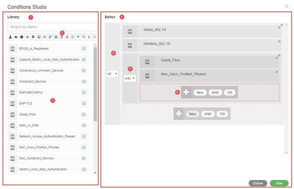
The Condition Studio is divided into two main parts: the Library and the Editor. The Library stores condition blocks for reuse while the Editor enables you to edit those saved blocks and create new ones.
The following table describes the different parts of the Conditions Studio:
|
Fields |
Usage Guidelines |
|---|---|
|
Library |
Displays the list of all condition blocks that were created and saved in the ISE database for reuse. To use these condition blocks as part of your currently edited condition, drag and drop them from the Library to the relevant level in the Editor and update the operators as necessary. Conditions stored in the Library are all represented by the Library icon Next to each condition in the Library you can also find the i icon. Hover over this icon to view a full description of the condition, view the categories to which it is associated, and to delete the condition from the library entirely. You cannot delete conditions if they are used by policies. Drag and drop any of the Library conditions into the Editor in order to use it for the currently edited policy on its own or as a building block for a more complex condition to be used in the current policy or saved as a new condition in the Library. You can also drag and drop the condition in the Editor in order to make changes to that condition and then save it under the same or a new name in the Library. There are also predefined conditions upon installation. These conditions can also be changed and deleted. |
|
Search and filter |
Search conditions by name or filter them by category. In a similar manner, you can also search and filter attributes from the Click to add an attribute field in the Editor. The icons on the toolbar represent different attribute categories such as subject, address and so forth. Click an icon to view attributes related to the specific category and click a highlighted icon from the category toolbar in order to deselect it, thereby removing the filter. |
|
Conditions List |
The complete list of all conditions in the Library, or the list of conditions in the Library based on the search or filter results. |
|
Editor |
Create new conditions to use immediately as well as to save them in the system Library for future use, and edit existing conditions and save those changes in the Library for immediate and future use. When opening the Conditions Studio in order to create a new condition (click the plus sign from any of the policy set tables), the Editor appears with only a single, empty, line to which you can add your first rule. When the Editor opens with empty fields, no operator icons appear |
|
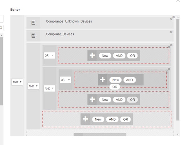
The Editor is divided into different virtual columns and rows. Columns represent different hierarchical levels, and each column is indented based on its position in the hierarchy; rows represent individual rules. You can create single or multiple rules per level, and you can include multiple levels. The example in the image above displays a condition that is in the process of being built or edited and includes a hierarchy of rules, where both the first and second levels in the figure are marked with the number 5. The rules on the top parent level use the operator OR. In order to change the operator once you have selected it and created the hierarchical level, simply select the relevant option from the dropdown list that appears in this column. In addition to the operator dropdown list, each rule has a relevant icon in this column, indicating what category it belongs to. If you hover over the icon, a tooltip indicates the name of the category. Once saved to the library, all condition blocks are assigned the Library icon, replacing the category icons that appeared in the Editor. Finally, if a rule is configured to exclude all relevant matched items, then the Is-Not indicator also appears in this column. For example, if a location attribute with the value London is set to Is-Not then all devices from London will be denied access. |
|
|
This area displays the options available when working with hierarchical levels as well as multiple rules within a condition. When you hover over any column or row the relevant actions appear. When you select an action, it is applied to that section and all of the children sections. For example, with five levels in Hierarchy A, if you choose AND from any rule in the third level, then a new hierarchy, Hierarchy B, is created under the original rule so that the original rule becomes the parent rule for Hierarchy B, which is embedded in Hierarchy A. When you first open the Condition Studio in order to create a new condition from scratch, the Editor area includes only one line for a single rule that you can configure, as well as the option to select relevant operators or to drag and drop relevant conditions from the Library. Additional levels can be added to the condition with the AND and OR operator options. Choose New to create a new rule on the same level from which you clicked the option. The New option only appears once you have configured at least one rule on the top level of the hieararchy. |
 , because conditions can be associated with more than one category.
Configure, Edit and Manage Policy Conditions
When creating new conditions, you can use the condition blocks that you have already stored in the Library and you can also update and change those stored condition blocks. While creating and managing conditions, easily find the blocks and attributes that you need by using quick category filters, and more.
When creating and managing condition rules, use attributes, operators and values.
Cisco ISE also includes predefined condition blocks for some of the most common use cases. You can edit these predefined conditions to suit your requirements. Conditions saved for re-use, including the out-of-the-box blocks, are stored in the Library of the Condition Studio, as described in this task.
To perform the following task, you must be a Super Admin or Policy Admin.
Procedure
| Step 1 |
Access the Policy Sets area. Choose . |
||||||||||||
| Step 2 |
Access the Conditions Studio to create a new condition and to edit existing condition blocks, in order to then use those conditions as part of the rules you configure for the specific policy set (and its associated policies and rules), or in order to save to the Library for future use:
The Conditions Studio opens. If you have opened it in order to create new conditions, then it appears as in the following image. For a description of the fields and to see an example of the Conditions Studio when you have opened it to edit conditions that were already applied to the policy set, see Navigate the Conditions Studio. 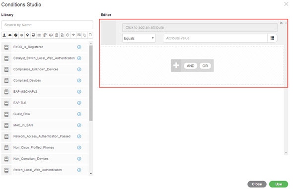 |
||||||||||||
| Step 3 |
Use an existing condition block from the Library as a rule in the condition that you are creating or editing. |
||||||||||||
| Step 4 |
Add an operator to the current level in order to then add additional rules on the same level—choose AND, OR or Set to 'Is not'. Set to 'Is not' can also be applied to individual rules. |
||||||||||||
| Step 5 |
Create and edit rules using the attribute dictionaries—click in the Click to add an attribute field. The Attribute Selector opens as in the following image: 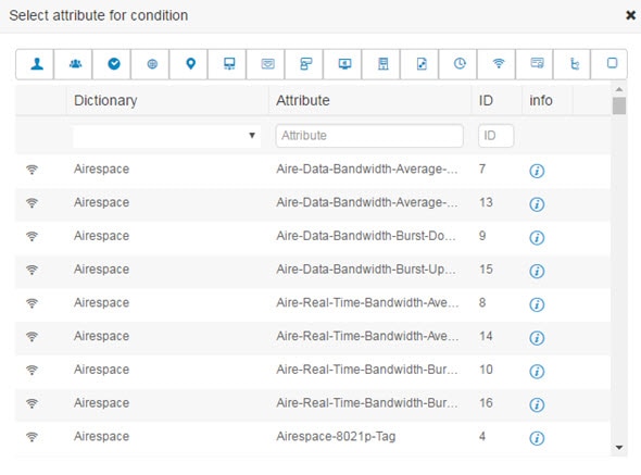 The parts of the Attribute Selector are as described in the following table:
|
||||||||||||
| Step 6 |
Save rules in the Library as a condition block. |
||||||||||||
| Step 7 |
To create a new rule on a new child level—click AND or OR to apply the correct operator between the existing parent hierarchy and the child hierarchy that you are creating. A new section is added to the Editor hierarchy with the selected operator, as a child of the rule or hierarchy from which you chose the operator. |
||||||||||||
| Step 8 |
To create a new rule on a a current existing level—click New from the relevant level. A new empty row appears for a new rule in the same level as the level from which you began. |
||||||||||||
| Step 9 |
Click X to remove any condition from the Editor and all of its children. |
||||||||||||
| Step 10 |
Click Duplicate to automatically copy and paste the specific condition within the hierarchy, thereby creating additional identical children at the same level. You can duplicate individual rules with or without their children, depending on the level from which you click the Duplicate button. |
||||||||||||
| Step 11 |
Click Use from the bottom of the page to save the condition you created in the Editor and to implement that condition in your policy set. |
Special Network Access Conditions
This section describes unique conditions that can be useful when creating your policy sets. These conditions cannot be created from the Conditions Studio and so have their own unique processes.
Configure Device Network Conditions
Procedure
| Step 1 |
Choose Policy > Policy Elements > Conditions > Network Conditions > Device Network Conditions. |
| Step 2 |
Click Add. |
| Step 3 |
Enter a name and description for the network condition. |
| Step 4 |
Enter the following details:
|
| Step 5 |
Click Submit. |
Configure Device Port Network Condition
Procedure
| Step 1 |
Choose Policy > Policy Elements > Conditions > Network Conditions > Device Port Network Conditions. |
| Step 2 |
Click Add. |
| Step 3 |
Enter a name and description for the network condition. |
| Step 4 |
Enter the following details:
|
| Step 5 |
Click Submit. |
Configure Endstation Network Conditions
Procedure
| Step 1 |
Choose Policy > Policy Elements > Conditions > Network Conditions > Endstation Network Conditions. |
| Step 2 |
Click Add. |
| Step 3 |
Enter a name and description for the network condition. |
| Step 4 |
Enter the following details:
|
| Step 5 |
Click Submit. |
Create Time and Date Conditions
Use the Policy Elements Conditions page to display, create, modify, delete, duplicate, and search time and date policy element conditions. Policy elements are shared objects that define a condition that is based on specific time and date attribute settings that you configure.
Time and date conditions let you set or limit permission to access Cisco ISE system resources to specific times and days as directed by the attribute settings you make.
Before you begin
To perform the following task, you must be a Super Admin or Policy Admin.
Procedure
| Step 1 |
Choose . |
| Step 2 |
Enter appropriate values in the fields.
|
| Step 3 |
Click Submit. |
Use IPv6 Condition Attributes in Authorization Policies
Cisco ISE can detect, manage, and secure IPv6 traffic from endpoints.
When an IPv6-enabled endpoint connects to the Cisco ISE network, it communicates with the Network Access Device (NAD) over an IPv6 network. The NAD conveys the accounting and profiling information from the endpoint (including IPv6 values) to Cisco ISE over an IPv4 network. You can configure authorization profiles and policies in Cisco ISE using the IPv6 attributes in your rule conditions in order to process such requests from IPv6-enabled endpoints and ensure that the endpoint is compliant.
Wildcard characters are supported in IPv6 prefix and IPv6 interface values. For example: 2001:db8:1234::/48.
Supported IPv6 address formats include:
-
Full notation: Eight groups of four hexadecimal digits separated by colons. For example, 2001:0db8:85a3:0000:0000:8a2e:0370:7334
-
Shortened notation: Exclude leading zeros in a group; replace groups of zeros with two consecutive colons. For example: 2001:db8:85a3::8a2e:370:7334
-
Dotted-quad notation (IPv4-mapped and IPv4 compatible-IPv6 addresses): For example, ::ffff:192.0.2.128
Supported IPv6 attributes include:
-
NAS-IPv6-Address
-
Framed-Interface-Id
-
Framed-IPv6-Prefix
-
Login-IPv6-Host
-
Framed-IPv6-Route
-
Framed-IPv6-Pool
-
Delegated-IPv6-Prefix
-
Framed-IPv6-Address
-
DNS-Server-IPv6-Address
-
Route-IPv6-Information
-
Delegated-IPv6-Prefix-Pool
-
Stateful-IPv6-Address-Pool
Supported Cisco Attribute-Value pairs and their equivalent IETF attributes are listed in the table below:
|
Cisco Attribute-Value Pairs |
IETF Attributes |
|---|---|
|
ipv6:addrv6=<ipv6 address> |
Framed-ipv6-Address |
|
ipv6:stateful-ipv6-address-pool=<name> |
Stateful-IPv6-Address-Pool |
|
ipv6:delegated-ipv6-pool=<name> |
Delegated-IPv6-Prefix-Pool |
|
ipv6:ipv6-dns-servers-addr=<ipv6 address> |
DNS-Server-IPv6-Address |
The RADIUS Live Logs page, RADIUS Authentication report, RADIUS Accounting report, Current Active Session report, RADIUS Error report, Misconfigured NAS report, EPS Audit report, and Misconfigured Supplicant report support IPv6 addresses. You can view the details about these sessions from the RADIUS Live Logs page or from any of these reports. You can filter the records based on IPv4, IPv6, or MAC addresses.
Note |
If you connect an Android device to an IPv6 enabled DHCPv6 network, it receives only the link-local IPv6 address from the DHCP server. Hence, global IPv6 address is not displayed in the Live Logs and in the Endpoints page (). |
The following procedure describes how to configure IPv6 attributes in authorization policies.
Before you begin
Ensure that the NADs in your deployment support AAA with IPv6. Refer to AAA Support for IPv6 for information on how to enable AAA support for IPv6 on your NADs.
Procedure
| Step 1 |
For network access policies, choose . For device administration policies, choose . |
| Step 2 |
Create authorization rules. |
| Step 3 |
When creating authorization rules, create a condition from the Conditon Studio. In the Condition Studio, from the RADIUS dictionary, choose the RADIUS IPv6 attribute, the operator, and the value. |
| Step 4 |
Click Save to save the authorization rules in the policy set. |
Policy Set Protocol Settings
You must define global protocol settings in Cisco ISE before you can use these protocols to create, save and implement a policy set. You can use the Protocol Settings page to define global options for the Extensible Authentication Protocol-Flexible Authentication via Secure Tunneling (EAP-FAST), Extensible Authentication Protocol-Transport Layer Security (EAP-TLS), and Protected Extensible Authentication Protocol (PEAP) protocols, which communicate with the other devices in your network.
Supported Network Access Policy Set Protocols
The following is a list of protocols that you can choose while defining your Network Access Policy Set policy:
-
Password Authentication Protocol (PAP)
-
Protected Extensible Authentication Protocol (PEAP)
-
Microsoft Challenge Handshake Authentication Protocol Version 2 (MS-CHAPv2)
-
Extensible Authentication Protocol-Message Digest 5 (EAP-MD5)
-
Extensible Authentication Protocol-Transport Layer Security (EAP-TLS)
-
Extensible Authentication Protocol-Flexible Authentication via Secure Tunneling (EAP-FAST)
-
Extensible Authentication Protocol-Tunneled Transport Layer Security (EAP-TTLS)
-
Protected Extensible Authentication Protocol-Transport Layer Security (PEAP-TLS)
Guidelines for Using EAP-FAST as Protocol
Follow these guidelines when using EAP-FAST as an authentication protocol:
-
It is highly recommended to enable EAP-TLS inner method when the EAP-FAST accept client certificate is enabled on authenticated provisioning. EAP-FAST accept client certificate on authenticated provisioning is not a separate authentication method but a shorter form of client certificate authentication that uses the same certificate credentials type to authenticate a user but does not require to run an inner method.
-
Accept client certificate on authenticated provisioning works with PAC-less full handshake and authenticated PAC provisioning. It does not work for PAC-less session resume, anonymous PAC provisioning, and PAC-based authentication.
-
EAP attributes are displayed per identity (so in EAP chaining displayed twice) are shown in authentication details in monitoring tool in order user then machine even if authentication happens in different order.
-
When EAP-FAST authorization PAC is used then EAP authentication method shown in live logs is equal to the authentication method used for full authentication (as in PEAP) and not as Lookup.
-
In EAP chaining mode when tunnel PAC is expired then ISE falls back to provisioning and AC requests User and Machine authorization PACs - Machine Authorization PAC cannot be provisioned. It will be provisioned in the subsequent PAC-based authentication conversation when AC requests it.
-
When Cisco ISE is configured for chaining and AC for single mode then AC response with IdentityType TLV to ISE. However, the second identity authentication fails. You can see from this conversation that client is suitable to perform chaining but currently is configured for single mode.
-
Cisco ISE supports retrieval attributes and groups for both machine and user in EAP-FAST chaining only for AD. For LDAP and Internal DB ISE uses only the last identity attributes.
Note |
“EAP-FAST cryptobinding verification failed” message might be seen if EAP-FAST authentication protocol is used for High Sierra MAC OSX devices. We recommend that you configure the Preferred EAP Protocol field in the Allowed Protocols page to use PEAP or EAP-TLS instead of EAP-FAST for High Sierra MAC OSX devices. |
Configure EAP-FAST Settings
Before you begin
To perform the following task, you must be a Super Admin or System Admin.
Procedure
| Step 1 |
Choose . |
| Step 2 |
Enter the details as required to define the EAP-FAST protocol. |
| Step 3 |
Click Revoke if you want to revoke all the previously generated master keys and PACs. |
| Step 4 |
Click Save to save the EAP-FAST settings. |
Generate the PAC for EAP-FAST
You can use the Generate PAC option in the Cisco ISE to generate a tunnel or machine PAC for the EAP-FAST protocol.
Before you begin
To perform the following task, you must be a Super Admin or System Admin.
Procedure
| Step 1 |
Choose . |
| Step 2 |
From the Settings navigation pane on the left, click Protocols. |
| Step 3 |
Choose . |
| Step 4 |
Enter the details as required to generate machine PAC for the EAP-FAST protocol. |
| Step 5 |
Click Generate PAC. |
EAP-FAST Settings
The following table describes the fields on the Protocol Settings page, which you can use to configure the EAP-FAST, EAP-TLS, and PEAP protocols. The navigation path for this page is: .
|
Fields |
Usage Guidelines |
|---|---|
|
Authority Identity Info Description |
Enter a user-friendly string that describes the Cisco ISE node that sends credentials to a client. The client can discover this string in the Protected Access Credentials (PAC) information for type, length, and value (TLV). The default value is Identity Services Engine. |
|
Master Key Generation Period |
Specifies the master key generation period in seconds, minutes, hours, days, or weeks. The value must be a positive integer in the range 1 to 2147040000 seconds. The default is 604800 seconds, which is equivalent to one week. |
|
Revoke all master keys and PACs |
Click Revoke to revoke all master keys and PACs. |
|
Enable PAC-less Session Resume |
Check this check box if you want to use EAP-FAST without the PAC files. |
|
PAC-less Session Timeout |
Specifies the time in seconds after which the PAC-less session resume times out. The default is 7200 seconds. |
PAC Settings
| Fields | Usage Guidelines |
|---|---|
|
Tunnel PAC |
Click this radio button to generate a tunnel PAC. |
|
Machine PAC |
Click this radio button to generate a machine PAC. |
|
Trustsec PAC |
Click this radio button to generate a Trustsec PAC. |
|
Identity |
(For the Tunnel and Machine PAC identity field) Specifies the username or machine name that is presented as the “inner username” by the EAP-FAST protocol. If the identity string does not match that username, authentication fails. This is the hostname as defined on the Adaptive Security Appliance (ASA). The identity string must match the ASA hostname otherwise, ASA cannot import the PAC file that is generated. If you are generating a Trustsec PAC, the Identity field specifies the Device ID of a Trustsec network device and is provided with an initiator ID by the EAP-FAST protocol. If the Identity string entered here does not match that Device ID, authentication fails. |
|
PAC Time to Live |
(For the Tunnel and Machine PAC) Enter a value in seconds that specifies the expiration time for the PAC. The default is 604800 seconds, which is equivalent to one week. This value must be a positive integer between 1 and 157680000 seconds. For the Trustsec PAC, enter a value in days, weeks, months, or years. By default, the value is one year. The minimum value is one day and the maximum is 10 years. |
|
Encryption Key |
Enter an encryption key. The length of the key must be between 8 and 256 characters. The key can contain uppercase or lowercase letters, or numbers, or a combination of alphanumeric characters. |
|
Expiration Data |
(For Trustsec PAC only) The expiration date is calculated based on the PAC Time to Live. |
Using EAP-TTLS as Authentication Protocol
EAP-TTLS is a two-phase protocol that extends the functionality of EAP-TLS protocol. Phase 1 builds the secure tunnel and derives the session keys used in Phase 2 to securely tunnel attributes and inner method data between the server and the client. You can use the attributes tunneled during Phase 2 to perform additional authentications using a number of different mechanisms.
Cisco ISE can process authentications from a variety of TTLS supplicants including:
-
AnyConnect Network Access Manager (NAM) on Windows
-
Windows 8.1 native supplicant
-
Secure W2 (also called as JoinNow on MultiOS)
-
MAC OS X native supplicant
-
IOS native supplicant
-
Android based native supplicant
-
Linux WPA supplicant
Note |
If cryptobinding is required, you must use EAP-FAST as the inner method. |
Configure EAP-TTLS Settings
Before you begin
To perform the following task, you must be a Super Admin or System Admin.
Procedure
| Step 1 |
Choose Administration > System > Settings > Protocols > EAP-TTLS. |
| Step 2 |
Enter the required details in the EAP-TTLS Settings page. |
| Step 3 |
Click Save. |
EAP-TTLS Settings
The following table describes the fields on the EAP-TTLS Settings page. The navigation path for this page is: Administration > System > Settings > Protocols > EAP-TTLS.
|
Fields |
Usage Guidelines |
||
|---|---|---|---|
|
Enable EAP-TTLS Session Resume |
If you check this check box, Cisco ISE will cache the TLS session that is created during phase one of EAP-TTLS authentication, provided the user successfully authenticates in phase two of EAP-TTLS. If a user needs to reconnect and the original EAP-TTLS session has not timed out, Cisco ISE uses the cached TLS session, resulting in faster EAP-TTLS performance and a reduced AAA server load.
|
||
|
EAP-TTLS Session Timeout |
Specifies the time in seconds after which the EAP-TTLS session times out. The default value is 7200 seconds. |
Configure EAP-TLS Settings
Before you begin
To perform the following task, you must be a Super Admin or System Admin.
Procedure
| Step 1 |
Choose . |
| Step 2 |
Enter the details as required to define the EAP-TLS protocol. |
| Step 3 |
Click Save to save the EAP-TLS settings. |
EAP-TLS Settings
| Fields | Usage Guidelines |
|---|---|
|
Enable EAP-TLS Session Resume |
Check this check box to support an abbreviated reauthentication of a user who has passed full EAP-TLS authentication. This feature provides reauthentication of the user with only a Secure Sockets Layer (SSL) handshake and without applying the certificates. EAP-TLS session resume works only if the EAP-TLS session has not timed out. |
|
EAP-TLS Session Timeout |
Specifies the time in seconds after which the EAP-TLS session times out. The default value is 7200 seconds. |
|
Stateless Session Resume |
|
|
Master Key Generation Period |
Enter the time after which the master key is regenerated. This value determines the duration that a master key remains active. You can enter the value in seconds, minutes, hours, days, or weeks. |
|
Revoke |
Click Revoke to cancel all previously generated master keys and tickets. This option is disabled on the secondary node. |
Configure PEAP Settings
Before you begin
To perform the following task, you must be a Super Admin or System Admin.
Procedure
| Step 1 |
Choose . |
| Step 2 |
From the Settings navigation pane on the left, click Protocols. |
| Step 3 |
Choose PEAP. |
| Step 4 |
Enter the details as required to define the PEAP protocol. |
| Step 5 |
Click Save to save the PEAP settings. |
PEAP Settings
| Fields | Usage Guidelines |
|---|---|
|
Enable PEAP Session Resume |
Check this check box for the Cisco ISE to cache the TLS session that is created during phase one of PEAP authentication, provided the user successfully authenticates in phase two of PEAP. If a user needs to reconnect and the original PEAP session has not timed out, the Cisco ISE uses the cached TLS session, resulting in faster PEAP performance and a reduced AAA server load. You must specify a PEAP session timeout value for the PEAP session resume features to work. |
|
PEAP Session Timeout |
Specifies the time in seconds after which the PEAP session times out. The default value is 7200 seconds. |
|
Enable Fast Reconnect |
Check this check box to allow a PEAP session to resume in the Cisco ISE without checking user credentials when the session resume feature is enabled. |
Configure RADIUS Settings
You can configure the RADIUS settings to detect the clients that fail to authenticate and to suppress the repeated reporting of successful authentications.
Procedure
| Step 1 |
Choose . |
| Step 2 |
From the Settings navigation pane, click Protocols. |
| Step 3 |
Choose RADIUS. |
| Step 4 |
Enter the details as required to define the RADIUS settings. |
| Step 5 |
Click Save to save the settings. |
RADIUS Settings
The following table describes the fields on the RADIUS Settings page. The navigation path for this page is:.
If you enable the Suppress Repeated Failed Clients option, clients with repeated authentication failures will be suppressed from the audit logs, and the requests from these clients will be automatically rejected for the specified time period. You can also specify the number of authentication failures after which the requests from these clients should be rejected. For example, if this value is configured as 5, when a client authentication fails five times, all the requests received from that client will be rejected for the configured time period.
|
Fields |
Usage Guidelines |
||
|---|---|---|---|
|
Suppress Repeated Failed Clients |
|||
|
Suppress Repeated Failed Clients |
Check this check box to suppress the clients for which the authentications fail repeatedly for the same reason. These clients are suppressed from the audit logs and the requests from these clients are rejected for the specified time period if Reject RADIUS Requests from Clients with Repeated Failures option is enabled. |
||
|
Detect Two Failures Within |
Enter the time interval in minutes. If a client fails authentication twice for the same reason within this time period, it will be suppressed from the audit logs, and the requests from this client will be rejected if Reject RADIUS Requests from Clients with Repeated Failures option is enabled. |
||
|
Report Failures Once Every |
Enter the time interval in minutes for the failed authentications to be reported. For example, if this value is set as 15 minutes, clients that repeatedly fail authentication will be reported in the audit logs only once every 15 minutes, thereby preventing over-reporting. |
||
|
Reject RADIUS Requests from Clients with Repeated Failures |
Check this check box to automatically reject the RADIUS requests from the clients for which the authentications fail repeatedly. You can enable this option to avoid unnecessary processing by Cisco ISE and to protect against potential denial of service attacks. |
||
|
Failures Prior to Automatic Rejection |
Enter the number of authentication failures after which requests from clients with repeated failures are automatically rejected. All the requests received from these clients are automatically rejected for the configured time period (specified in Continue Rejecting Requests for field). After the interval expires, the authentication requests from these clients are processed. | ||
|
Continue Rejecting Requests for |
Enter the time interval (in minutes) for which the requests from clients with repeated failures are to be rejected. |
||
|
Ignore Repeated Accounting Updates Within |
Repeated accounting updates that occur within this period will be ignored. |
||
| Suppress Successful Reports | |||
|
Suppress Repeated Successful Authentications |
Check this check box to prevent repeated reporting of successful authentication requests in last 24 hours that have no change in identity context, network device, and authorization. |
||
|
Authentications Details |
|||
|
Highlight Steps Longer Than |
Enter the time interval in milliseconds. If execution of a single step exceeds the specified threshold, it will be marked with a clock icon in the authentication details page. |
||
|
Disclose Invalid Usernames |
Check this checkbox to disclose the usernames labelled as 'USERNAME' or 'INVALID' in the Radius Live Logs. You can then view the logged in username in the Radius Live Logs as well as in the Authentication Summary Report. This option will be disabled automatically after 30 minutes. |
||
|
RADIUS UDP Ports |
|||
|
Authentication Ports |
Specify the ports to be used for RADIUS UDP authentication flows. You can specify a maximum of 4 port numbers (separated by a comma). By default, port 1812 and port 1645 are used. The valid range is from 1024 to 65535. |
||
|
Accounting Ports |
Specify the ports to be used for RADIUS UDP accounting flows. You can specify a maximum of 4 port numbers (separated by a comma). By default, port 1813 and port 1646 are used. The valid range is from 1024 to 65535.
|
||
|
RADIUS DTLS |
|||
|
Authentication and Accounting Port |
Specify the port to be used for RADIUS DTLS authentication and accounting flows. By default, port 2083 is used. The valid range is from 1024 to 65535.
|
||
|
Idle Timeout |
Enter the time (in seconds) that you want Cisco ISE to wait before it closes the TLS session if no packets are received from the network device. Default value is 120 seconds. The valid range is from 60 to 600 seconds. |
||
|
Enable RADIUS/DTLS Client Identity Verification |
Check this check box if you want Cisco ISE to verify the identity of the RADIUS/DTLS clients during the DTLS handshake. Cisco ISE fails the handshake if the client identity is not valid. Identity check is skipped for the default network device, if configured. Identity check is performed in the following sequence:
|
||
Configure Security Settings
To configure the security settings:
Procedure
| Step 1 |
Choose Administration > System > Settings > Protocols > Security Settings. |
||
| Step 2 |
On the Security Settings page, select the required options:
|
||
| Step 3 |
Click Save. |
RADIUS Protocol Support in Cisco ISE
RADIUS is a client/server protocol through which remote-access servers communicate with a central server to authenticate dial-in users and authorize their access to the requested system or service. You can use RADIUS to maintain user profiles in a central database that all remote servers can share. This protocol provides better security, and you can use it to set up a policy that is applied at a single administered network point.
RADIUS also functions as a RADIUS client in Cisco ISE to proxy requests to a remote RADIUS server, and it provides Change of Authorization (CoA) activities during an active session.
Cisco ISE supports RADIUS protocol flow according to RFC 2865 and generic support for all general RADIUS attributes as described in RFC 2865 and its extension. Cisco ISE supports parsing of vendor-specific attributes only for vendors that are defined in the Cisco ISE dictionary.
RADIUS interface supports the following attribute data types that are defined in RFC 2865:
-
Text (Unicode Transformation Format [UTF])
-
String (binary)
-
Address (IP)
-
Integer
-
Time
|
For information about the network access attributes supported by Cisco ISE, see ISE Network Access Attributes. |
Allowed Protocols
The following table describes the fields in the Allowed Protocols page, which allows you to configure the protocols to be used during authentication. The navigation path for this page is: .
In the following table, PAC stands for Protected Access Credentials.
|
Fields |
Usage Guidelines |
||
|---|---|---|---|
|
Allowed Protocols > Authentication Bypass |
|||
|
Process Host Lookup |
Check this check box if you want Cisco ISE to process the Host Lookup request. The Host Lookup request is processed for PAP/CHAP protocol when the RADIUS Service-Type equals 10 (Call-Check) and the username is equal to Calling-Station-ID. The Host Lookup request is processed for EAP-MD5 protocol when the Service-Type equals 1 (Framed) and the username is equal to Calling-Station-ID. Uncheck this check box if you want Cisco ISE to ignore the Host Lookup request and use the original value of the system username attribute for authentication. When unchecked, message processing is done according to the protocol (for example, PAP).
|
||
|
Allowed Protocols > Authentication Protocols |
|||
|
Allow PAP/ASCII |
This option enables PAP/ASCII. PAP uses cleartext passwords (that is, unencrypted passwords) and is the least secure authentication protocol. |
||
|
Allow CHAP |
This option enables CHAP authentication. CHAP uses a challenge-response mechanism with password encryption. CHAP does not work with Microsoft Active Directory. |
||
|
Allow MS-CHAPv1 |
Check this check box to enable MS-CHAPv1. |
||
|
Allow MS-CHAPv2 |
Check this check box to enable MS-CHAPv2. |
||
|
Allow EAP-MD5 |
Check this check box to enable EAP-based MD5 password hashed authentication. |
||
|
Allow EAP-TLS |
Check this check box to enable EAP-TLS Authentication protocol and configures EAP-TLS settings. You can specify how Cisco ISE will verify the user identity as presented in the EAP identity response from the end-user client. User identity is verified against information in the certificate that the end-user client presents. This comparison occurs after an EAP-TLS tunnel is established between Cisco ISE and the end-user client.
|
||
|
Allow LEAP |
Check this check box to enable Lightweight Extensible Authentication Protocol (LEAP) authentication. |
||
|
Allow PEAP |
Check this check box to enable PEAP authentication protocol and PEAP settings. The default inner method is MS-CHAPv2. When you check the Allow PEAP check box, you can configure the following PEAP inner methods:
|
||
|
Allow EAP-FAST |
Check this check box to enable EAP-FAST authentication protocol and EAP-FAST settings. The EAP-FAST protocol can support multiple internal protocols on the same server. The default inner method is MS-CHAPv2. When you check the Allow EAP-FAST check box, you can configure EAP-FAST as the inner method:
|
||
|
Allow EAP-TTLS |
Check this check box to enable EAP-TTLS protocol. You can configure the following inner methods:
|
||
|
Preferred EAP Protocol |
Check this check box to choose your preferred EAP protocols from any of the following options: EAP-FAST, PEAP, LEAP, EAP-TLS, EAP-TTLS, and EAP-MD5. If you do not specify the preferred protocol, EAP-TLS is used by default. |
||
|
EAP-TLS L-bit |
Check this check box to support legacy EAP supplicants that expect L-bit flag (length- included flag) by default in TLS Change Cipher Spec message and Encrypted Handshake message from ISE. |
||
|
Allow Weak Ciphers for EAP |
If this option is enabled, legacy clients are allowed to negotiate using weak ciphers (such as RSA_RC4_128_SHA, RSA_RC4_128_MD5). We recommend that you enable this option only if your legacy clients support only weak ciphers. This option is disabled by default.
|
||
|
Require Message Authenticator for all RADIUS Requests |
If this option is enabled, Cisco ISE verifies whether the RADIUS Message Authenticator attribute is present in the RADIUS message. If the message authenticator attribute is not present, the RADIUS message is discarded. Enabling this option provides protection from spoofed Access-Request messages and RADIUS message tampering. The RADIUS Message Authenticator attribute is a Message Digest 5 (MD5) hash of the entire RADIUS message.
|
||
PAC Options
The following table describes the fields after you select Use PACs in the Allowed Protocols Services List page. The navigation path for this page is: .
|
Fields |
Usage Guidelines |
|---|---|
|
Use PAC |
|
Cisco ISE Acting as a RADIUS Proxy Server
Cisco ISE can function both as a RADIUS server and as a RADIUS proxy server. When it acts as a proxy server, Cisco ISE receives authentication and accounting requests from the network access server (NAS) and forwards them to the external RADIUS server. Cisco ISE accepts the results of the requests and returns them to the NAS.
Cisco ISE can simultaneously act as a proxy server to multiple external RADIUS servers. You can use the external RADIUS servers that you configure here in RADIUS server sequences. The External RADIUS Server page lists all the external RADIUS servers that you have defined in Cisco ISE. You can use the filter option to search for specific RADIUS servers based on the name or description, or both. In both simple and rule-based authentication policies, you can use the RADIUS server sequences to proxy the requests to a RADIUS server.
The RADIUS server sequence strips the domain name from the RADIUS-Username attribute for RADIUS authentications. This domain stripping is not applicable for EAP authentications, which use the EAP-Identity attribute. The RADIUS proxy server obtains the username from the RADIUS-Username attribute and strips it from the character that you specify when you configure the RADIUS server sequence. For EAP authentications, the RADIUS proxy server obtains the username from the EAP-Identity attribute. EAP authentications that use the RADIUS server sequence will succeed only if the EAP-Identity and RADIUS-Username values are the same.
Configure External RADIUS Servers
You must configure the external RADIUS servers in the Cisco ISE to enable it to forward requests to the external RADIUS servers. You can define the timeout period and the number of connection attempts.
Before you begin
-
You cannot use the external RADIUS servers that you create in this section by themselves. You must create a RADIUS server sequence and configure it to use the RADIUS server that you create in this section. You can then use the RADIUS server sequence in authentication policies.
-
To perform the following task, you must be a Super Admin or System Admin.
Procedure
| Step 1 |
Choose . The RADIUS Servers page appears with a list of external RADIUS servers that are defined in Cisco ISE. |
| Step 2 |
Click Add to add an external RADIUS server. |
| Step 3 |
Enter the values as required. |
| Step 4 |
Click Submit to save the external RADIUS server configuration. |
Define RADIUS Server Sequences
RADIUS server sequences in Cisco ISE allow you to proxy requests from a NAD to an external RADIUS server that will process the request and return the result to Cisco ISE, which forwards the response to the NAD.
RADIUS Server Sequences page lists all the RADIUS server sequences that you have defined in Cisco ISE. You can create, edit, or duplicate RADIUS server sequences from this page.
Before you begin
-
Before you begin this procedure, you should have a basic understanding of the Proxy Service and must have successfully completed the task in the first entry of the Related Links.
-
To perform the following task, you must be a Super Admin or System Admin.
Procedure
| Step 1 |
Choose . |
| Step 2 |
Click Add. |
| Step 3 |
Enter the values as required. |
| Step 4 |
Click Submit to save the RADIUS server sequence to be used in policies. |
Cisco ISE Acting as a TACACS+ Proxy Client
Cisco ISE can act as proxy client to external TACACS+ servers. When it acts as a proxy client, Cisco ISE receives authentication, authorization, and accounting requests from the Network Access Server (NAS) and forwards them to the external TACACS+ server. Cisco ISE accepts the results of the requests and returns them to the NAS.
The TACACS+ External Servers page lists all the external TACACS+ servers that you have defined in Cisco ISE. You can use the filter option to search for specific TACACS+ servers based on the name or description, or both.
Cisco ISE can simultaneously act as a proxy client to multiple external TACACS+ servers. In order to configure multiple external servers, you can use the TACACS+ server sequence page. Refer to the TACACS+ Server Sequence Settings page for more information.
Configure External TACACS+ Servers
You must configure the external TACACS servers in the Cisco ISE to enable it to forward requests to the external TACACS servers. You can define the timeout period and the number of connection attempts.
Before you begin
-
You cannot use the external TACACS servers that you create in this section directly in the policy. You must create a TACACS server sequence and configure it to use the TACACS server that you create in this section. You can then use the TACACS server sequence in the policy sets.
-
To perform the following task, you must be a Super Admin or System Admin.
Procedure
| Step 1 |
Choose . The
TACACS
External Servers page appears with a list of external TACACS
servers that are defined in Cisco ISE.
|
| Step 2 |
Click Add to add an external TACACS server. |
| Step 3 |
Enter the values as required. |
| Step 4 |
Click Submit to save the external TACACS server configuration. |
TACACS+ External Server Settings
The following table describes the fields in the TACACS External Servers page. The navigation path is page.
|
Fields |
Usage Guidelines |
|---|---|
|
Name |
Enter the name of the TACACS+ external server. |
|
Description |
Enter a description for the TACACS+ external server setting. |
|
Host IP |
Enter the IP address (IPv4 or IPv6 address) of the remote TACACS+ external server. |
|
Connection Port |
Enter the port number of the remote TACACS+ external server. The port number is 49. |
|
Timeout |
Specify the number of seconds that ISE should wait for a response from the external TACACS+ server. The default is 5 seconds. Valid values are from 1 to 120. |
|
Shared Secret |
A string of text that is used to secure a connection with the TACACS+ External Server. The connection will be rejected by the TACACS+ External server if this is not configured correctly. |
|
Use Single Connect |
The TACACS protocol supports two modes for associating sessions to connections: Single Connect and Non-Single Connect. Single connect mode reuses a single TCP connection for many TACACS+ sessions that a client may initiate. Non-Single Connect opens a new TCP connection for every TACACS+ session that a client initiates. The TCP connection is closed after each session. You can check the Use Single Connect check box for high-traffic environment and uncheck it for low-traffic environment. |
Define TACACS+ Server Sequences
TACACS+ server sequences in Cisco ISE allow you to proxy requests from a NAD to an external TACACS+ server that will process the request and return the result to Cisco ISE, which forwards the response to the NAD. The TACACS+ Server Sequences page lists all the TACACS+ server sequences that you have defined in Cisco ISE. You can create, edit, or duplicate TACACS+ server sequences from this page.
Before you begin
-
You should have a basic understanding of the Proxy Service, Cisco ISE Admin Groups, Access Levels, Permissions, and Restrictions.
-
To perform the following task, you must be a Super Admin or System Admin.
-
Ensure that the external TACACS+ servers that you intend to use in the TACACS+ server sequence are already defined.
Procedure
| Step 1 |
Choose . |
| Step 2 |
Click Add. |
| Step 3 |
Enter the required values. |
| Step 4 |
Click Submit to save the TACACS+ server sequence to be used in policies. |
TACACS+ Server Sequence Settings
The following table describes the fields in the TACACS Server Sequence page. The navigation path is page.
|
Fields |
Usage Guidelines |
|---|---|
|
Name |
Enter the name of the TACACS proxy server sequence. |
|
Description |
Enter a description for the TACACS proxy server sequence. |
|
Server List |
Select the required TACACS proxy servers from the Available list. The available list contains the list of TACACS proxy servers configured in the TACACS External Services Page. |
|
Logging Control |
Check to
enable logging control:
|
|
Username Stripping |
Username
Prefix/Suffix Stripping:
|
Network Access Service
A network access service contains the authentication policy conditions for requests. You can create separate network access services for different use cases, for example, Wired 802.1X, Wired MAB, and so on. To create a network access service, configure allowed protocols or server sequences. The network access service for network access policies is then configured from the Policy Sets page.
Define Allowed Protocols for Network Access
Allowed protocols define the set of protocols that Cisco ISE can use to communicate with the device that requests access to the network resources. An allowed protocols access service is an independent entity that you should create before you configure authentication policies. Allowed protocols access service is an object that contains your chosen protocols for a particular use case.
The Allowed Protocols Services page lists all the allowed protocols services that you create. There is a default network access service that is predefined in the Cisco ISE.
Before you begin
Before you begin this procedure, you should have a basic understanding of the protocol services that are used for authentication.
-
Review the Cisco ISE Authentication Policies section in this chapter to understand authentication type and the protocols that are supported by various databases.
-
Review the PAC Options to understand the functions and options for each protocol service, so you can make the selections that are appropriate for your network.
-
Ensure that you have defined the global protocol settings.
To perform the following task, you must be a Super Admin or System Admin.
Procedure
| Step 1 |
Choose . If Cisco ISE is set to operate in FIPS mode, some protocols are disabled by default and cannot be configured. |
| Step 2 |
Click Add. |
| Step 3 |
Enter the required information. |
| Step 4 |
Select the appropriate authentication protocols and options for your network. |
| Step 5 |
If you choose to use PACs, make the appropriate selections. To enable Anonymous PAC Provisioning, you must choose both the inner methods, EAP-MSCHAPv2 and Extensible Authentication Protocol-Generic Token Card (EAP-GTC). Also, be aware that Cisco ISE only supports Active Directory as an external identity source for machine authentication. |
| Step 6 |
Click Submit to save the allowed protocols service. The allowed protocols service appears as an independent object in the simple and rule-based authentication policy pages. You can use this object in different rules. You can now create a simple or rule-based authentication policy. If you disable EAP-MSCHAP as inner method and enable EAP-GTC and EAP-TLS inner methods for PEAP or EAP-FAST, ISE starts EAP-GTC inner method during inner method negotiation. Before the first EAP-GTC message is sent to the client, ISE executes identity selection policy to obtain GTC password from the identity store. During the execution of this policy, EAP authentication is equal to EAP-GTC. If EAP-GTC inner method is rejected by the client and EAP-TLS is negotiated, identity store policy is not executed again. In case identity store policy is based on EAP authentication attribute, it might have unexpected results since the real EAP authentication is EAP-TLS but was set after identity policy evaluation. |
Network Access for Users
For network access, a host connects to the network device and requests to use network resources. The network device identifies the newly connected host, and, using the RADIUS protocol as a transport mechanism, requests Cisco ISE to authenticate and authorize the user.
Cisco ISE supports network access flows depending on the protocol that is transported over the RADIUS protocol.
RADIUS-Based Protocols Without EAP
RADIUS-based protocols that do not include EAP include the following:
-
Password Authentication Protocol (PAP)
-
CHAP
-
Microsoft Challenge Handshake Authentication Protocol version 1 (MS-CHAPv1)
-
MS-CHAP version 2 (MS-CHAPv2)
RADIUS-Based Non-EAP Authentication Flow
This section describes RADIUS-based flow without EAP authentication. RADIUS-based flow with PAP authentication occurs in the following process:
-
A host connects to a network device.
-
The network device sends a RADIUS request (Access-Request) to Cisco ISE that contains RADIUS attributes that are appropriate to the specific protocol that is being used (PAP, CHAP, MS-CHAPv1, or MS-CHAPv2).
-
Cisco ISE uses an identity store to validate user credentials.
-
A RADIUS response (Access-Accept or Access-Reject) is sent to the network device that will apply the decision.
The following figure shows a RADIUS-based authentication without EAP.
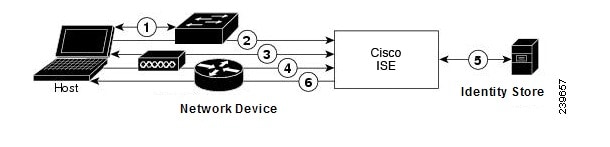
Password Authentication Protocol
PAP provides a simple method for users to establish their identity by using a two-way handshake. The PAP password is encrypted with a shared secret and is the least sophisticated authentication protocol. PAP is not a strong authentication method because it offers little protection from repeated trial-and-error attacks.
RADIUS-Based PAP Authentication in Cisco ISE
Cisco ISE checks the username and password pair against the identity stores, until it eventually acknowledges the authentication or terminates the connection.
You can use different levels of security concurrently with Cisco ISE for different requirements. PAP applies a two-way handshaking procedure. If authentication succeeds, Cisco ISE returns an acknowledgment; otherwise, Cisco ISE terminates the connection or gives the originator another chance.
The originator is in total control of the frequency and timing of the attempts. Therefore, any server that can use a stronger authentication method will offer to negotiate that method prior to PAP. RFC 1334 defines PAP.
Cisco ISE supports standard RADIUS PAP authentication that is based on the RADIUS UserPassword attribute. RADIUS PAP authentication is compatible with all identity stores.
The RADIUS-with-PAP-authentication flow includes logging of passed and failed attempts.
Challenge Handshake Authentication Protocol
CHAP uses a challenge-response mechanism with one-way encryption on the response. CHAP enables Cisco ISE to negotiate downward from the most-secure to the least-secure encryption mechanism, and it protects passwords that are transmitted in the process. CHAP passwords are reusable. If you are using the Cisco ISE internal database for authentication, you can use PAP or CHAP. CHAP does not work with the Microsoft user database. Compared to RADIUS PAP, CHAP allows a higher level of security for encrypting passwords when communicating from an end-user client to the AAA client.
Cisco ISE supports standard RADIUS CHAP authentication that is based on the RADIUS ChapPassword attribute. Cisco ISE supports RADIUS CHAP authentication only with internal identity stores.
Microsoft Challenge Handshake Authentication Protocol Version 1
-
Internal identity stores
-
Microsoft Active Directory identity store
Microsoft Challenge Handshake Authentication Protocol Version 2
-
Internal identity stores
-
Microsoft Active Directory identity store
RADIUS-Based EAP Protocols
EAP provides an extensible framework that supports various authentication types. This section describes the EAP methods supported by Cisco ISE and contains the following topics:
Simple EAP Methods
-
EAP-Message Digest 5
-
Lightweight EAP
EAP Methods That Use Cisco ISE Server Certificate for Authentication
-
PEAP/EAP-MS-CHAPv2
-
PEAP/EAP-GTC
-
EAP-FAST/EAP-MS-CHAPv2
-
EAP-FAST/EAP-GTC
Apart from the methods listed above, there are EAP methods that use certificates for both server and client authentication.
RADIUS-Based EAP Authentication Flow
Whenever EAP is involved in the authentication process, the process is preceded by an EAP negotiation phase to determine which specific EAP method (and inner method, if applicable) should be used. EAP-based authentication occurs in the following process:
-
A host connects to a network device.
-
The network device sends an EAP Request to the host.
-
The host replies with an EAP Response to the network device.
-
The network device encapsulates the EAP Response that it received from the host into a RADIUS Access-Request (using the EAP-Message RADIUS attribute) and sends the RADIUS Access-Request to Cisco ISE.
-
Cisco ISE extracts the EAP Response from the RADIUS packet and creates a new EAP Request, encapsulates it into a RADIUS Access-Challenge (again, using the EAP-Message RADIUS attribute), and sends it to the network device.
-
The network device extracts the EAP Request and sends it to the host.
In this way, the host and Cisco ISE indirectly exchange EAP messages (transported over RADIUS and passed through the network device). The initial set of EAP messages that are exchanged in this manner negotiate the specific EAP method that will subsequently be used to perform the authentication.
The EAP messages that are subsequently exchanged are then used to carry the data that is needed to perform the actual authentication. If it is required by the specific EAP authentication method that is negotiated, Cisco ISE uses an identity store to validate user credentials.
After Cisco ISE determines whether the authentication should pass or fail, it sends either an EAP-Success or EAP-Failure message, encapsulated into a RADIUS Access-Accept or Access-Reject message to the network device (and ultimately also to the host).
The following figure shows a RADIUS-based authentication with EAP.
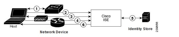
Extensible Authentication Protocol-Message Digest 5
Extensible Authentication Protocol-Message Digest 5 (EAP-MD5) provides one-way client authentication. The server sends the client a random challenge. The client proves its identity in a response by encrypting the challenge and its password with MD5. Because a man in the middle could see the challenge and response, EAP-MD5 is vulnerable to dictionary attack when used over an open medium. Because no server authentication occurs, it is also vulnerable to spoofing. Cisco ISE supports EAP-MD5 authentication against the Cisco ISE internal identity store. Host Lookup is also supported when using the EAP-MD5 protocol.
Lightweight Extensible Authentication Protocol
Cisco ISE currently uses Lightweight Extensible Authentication Protocol (LEAP) only for Cisco Aironet wireless networking. If you do not enable this option, Cisco Aironet end-user clients who are configured to perform LEAP authentication cannot access the network. If all Cisco Aironet end-user clients use a different authentication protocol, such as Extensible Authentication Protocol-Transport Layer Security (EAP-TLS), we recommend that you disable this option.
Note |
If users access your network by using a AAA client that is defined in the Network Devices section as a RADIUS (Cisco Aironet) device, then you must enable LEAP, EAP-TLS, or both; otherwise, Cisco Aironet users cannot authenticate. |
Protected Extensible Authentication Protocol
Protected Extensible Authentication Protocol (PEAP) provides mutual authentication, ensures confidentiality and integrity to vulnerable user credentials, protects itself against passive (eavesdropping) and active (man-in-the-middle) attacks, and securely generates cryptographic keying material. PEAP is compatible with the IEEE 802.1X standard and RADIUS protocol. Cisco ISE supports PEAP version 0 (PEAPv0) and PEAP version 1 (PEAPv1) with Extensible Authentication Protocol-Microsoft Challenge Handshake Authentication Protocol (EAP-MS-CHAP), Extensible Authentication Protocol-Generic Token Card (EAP-GTC), and EAP-TLS inner methods. The Cisco Secure Services Client (SSC) supplicant supports all of the PEAPv1 inner methods that Cisco ISE supports.
Advantages of Using PEAP
Supported Supplicants for the PEAP Protocol
-
Microsoft Built-In Clients 802.1X XP
- Microsoft Built-In Clients 802.1X Vista
- Cisco Secure Services Client (SSC), Release 4.0
- Cisco SSC, Release 5.1
- Funk Odyssey Access Client, Release 4.72
- Intel, Release 12.4.0.0
PEAP Protocol Flow
-
Cisco ISE and the peer build a TLS tunnel. Cisco ISE presents its certificate, but the peer does not. The peer and Cisco ISE create a key to encrypt the data inside the tunnel.
-
The inner method determines the flow within the tunnel:
-
EAP-MS-CHAPv2 inner method—EAP-MS-CHAPv2 packets travel inside the tunnel without their headers. The first byte of the header contains the type field. EAP-MS-CHAPv2 inner methods support the change-password feature. You can configure the number of times that the user can attempt to change the password through the Admin portal. User authentication attempts are limited by this number.
-
EAP-GTC inner method—Both PEAPv0 and PEAPv1 support the EAP-GTC inner method. The supported supplicants do not support PEAPv0 with the EAP-GTC inner method. EAP-GTC supports the change-password feature. You can configure the number of times that the user can attempt to change the password through the Admin portal. User authentication attempts are limited by this number.
-
EAP-TLS inner method—The Windows built-in supplicant does not support fragmentation of messages after the tunnel is established, and this affects the EAP-TLS inner method. Cisco ISE does not support fragmentation of the outer PEAP message after the tunnel is established. During tunnel establishment, fragmentation works as specified in PEAP documentation. In PEAPv0, EAP-TLS packet headers are removed, and in PEAPv1, EAP-TLS packets are transmitted unchanged.
-
Extensible Authentication Protocol-type, length, value (EAP-TLV) extension—EAP-TLV packets are transmitted unchanged. EAP-TLV packets travel with their headers inside the tunnel.
-
-
There is protected acknowledgment of success and failure if the conversation has reached the inner method.
The client EAP message is always carried in the RADIUS Access-Request message, and the server EAP message is always carried in the RADIUS Access-Challenge message. The EAP-Success message is always carried in the RADIUS Access-Accept message. The EAP-Failure message is always carried in the RADIUS Access-Reject message. Dropping the client PEAP message results in dropping the RADIUS client message.
Note |
Cisco ISE requires acknowledgment of the EAP-Success or EAP-Failure message during PEAPv1 communication. The peer must send back a PEAP packet with empty TLS data field to acknowledge the receipt of success or failure message. |
Extensible Authentication Protocol-Flexible Authentication via Secure Tunneling
Extensible Authentication Protocol-Flexible Authentication via Secure Tunneling (EAP-FAST) is an authentication protocol that provides mutual authentication and uses a shared secret to establish a tunnel. The tunnel is used to protect weak authentication methods that are based on passwords. The shared secret, referred to as a Protected Access Credentials (PAC) key, is used to mutually authenticate the client and server while securing the tunnel.
Benefits of EAP-FAST
- Mutual authentication—The EAP server must be able to verify the identity and authenticity of the peer, and the peer must be able to verify the authenticity of the EAP server.
- Immunity to passive dictionary attacks—Many authentication protocols require a password to be explicitly provided, either as cleartext or hashed, by the peer to the EAP server.
- Immunity to man-in-the-middle attacks—In establishing a mutually authenticated protected tunnel, the protocol must prevent adversaries from successfully interjecting information into the conversation between the peer and the EAP server.
- Flexibility to enable support for many different password authentication interfaces such as MS-CHAPv2, Generic Token Card (GTC), and others—EAP-FAST is an extensible framework that allows support of multiple internal protocols by the same server.
- Efficiency—When using wireless media, peers are limited in computational and power resources. EAP-FAST enables the network access communication to be computationally lightweight.
- Minimization of the per-user authentication state requirements of the authentication server—With large deployments, it is typical to have many servers acting as the authentication servers for many peers. It is also highly desirable for a peer to use the same shared secret to secure a tunnel much the same way that it uses the username and password to gain access to the network. EAP-FAST facilitates the use of a single, strong, shared secret by the peer, while enabling servers to minimize the per-user and device state that it must cache and manage.
EAP-FAST Flow
- Provisioning phase—This is phase zero of EAP-FAST. During this phase, the peer is provisioned with a unique, strong secret that is referred to as the PAC that is shared between the Cisco ISE and the peer.
- Tunnel establishment phase—The client and server authenticate each other by using the PAC to establish a fresh tunnel key. The tunnel key is then used to protect the rest of the conversation and provides message confidentiality and with authenticity.
- Authentication phase—The authentication is processed inside the tunnel and includes the generation of session keys and protected termination.Cisco ISE supports EAP-FAST versions 1 and 1a.
Enable MAB from Non-Cisco Devices
Configure the following settings sequentially to configure MAB from non-Cisco devices.
Procedure
| Step 1 |
Ensure that the MAC address of the endpoints that are to be authenticated are available in the Endpoints database. You can add these endpoints or have them profiled automatically by the Profiler service. |
| Step 2 |
Create a Network Device Profile based on the type of MAC authentication used by the non-Cisco device (PAP, CHAP, or EAP-MD5). |
| Step 3 |
Choose Administration > Network Resources > Network Devices. |
| Step 4 |
Select the device for which you want to enable MAB, and then click Edit. |
| Step 5 |
In the Network Device page, select the network device profile that you created in step 2 from the Device Profile drop-down list. |
| Step 6 |
Click Save. |
Note |
For Cisco NADs, the Service-Type values used for MAB and web/user authentication are different. This allows ISE to differentiate MAB from web authentication when Cisco NADs are used. Some non-Cisco NADs use the same value for the Service-Type attribute for both MAB and web/user authentication; this may lead to security issues in your access policies. If you are using MAB with non-Cisco devices, we recommend that you configure additional authorization policy rules to ensure that your network security is not compromised. For example, if a printer is using MAB, you could configure an authorization policy rule to restrict it to printer protocol ports in the ACL. |
Enable MAB from Cisco Devices
Configure the following settings sequentially to configure MAB from Cisco devices.
Procedure
| Step 1 |
Ensure that the MAC address of the endpoints that are to be authenticated are available in the Endpoints database. You can add these endpoints or have them profiled automatically by the Profiler service. |
| Step 2 |
Create a Network Device Profile based on the type of MAC authentication used by the Cisco device (PAP, CHAP, or EAP-MD5). |
| Step 3 |
Choose Administration > Network Resources > Network Devices. |
| Step 4 |
Select the device for which you want to enable MAB, and then click Edit. |
| Step 5 |
In the Network Device page, select the network device profile that you created in step 2 from the Device Profile drop-down list. |
| Step 6 |
Click Save. |
|
For information about IP phone authentication capabilities, see Phone Authentication Capabilities. |
TrustSec Architecture
The Cisco TrustSec solution establishes clouds of trusted network devices to build secure networks. Each device in the Cisco TrustSec cloud is authenticated by its neighbors (peers). Communication between the devices in the TrustSec cloud is secured with a combination of encryption, message integrity checks, and data-path replay protection mechanisms. The TrustSec solution uses the device and user identity information that it obtains during authentication to classify, or color, the packets as they enter the network. This packet classification is maintained by tagging packets when they enter the TrustSec network so that they can be properly identified for the purpose of applying security and other policy criteria along the data path. The tag, also called the security group tag (SGT), allows Cisco ISE to enforce access control policies by enabling the endpoint device to act upon the SGT to filter traffic.
The following figure shows an example of a TrustSec network cloud.
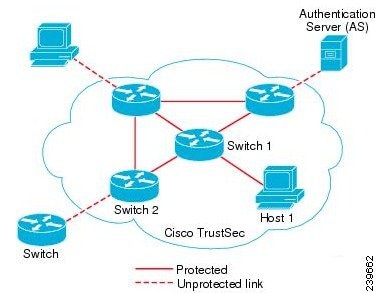
|
For information on how to simplify network segmentation and improve security using Cisco TrustSec, see Simplify Network Segmentation with Cisco TrustSec and Policy-Based Software Defined Segmentation and Cisco TrustSec Improve Security White Paper. For a complete list of Cisco TrustSec platform support matrices, see Cisco TrustSec Platform Support Matrix. For a complete list of support documentation available for TrustSec, see Cisco TrustSec. For a complete list of TrustSec community resources, see TrustSec Community. |
TrustSec Components
The key TrustSec components include:
-
Network Device Admission Control (NDAC)—In a trusted network, during authentication, each network device (for example Ethernet switch) in a TrustSec cloud is verified for its credential and trustworthiness by its peer device. NDAC uses the IEEE 802.1X port-based authentication and uses Extensible Authentication Protocol-Flexible Authentication via Secure Tunneling (EAP-FAST) as its Extensible Authentication Protocol (EAP) method. Successful authentication and authorization in the NDAC process results in Security Association Protocol negotiation for IEEE 802.1AE encryption.
-
Endpoint Admission Control (EAC)—An authentication process for an endpoint user or a device connecting to the TrustSec cloud. EAC typically happens at the access level switch. Successful authentication and authorization in EAC process results in SGT assignment to the user or device. EAC access methods for authentication and authorization includes:
-
802.1X port-based authentication
-
MAC authentication bypass (MAB)
-
Web authentication (WebAuth)
-
-
Security Group (SG)—A grouping of users, endpoint devices, and resources that share access control policies. SGs are defined by the administrator in Cisco ISE. As new users and devices are added to the TrustSec domain, Cisco ISE assigns these new entities to the appropriate security groups.
-
Security Group Tag (SGT)—TrustSec service assigns to each security group a unique 16-bit security group number whose scope is global within a TrustSec domain. The number of security groups in the switch is limited to the number of authenticated network entities. You do not have to manually configure security group numbers. They are automatically generated, but you have the option to reserve a range of SGTs for IP-to-SGT mapping.
-
Security Group Access Control List (SGACL)—SGACLs allow you to control the access and permissions based on the SGTs that are assigned. The grouping of permissions into a role simplifies the management of security policy. As you add devices, you simply assign one or more security groups, and they immediately receive the appropriate permissions. You can modify the security groups to introduce new privileges or restrict current permissions.
-
Security Exchange Protocol (SXP)—SGT Exchange Protocol (SXP) is a protocol developed for TrustSec service to propagate the IP-SGT bindings across network devices that do not have SGT-capable hardware support to hardware that supports SGT/SGACL.
-
Environment Data Download—The TrustSec device obtains its environment data from Cisco ISE when it first joins a trusted network. You can also manually configure some of the data on the device. The device must refresh the environment data before it expires. The TrustSec device obtains the following environment data from Cisco ISE:
-
Server lists—List of servers that the client can use for future RADIUS requests (for both authentication and authorization)
-
Device SG—Security group to which the device itself belongs
-
Expiry timeout—Interval that controls how often the TrustSec device should download or refresh its environment data
-
-
Identity-to-Port Mapping—A method for a switch to define the identity on a port to which an endpoint is connected, and to use this identity to look up a particular SGT value in the Cisco ISE server.
TrustSec Terminology
The following table lists some of the common terms that are used in the TrustSec solution and their meaning in an TrustSec environment.
|
Term |
Meaning |
|---|---|
|
Supplicant |
A device that tries to join a trusted network. |
|
Authentication |
The process of verifying the identity of each device before allowing it to be part of the trusted network. |
|
Authorization |
The process of deciding the level of access to a device that requests access to a resource on a trusted network based on the authenticated identity of the device. |
|
Access control |
The process of applying access control on a per-packet basis based on the SGT that is assigned to each packet. |
|
Secure communication |
The process of encryption, integrity, and data-path replay protection for securing the packets that flow over each link in a trusted network. |
|
TrustSec device |
Any of the Cisco Catalyst 6000 Series or Cisco Nexus 7000 Series switches that support the TrustSec solution. |
|
TrustSec-capable device |
A TrustSec-capable device will have TrustSec-capable hardware and software. For example, the Nexus 7000 Series Switches with the Nexus operating system. |
|
TrustSec seed device |
The TrustSec device that authenticates directly against the Cisco ISE server. It acts as both the authenticator and supplicant. |
|
Ingress |
When packets first encounter a TrustSec-capable device that is part of a network where the Cisco TrustSec solution is enabled, they are tagged with an SGT. This point of entry into the trusted network is called the ingress. |
|
Egress |
When packets pass the last TrustSec-capable device that is part of a network where the Cisco TrustSec solution is enabled, they are untagged. This point of exit from the trusted network is called the egress. |
Supported Switches and Required Components for TrustSec
To set up a Cisco ISE network that is enabled with the Cisco TrustSec solution, you need switches that support the TrustSec solution and other components. Apart from the switches, you also need other components for identity-based user access control using the IEEE 802.1X protocol. For a complete up-to-date list of the Trustsec-supported Cisco switch platforms and the required components, see Cisco TrustSec-Enabled Infrastructure.
Integration with Cisco DNA Center
Cisco ISE is a major component of Cisco’s Digital Network Architecture (DNA). Cisco DNA Center allows you to automate your network to provide business agility. Cisco ISE provides Cisco DNA with policy components that segment your network to help mitigate security threats and vulnerabilities. When Cisco ISE and Cisco DNA Center are integrated, Cisco ISE provides groups and policies to Cisco DNA Center. Cisco DNA Center uses these policies to enforce controlled access to the network.
Connecting Cisco DNA Center to Cisco ISE
See the requirements and instructions for configuring Cisco DNA Center and Cisco ISE in the DNAC User Guide https://www.cisco.com/c/en/us/support/cloud-systems-management/dna-center/products-user-guide-list.html.
This section provides additional information about the Cisco ISE configuration for Cisco DNA Center.
-
Passwords: Cisco DNA Center uses the Cisco ISE CLI password when it connects to Cisco ISE to run CLI commands. The CLI and the Admin usernames and passwords must be the same. For details about system passwords, see the Administrative Access to Cisco ISE section in Cisco ISE Admin Guide: Getting Started .
-
APIs: Cisco DNA Center configures some parts of ISE by calling ISE APIs. You must enable API access in Cisco ISE, but do not enable CSRF. For more information, see the Enable External RESTful Services APIs section in
-
pxGrid: Cisco ISE is a pxGrid controller, and Cisco DNA Center is a subscriber. Both Cisco ISE and Cisco DNA Center monitor the Trustsec (SD-Access) content, which contains SGT and SGACL information. You must synchronize the system clocks between Cisco ISE and Cisco DNA Center. Cisco ISE uses a certificate to connect to pxGrid, which is configured by Cisco DNA Center for their connection. For more information about pxGrid in Cisco ISE, see the pxGrid Node section in Cisco ISE Admin Guide: Deployment .
-
Cisco ISE IP Address: The connection between the Cisco ISE PAN and Cisco DNA Center must be direct. It cannot be through a proxy, a load balancer, or virtual IP address. Both Cisco ISE and Cisco DNA Center configure a static address for each other.
Verify that Cisco ISE is not using a proxy. If it is, exclude the Cisco DNA Center IP from the proxy.
-
SXP: SXP is not required to communicate with Cisco DNA Center. You may want to enable SXP when you connect Cisco ISE to the DNA-managed network, so Cisco ISE can communicate with network devices that don’t have hardware support for Trustsec (SD-Access).
-
Certificate for connections to Cisco ISE:
-
The Cisco ISE admin certificate must contain the Cisco ISE IP or FQDN in subject name or SAN.
-
ECDSA keys are not supported for SSH keys, ISE SSH access, or in certificates for the Cisco DNA Center and Cisco ISE connection.
-
Self-signed certs on Cisco DNA Center must have the Basic Constraint's extension with cA:TRUE (RFC5280 section-4.2.19).
-
TrustSec Dashboard
The TrustSec dashboard is a centralized monitoring tool for the TrustSec network.
The TrustSec dashboard contains the following dashlets:
-
Metrics: The Metrics dashlet displays statistics about the behavior of the TrustSec network.
-
Active SGT Sessions: The Active SGT Sessions dashlet displays the SGT sessions that are currently active in the network. The Alarms dashlet displays alarms that are related to the TrustSec sessions.
-
Alarms
-
NAD / SGT Quick View: The Quick View dashlet displays TrustSec-related information for NADs and SGTs.
-
TrustSec Sessions / NAD Activity Live Log: In the Live Log dashlet, click the TrustSec Sessions link to view the active TrustSec sessions. You can also view information about TrustSec protocol data requests and responses from NADs to Cisco ISE.
Metrics
This section displays statistics about the behavior of the TrustSec network. You can select the time frame (for example, past 2 hours, past 2 days, and so on) and the chart type (for example, bars, line, spline).
The latest bar values are displayed on the graphs. It also displays the percentage change from the previous bar. If there is an increase in the bar value, it will be displayed in green with a plus sign. If there is a decrease in the value, it will be displayed in red with a minus sign.
Place your cursor on a bar of a graph to view the time at which the value was calculated and its exact value in the following format: <Value:xxxx Date/Time: xxx>
You can view the following metrics:
|
SGT sessions |
Displays the total number of SGT sessions created during the chosen time frame.
|
||
|
SGTs in use |
Displays the total number of unique SGTs that were used during the chosen time frame. For example, in one hour, if there were 200 TrustSec sessions, but ISE responded with only 6 types of SGTs in the authorization responses, the graph will display a value 6 for this hour. |
||
|
Alarms |
Displays the total number of alarms and errors that occurred during the chosen time frame. Errors are displayed in red and alarms are displayed in yellow. |
||
|
NADs in use |
Displays the number of unique NADs, which took part in TrustSec authentications during the chosen time frame. |
Current Network Status
The middle section of the dashboard displays information about the current status of the TrustSec network. The values displayed in the graphs are updated when the page is loaded and can be refreshed by using the Refresh Dashboard option.
Active SGT Sessions
This dashlet displays the SGT sessions that are currently active in the network. You can view the top 10 most used or least used SGTs. The X-axis shows the SGT usage and the Y-axis displays the names of the SGTs.
To view the TrustSec session details for an SGT, click on the bar corresponding to that SGT. The details of the TrustSec sessions related to that SGT are displayed in the Live Log dashlet.
Alarms
This dashlet displays the alarms related to the TrustSec sessions. You can view the following details:
-
Alarm Severity—Displays an icon that represents the severity level of the alarm.
- High—Includes the alarms that indicate failure in the TrustSec network (for example, device failed to refresh its PAC). Marked with red icon.
-
Medium—Includes warnings that indicate wrong configuration of the network device (for example, device failed to accept CoA message). Marked with yellow.
-
Low—Includes general information and update on network behavior (for example, configuration changes in TrustSec). Marked with blue.
-
Alarm description
-
Number of times the alarm occurred since this alarm counter was last reset.
-
Alarm last occurrence time
Quick View
The Quick View dashlet displays TrustSec-related information for NADs. You can also view the TrustSec-related information for an SGT.
NAD Quick View
Enter the name of the TrustSec network device for which you want to view the details in the Search box and press Enter. The search box provides an auto-complete feature, which filters and shows the matched device names in a drop down as the user types into the text box.
The following details are displayed:
-
NDGs—Lists the Network Device Groups (NDGs) to which this network device belongs.
-
IP Address—IP address of the network device. Click on this link to view the NAD activity details in the Live Logs dashlet.
-
Active sessions—Number of active TrustSec sessions connected to this device.
-
PAC expiry—PAC expiry date.
-
Last Policy Refresh—Policy last download date.
-
Last Authentication—Last authentication report timestamp for this device.
-
Active SGTs—Lists the SGTs used in the active sessions that are related to this network device. The number displayed within the brackets denotes the number of sessions that are currently using this SGT. Click on an SGT link to view the TrustSec session details in the Live Log dashlet.
You can use the Show Latest Logs option to view the NAD activity live logs for the device.
SGT Quick View
Enter the name of the SGT for which you want to view the details in the Search box and press Enter.
The following information will be displayed in this dashlet:
-
Value—SGT value (both decimal and hexadecimal).
-
Icon—Displays the icon that is assigned to this SGT.
-
Active sessions—Number of active sessions that are currently using this SGT.
-
Unique users—Number of unique usernames, which hold this SGT in their active sessions.
-
Updated NADs—Number of NADs which downloaded policies for this SGT.
Live Log
Click the TrustSec Sessions link to view the active TrustSec sessions (sessions that have SGT as part of their response).
Click the NAD Activity link to view information regarding TrustSec protocol data requests and responses from NADs to Cisco ISE.
Configure TrustSec Global Settings
For Cisco ISE to function as an TrustSec server and provide TrustSec services, you must define some global TrustSec settings.
Before you begin
-
Before you configure global TrustSec settings, ensure that you have defined global EAP-FAST settings (choose ).
You may change the Authority Identity Info Description to your Cisco ISE server name. This description is a user-friendly string that describes the Cisco ISE server that sends credentials to an endpoint client. The client in a Cisco TrustSec architecture can be either the endpoint running EAP-FAST as its EAP method for IEEE 802.1X authentication or the supplicant network device performing Network Device Access Control (NDAC). The client can discover this string in the protected access credentials (PAC) type-length-value (TLV) information. The default value is Identity Services Engine. You should change the value so that the Cisco ISE PAC information can be uniquely identified on network devices upon NDAC authentication.
-
To perform the following task, you must be a Super Admin or System Admin.
Procedure
| Step 1 |
Choose Work Centers > TrustSec > Settings > General TrustSec Settings. |
| Step 2 |
Enter the values in the fields. |
| Step 3 |
Click Save. |
What to do next
General TrustSec Settings
| Fields | Usage Guidelines | ||
|---|---|---|---|
| Verify TrustSec Deployment |
This option helps you to verify whether the latest TrustSec policies are deployed on all network devices. Alarms are displayed in the Alarms dashlet (under Work Centers > TrustSec > Dashboard and Home > Summary) if there are any discrepancies between the policies configured on Cisco ISE and the network device. The following alarms are displayed in the TrustSec dashboard:
The Verify Deployment option is also available in the following windows:
Automatic Verification After Every Deploy—Check this check box if you want Cisco ISE to verify the updates on all the network devices after every deployment. When the deployment process is complete, the verification process is started after the time you specify in the Time after Deploy Process field. Time After Deploy Process—Specify the time for which you want Cisco ISE to wait for after the deployment process is complete, before starting the verification process. The valid range is from 10 - 60 minutes. The current verification process is cancelled if a new deployment request is received during the waiting period or when the verification is in progress. Verify Now—Click this option to start the verification process immediately. |
||
|
Tunnel PAC Time to Live |
Specify the expiry time for the PAC. The tunnel PAC generates a tunnel for the EAP-FAST protocol. You can specify the time
in seconds, minutes, hours, days, or weeks. The default value is 90 days. The following are the valid ranges:
|
||
|
Proactive PAC Update Will Occur After |
Cisco ISE proactively provides a new PAC to a client after successful authentication when a configured percentage of the Tunnel PAC TTL remains. The server initiates the tunnel PAC update if the first successful authentication occurs before the PAC expires. This mechanism allows the client to be updated with a valid PAC. The default value is 10%. |
||
|
System will Assign SGT Numbers |
Choose this option if you want all the SGT numbers to be automatically generated by Cisco ISE. |
||
|
Except Numbers in Range |
Choose this option if you want to reserve a range of SGT numbers to be configured on the device manually. Cisco ISE will not use the values in this range while generating the SGTs. |
||
|
User Must Enter SGT Numbers Manually |
Choose this option to define the SGT numbers manually. |
||
|
Security Group Tag Numbering for APIC EPGs |
Check this check box and specify the range of numbers to be used for the SGTs created based on the EPGs learnt from APIC. |
||
|
Auto Create Security Groups When Creating Authorization Rules |
Check this check box to create the SGTs automatically while creating the authorization policy rules. When this option is selected, the following message is displayed at the top of the Authorization Policy window: The auto-created SGTs are named based on the rule attributes.
By default, this option is disabled after a fresh install or upgrade. |
||
|
SGT Number Range For Auto-Creation |
Check this check box and specify the range of numbers to be used for the auto-created SGTs. When the range of numbers allocated for the auto-created SGTs are used up, Cisco ISE will extend the range by 50 and notify users about this change. |
||
|
Automatic Naming Options |
Use this option to define the naming convention for the auto-created SGTs. (Mandatory) Name Will Include—Choose one of the following options:
By default, the Rule name option is selected. Optionally, you can add the following information to the SGT name:
Cisco ISE will display a sample SGT name in the Example Name field based on your selections. If an SGT already exists with the same name, ISE will append _x to the SGT name, where x is the first value, starting at 1 (which is not in use in the current name). If the new name is longer than 32 characters, Cisco ISE will truncate it to the first 32 characters. |
||
|
IP SGT Static Mapping of Hostnames |
If FQDN and hostnames are used, Cisco ISE looks for the corresponding IP addresses in the PAN and PSN nodes while deploying
the mappings and checking the deployment status. You can use this option to specify the number of mappings created for the
IP addresses returned by the DNS query. You can select one of the following options:
|
Configure TrustSec Matrix Settings
Before you begin
To perform the following task, you must be a Super Admin or System Admin.
Procedure
| Step 1 |
Choose Work Centers > TrustSec > Settings > TrustSec Matrix Settings. |
| Step 2 |
Enter the required details in the TrustSec Matrix Settings page. |
| Step 3 |
Click Save. |
TrustSec Matrix Settings
The following table describes the fields on the TrustSec Matrix Settings page. The navigation path for this page is: Work Centers > TrustSec > Settings > TrustSec Matrix Settings.
|
Fields |
Usage Guidelines |
||
|---|---|---|---|
|
Allow Multiple SGACLs |
Check this check box if you want to allow multiple SGACLs in a cell. If this option is not selected, Cisco ISE will allow only one SGACL per cell. By default, this option is disabled upon fresh install. After upgrade, Cisco ISE will scan the Egress cells and if it identifies at least one cell with multiple SGACLs assigned to it, it allows the admin to add multiple SGACLs in a cell. Otherwise, it allows only one SGACL per cell.
|
||
|
Allow Monitoring |
Check this check box to enable monitoring for all cells in the matrix. If monitoring is disabled, Monitor All icon is greyed out and the Monitor option is disabled in the Edit Cell dialog. By default, monitoring is disabled upon fresh install.
|
||
|
Show SGT Numbers |
Use this option to display or hide the SGT values (both decimal and hexadecimal) in the matrix cells. By default, the SGT values are displayed in the cells. |
||
|
Appearance Settings |
The following options are available:
|
||
|
Color/Pattern |
To make the matrix more readable, you can apply coloring and patterns to the matrix cells based on the cell contents. The following display types are available:
|
Configure TrustSec Devices
For Cisco ISE to process requests from TrustSec-enabled devices, you must define these TrustSec-enabled devices in Cisco ISE.
Procedure
| Step 1 |
Choose Work Centers > TrustSec > Components > Network Devices. |
| Step 2 |
Click Add. |
| Step 3 |
Enter the required information in the Network Devices section. |
| Step 4 |
Check the Advanced Trustsec Settings check box to configure a Trustsec-enabled device. |
| Step 5 |
Click Submit. |
OOB TrustSec PAC
All TrustSec network devices possess a TrustSec PAC as part of the EAP-FAST protocol. This is also utilized by the secure RADIUS protocol where the RADIUS shared secret is derived from parameters carried by the PAC. One of these parameters, Initiator-ID, holds the TrustSec network device identity, namely the Device ID.
If a device is identified using TrustSec PAC and there is no match between the Device ID, as configured for that device on Cisco ISE, and the Initiator-ID on the PAC, the authentication fails.
Some TrustSec devices (for example, Cisco firewall ASA) do not support the EAP-FAST protocol. Therefore, Cisco ISE cannot provision these devices with TrustSec PAC over EAP-FAST. Instead, the TrustSec PAC is generated on Cisco ISE and manually copied to the device; hence this is called as the Out of Band (OOB) TrustSec PAC generation.
When you generate a PAC from Cisco ISE, a PAC file encrypted with the Encryption Key is generated.
This section describes the following:
Generate a TrustSec PAC from the Settings Screen
You can generate a TrustSec PAC from the Settings screen.
Procedure
| Step 1 |
Choose . |
| Step 2 |
From the Settings navigation pane on the left, click Protocols. |
| Step 3 |
Choose . |
| Step 4 |
Generate TrustSec PAC. |
Generate a TrustSec PAC from the Network Devices Screen
You can generate a TrustSec PAC from the Network Devices screen.
Procedure
| Step 1 |
Choose Work Centers > TrustSec > Components > Network Devices. |
| Step 2 |
Click Add. You can also click Add new device from the action icon on the Network Devices navigation pane. |
| Step 3 |
If you are adding a new device, provide a device name. |
| Step 4 |
Check the Advanced TrustSec Settings check box to configure a TrustSec device. |
| Step 5 |
Under the Out of Band (OOB) TrustSec PAC sub section, click Generate PAC. |
| Step 6 |
Provide the following details:
|
| Step 7 |
Click Generate PAC. |
Generate a TrustSec PAC from the Network Devices List Screen
You can generate a TrustSec PAC from the Network Devices list screen.
Procedure
| Step 1 |
Choose Work Centers > TrustSec > Components > Network Devices. |
| Step 2 |
Click Network Devices. |
| Step 3 |
Check the check box next to a device for which you want to generate the TrustSec PAC and click Generate PAC. |
| Step 4 |
Provide the details in the fields. |
| Step 5 |
Click Generate PAC. |
Push Button
The Push option in the egress policy initiates a CoA notification that calls the Trustsec devices to immediately request for updates from Cisco ISE regarding the configuration changes in the egress policy.
Configure TrustSec AAA Servers
You can configure a list of Cisco ISE servers in your deployment in the AAA server list to allow TrustSec devices to be authenticated against any of these servers. When you add Cisco ISE servers to this list, all these server details are downloaded to the TrustSec device. When a TrustSec device tries to authenticate, it chooses any Cisco ISE server from this list and, if the first server is down or busy, the TrustSec device can authenticate itself against any of the other servers from this list. By default, the primary Cisco ISE server is a TrustSec AAA server. We recommend that you configure additional Cisco ISE servers in this AAA server list so that if one server is busy, another server from this list can handle the TrustSec request.
This page lists the Cisco ISE servers in your deployment that you have configured as your TrustSec AAA servers.
You can click the Push button to initiate an environment CoA notification after you configure multiple TrustSec AAA servers. This environment CoA notification goes to all TrustSec network devices and provides an update of all TrustSec AAA servers that were changed.
Before you begin
To perform the following task, you must be a Super Admin or System Admin.
Procedure
| Step 1 |
Choose Work Centers > TrustSec > Components > TrustSec AAA Servers. |
| Step 2 |
Click Add. |
| Step 3 |
Enter the values as described:
|
| Step 4 |
Click Submit. |
What to do next
Configure Security Groups.
Security Groups Configuration
A Security Group (SG) or Security Group Tag (SGT) is an element that is used in TrustSec policy configuration. SGTs are attached to packets when they move within a trusted network. These packets are tagged when they enter a trusted network (ingress) and untagged when they leave the trusted network (egress).
SGTs are generated in a sequential manner, but you have the option to reserve a range of SGTs for IP to SGT mapping. Cisco ISE skips the reserved numbers while generating SGTs.
TrustSec service uses these SGTs to enforce the TrustSec policy at egress.
You can configure security groups from the following pages in the Admin portal:
-
Work Centers > TrustSec > Components > Security Groups.
-
Directly from egress policy page at .
You can click the Push button to initiate an environment CoA notification after updating multiple SGTs. This environment CoA notification goes to all TrustSec network devices forcing them to start a policy/data refresh request.
Add Security Groups
Each security group in your TrustSec solution should be assigned a unique SGT. Even though Cisco ISE supports 65,535 SGTs, having fewer number of SGTs would enable you to deploy and manage the TrustSec solution easily. We recommend a maximum of 4,000 SGTs.
Before you begin
To perform the following task, you must be a Super Admin or System Admin.
Procedure
| Step 1 |
Choose Work Centers > TrustSec > Components > Security Groups. |
| Step 2 |
Click Add to add a new security group. |
| Step 3 |
Enter a name and description (optional) for the new security group. |
| Step 4 |
Check the Propagate to ACI check box if you want to propagate this SGT to ACI. The SXP mappings that are related to this SGT will be propagated to ACI only if they belong to a VPN that is selected in the ACI Settings page. This option is disabled by default. |
| Step 5 |
Enter a Tag Value. Tag value can be set to be entered manually or autogenerate. You can also reserve a range for the SGT. You can configure it from the General TrustSec Settings page (Work Centers > TrustSec > Settings > General TrustSec Settings). |
| Step 6 |
Click Save. |
What to do next
Configure Security Group Access Control Lists
Import Security Groups into Cisco ISE
You can import security groups in to a Cisco ISE node using a comma-separated value (CSV) file. You must first update the template before you can import security groups into Cisco ISE. You cannot run import of the same resource type at the same time. For example, you cannot concurrently import security groups from two different import files.
You can download the CSV template from the Admin portal, enter your security group details in the template, and save the template as a CSV file, which you can then import back into Cisco ISE.
While importing security groups, you can stop the import process when Cisco ISE encounters the first error.
Procedure
| Step 1 |
Choose Work Centers > TrustSec > Components > Security Groups. |
| Step 2 |
Click Import. |
| Step 3 |
Click Browse to choose the CSV file from the system that is running the client browser. |
| Step 4 |
Check the Stop Import on First Error check box. |
| Step 5 |
Click Import . |
Export Security Groups from Cisco ISE
You can export security groups configured in Cisco ISE in the form of a CSV file that you can use to import these security groups into another Cisco ISE node.
Procedure
| Step 1 |
Choose Work Centers > TrustSec > Components > Security Groups. |
| Step 2 |
Click Export. |
| Step 3 |
To export security groups, you can do one of the following:
|
| Step 4 |
Save the export.csv file to your local hard disk. |
Add IP SGT Static Mapping
You can use the IP-SGT static mappings to deploy the mappings on TrustSec devices and SXP domains in a unified manner. While creating a new IP-SGT static mapping, you can specify the SXP domains and the devices on which you want to deploy this mapping. You can also associate the IP-SGT mapping to a mapping group.
Procedure
| Step 1 |
Choose Work Centers > TrustSec > Components > IP SGT Static Mapping. |
| Step 2 |
Click Add. |
| Step 3 |
Enter the hostname or the IP address. |
| Step 4 |
If you want to use an existing mapping group, click Add to a Mapping Group and select the required group from the Mapping Group drop-down list. If you want to
map this IP address/hostname to an SGT individually, click
Map to SGT
Individually and do the following:
|
| Step 5 |
Click Save. |
Deploy IP SGT Static Mappings
After adding the mappings, deploy the mappings on the target network devices using the Deploy option. You must do this explicitly even if you have saved the mappings earlier. Click Check Status to check the deployment status of the devices.
Procedure
| Step 1 |
From the Work Centers tab, choose TrustSec > Components > IP SGT Static Mapping. |
| Step 2 |
Check the check boxes near the mappings that you want to deploy. Check the check box at the top if you want to deploy all the mappings. |
| Step 3 |
Click Deploy. All the TrustSec devices are listed in the Deploy IP SGT Static Mapping window. |
| Step 4 |
Check the check boxes near the devices or the device groups to which the selected mappings must be deployed. Check the check box at the top if you want to select all the devices. Use the filter option to search for specific devices. If you do not select any device, the selected mappings are deployed on all the TrustSec devices. |
| Step 5 |
Click Apply. The Deployment Status window shows the order in which the devices are updated and the devices that are not getting updated because of an error or because the device is unreachable. After the deployment is complete, the window displays the total number of devices that are successfully updated and the number of devices that are not updated. |
Use the Check Status option in the IP SGT Static Mapping page to check if different SGTs are assigned to the same IP address for a specific device. You can use this option to locate the devices that have conflicting mappings, IP addresses that are mapped to multiple SGTs, and the SGTs that are assigned to the same IP address. The Check Status option can be used even if device groups, FQDN, hostname, or IPv6 addresses are used in the deployment. You must remove the conflicting mappings or modify the scope of deployment before deploying these mappings.
IPv6 addresses can be used in IP SGT static mappings. These mappings can be propagated using SSH or SXP to specific network devices or network device groups.
If FQDN and hostnames are used, Cisco ISE looks for the corresponding IP addresses in the PAN and PSN nodes while deploying the mappings and checking the deployment status.
-
Create mappings for all the IP addresses returned by a DNS query.
-
Create mappings only for the first IPv4 address and the first IPv6 address returned by a DNS query.
Import IP SGT Static Mappings into Cisco ISE
You can import IP SGT mappings using a CSV file.
You can also download the CSV template from the Admin portal, enter your mapping details, save the template as a CSV file, and then import it back into Cisco ISE.
Procedure
| Step 1 |
Choose Work Centers > TrustSec > Components > IP SGT Static Mapping. |
| Step 2 |
Click Import. |
| Step 3 |
Click Browse to select the CSV file from the system that is running the client browser. |
| Step 4 |
Click Upload. |
Export IP SGT Static Mappings from Cisco ISE
You can export the IP SGT mappings in the form of a CSV file. You can use this file to import these mappings into another Cisco ISE node.
Procedure
| Step 1 |
Choose Work Centers > TrustSec > Components > IP SGT Static Mapping. |
| Step 2 |
Do one of the following:
|
| Step 3 |
Save the mappings.csv file to your local hard disk. |
Add SGT Mapping Group
Before you begin
To perform the following task, you must be a Super Admin or System Admin.
Procedure
| Step 1 |
Choose Work Centers > TrustSec > Components > IP SGT Static Mapping > Manage Groups. |
| Step 2 |
Click Add. |
| Step 3 |
Enter a name and description for the mapping group. |
| Step 4 |
Do the following:
|
| Step 5 |
Click Save. |
You can also update or delete the mappings and mapping groups. To update a mapping or mapping group, check the check box next to the mapping or mapping group that you want to update, and then click Edit. To delete a mapping or mapping group, check the check box next to the mapping or mapping group that you want to delete, and then click Trash > Selected. When a mapping group is deleted, the IP SGT mappings within that group are also deleted.
Add Security Group Access Control Lists
Before you begin
To perform the following task, you must be a Super Admin or System Admin.
Procedure
| Step 1 |
Choose Work Centers > TrustSec > Components > Security Group ACLs. |
||||||||||||||
| Step 2 |
Click Add to create a new Security Group ACL. |
||||||||||||||
| Step 3 |
Enter the following information:
|
||||||||||||||
| Step 4 |
Click Submit. |
Note |
Cisco ISE has the following predefined SGACLs: Permit IP, Permit IP Log, Deny IP, and Deny IP Log. You can use these SGACLs to configure the TrustSec Matrix using the GUI or ERS API. Though these SGACLs are not listed in the Security Group ACLs listing page in the GUI, these SGACLs will be listed when you use the ERS API to list the available SGACLs (ERS getAll call). |
Egress Policy
The egress table lists the source and destination SGTs, both reserved and unreserved. This page also allows you to filter the egress table to view specific policies and also to save these preset filters. When the source SGT tries to reach the destination SGT, the TrustSec-capable device enforces the SGACLs based on the TrustSec policy as defined in the Egress Policy. Cisco ISE creates and provisions the policy.
After you create the SGTs and SGACLs, which are the basic building blocks required to create a TrustSec policy, you can establish a relationship between them by assigning SGACLs to source and destination SGTs.
Each combination of a source SGT to a destination SGT is a cell in the Egress Policy.
You can view the Egress Policy in the Work Centers > TrustSec > TrustSec Policy > Egress Policy page.
You can view the Egress policy in three different ways:
-
Source Tree View
-
Destination Tree View
-
Matrix View
Source Tree View
The Source Tree view lists a compact and organized view of source SGTs in a collapsed state. You can expand any source SGT to see the internal table that lists all information related to that selected source SGT. This view displays only the source SGTs that are mapped to destination SGTs. If you expand a specific source SGT, it lists all destination SGTs that are mapped to this source SGT and and the corresponding policy (SGACLs) in a table.
You will see three dots (...) next to some fields. This signifies that there is more information contained in the cell. You can position the cursor over the three dots to view the rest of the information in a quick view popup. When you position the cursor over an SGT name or an SGACL name, a quick view popup opens to display the content of that particular SGT or SGACL.
Destination Tree View
The Destination Tree view lists a compact and organized view of destination SGTs in a collapsed state. You can expand any destination SGTs to see the internal table that lists all information related to that selected destination SGT. This view displays only the destination SGTs that are mapped to source SGTs. If you expand a specific destination SGT, it lists all source SGTs that are mapped to this destination SGT and and the corresponding policy (SGACLs) in a table.
You will see three dots (...) next to some fields. This signifies that there is more information contained in the cell. You can position the cursor over the three dots to view the rest of the information in a quick view popup. When you position the cursor over an SGT name or an SGACL name, a quick view popup opens to display the content of that particular SGT or SGACL.
Matrix View
The Matrix View of the Egress policy looks like a spreadsheet. It contains two axis:
-
Source Axis—The vertical axis lists all the source SGTs.
-
Destination Axis—The horizontal axis lists all the destination SGTs.
The mapping of a source SGT to a destination SGT is represented as a cell. If a cell contains data, then it represents that there is a mapping between the corresponding source SGT and the destination SGT. There are two types of cells in the matrix view:
-
Mapped cells—When a source and destination pair of SGTs is related to a set of ordered SGACLs and has a specified status.
-
Unmapped cells—When a source and destination pair of SGTs is not related to any SGACLs and has no specified status.
The Egress Policy cell displays the source SGT, the destination SGT, and the Final Catch All Rule as a single list under SGACLs, separated by commas. The Final Catch All Rule is not displayed if it is set to None. An empty cell in a matrix represents an unmapped cell.
In the Egress Policy matrix view, you can scroll across the matrix to view the required set of cells. The browser does not load the entire matrix data at once. The browser requests the server for the data that falls in the area you are scrolling in. This prevents memory overflow and performance issues.
You can use the following options in the View drop-down list to change the matrix view.
-
Condensed with SGACL names—If you select this option, the empty cells are hidden and the SGACL names are displayed in the cells.
-
Condensed without SGACL names—The empty cells are hidden and the SGACL names are not displayed in the cells. This view is useful when you want to see more matrix cells and differentiate between the content of the cells using colors, patterns, and icons (cell status).
-
Full with SGACL names—If you select this option, the left and upper menus are hidden and the SGACL names are displayed in the cells.
-
Full without SGACL names—When this option is selected, the matrix is displayed in full screen mode and the SGACL names are not displayed in the cells.
ISE allows you to create, name, and save the custom views. To create custom views, choose Show > Create Custom View. You can also update the view criteria or delete unused views.
The Matrix view has the same GUI elements as the Source and Destination views. However, it has these additional elements:
Matrix Dimensions
The Dimension drop-down list in the Matrix view enables you to set the dimensions of the matrix.
Import/Export Matrix
The Import and Export buttons enable you to import or export the matrix.
Create Custom View
Before you begin
To perform the following task, you must be a Super Admin or System Admin.
Procedure
| Step 1 |
In the Matrix View page, select the Create Custom View option from the Show drop-down list. |
| Step 2 |
In the Edit View dialog box, enter the following details:
|
| Step 3 |
Click Save. |
Matrix Operations
Navigating through the Matrix
You can navigate through the matrix either by dragging the matrix content area with the cursor or by using horizontal and vertical scroll bars. You can click and hold on a cell to drag it along with the entire matrix content in any direction. The source and destination bar moves along with the cells. The matrix view highlights the cell and the corresponding row (Source SGT) and column (Destination SGT) when a cell is selected. The coordinates (Source SGT and Destination SGT) of the selected cell are displayed below the matrix content area.
Selecting a Cell in the Matrix
To select a cell in the matrix view, click on it. The selected cell is displayed in different color, and the source and destination SGTs are highlighted. You can deselect a cell either by clicking it again or by selecting another cell. Multiple cell selection is not allowed in the matrix view. Double-click the cell to edit the cell configuration.
Configure SGACL from Egress Policy
You can create Security Group ACLs directly from the Egress Policy page.
Procedure
| Step 1 |
Choose Work Centers > TrustSec > TrustSec Policy > Egress Policy. |
| Step 2 |
From the Source or Destination Tree View page, choose Configure > Create New Security Group ACL. |
| Step 3 |
Enter the required details and click Submit. |
Configure Work Process Settings
Before you begin
To perform the following task, you must be a Super Admin.
Procedure
| Step 1 |
Choose Work Centers > TrustSec > Settings > Work Process Settings. |
||
| Step 2 |
Select one of the following options:
|
||
| Step 3 |
Check the Use DEFCONS check box if you want to create DEFCON matrices. DEFCON matrices are standby policy matrices that can be easily deployed in the event of network security breaches. You can create DEFCON matrices for the following severity levels: Critical, Severe, Substantial, and Moderate. When a DEFCON matrix is activated, the corresponding DEFCON policy is immediately deployed on all the TrustSec network devices. You can use the Deactivate option to remove the DEFCON policy from the network devices. |
||
| Step 4 |
Click Save. |
Matrices Listing Page
TrustSec policy matrices and DEFCON matrices are listed in the Matrices Listing page (Work Centers > TrustSec > TrustSec Policy > Egress Policy > Matrices List). You can also view the number of devices that are assigned to each matrix.
Note |
Matrices Listing page is not displayed when Single Matrix mode is enabled with DEFCON matrix option disabled. |
You can do the following from the Matrices Listing page:
-
Add a new matrix
-
Edit an existing matrix
-
Delete a matrix
-
Duplicate an existing matrix
-
Assign NADs to a matrix
-
In the Assign Network Devices window, select the network devices that you want to assign to a matrix. You can also use the filter option to select the network devices.
-
Select the matrix from the Matrix drop-down list. All the existing matrices and the default matrix are listed in this drop-down list.
After assigning the devices to a matrix, click Push to notify the TrustSec configuration changes to the relevant network devices.
Note the following points while working on the Matrices Listing page:
-
You cannot edit, delete, or rename the default matrix.
-
While creating a new matrix you can start with a blank matrix or copy the policy from an existing matrix.
-
If you delete a matrix, the NADs that are assigned to that matrix are automatically moved to the default matrix.
-
When you copy an existing matrix, a copy of the matrix will be created but devices are not automatically assigned to the copied matrix.
-
In the Multiple Matrices mode, all the devices are assigned to the default matrix at the initial stage.
-
In the Multiple Matrices mode, some of the SGACLs might be shared among the matrices. In such cases, changing an SGACL content will affect all matrices that contain this SGACL in one of their cells.
-
Multiple matrices cannot be enabled if staging is in progress.
-
When you are moving from Multiple Matrices mode to Single Matrix mode, all the NADs are automatically assigned to the default matrix.
-
You cannot delete a DEFCON matrix if it is currently activated.
TrustSec Matrix Workflow Process
The Matrix Workflow feature helps you to test a new policy on a limited set of devices by using a draft version of the matrix (called staging matrix) before deploying the policy on all the network devices. You can submit the staging policy for approval and deploy the staging policy on the selected network devices after it is approved. This feature helps you to deploy the new policy on a limited set of devices, check whether it is working fine, and make any changes, if required. You can continue deploying the policy on next set of devices or on all the devices. When the staging policy is deployed on all the network devices, the staging matrix can be set as the new production matrix.
When the Workflow mode is enabled, a user that is assigned to the editor role can create a staging matrix and edit the matrix cells. The staging matrix is a copy of the production matrix that is currently deployed on the TrustSec network. The editor can select the devices on which he wants to deploy the staging policy and submit the staging policy to the approver for approval. The user that is assigned to the approver role can review the staging policy and approve or reject the request. The staging policy can be deployed on the selected network devices only after the staging policy is reviewed and approved by the approver.
The following figure describes the workflow process.
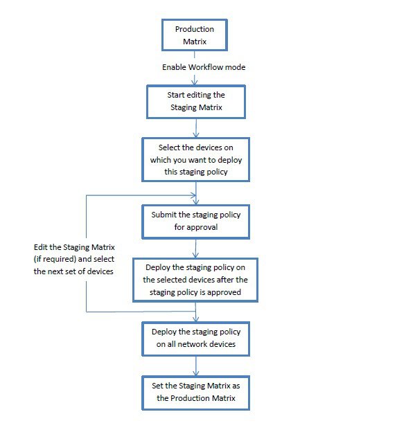
Super Admin user can select the users that are assigned to the editor and approver roles in the Workflow Process Settings page (Work Centers > TrustSec > Settings > Workflow Process).
You cannot edit the SGTs and SGACLs after the staging policy is deployed on the selected devices, however, you can edit the matrix cells. You can use the Configuration Delta report to track the difference between the production matrix and the staging matrix. You can also click on the Delta icon on a cell to view the changes made to that cell during the staging process.
The following table describes the different stages of the workflow:
|
Stage |
Description |
|---|---|
|
Staging in Edit |
The matrix is moved to Staging in Edit state, when an editor starts editing the staging matrix. After editing the staging matrix, the editor can select the devices on which he wants to deploy the new staging policy. |
|
Staging Awaiting Approval |
After editing the matrix, the editor submits the staging matrix to the approver for review and approval. While submitting the staging matrix for approval, the editor can add the comments that will be included in the email sent to the approver. The approver can review the staging policy and approve or reject the request. The approver can also view the selected network devices and the Configuration Delta report. While approving or rejecting a request, the approver can add the comments that will be included in the email sent to the editor. The editor can cancel the approval request as long as the staging policy is not deployed on any of the network devices. |
|
Deploy Approved |
When the approver approves the request, the staging matrix is moved to Deploy Approved state. If the request is rejected, the matrix is moved back to Staging in Edit state. The editor can deploy the staging policy on the selected network devices only after the staging policy is approved by the approver. |
|
Partially Deployed |
After the staging matrix is deployed on the selected devices, the matrix is moved to Partially Deployed state. The matrix remains in the Partially Deployed stage till the staging policy is deployed on all the network devices. You cannot edit the SGTs and SGACLs at this stage, however, you can edit the matrix cells. The devices that are not deployed with the latest policy (out-of-sync devices) are displayed in orange (with italic font) in the Network Device Deployment window. This status is also displayed on the deployment progress status bar. The editor can select these devices and request approval to synchronize the devices that were updated in different deployment cycles. |
|
Fully Deployed |
The above process is repeated till the staging policy is deployed on all the network devices. When the staging matrix is deployed on all the network devices, the approver can set the staging matrix as the production matrix. We recommend that you take a copy of the production matrix before setting the staging matrix as the new production matrix, because after replacing the production matrix with the staging matrix, you cannot rollback to the previous version of the production matrix. |
The options displayed in the Workflow drop-down list vary based on the workflow state and the user role (editor or approver). The following table lists the menu options displayed for an editor and approver:
|
Workflow state |
Menu displayed for Editor |
Menu displayed for Approver |
|---|---|---|
|
Staging in Edit |
|
|
|
Staging Awaiting Approval |
|
|
|
Approved - ready to deploy |
|
|
|
Partially deployed |
|
|
|
Fully deployed |
|
|
The workflow options are also available in the Source and Destination Tree view.
You can view the list of devices that downloaded the staging/production policy by using the TrustSec Policy Download report (Work Centers > TrustSec > Reports). The TrustSec Policy Download lists the requests sent by the network devices for policy (SGT/SGACL) download and the details sent by ISE. If the Workflow mode is enabled, the requests can be filtered for production or staging matrix.
Egress Policy Table Cells Configuration
Cisco ISE allows you to configure cells using various options that are available in the tool bar. Cisco ISE does not allow a cell configuration if the selected source and destination SGTs are identical to a mapped cell.
Add the Mapping of Egress Policy Cells
You can add the mapping cell for Egress Policy from the Policy page.
Procedure
| Step 1 |
Choose Work Centers > TrustSec > TrustSec Policy > Egress Policy. |
| Step 2 |
To select the matrix cells, do the following:
|
| Step 3 |
Click Add to add a new mapping cell. |
| Step 4 |
Select appropriate values for:
|
| Step 5 |
Click Save. |
Export Egress Policy
Procedure
| Step 1 |
Choose Work Centers > TrustSec > TrustSec Policy > Egress Policy > Matrix > Export. |
||
| Step 2 |
Check the Include Empty Cells check box if you want to include the empty cells (which do not have any SGACL configured) in the exported file. When this option is enabled, the whole matrix is exported and the empty cells are marked with the "Empty" keyword in the SGACL column.
|
||
| Step 3 |
Select one of the following options:
|
||
| Step 4 |
Click Export. |
Import Egress Policy
You can create the egress policy offline and then import it in to Cisco ISE. If you have a large number of security group tags, then creating the security group ACL mapping one by one might take some time. Instead, creating the egress policy offline and importing it in to Cisco ISE saves time for you. During import, Cisco ISE appends the entries from the CSV file to the egress policy matrix and does not overwrite the data.
Egress policy import fails if the:
-
Source or destination SGTs do not exist
-
SGACL does not exist
-
Monitor status is different than what is currently configured in Cisco ISE for that cell
Procedure
| Step 1 |
Choose Work Centers > TrustSec > TrustSec Policy > Egress Policy > Matrix > Import. |
| Step 2 |
Click Generate a Template. |
| Step 3 |
Download the template (CSV file) from the Egress Policy page and enter the following information in the CSV file:
|
| Step 4 |
Check the Overwrite Existing Data with New Data check box if you want to overwrite the existing policy with the one that you are importing. If empty cells (cells that are marked with the "Empty" keyword in the SGACL column) are included in the imported file, the existing policy in the corresponding matrix cells will be deleted. While exporting the egress policy, if you want to include the empty cells, check the Include Empty Cells check box. For more information, see Export Egress Policy. |
| Step 5 |
Click Validate File to validate the imported file. Cisco ISE validates the CSV structure, SGT names, SGACL, and file size before importing the file. |
| Step 6 |
Check the Stop Import on First Error check box for Cisco ISE to abort the import if it encounters any errors. |
| Step 7 |
Click Import. |
Configure SGT from Egress Policy
You can create Security Groups directly from the Egress Policy page.
Procedure
| Step 1 |
Choose Work Centers > TrustSec > TrustSec Policy > Egress Policy. |
| Step 2 |
From the Source or Destination Tree View page, choose Configure > Create New Security Group. |
| Step 3 |
Enter the required details and click Submit. |
Monitor Mode
The Monitor All option in the egress policy allows you to change the entire egress policy configuration status to monitor mode with a single click. Check the Monitor All check box in the egress policy page to change the egress policy configuration status of all the cells to monitor mode. When you check the Monitor All check box, the following changes take place in the configuration status:
-
The cells whose status is Enabled will act as monitored but appears as if they are enabled.
-
The cells whose status is Disable will not be affected.
-
The cells whose status is Monitor will remain Monitored.
Uncheck the Monitor All check box to restore the original configuration status. It does not change the actual status of the cell in the database. When you deselect Monitor All, each cell in the egress policy regains its original configuration status.
Features of Monitor Mode
The monitoring functionality of the monitor mode helps you to:
-
Know how much traffic is filtered but monitored by the monitor mode
-
Know that SGT-DGT pair is in monitor mode or enforce mode, and observe if there is any unusual packet drop is happening in the network
-
Understand that SGACL drop is actually enforced by enforce mode or permitted by monitor mode
-
Create custom reports based on the type of mode (monitor, enforce, or both)
-
Identify which SGACL has been applied on NAD and display discrepancy, if any
The Unknown Security Group
The Unknown security group is a pre-configured security group that cannot be modified and represents the Trustsec with tag value 0.
The Cisco security group network devices request for cells that refer to the unknown SGT when they do not have an SGT of either source or destination. If only the source is unknown, the request applies to the <unknown, Destination SGT> cell. If only the destination is unknown, the request applies to the <source SGT, unknown> cell. If both the source and destination are unknown, the request applies to the <Unknown, Unknown> cell.
Default Policy
Default Policy refers to the <ANY,ANY> cell. Any source SGT is mapped to any destination SGT. Here, the ANY SGT cannot be modified and it is not listed in any source or destination SGTs. The ANY SGT can only be paired with ANY SGT. It cannot be paired with any other SGTs. A TrustSec network device attaches the default policy to the end of the specific cell policy.
-
If a cell is empty, that means it contains the default policy alone.
-
If a cell contains some policy, the resulting policy is a combination of the cell specific policy followed by the default policy.
According to Cisco ISE, the cell policy and the default policy are two separate sets of SGACLs that the devices get in response to two separate policy queries.
Configuration of the default policy is different from other cells:
-
Status can take only two values, Enabled or Monitored.
-
Security Group ACLs is an optional field for the default policy, so can be left empty.
-
Final Catch All Rule can be any of the following: Permit IP, Deny IP, Permit IP log, or Deny IP log. Clearly the None option is not available here because there is no safety net beyond the default policy.
Push Button
The Push option in the egress policy initiates a CoA notification that calls the Trustsec devices to immediately request for updates from Cisco ISE regarding the configuration changes in the egress policy.
SGT Assignment
Cisco ISE allows you to assign an SGT to a TrustSec device if you know the device hostname or IP address. When a device with the specific hostname or IP address joins the network, Cisco ISE will assign the SGT before authenticating it.
The following SGTs are created by default:
- SGT_TrustSecDevices
-
SGT_NetworkServices
-
SGT_Employee
-
SGT_Contractor
-
SGT_Guest
-
SGT_ProductionUser
-
SGT_Developer
-
SGT_Auditor
-
SGT_PointofSale
-
SGT_ProductionServers
-
SGT_DevelopmentServers
-
SGT_TestServers
-
SGT_PCIServers
-
SGT_BYOD
-
SGT_Quarantine
Sometimes, devices need to be manually configured to map the security group tags to the endpoint. You can create this mapping from the Security Group Mappings page. Before you perform this action, ensure that you have reserved a range of SGTs.
ISE allows you to create up to 10,000 IP-to-SGT mappings. You can create IP-to-SGT mapping groups to logically group such large scale mappings. Each group of IP-to-SGT mappings contains a list of IP addresses, a single security group it would map to and a network device or network device group which is the deployment target for those mappings.
NDAC Authorization
You can configure the TrustSec policy by assigning SGTs to devices. You can assign security groups to devices based on TrustSec device ID attribute.
Configure NDAC Authorization
Before you begin
-
Ensure that you create the security groups for use in the policy.
-
To perform the following task, you must be a Super Admin or System Admin.
Procedure
| Step 1 |
Choose Work Centers > TrustSec > TrustSec Policy > Network Device Authorization. |
| Step 2 |
Click the Action icon on the right-hand side of the Default Rule row, and click Insert New Row Above. |
| Step 3 |
Enter the name for this rule. |
| Step 4 |
Click the plus sign (+) next to Conditions to add a policy condition. |
| Step 5 |
You can click Create New Condition (Advance Option) and create a new condition. |
| Step 6 |
From the Security Group drop-down list, select the SGT that you want to assign if this condition evaluates to true. |
| Step 7 |
Click the
Action icon from this row to add additional rules
based on device attributes either above or below the current rule. You can
repeat this process to create all the rules that you need for the TrustSec
policy. You can drag and drop the rules to reorder them by clicking the
The first rule that evaluates to true determines the result of the evaluation. If none of the rules match, the default rule will be applied; you can edit the default rule to specify the SGT that must be applied to the device if none of the rules match. |
| Step 8 |
Click Save to save your TrustSec policy. If a TrustSec device tries to authenticate after you have configured the network device policy, the device will get its SGT and the SGT of its peers and will be able to download all the relevant details. |
Configure End User Authorization
Cisco ISE allows you to assign a security group as the result of an authorization policy evaluation. Using this option, you can assign a security group to users and end points.
Before you begin
-
Read the information on authorization policies.
-
To perform the following task, you must be a Super Admin or System Admin.
Procedure
| Step 1 |
Choose Work Centers > TrustSec > Authorization Policy. |
| Step 2 |
Create a new authorization policy. |
| Step 3 |
Select a security group, for Permissions. If the conditions specified in this authorization policy is true for a user or endpoint, then this security group will be assigned to that user or endpoint and all data packets that are sent by this user or endpoint will be tagged with this particular SGT. |
TrustSec Configuration and Policy Push
Cisco ISE supports Change of Authorization (CoA) which allows Cisco ISE to notify TrustSec devices about TrustSec configuration and policy changes, so that the devices can reply with requests to get the relevant data.
A CoA notification can trigger a TrustSec network device to send either an Environment CoA or a Policy CoA.
You can also push a configuration change to devices that do not intrinsically support the TrustSec CoA feature.
CoA Supported Network Devices
Cisco ISE sends CoA notifications to the following network devices:
-
Network device with single IP address (subnets are not supported)
-
Network device configured as a TrustSec device
-
Network device set as CoA supported
When Cisco ISE is deployed in a distributed environment where there are several secondaries that interoperate with different sets of devices, CoA requests are sent from Cisco ISE primary node to all the network devices. Therefore, TrustSec network devices need to be configured with the Cisco ISE primary node as the CoA client.
The devices return CoA NAK or ACK back to the Cisco ISE primary node. However, the following TrustSec session coming from the network device would be sent to the Cisco ISE node to which the network devise sends all it's other AAA requests and not necessarily to the primary node.
Push Configuration Changes to Non-CoA Supporting Devices
Some platforms do not support Cisco ISE's "Push" feature for Change of Authorization (CoA), for example: some versions of the Nexus network device. For this case, ISE will connect to the network device and make it to trigger an updated configuration request towards ISE. To achieve this, ISE opens an SSHv2 tunnel to the network device, and the Cisco ISE sends a command that triggers a refresh of the TrustSec policy matrix. This method can also be carried out on network platforms that support CoA pushing.
Procedure
| Step 1 |
Choose . |
| Step 2 |
Check the checkbox next to the required network device and click Edit. Verify that the network device's name, IP address, RADIUS and TrustSec settings are properly configured. |
| Step 3 |
Scroll down to Advanced TrustSec Settings, and in the TrustSec Notifications and Updates section, check the Send configuration changes to device checkbox, and click the CLI (SSH) radio button. |
| Step 4 |
(Optional) Provide an SSH key. |
| Step 5 |
Check the Include this device when deploying Security Group Tag Mapping Updates check box, for this SGA device to obtain the IP-SGT mappings using device interface credentials. |
| Step 6 |
Enter the username and password of the user having privileges to edit the device configuration in the Exec mode. |
| Step 7 |
(Optional) Enter the password to enable Exec mode password for the device that would allow you to edit its configuration. You can click Show to display the Exec mode password that is already configured for this device. |
| Step 8 |
Click Submit at the bottom of the page. |
The network device is now configured to push Trustsec changes. After you change a Cisco ISE policy, click Push to have the new configuration reflected on the network device.
SSH Key Validation
You may want to harden security by using an SSH key. Cisco ISE supports this with its SSH key validation feature.
To use this feature, you open an SSHv2 tunnel from the Cisco ISE to the network device, then use the network device's own CLI to retrieve the SSH key. You then copy this key and paste it into Cisco ISE for validation. Cisco ISE terminates the connection if the SSH key is wrong.
Limitation: Currently, Cisco ISE can validate only one IP (not on ranges of IP, or subnets within an IP)
Before you begin
You will require:
-
Login credentials
-
CLI command to retrieve the SSH key
for the network device with which you want the Cisco ISE to communicate securely.
Procedure
| Step 1 |
On the network device: |
| Step 2 |
From the Cisco ISE user interface:
|
The network device is now communicating with the Cisco ISE using SSH key validation.
Environment CoA Notification Flow
The following figure depicts the Environment CoA notification flow.
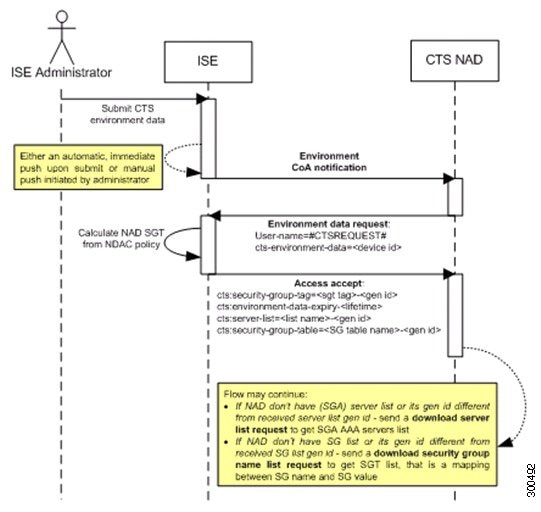
-
Cisco ISE sends an environment CoA notification to the TrustSec network device.
-
The device returns an environment data request.
-
In response to the environment data request, Cisco ISE returns:
The environment data of the device that sent the request—This includes the TrustSec device’s SGT (as inferred from the NDAC policy) and download environment TTL.
The name and generation ID of the TrustSec AAA server list.
The names and generation IDs of (potentially multiple) SGT tables—These tables list SGT name versus SGT value, and together these tables hold the full list of SGTs.
-
If the device does not hold a TrustSec AAA server list, or the generation ID is different from the generation ID that is received, the device sends another request to get the AAA server list content.
-
If the device does not hold an SGT table listed in the response, or the generation ID is different from the generation ID that is received, the device sends another request to get the content of that SGT table.
Environment CoA Triggers
An Environment CoA can be triggered for:
-
Network devices
-
Security groups
-
AAA servers
Trigger Environment CoA for Network Devices
To trigger an Environment CoA for the Network devices, complete the following steps:
Procedure
| Step 1 |
Choose . |
| Step 2 |
Add or edit a network device. |
| Step 3 |
Update TrustSec Notifications and Updates parameters under the Advanced TrustSec Settings section. Changing the environment attribute is notified only to the specific TrustSec network device where the change took place. Because only a single device is impacted, an environmental CoA notification is sent immediately upon submission. The result is a device update of its environment attribute. |
Trigger Environment CoA for Security Groups
To trigger an Environment CoA for the security groups, complete the following steps.
Procedure
| Step 1 |
Choose Work Centers > TrustSec > Components > Security Groups. |
| Step 2 |
In the Security Group page, change the name of an SGT, which will change the name of the mapping value of that SGT. This triggers an environmental change. |
| Step 3 |
Click the Push button to initiate an environment CoA notification after changing the names of multiple SGTs. This environment CoA notification goes to all TrustSec network devices and provides an update of all SGTs that were changed. |
Trigger Environment CoA for TrustSec AAA Servers
To trigger an Environment CoA for the TrustSec AAA servers, complete the following steps.
Procedure
| Step 1 |
Choose Work Centers > TrustSec > Components > TrustSec AAA Servers. |
| Step 2 |
In the TrustSec AAA Servers page create, delete or update the configuration of a TrustSec AAA server. This triggers an environment change. |
| Step 3 |
Click the Push button to initiate an environment CoA notification after you configure multiple TrustSec AAA servers. This environment CoA notification goes to all TrustSec network devices and provides an update of all TrustSec AAA servers that were changed. |
Trigger Environment CoA for NDAC Policy
To trigger an Environment CoA for the NDAC Policies, complete the following steps.
Procedure
| Step 1 |
Choose Work Centers > TrustSec > Policy > Network Device Authorization. In the NDAC policy page you can create, delete, or update rules of the NDAC policy. These environment changes are notified to all network devices. |
| Step 2 |
Choose Work Centers > TrustSec > TrustSec Policy > Network Device Authorization. In the NDAC policy page you can create, delete, or update rules of the NDAC policy. These environment changes are notified to all network devices. |
| Step 3 |
You can initiate an environment CoA notification by clicking the Push button in the NDAC policy page. This environment CoA notification goes to all TrustSec network devices and provides an update of network device own SGT. |
Update SGACL Content Flow
The following figure depicts the Update SGACL Content flow.
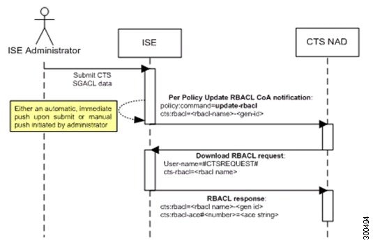
-
Cisco ISE sends an update SGACL named list CoA notification to a TrustSec network device. The notification contains the SGACL name and the generation ID.
-
The device may replay with an SGACL data request if both of the following terms are fulfilled:
If the SGACL is part of an egress cell that the device holds. The device holds a subset of the egress policy data, which are the cells related to the SGTs of its neighboring devices and endpoints (egress policy columns of selected destination SGTs).
The generation ID in the CoA notification is different from the generation ID that the device holds for this SGACL.
-
In response to the SGACL data request, Cisco ISE returns the content of the SGACL (the ACE).
Initiate an Update SGACL Named List CoA
To trigger an Update SGACL Named List CoA, complete the following steps:
Procedure
| Step 1 |
Choose Work Centers > TrustSec > Components > Security Group ACLs. |
| Step 2 |
Change the content of the SGACL. After you submit a SGACL, it promotes the generation ID of the SGACL. |
| Step 3 |
Click the Push button to initiate an Update SGACL Named List CoA notification after you change the content of multiple SGACLs. This notification goes to all TrustSec network devices, and provides an update of that SGACL content on the relevant devices. Changing the name or the IP version of an SGACL does not change its generation ID; hence it does not require sending an update SGACL named list CoA notification. However, changing the name or IP version of an SGACL that is in use in the egress policy indicates a change in the cell that contains that SGACL, and this changes the generation ID of the destination SGT of that cell. |
Policies Update CoA Notification Flow
The following figure depicts the Policies CoA Notification flow.
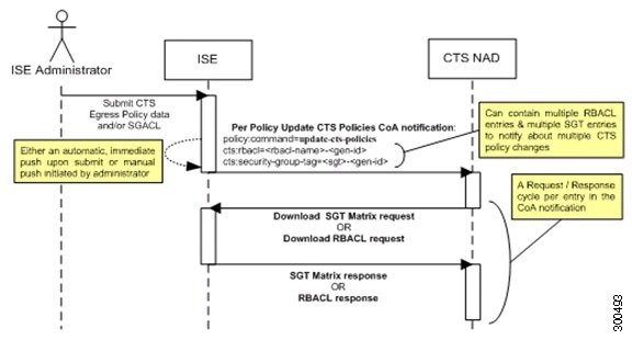
-
Cisco ISE sends an update policies CoA notification to a TrustSec network device. The notification may contain multiple SGACL names and their generation IDs, and multiple SGT values and their generation IDs.
-
The device may replay with multiple SGACL data requests and/or multiple SGT data.
-
In response to each SGACL data request or SGT data request, Cisco ISE returns the relevant data.
Update SGT Matrix CoA Flow
The following figure depicts the Update SGT Matrix CoA flow.
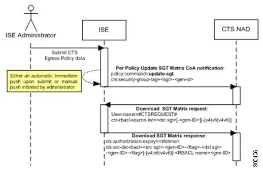
-
Cisco ISE sends an updated SGT matrix CoA notification to a TrustSec network device. The notification contains the SGT value and the generation ID.
-
The device may replay with an SGT data request if both the following terms are fulfilled:
If the SGT is the SGT of a neighboring device or endpoint, the device downloads and hold the cells related to SGTs of neighboring devices and endpoints (a destination SGT).
The generation ID in the CoA notification is different from the generation ID that the device holds for this SGT.
-
In response to the SGT data request, Cisco ISE returns the data of all egress cells, such as the source and destination SGTs, the status of the cell, and an ordered list of the SGACL names configured in that cell.
Initiate Update SGT Matrix CoA from Egress Policy
Procedure
| Step 1 |
Choose Work Centers > TrustSec > TrustSec Policy > Egress Policy. |
| Step 2 |
On the Egress Policy page, change the content of a cell (status, SGACLs). |
| Step 3 |
After you submit the changes, it promotes the generation ID of the destination SGT of that cell. |
| Step 4 |
Click the Push button to initiate the Update SGT matrix CoA notification after you change the content of multiple egress cells. This notification goes to all TrustSec network devices, and provides an update of cells content on the relevant devices. |
TrustSec CoA Summary
The following table summarizes the various scenarios that may require initiating a TrustSec CoA, the type of CoA used in each scenario, and the related UI pages.
|
UI Page |
Operation that triggers CoA |
How it is triggered |
CoA type |
Send to |
|---|---|---|---|---|
|
Network Device |
Changing the environment TTL in the TrustSec section of the page |
Upon successful Submit of TrustSec network device |
Environment |
The specific network device |
|
TrustSec AAA Server |
Any change in the TrustSec AAA server (create, update, delete, reorder) |
Accumulative changes can be pushed by clicking the Push button on the TrustSec AAA servers list page. |
Environment |
All TrustSec network devices |
|
Security Group |
Any change in the SGT (create, rename, delete) |
Accumulative changes can be pushed by clicking the Push button on the SGT list page. |
Environment |
All TrustSec network devices |
|
NDAC Policy |
Any change in the NDAC policy (create, update, delete) |
Accumulative changes can be pushed by clicking the Push button on the NDAC policy page. |
Environment |
All TrustSec network devices |
|
SGACL |
Changing SGACL ACE |
Accumulative changes can be pushed by clicking the Push button on the SGACL list page. |
Update RBACL named list |
All TrustSec network devices |
|
Changing SGACL name or IP version |
Accumulative changes can be pushed by clicking the Push button on the SGACL list page or the policy push button in the Egress table. |
Update SGT matrix |
All TrustSec network devices |
|
|
Egress Policy |
Any operation that changes the generation ID of an SGT |
Accumulative changes can be pushed by clicking the Push button on the egress policy page. |
Update SGT matrix |
All TrustSec network devices |
Security Group Tag Exchange Protocol
Security Group Tag (SGT) Exchange Protocol (SXP) is used to propagate the SGTs across network devices that do not have hardware support for TrustSec. SXP is used to transport an endpoint's SGT along with the IP address from one SGT-aware network device to another. The data that SXP transports is called as IP-SGT mapping. The SGT to which an endpoint belongs can be assigned statically or dynamically, and the SGT can be used as a classifier in network policies.
To enable SXP service on a node, check the Enable SXP Service check box in the General Node Settings page. You must also specify the interface to be used for SXP service.
SXP uses TCP as its transport protocol to set up SXP connection between two separate network devices. Each SXP connection has one peer designated as SXP speaker and the other peer as SXP listener. The peers can also be configured in a bi-directional mode where each of them act as both speaker and listener. Connections can be initiated by either peers, but mapping information is always propagated from a speaker to a listener.
Note |
Session bindings are always propagated on the default SXP domain. |
The following table lists some of the common terms used in the SXP environment:
|
IP-SGT mapping |
The IP Address to SGT mapping that is exchanged over SXP connection. To view all the mappings learned by the SXP devices (including static mappings and session mappings), choose Work Centers > TrustSec > SXP > All SXP Mappings. |
|
SXP Speaker |
The peer that sends the IP-SGT mappings over the SXP connection. |
|
SXP Listener |
The peer that receives the IP-SGT mappings over the SXP connection. |
To view the SXP peer devices that are added to Cisco ISE, choose Work centers > TrustSec > SXP > SXP Devices.
Note |
We recommend that you run the SXP service on a standalone node. |
-
Cisco ISE does not support multiple SXP session bindings with same IP address.
-
If the RADIUS accounting updates are too frequent (for example, around 6 to 8 accounting updates in few seconds), sometimes the accounting update packet might be dropped and SXP might not receive the IP-SGT binding.
-
After upgrading from a previous version of ISE, SXP does not start automatically. After the upgrade, you must change the SXP password and restart the SXP process.
Add an SXP Device
Before you begin
To perform the following task, you must be a Super Admin or System Admin.
Procedure
| Step 1 |
Choose Work Centers > TrustSec > SXP > SXP Devices. |
| Step 2 |
Click Add. |
| Step 3 |
Enter the device details:
|
| Step 4 |
(Optional) Click Advanced Settings and enter the following details:
|
| Step 5 |
Click Save. |
Add an SXP Domain Filter
You can view all the mappings learned by the SXP devices (including static mappings and session mappings) on the Work Centers > TrustSec > SXP > All SXP Mappings page.
By default, session mappings learnt from the network devices are sent only to the default VPN group. You can create SXP domain filters to send the mappings to different SXP domains (VPNs).
To add an SXP domain filter:
Before you begin
To perform the following task, you must be a Super Admin or System Admin.
Procedure
| Step 1 |
Choose Work Centers > TrustSec > SXP > All SXP Mappings. |
| Step 2 |
Click Add SXP Domain Filter. |
| Step 3 |
Do the following:
|
| Step 4 |
Click Save. |
Configure SXP Settings
Before you begin
To perform the following task, you must be a Super Admin or System Admin.
Procedure
| Step 1 |
Choose Work Centers > TrustSec > Settings > SXP Settings. |
||
| Step 2 |
Enter the required details in the SXP Settings page. If you uncheck the Publish SXP Bindings on PxGrid check box, the IP-SGT mappings will not be propagated across the network devices. |
||
| Step 3 |
Click Save.
|
TrustSec-ACI Integration
Cisco ISE can synchronize SGTs and SXP mappings with the Internal Endpoint Groups (IEPGs), External Endpoint Groups (EEPGs), and endpoint (EP) configuration of Cisco Application Centric Infrastructure (ACI).
Cisco ISE supports packets coming from the ACI domain to the TrustSec domain by synchronizing the IEPGs, and creating correlating read-only SGTs in ISE. These SGTs map the endpoints configured in ACI, and create correlating SXP mappings in ISE. The SGTs displayed on the Security Groups page (with the value "ACI" in the Learned From field). You can view the SXP mappings on the All SXP Mappings page. These mappings are sent to ACI only if the Policy Plane option is selected (in the ACI Settings page) and the SXP device belongs to an SXP domain, that you configured on the ACI Settings page.
Note |
You cannot use read-only SGTs in IP-SGT mappings, mapping groups, and SXP local mappings. |
When you add a Security Group, you can specify whether the SGT is sent to ACI by enabling the Propagate to ACI option. When this option is enabled, the SXP mappings that are related to this SGT are sent to ACI. But, only if the Policy Plane option is selected (in the ACI Settings page) and the SXP device belongs to an SXP Domain, which you configure on the ACI Settings page.
ACI supports the packets that are sent from the TrustSec domain to the ACI domain by synchronizing the SGTs, and creating correlating EEPGs. ACI creates subnets under EEPG based on the SXP mappings from Cisco ISE. These subnets are not deleted from ACI, when the corresponding SXP mappings are deleted in Cisco ISE.
When an IEPG is updated in ACI, the corresponding SGT configuration is updated in Cisco ISE. A new EEPG is created in ACI, when an SGT is added in Cisco ISE. When an SGT is deleted, the corresponding EEPG is deleted in ACI. When an endpoint is updated in ACI, the corresponding SXP mapping is updated in Cisco ISE.
If the connection with the ACI server is lost, Cisco ISE re-synchronizes the data again when the connection is reestablished.
Note |
You must enable the SXP service to use the ACI integration feature. |
Configure ACI Settings
Before you begin
To perform the following task, you must be a Super Admin or System Admin.
Procedure
| Step 1 |
Import the ACI certificate in to the Trusted Certificates Store. Choose Administration > System > Certificates > Trusted Certificates > Import to import the certificate. |
||
| Step 2 |
Choose Work Centers > TrustSec > Settings > ACI Settings. |
||
| Step 3 |
Check the TrustSec-ACI Policy Element Exchange check box to synchronize SGTs and SXP mappings with IEPGs, EEPGs, and endpoint configuration of ACI. |
||
| Step 4 |
Select one of the following options:
|
||
| Step 5 |
Enter the following details if you have selected the Policy Plane option:
|
||
| Step 6 |
Enter the following details if you have selected the Data Plane option:
|
||
| Step 7 |
Click Save. |
Run Top N RBACL Drops by User Report
You can run the Top N RBACL Drops by User report to see the policy violations (based on packet drops) by specific users.
Procedure
| Step 1 |
Choose Operations > Reports > TrustSec. |
| Step 2 |
Click Top N RBACL Drops by User. |
| Step 3 |
From the Filters drop-down menu, add the required monitor modes. |
| Step 4 |
Enter the values for the selected parameters accordingly. You can specify the mode from the Enforcement mode drop-down list as Enforce, Monitor, or Both. |
| Step 5 |
From the Time Range drop-down menu, choose a time period over which the report data will be collected. |
| Step 6 |
Click Run to run the report for a specific period, along with the selected parameters. |
 Feedback