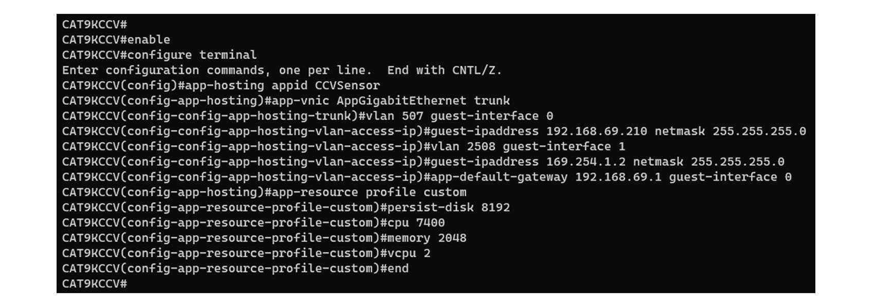
Procedure with the Cisco Cyber Vision sensor management extension
After the Initial configuration, proceed to the steps described in this section.
 Note |
To be able to use the sensor management extension, an IP address reachable by the Center Collection interface must be set on the Collection VLAN. |
Note |
Since the extension deployment is based on HTTPS, flow must be allowed on port TCP 443. We can use an Access Control List (ACL) on IOS XE devices to limit access from . Configuration example for IOS XE devices: Filter Traffic Destined to Cisco IOS XE Devices WebUI Using an Access List - Cisco Where CENTER_ETH0_IP is the administration IP address of your Cyber Vision center (eth0). |
Install the sensor management extension
To install the sensor management extension, you must:
Procedure
|
Step 1 |
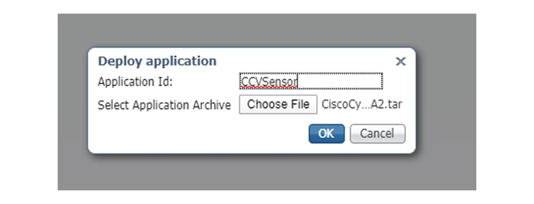
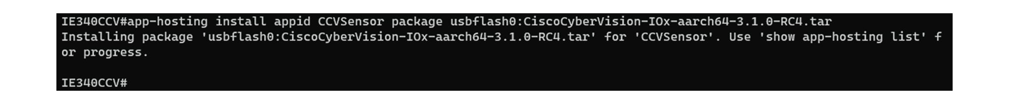
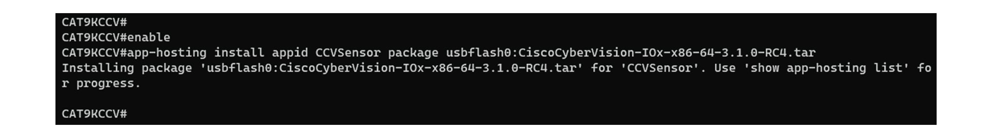
Retrieve the extension file (i.e. CiscoCyberVision-sensor-management-<version>.ext) from cisco.com. |
|
Step 2 |
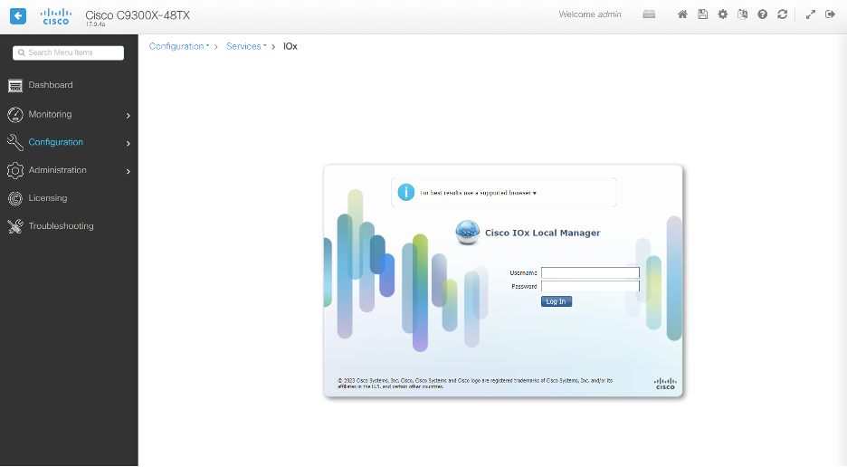
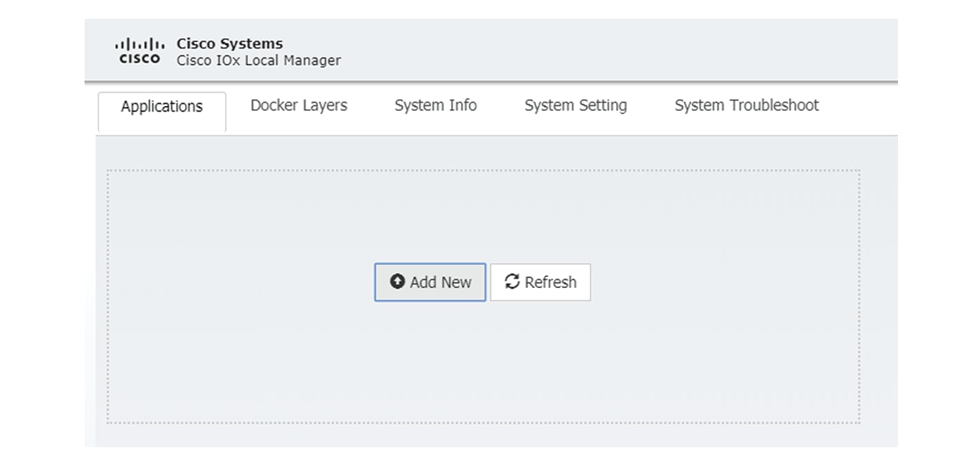
Access the Extension administration page in . |
|
Step 3 |
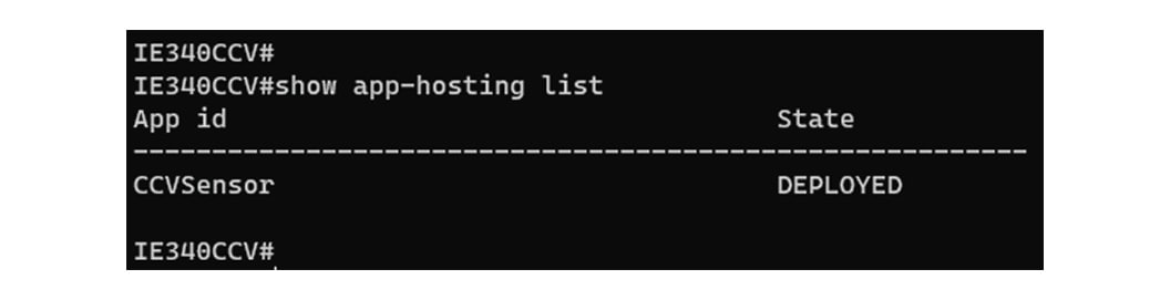
Import the extension file. 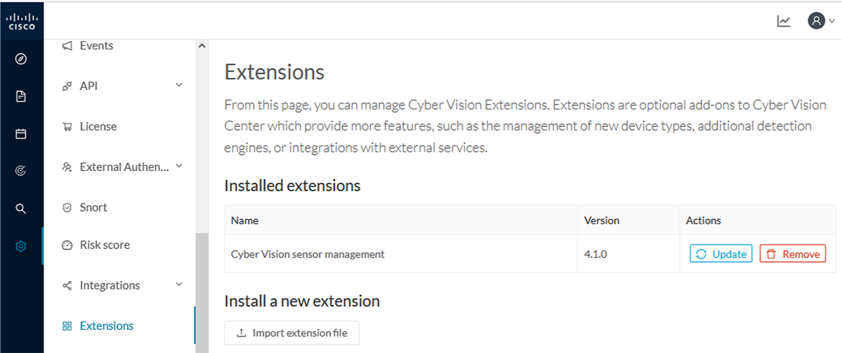 Once the sensor management extension is installed, you will find a new management job under the sensor administration menu (Management Jobs), and the Install via extension button will be enabled in the Sensor Explorer page. |
Management Jobs
Since some deployment tasks on sensors can take several minutes, this page displays the execution status and progress for each sensor deployed with the Sensor Management Extension. The page is visible only when the Sensor Management Extension is installed in the Cisco Cyber Vision Center.
To access the Management jobs page, choose Admin > Sensors > Management jobs from the main menu.
You will find the following jobs:
-
Single deployment:
This job is launched when clicking the Deploy Cisco device button in the sensor administration page, that is when a new IOx sensor is deployed.
-
Single redeployment:
This job is launched when clicking the Reconfigure Redeploy button in the sensor administration page, that is when deploying on a sensor that has already been deployed. This option is used for example to change the sensor's parameters like enabling active discovery.
-
Single removal:
This job is launched when clicking the Remove button from the sensor administration page.
-
Update all devices:
This job is launched when clicking the Update Cisco devices button from the sensor administration page. A unique job is created for all managed sensors that are being updated.
If a job fails, you can click on the error icon to view detailed logs.
Install sensors with the sensor management extension
Before you begin
-
Ensure is integrated with Secure Equipment Access on the IoT Operations Dashboard. For more information, see the "Integrate Cisco Cyber Vision Center with Secure Equipment Access" topic in the Cisco Cyber Vision Administration Guide, 5.3.0.
-
Confirm you have administrator access to Cisco Cyber Vision Center.
Procedure
|
Step 1 |
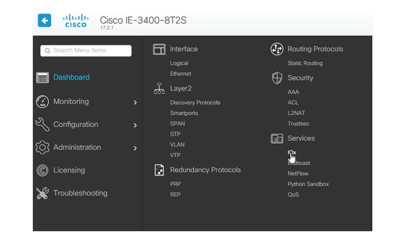
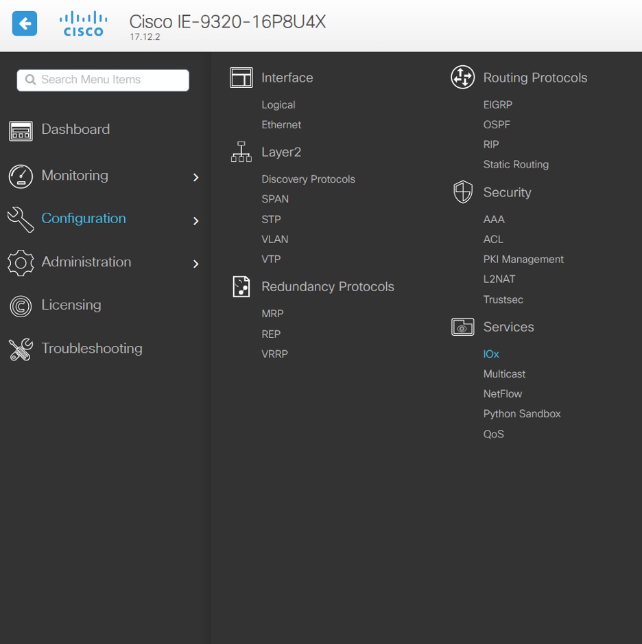
In , navigate to Admin > Sensors > Sensor Explorer and click New sensor, then Install via extension. |
||
|
Step 2 |
To configure your Center to reach your network device, fill in the required fields. For field descriptions, see Network device configuration fields for sensor installation. |
||
|
Step 3 |
Click Connect. |
||
|
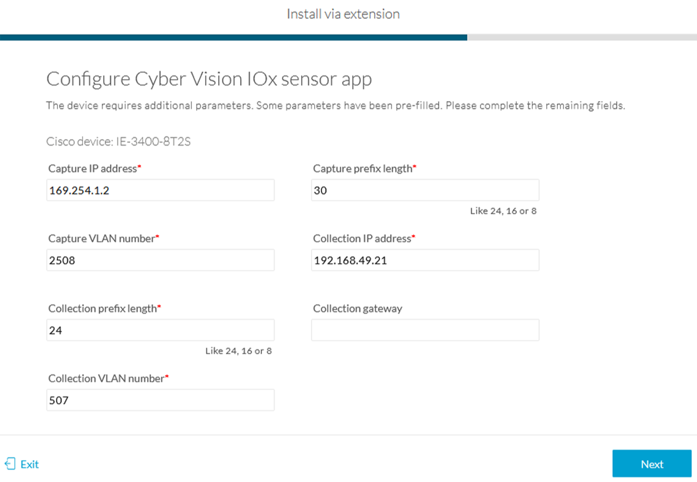
Step 4 |
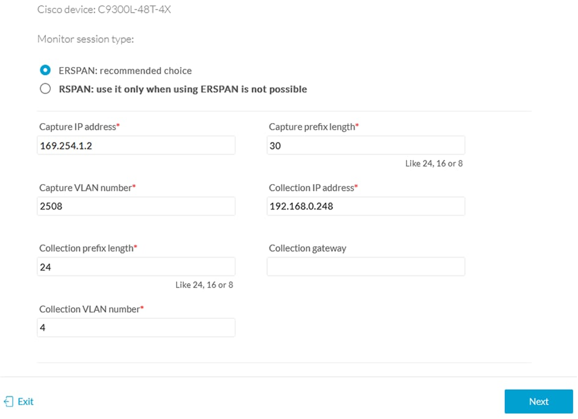
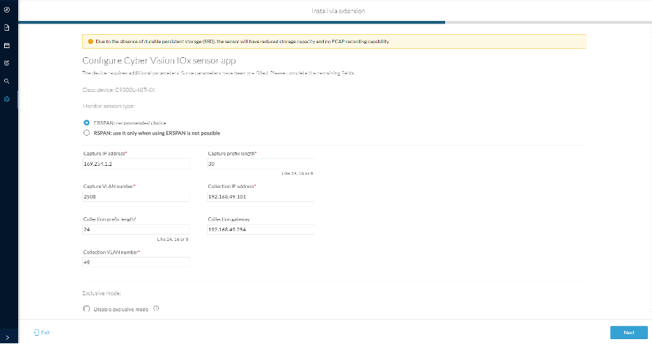
To configure the IOx sensor app for the Cisco IE device, enter these network details, and click Next. Some parameters are pre-filled with default values. You can either keep these values or change them as needed.
|
||
|
Step 5 |
To also install the SEA agent app along with the sensor app, click With SEA, and choose one of these options, and click Next.
|
||
|
Step 6 |
To configure the active discovery settings, enter these details on the Active Discovery page:
|
||
|
Step 7 |
Click Deploy. |
What to do next
Network device configuration fields for sensor installation
The following table describes the fields required when installing sensors using the Sensor Management Extension in Cisco Cyber Vision.
|
Field |
Description |
Required or Optional |
Comments |
||
|---|---|---|---|---|---|
|
IP Address |
Management IP address of the device. |
Required |
NIL |
||
|
Port |
Management port of the device |
Required |
443 or 8443 |
||
|
Center Collection IP |
Collection IP address of the Center |
Optional |
NIL |
||
|
Sensor Label |
A label for the sensor |
Optional |
For example, CVPlusSEA |
||
|
Template |
Select a configuration template. |
Required |
Select the default template |
||
|
Credentials |
Specify the credentials to authenticate with the sensor app |
Required |
Use global (recommended) or custom.
|
||
|
Capture modes |
Select the capture mode to determine which flows analyzes. |
Required. |
Select one of the these options:
|
Configure a sensor in the sensor management extension
If the Center can join the switch, the following form appears:
Form for the Cisco IE3x00 and the Cisco IE9x00:
Form for the Cisco Catalyst 9x00 with RSPAN configuration available:
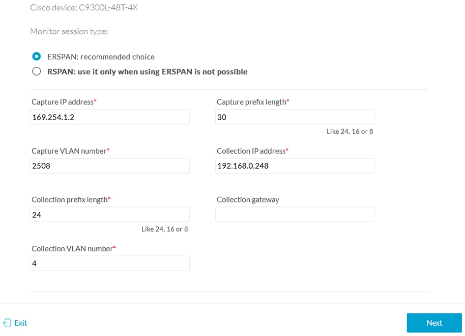
While some parameters are filled automatically, you can still change them if necessary.
Procedure
|
Step 1 |
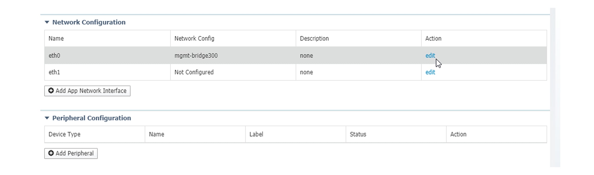
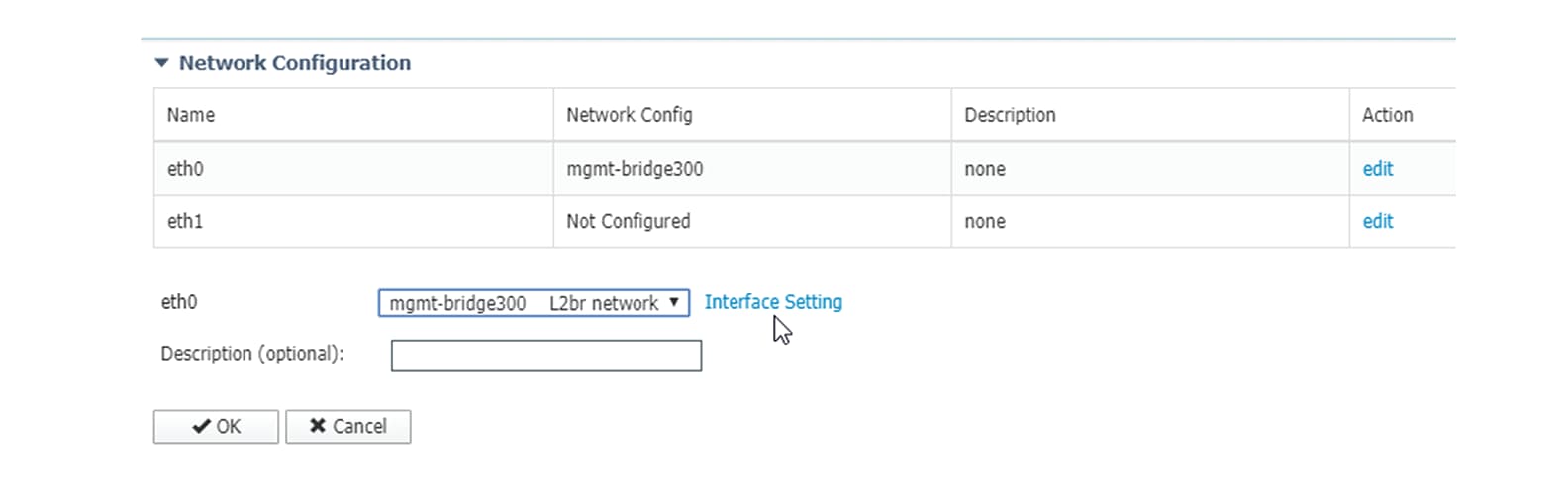
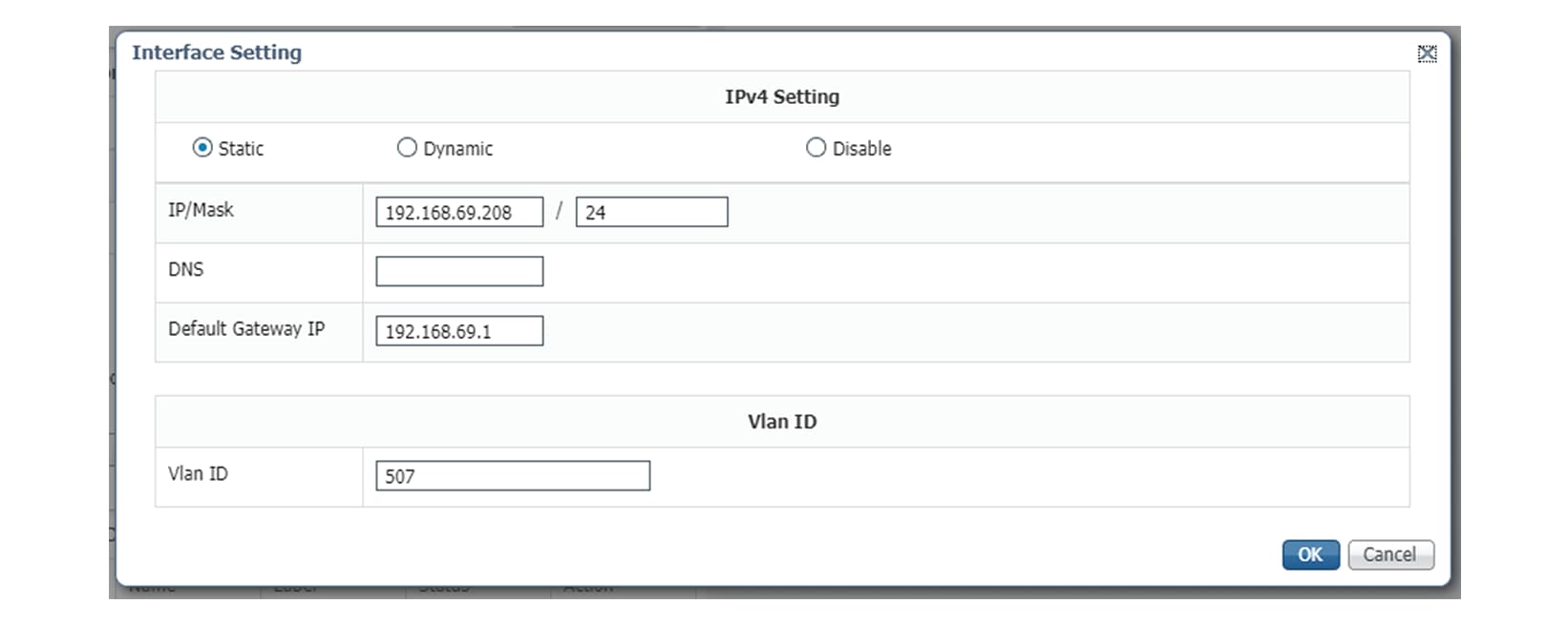
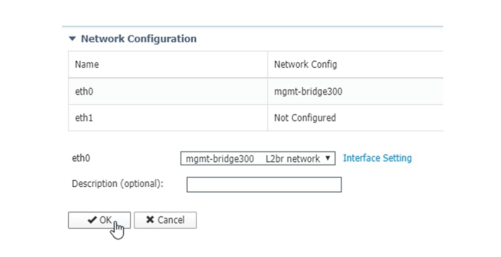
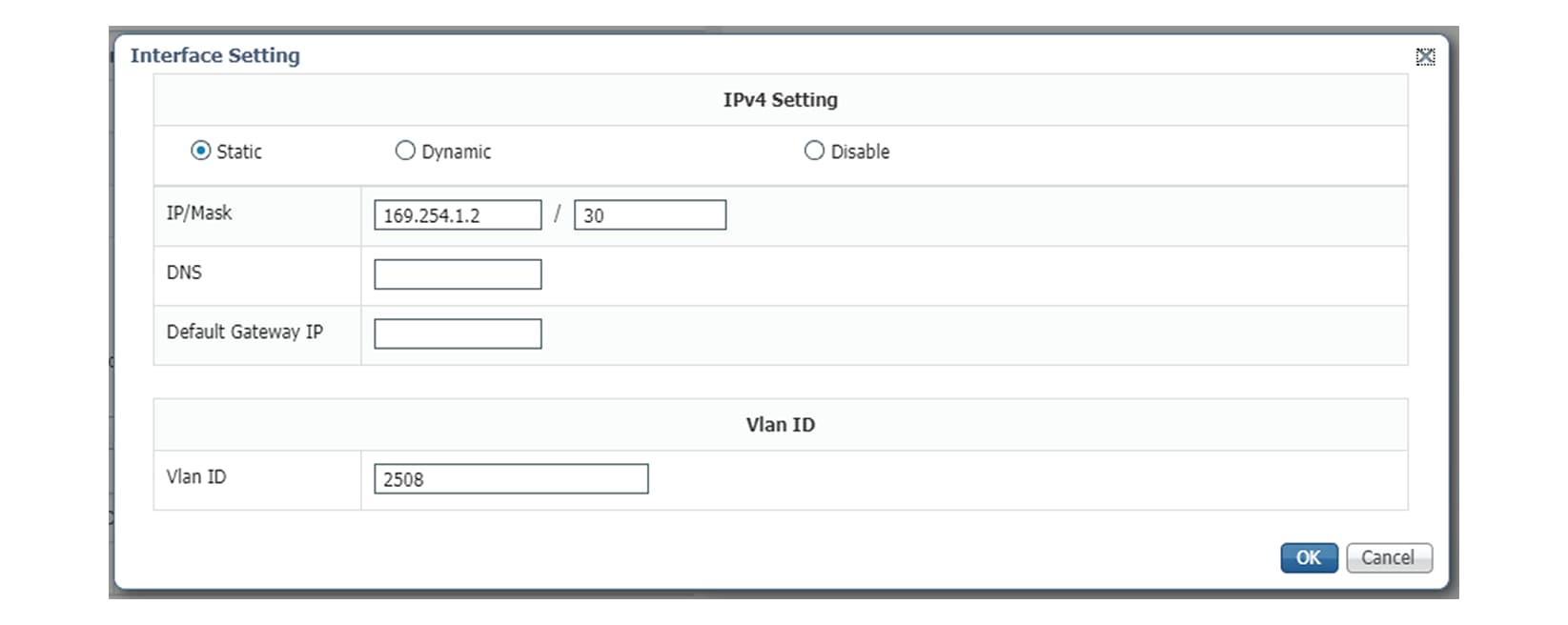
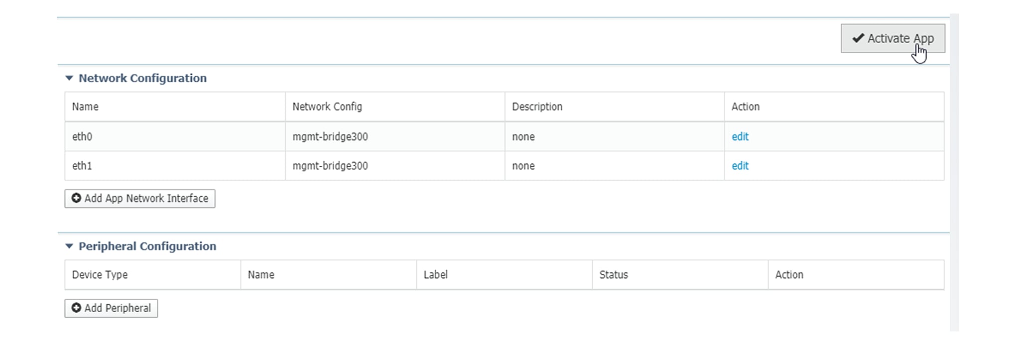
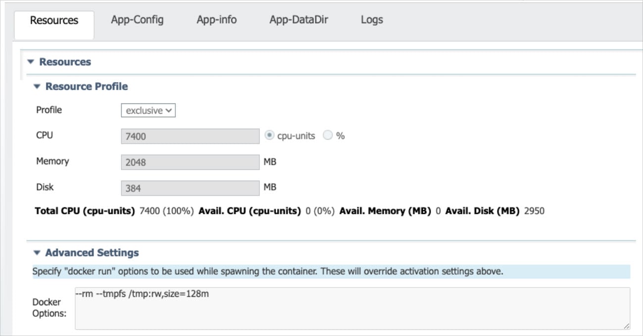
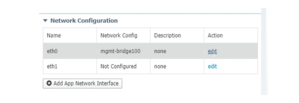
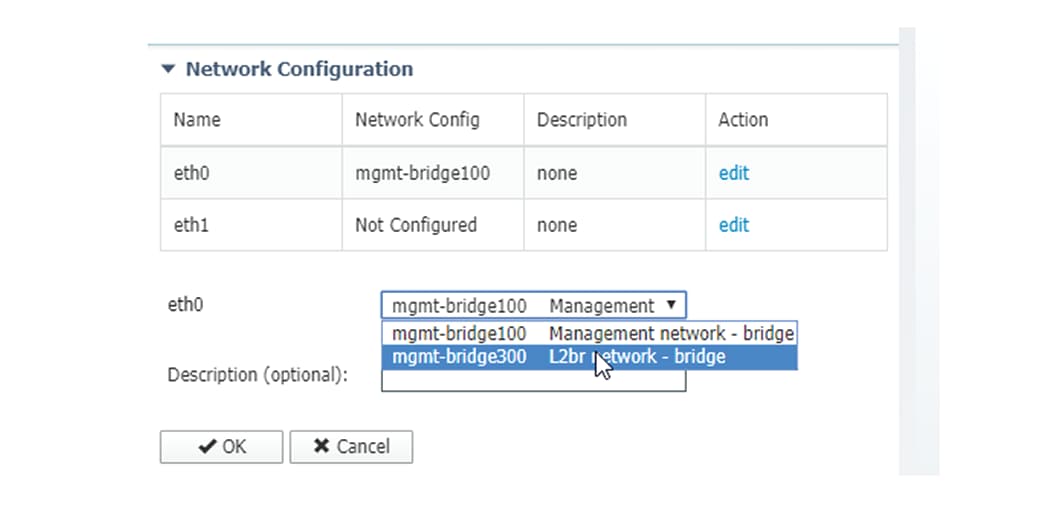
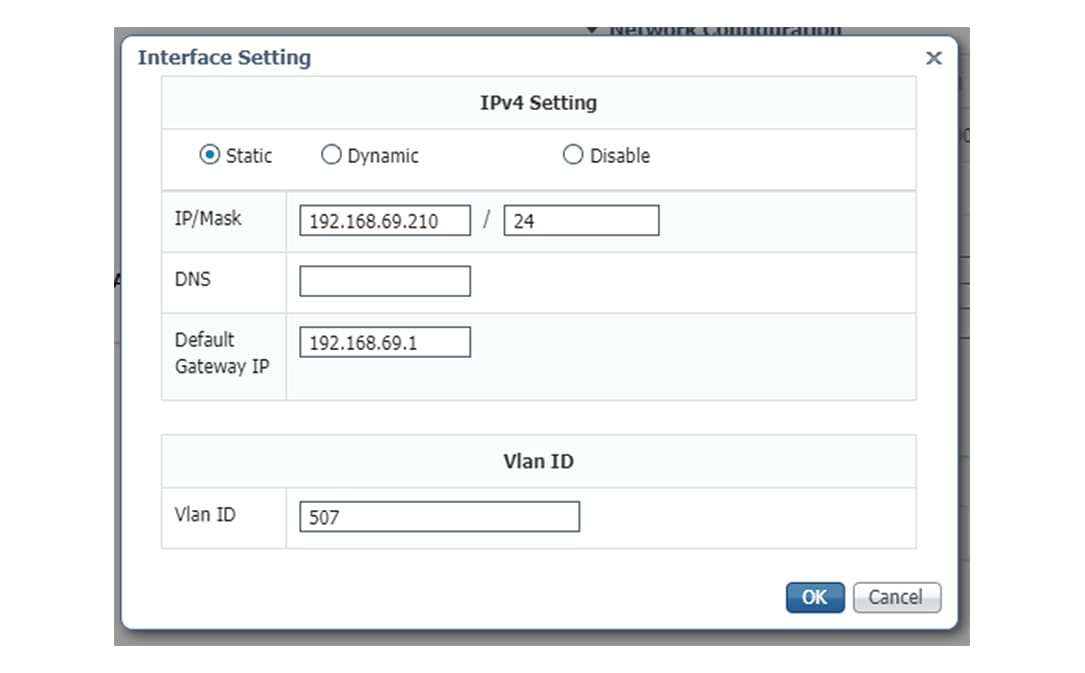
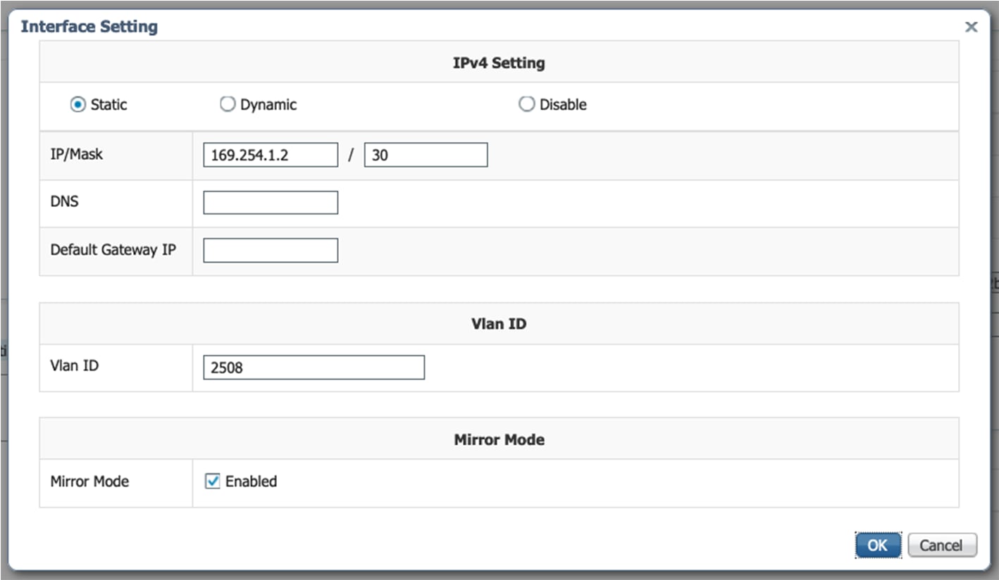
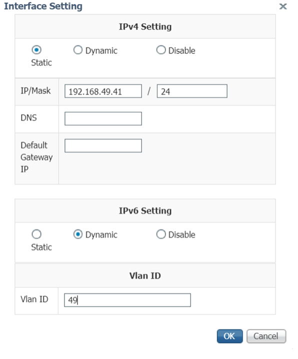
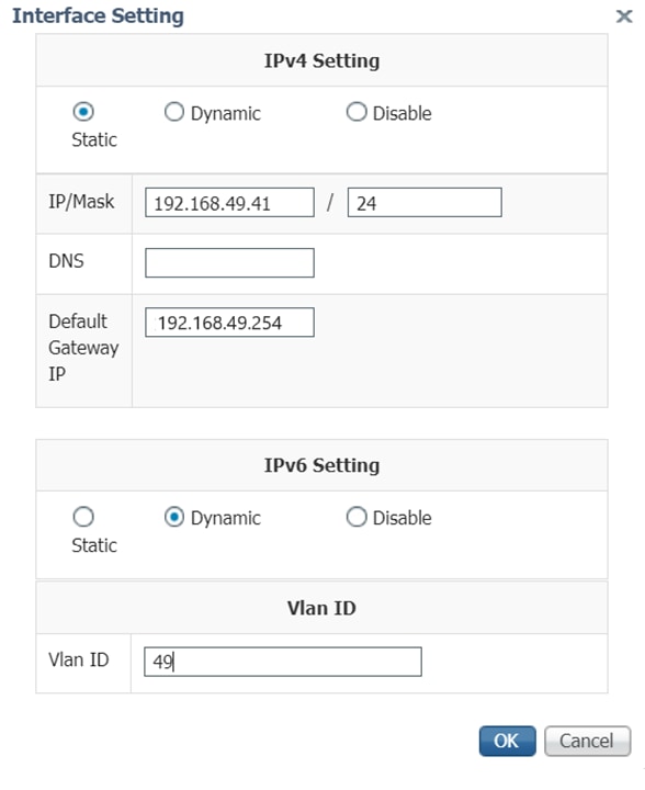
Fill the following parameters for the Collection interface:
|
|
Step 2 |
Click Next. |
|
Step 3 |
Active Discovery: If you want to enable Active Discovery on the sensor, select Passive and Active Discovery. You can:
|
|
Step 4 |
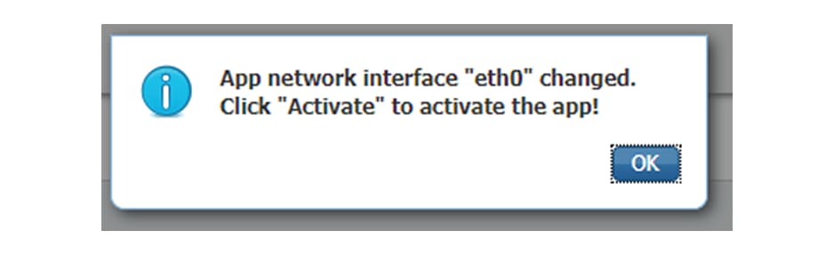
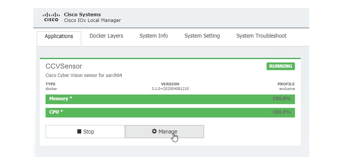
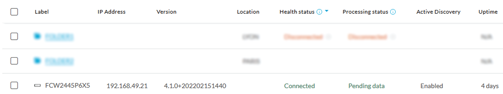
Click Deploy. The Center starts deploying the sensor application on the target equipment. This can take a few minutes. You can go to the Management jobs page to check the deployment advancements. 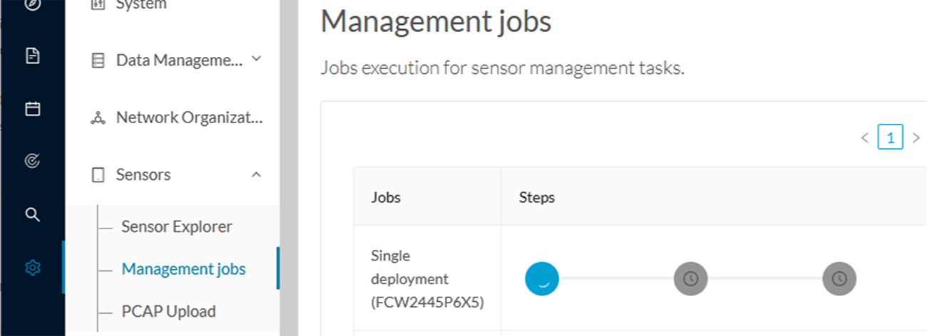 Once the deployment is finished, a new sensor appears in the sensors list. The sensor's status will eventually turn to connected.  If the Active Discovery has been enabled and set -that is if the option Passive and Active Discovery was selected when configuring the sensor in the sensor management extension- the sensor is displayed as below with Active Discovery's status as Enabled. 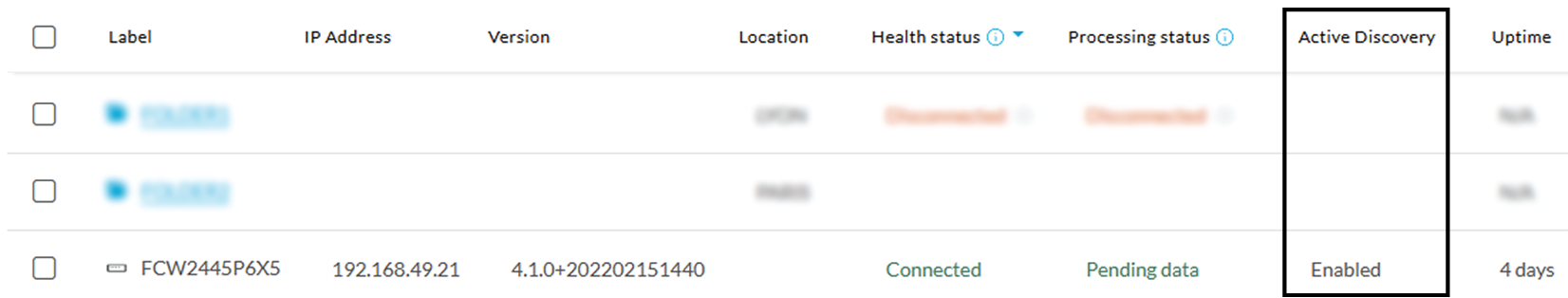 |
t_Center-Sensor on same Network_conf-sensor-mgmt-ext
Before you begin
Procedure
|
Step 1 |
|
|
Step 2 |
|
|
Step 3 |
What to do next
t_Platform-Sensor on different Network_conf-sensor-mgmt-ext
Before you begin
Procedure
|
Step 1 |
|
|
Step 2 |
|
|
Step 3 |
What to do next
t_Center-Sensor on different Network with L3nat-iox_conf-sensor-mgmt-ext
Before you begin
Procedure
|
Step 1 |
|
|
Step 2 |
|
|
Step 3 |
What to do next
Configure a sensor in the sensor management extension
If the Center can join the switch, the following form will appear.
Even if some parameters are filled automatically, you can change them if necessary or opt to modify recommended addresses based on the scheme shown in the previous section.
Center-sensor on same network
Before you begin
Procedure
|
Step 1 |
|
|
Step 2 |
|
|
Step 3 |
What to do next
Center-sensor on different network
Before you begin
Procedure
|
Step 1 |
|
|
Step 2 |
|
|
Step 3 |
What to do next
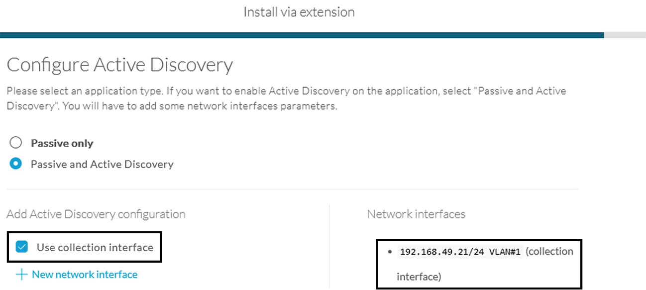
Configure Active Discovery
Once the sensor is connected, you can change the Active Discovery's network interface so it uses the Collection network interface instead, and add several network interfaces for the sensor to perform Active Discovery on several subnetworks at the same time.
Procedure
|
Step 1 |
Click the sensor to configure and click the Active Discovery button on its right side panel. 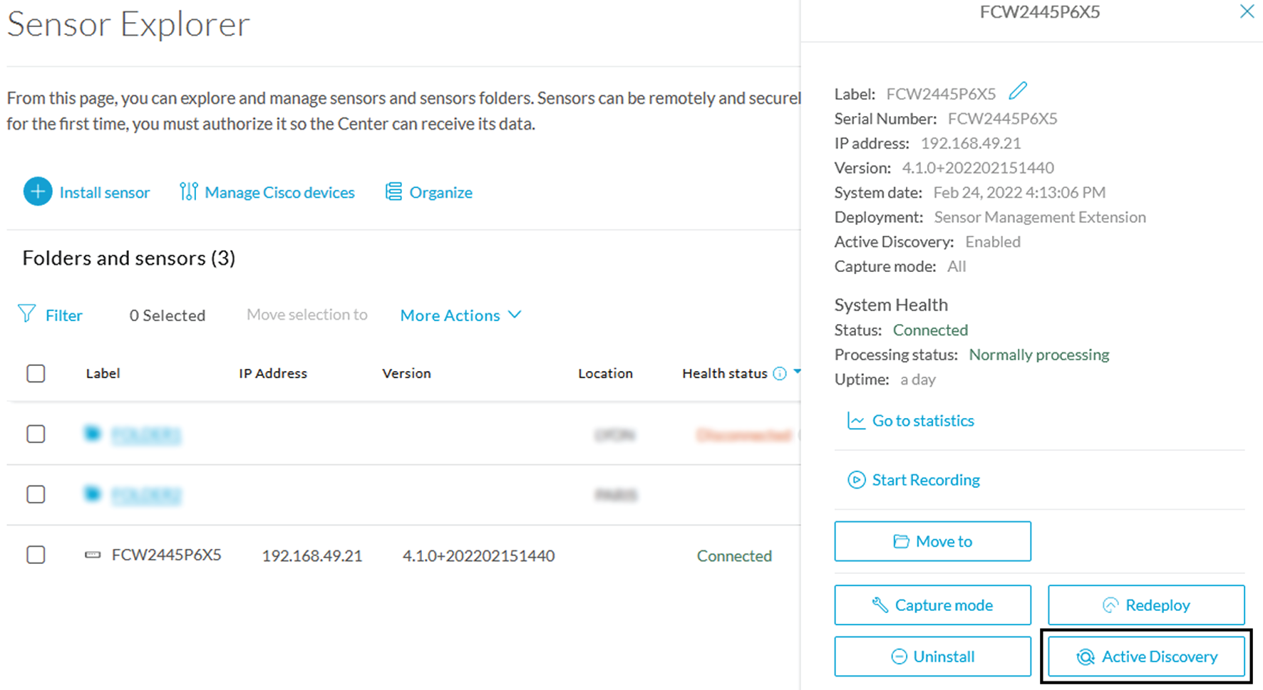 The Active Discovery configuration appears with the interface currently set. |
|
Step 2 |
Select Use collection interface for the Active Discovery to use the Collection network interface. 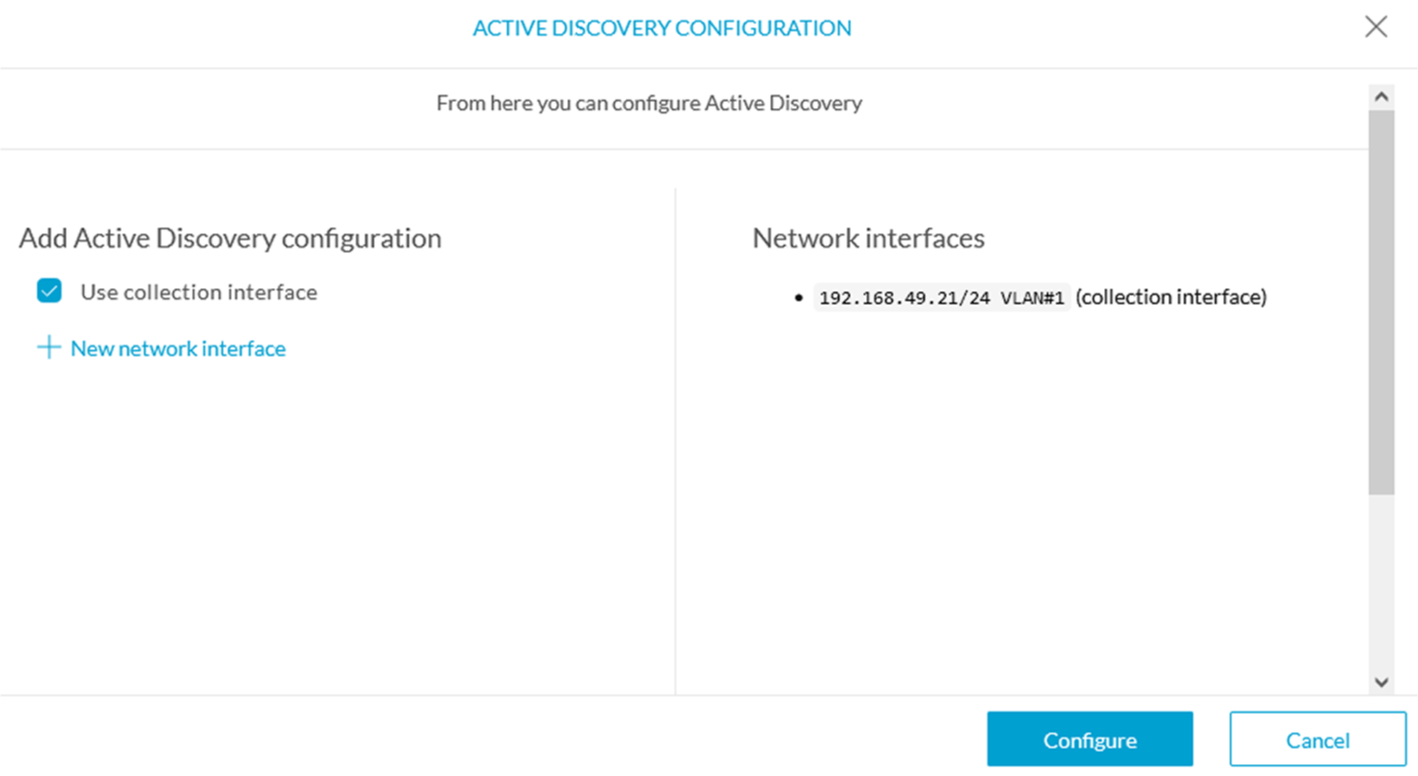 |
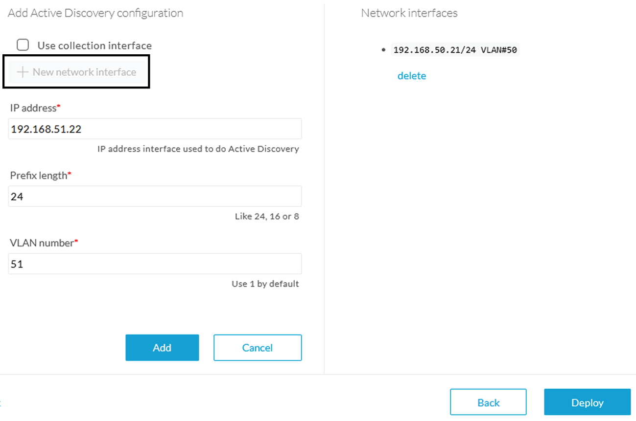
To add a network interface to Active Discovery for the sensor to perform active monitoring on another subnetwork:
|
Step 3 |
Add a new network interface by clicking the corresponding button. |
|
Step 4 |
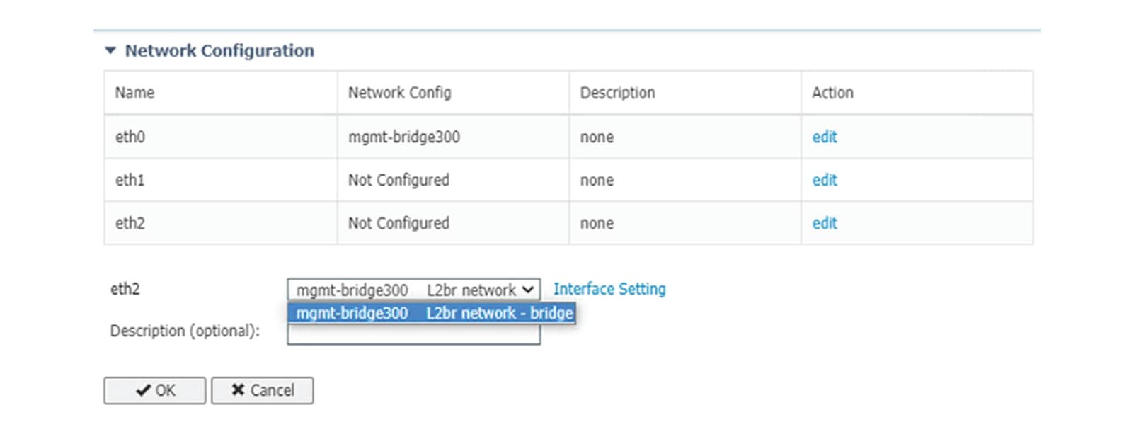
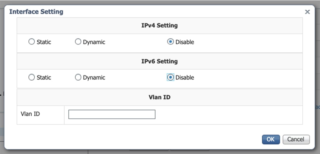
Fill the following parameters to set dedicated network interfaces:
|
|
Step 5 |
Click Add. 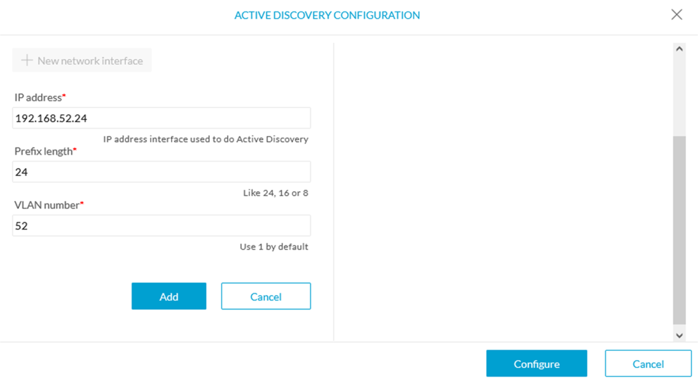 You can add as many network interfaces as needed. |
|
Step 6 |
When you are done, click Configure. A message saying that the configuration has been applied successfully appears. |


 Feedback