Features
The Cisco Content Security Management Appliances (SMA) M195, M395, M695, and M695F centralize reporting, tracking, management of quarantined email messages, and web security appliance configuration settings. They also allow automated data backups.
The SMA M195, M395, M695, and M695F support Cisco AsyncOS version 12.5 and later. See Product ID Numbers for a list of field-replaceable product IDs (PIDs) associated with the SMA security management appliances.
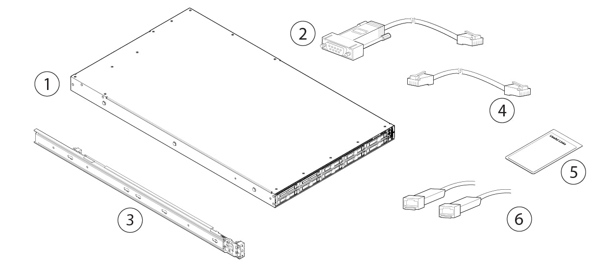
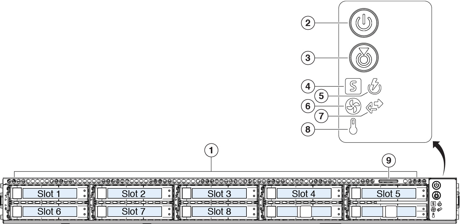
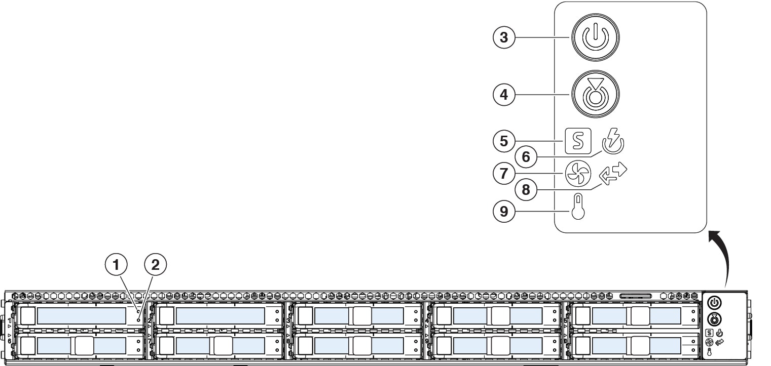
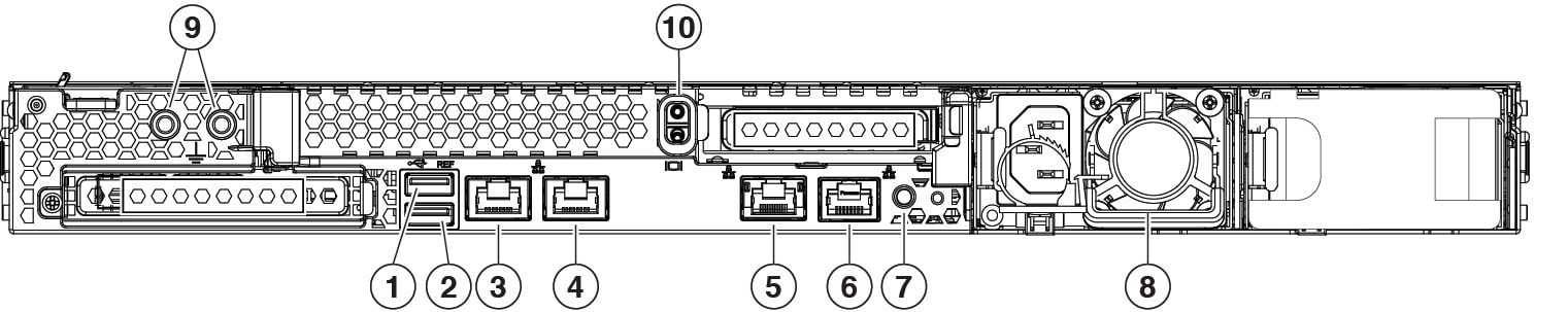
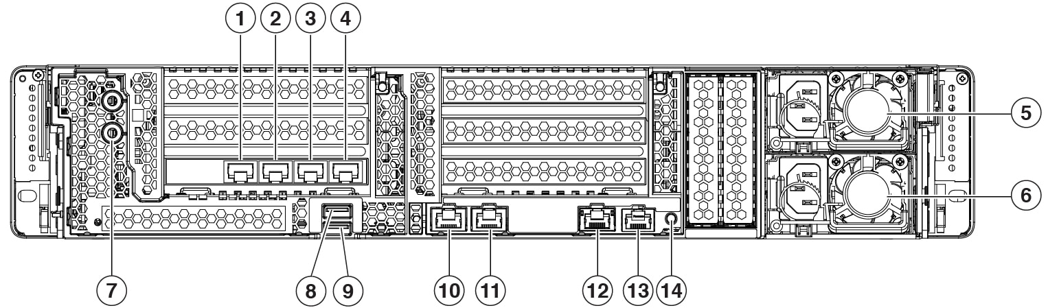
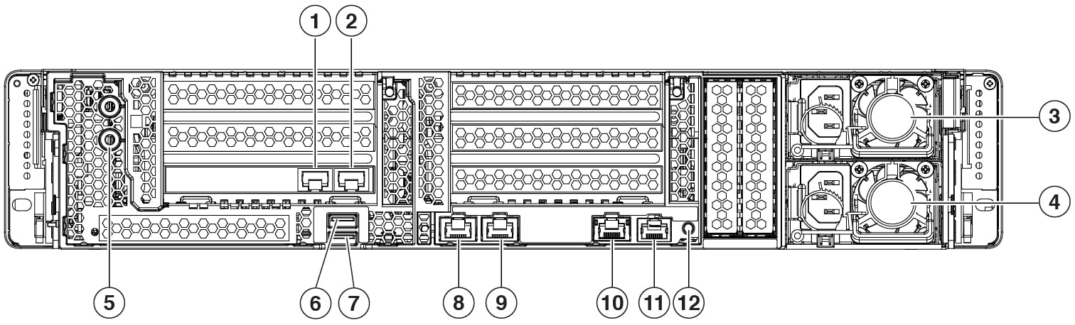
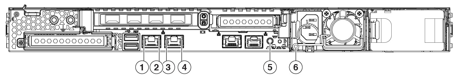
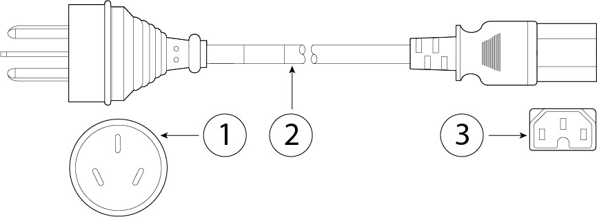
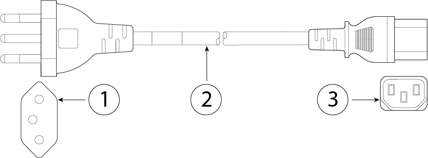
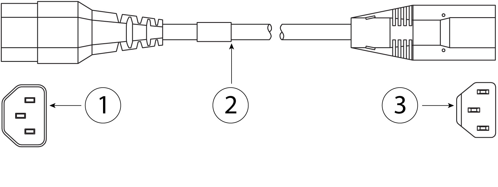
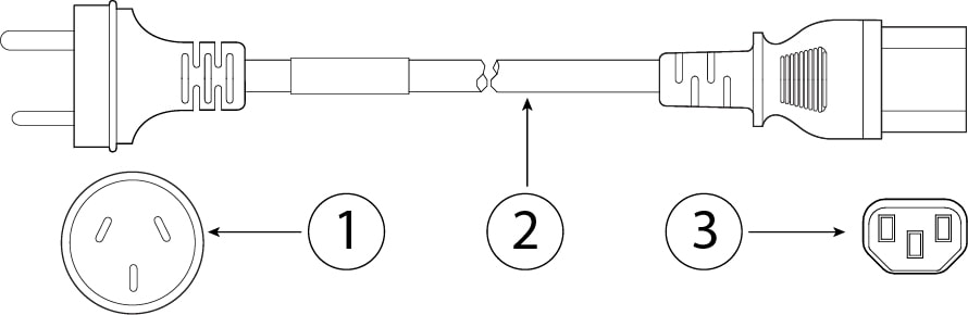
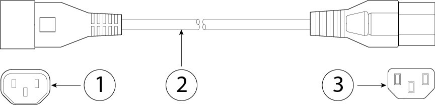
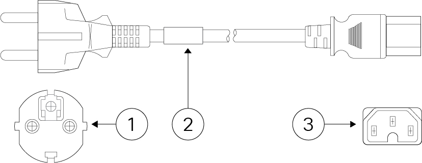
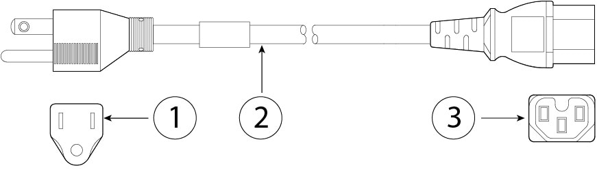
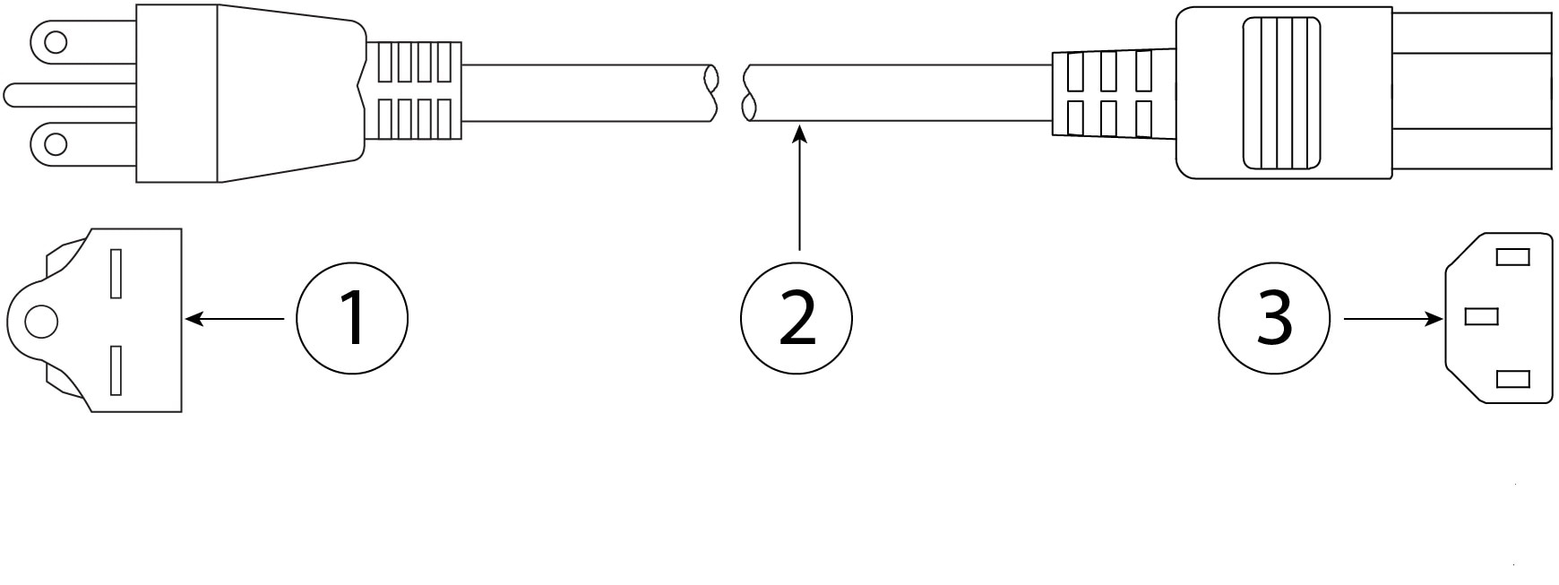
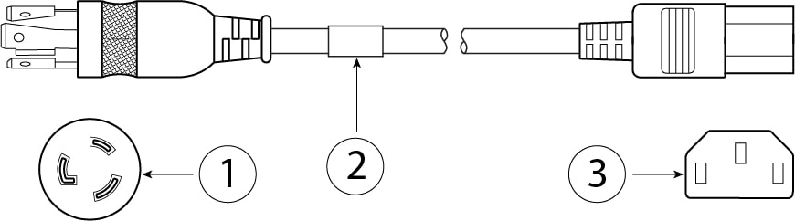
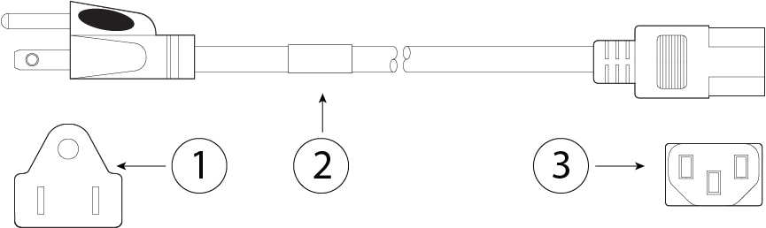
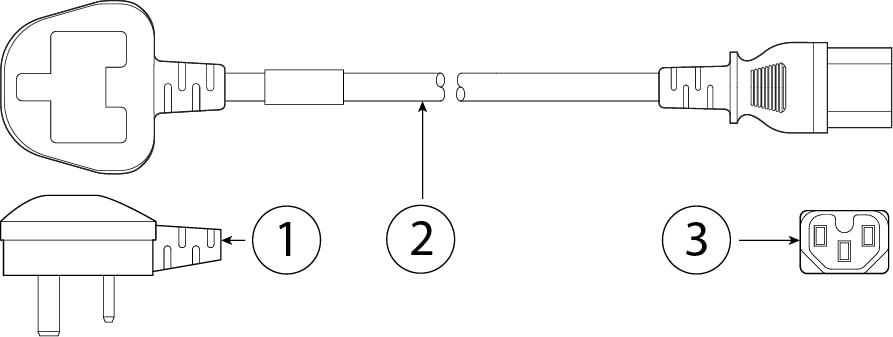
The following figures show the Cisco Content Security Appliances.


The following table lists the features of the SMA M195, M395, M695, and M695F.
|
Feature |
M195 |
M395 |
M695 |
M695F |
||
|---|---|---|---|---|---|---|
|
Form factor |
1 RU |
2 RU |
||||
|
Rack mount |
Standard 19-inch (48.3 cm) 4-post EIA rack |
|||||
|
Airflow |
Front to rear Cold aisle to hot aisle |
|||||
|
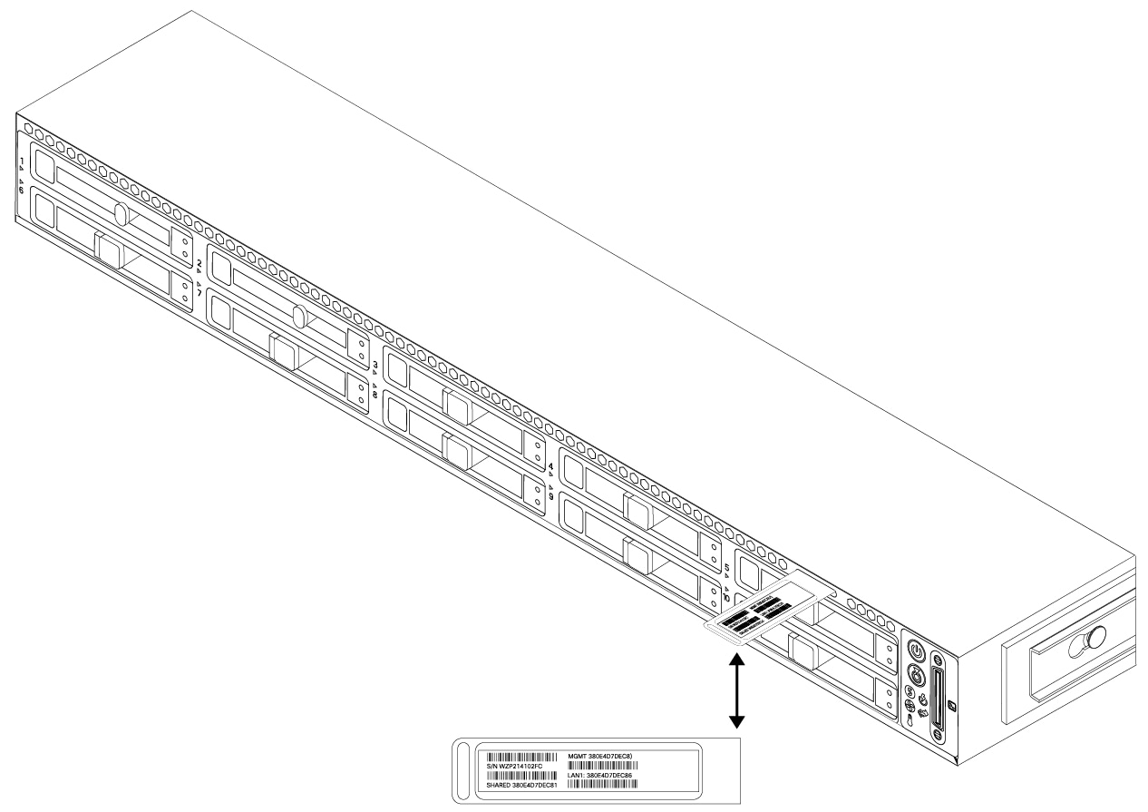
Pullout asset card |
Displays the serial number |
|||||
|
Grounding holes |
Two threaded holes for dual-hole grounding lug Use is optional; the supported AC power supplies have internal grounding, so no additional chassis grounding is required. |
|||||
|
Locking faceplate |
Optional |
|||||
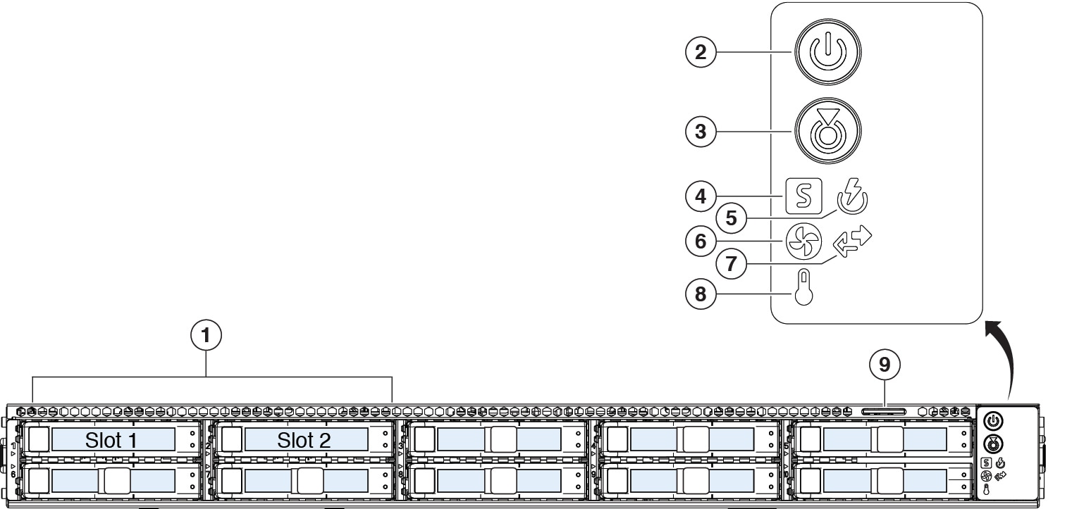
|
Unit identification button |
On front panel |
|||||
|
Power button |
On rear panel |
|||||
|
Processor |
Before January 2021: One Intel Xeon 4110 After January 2021: One Intel Xeon 4210 |
Before January 2021: One Intel Xeon 4116 After January 2021: One Intel Xeon 4216 |
Before January 2021: Two Intel Xeon 4110 After January 2021: Two Intel Xeon 4210 |
|||
|
Memory |
16-GB RAM |
32-GB RAM |
||||
|
RDIMMs Internal component only; not field-replaceable |
Before January 2021: One 16-GB DDR4-2400-MHz DIMM After January 2021: One 16-GB DDR4-2933-MHz DIMM |
Before January 2021: Two 16-GB DDR4-2400-MHz DIMMs After January 2021: Two 16-GB DDR4-2933-MHz DIMMs |
||||
|
Management port |
One built-in port (DATA 1) |
One built-in port (MGMT) |
||||
|
Network ports |
One Gigabit Ethernet (DATA 2) |
Five Gigabit Ethernet (DATA 1, DATA 2, DATA 3, DATA 4, DATA 5) |
One Gigabit Ethernet (DATA 1) Two fiber optic (DATA 2 and DATA 3) |
|||
|
Remote power cycling (RPC) |
Accessed through the 1-Gb dedicated port |
|||||
|
USB ports |
Two USB 3.0 Type A
|
|||||
|
SFP+ ports |
No |
Two fiber optic |
||||
|
Supported SFP+ |
— |
GLC-SX-MMD (1 Gb) (optional) SFP-10G-SR (10 Gb) (optional) |
||||
|
Serial console port |
One 1-Gb RJ-45 serial port running RS-232 (RS-232D TIA-561) Directly connects a computer to the chassis |
|||||
|
AC power supply
|
One 770-W AC You can order a second power supply for redundancy as 1+1. |
Two 770-W AC Hot-swappable and redundant as 1+1 |
Two 1050-W AC Hot-swappable and redundant as 1+1 |
|||
|
Fans |
Six fans for front-to-rear cooling Internal component only; not field-replaceable. If one fan fails, you must send your chassis for return material authorization (RMA). |
|||||
|
Storage |
Two 600-GB SAS HDDs RAID 1, hot-swappable |
Eight 600-GB SAS HDDs RAID 10, hot-swappable |
Sixteen 600-GB SAS HDDs RAID 10, hot-swappable |
|||


 Feedback