Maintenance and Upgrade

Power Button Shut Down

The chassis runs in two modes:

  • Main power mode—Power is supplied to all components and all operating systems can run.

  • Standby power mode—Power is supplied only to the service processor and certain components. You can safely remove power cords from the chassis in this mode.


Caution

After you shut down the chassis to standby power, electric current is still present in the chassis. To completely remove power as directed in some maintenance procedures, you must disconnect all power cords from all power supplies in the chassis.

You can shut down the chassis using the front panel Power button or software management.

Procedure


Step 1

Check the Power LED:

  • Amber—The chassis is already in standby mode and you can safely remove power.

  • Green—The chassis is in main power mode and you must shut it down before you can safely remove power.

Step 2

Perform a graceful shutdown or a hard shutdown:

Caution 
To avoid data loss or damage to your operating system, perform a graceful shutdown of the operating system.
  • Graceful shutdown—Press and release the Power button. The operating system performs a graceful shutdown and the chassis goes into standby mode. The power LED is amber.

  • Emergency shutdown—Press and hold the Power button for four seconds to force the main power off and immediately enter standby mode.

Step 3

If a maintenance procedure instructs you to completely remove power from the chassis, disconnect all power cords from the power supplies.


Enable RPC

You must enable and configure RPC before you can remotely reset chassis power.

Before you begin

  • Cable the RPC port directly to a secure network.

  • Open necessary ports through the firewall to make sure the chassis is accessible remotely.

  • RPC requires a unique IPv4 address for the RPC port. You must use the following procedure to configure the RPC port. You cannot configure it using the ipconfig command.

  • To cycle chassis power you must have a third-party tool that supports the Intelligent Platform Management Interface (IPMI) version 2.0.

Procedure


Step 1

Use SSH or the serial console port to access the CLI.

Step 2

Log in using an account with Administrator access.

Step 3

Enter the following commands:

remotepower
setup
Step 4

Follow the prompts to specify the following:

  • The dedicated IP address for the RPC port, netmask, and gateway.

  • The username and password required to execute the power-cycle command.

    These credentials are independent of other credentials used to access your appliance. Store this information for administrators who may need to set up RPC in the future.

Step 5

Enter commit to save your changes.

Step 6

Test your configuration to verify that you can remotely manage chassis power.


What to do next

Reset the Chassis Remotely

Reset the Chassis Remotely

If the chassis requires a hard reset, you can reboot the chassis remotely using a third-party IPMI tool.

Before you begin

  • You must enable RPC in advance. See Enable RPC for the procedure.

  • Only the following IPMI commands are supported. Refer to your IPMI tool documentation on how to use them.

    status, on, off, cycle, reset, diag, soft
  • Set up a utility that can manage devices using IPMI version 2.0.

Procedure


Step 1

Use IPMI to issue a supported power-cycling command to the IP address assign to the RPC port.

Note 

The RPC port must be configured with the required credentials. See Enable RPC for more information.

For example, issue the following command from a UNIX computer with IPMI support:

ipmitool -I lan -H ip-address -U remoteresetuser -P password chassis power reset
Step 2

Wait at least 11 minutes for the chassis to reboot.


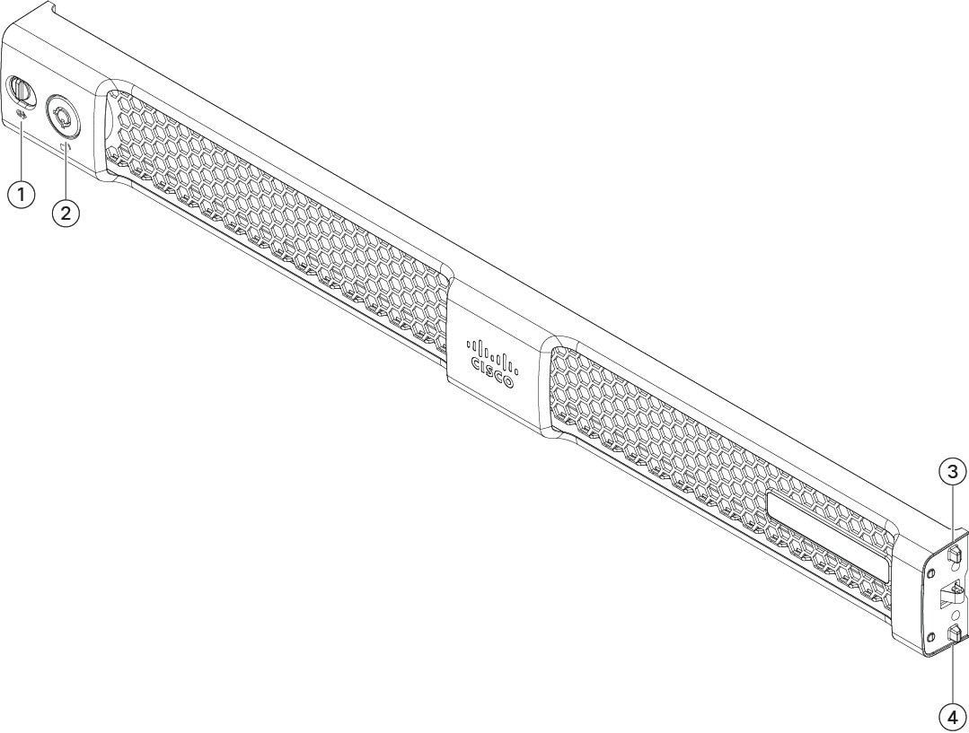
Install/Uninstall the Locking Faceplate

The locking faceplate (Cisco part number 74-115098-01 for a 1 RU chassis and Cisco part number 74-115099-01 for a 2 RU chassis) ships with the key you need to lock the faceplate to the front panel of the chassis. The locking faceplate clicks in between the two side handles on the front panel.

Procedure


Step 1

Insert the right side of the locking faceplate by aligning the two plastic tabs with the two cutouts on the right side handle on the front of the chassis.

Figure 1. Locking Faceplate

1

Latch

2

Key hole

3

Spring-mounted tab

4

Spring-mounted tab

Step 2

Press in the left side of the faceplate into the left side handle on the front panel. The tabs are spring-mounted to the latch, so they push in as the faceplate is installed.

Step 3

Lock the faceplate using the key that shipped with the faceplate.

Step 4

To uninstall the faceplate, unlock the faceplate, push the latch to the right, and pull the faceplate out.


Remove and Replace a Drive

The drives are hot-swappable. You do not have to shut down the chassis to remove or replace drives.

You cannot add more drives to the chassis. You can only replace the drives in the slots that are supported for your model.

Safety Warnings
Take note of the following warnings:

Warning

Statement 1018—Supply Circuit

To reduce risk of electric shock and fire, take care when connecting units to the supply circuit so that wiring is not overloaded.


Warning

Statement 1019—Main Disconnecting Device

The plug-socket combination must be accessible at all times, because it serves as the main disconnecting device.


Warning

Statement 1024—Ground Conductor

This equipment must be grounded. To reduce the risk of electric shock, never defeat the ground conductor or operate the equipment in the absence of a suitably installed ground conductor. Contact the appropriate electrical inspection authority or an electrician if you are uncertain that suitable grounding is available.


Warning

Statement 1030—Equipment Installation

Only trained and qualified personnel should be allowed to install, replace, or service this equipment.


Warning

Statement 1073—No User-Serviceable Parts

There are no serviceable parts inside. To avoid risk of electric shock, do not open.


Warning

Statement 1074—Comply with Local and National Electrical Codes

To reduce risk of electric shock or fire, installation of the equipment must comply with local and national electrical codes.


Procedure


Step 1

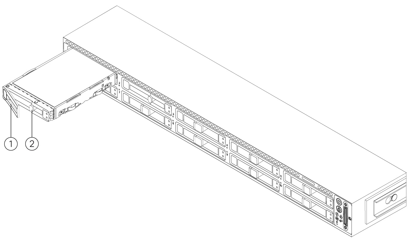
Remove the drive that you are replacing:

  1. Press the release button on the face of the drive tray.

  2. Grasp and open the ejector lever and then pull the drive tray out of the slot.

    Figure 2. Remove the Drive

    1

    Ejector handle

    2

    Release button

Step 2

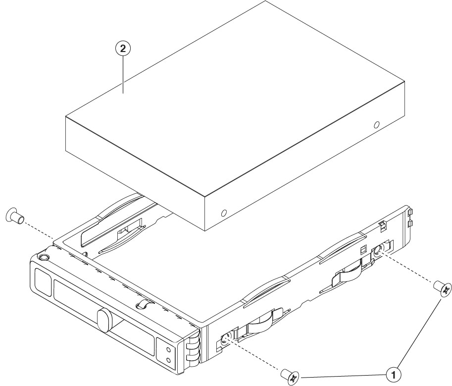
Remove the four drive-tray screws that secure the drive to the tray and then lift the drive out of the tray.

Figure 3. Remove the Drive Tray

1

Drive tray screws ( two on each side)

2

Drive removed from drive tray

Step 3

Install a new drive:

  1. Place a new drive in the empty drive tray and install the four drive-tray screws.

  2. With the ejector lever on the drive tray open, insert the drive tray into the empty drive bay.

  3. Push the tray into the slot until it touches the backplane, and then close the ejector lever to lock the drive in place.


Remove and Replace a Power Supply

Two power supplies ship with the chassis; they are redundant and hot-swappable. One is the active power supply and the other is the standby power supply (1+1).


Note

The C195 ships with one power supply, but you can add another one for redundancy.


The chassis also supports cold redundancy. Depending on the power being drawn by the chassis, one power supply might actively provide all power to the system while the remaining power supply is put into a standby state. For example, if the power consumption can be satisfied by power supply 1, then power supply 2 is put into a standby state.


Caution

When you replace power supplies, do not mix power supply types in the chassis. Both power supplies must be the same wattage and Cisco PID.


Trouble

Power supply health monitoring notifies you if the power supply loses power or malfunctions so that redundancy is lost. Check the power supply cables to make sure they are functioning. If they are and errors are still occurring, replace the power supply.


Safety Warnings
Take note of the following warnings:

Warning

Statement 1018—Supply Circuit

To reduce risk of electric shock and fire, take care when connecting units to the supply circuit so that wiring is not overloaded.


Warning

Statement 1019—Main Disconnecting Device

The plug-socket combination must be accessible at all times, because it serves as the main disconnecting device.


Warning

Statement 1024—Ground Conductor

This equipment must be grounded. To reduce the risk of electric shock, never defeat the ground conductor or operate the equipment in the absence of a suitably installed ground conductor. Contact the appropriate electrical inspection authority or an electrician if you are uncertain that suitable grounding is available.


Warning

Statement 1030—Equipment Installation

Only trained and qualified personnel should be allowed to install, replace, or service this equipment.


Warning

Statement 1073—No User-Serviceable Parts

There are no serviceable parts inside. To avoid risk of electric shock, do not open.


Warning

Statement 1074—Comply with Local and National Electrical Codes

To reduce risk of electric shock or fire, installation of the equipment must comply with local and national electrical codes.


Procedure


Step 1

Remove the power supply that you are replacing or the blank panel from an empty bay:

  1. Do one of the following actions:

    • If the chassis has one power supply, shut down and remove power from the chassis. See Power Button Shut Down for the procedure.

    • If the chassis has two power supplies, you do not have to shut down the chassis.

  2. Remove the power cord from the power supply that you are replacing.

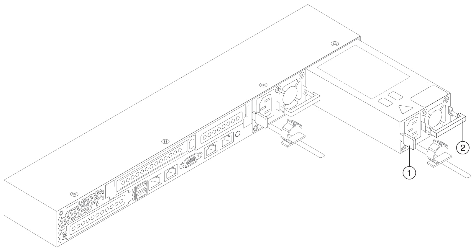
  3. Grasp the power supply handle while pinching the release lever toward the handle.

  4. Pull the power supply out of the bay.

Figure 4. Remove and Replace the AC Power Supply

1

Release lever

2

Handle

Step 2

Install a new power supply:

  1. Grasp the power supply handle and insert the new power supply into the empty bay.

  2. Push the power supply into the bay until the release lever locks.

  3. Connect the power cord to the new power supply.

  4. If you shut down the chassis, press the Power button to return it to main power mode.