Overview

About the ASA 5508-X and 5516-X

The Cisco ASA 5508-X and the ASA 5516-X adaptive security appliances are part of the ASA 5500-X of next-generation mid-range ASAs, and are built on the same security platform as the rest of the ASA family.


Note

Your ASA 5508-X and ASA 5516-X ship with either ASA or Firepower Threat Defense software preinstalled. To reimage your device, see Reimage the Cisco ASA or Firepower Threat Defense Device.


This next-generation ASA delivers unprecedented levels of defense against threats to the network with deeper web inspection and flow-specific analysis, improved secure connectivity via end-point security posture validation, and voice and video over VPN support. It also provides enhanced support for intelligent information networks through improved network integration, resiliency, and scalability.

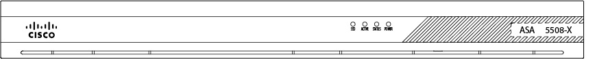
The ASA 5508-X and the ASA 5516-X are a standard 1 RU chassis. To compare the performance metrics and capabilities of the 5500-X ASAs, see Cisco ASA 5500-X Series Next-Generation Firewalls.

The ASA 5508-X and 5516-X have been validated for the following security standards certifications:

  • Federal Information Processing Standards (FIPS) 140-2 for FTD 6.4.x and ASA 9.12.x

  • Common Criteria (CC) certification for the Network Device Collaborative Protection Profile, (NDcPPv2.2E), VPN Gateway Module (VPNGW_MOD_v1.1), and Firewall Module (FW_MOD_v1.4e) for ASA 9.16.x

  • Common Criteria (CC) certification for the Network Device Collaborative Protection Profile, (NDcPPv2.2E), the IPS Extended Profile (IPSEP 2.11), Firewall Collaborative Protection Profile Module (MOD_FW_v1.4e), and Virtual Private Network Gateway Protection Profile Module (MOD_VPNGW_v1.1) for FTD 6.4.x


Note

Before beginning any of the procedures described in this book, be sure to read the Regulatory Compliance and Safety Information document and follow proper safety procedures.


Package Contents

The following figure shows the package contents for the ASA 5508-X and ASA 5516-X. Note that the contents are subject to change, and your exact contents might contain additional or fewer items.

Figure 1. ASA 5508-X and ASA 5516-X Package Contents

1

Chassis

2

USB console cable (Type A to Type B)

3

Power cord

4

Four 10-32-inch Phillips screws for rack mounting

5

Four 12-14-inch Phillips screws for rack mounting

6

Four M6 Phillip screws for rack mounting

7

Four M4 Phillips screws for rack mounting

Front Panel

The following figure shows the front panel of the ASA 5508-X. The ASA 5516 has an identical front panel. There are four LEDS on the front panel. See LEDs for the descriptions.

Figure 2. ASA 5508-X and ASA 5516-X Front Panel

Rear Panel

The following figure shows the rear panel of the Cisco ASA 5508-X and ASA 5516-X.

Figure 3. ASA 5508-X and ASA 5516-X Rear Panel

1

Power switch

Standard rocker-type power on/off switch

2

Power cord socket

The chassis power-supply socket. See Power Supply Modules for more information about the ASA power supply.

3

Status LEDs

The locations and meanings of the status LEDs are described in LEDs.

4

Network data ports

Eight Gigabit Ethernet RJ-45 (8P8C) network I/O interfaces. The ports are numbered (from left to right) 1, 2, 3, 4, 5, 6, 7, 8. Each port includes a pair of LEDs, one each for connection status and link status. The ports are named and numbered Gigabit Ethernet 1/1 through Gigabit Ethernet 1/8. See Network Ports for additional information.

5

Management port

A Gigabit Ethernet interface restricted to network management access only. Connect with an RJ-45 cable.

6

Console ports

Two serial ports, a mini USB Type B, and a standard RJ-45 (8P8C), are provided for management access via an external system. See Console Ports for additional information.

7

USB port

A standard USB Type A port is provided, allowing attachment of an external device such as mass storage. See Internal and External Flash Storage for additional information.

8

Reset button

A small recessed button that if pressed for longer than three seconds resets the ASA to its default “as-shipped” state following the next reboot. Configuration variables are reset to factory default. However, the flash is not erased, and no files are removed.

Note 

You can use the service sw-reset-button to disable the reset button. The default is enabled.

9

SSD LED

Status light for installed solid-state drive (SSD). See LEDs and Solid State Drive for more information.

10

SSD bay

Covered slot in which the SSD is installed. You can replace this drive if it fails. See Remove and Replace the SSD for more information.

LEDs

The LEDs are located just off center on the front panel, and just to the left of the network ports on the rear panel, with the SSD LED to the right of the Reset port. See Rear Panel for the locations.

LED

Description

Power

Power supply status:

  • Unlit—Power supply off.

  • Green—Power supply on.

See Power Supply Modules for additional power information.

Status

System operating status:

  • Green—Normal system function.

  • Amber—Critical alarm indicating one or more of the following:

    • Major failure of a hardware or software component.

    • Over-temperature condition.

    • Power voltage outside the tolerance range.

Active

Status of the failover pair:

  • Green—Failover pair operating normally.

  • Unlit—Failover is not operational.

Status of a high-availability (HA) pair:

  • Green—The active-mode unit.

  • Amber—The standby unit.

Role of a standalone device:

  • Green —The device is active normally.

SSD

SSD LED behavior at first customer ship:

  • Unlit—No SSD present.

  • Green—SSD installed.

SSD LED behavior after June 2017:

  • Unlit—No SSD present or no activity on the SSD.

  • Green—Activity on the SSD.

Note 

See Remove and Replace the SSD for information on replacing a failed SSD.

Network Port Status

On the rear panel, a pair of LEDs (Link status and Connection status) for each of the eight Gigabit Ethernet network ports, and the Gigabit Ethernet Management port.

Link status (L):

  • Unlit—No link, or port is not in use.

  • Green—Link established.

  • Green, flashing—Link activity.

Connection-speed status (S):

  • One blink every three seconds—10 Mbps.

  • Two rapid blinks—100 Mbps.

  • Three rapid blinks—1000 Mbps.

Network Ports

Looking at the rear of the ASA, where the ports are located, port 1 is on the left, and port 8 is on the right, next to the console and management ports. Each port is accompanied by a pair of LEDs, one each for link status (L) and connection status (S). The ports are named and numbered Gigabit Ethernet 1/1 through Gigabit Ethernet 1/8. The ports are named and numbered Gigabit Ethernet 1/1 through Gigabit Ethernet 1/4.

Console Ports

The ASA has two external console ports, a standard RJ-45 port and a Mini USB Type B serial port. Only one console port can be active at a time. When a cable is plugged into the USB console port, the RJ-45 port becomes inactive. Conversely, when the USB cable is removed from the USB port, the RJ-45 port becomes active. The console ports do not have any hardware flow control. You can use the command-line interface (CLI) to configure your ASA through either serial console port by using a terminal server or a terminal emulation program on a computer.

RJ-45 Port

The RJ-45 (8P8C) port supports RS-232 signaling to an internal UART controller. The RJ-45 console port does not support a remote dial-in modem. You can use a standard management cable (Cisco part number 72-3383-01) to convert the RJ45-to-DB9 connection if necessary.

Mini USB Type B Port

The Mini USB Type B port lets you connect to a USB port on an external computer. For Linux and Macintosh systems, no special driver is required. For Windows systems, you must download and install a USB driver (available on software.cisco.com). You can plug and unplug the USB cable from the console port without affecting Windows HyperTerminal operations. We recommend shielded USB cables with properly terminated shields. Baud rates for the USB console port are 1200, 2400, 4800, 9600, 19200, 38400, 57600, and 115200 bps.


Note

For Windows operating systems, you must install a Cisco Windows USB Console Driver on any PC connected to the console port before using the USB console port. See Connect to the Console Port with Microsoft Windows for information on installing the driver.


Internal and External Flash Storage

The ASA contains one internal USB flash drive, and a standard USB Type A port that you can use to attach an external device. The USB port can provide output power of 5 volts, up to a maximum of 500 mA (5 USB power units).

Internal USB Device

An embedded eUSB device is used as the internal flash; it is identified as disk0.

External USB Drive (Optional)

You can use the external Type A USB port to attach a data-storage device. The external USB drive identifier is disk1. When the ASA is powered on, a connected USB drive is mounted as disk1 and is available for you to use. Additionally, the file-system commands that are available to disk0 are also available to disk1, including copy, format, delete, mkdir, pwd, cd, and so on.

If you insert a USB drive with more than one partition, only the first partition is mounted.

FAT-32 File System

The ASA only supports FAT-32-formatted file systems for the internal eUSB and external USB drives. If you insert an external USB drive that is not in FAT-32 format, the system mounting process fails, and you receive an error message. You can enter the command format disk1: to format the partition to FAT-32 and mount the partition to disk1 again; however, data might be lost.

Solid State Drive

The ASA 5508-X and 5516-X ship with an SSD installed that provides storage support. The SSD in the ASA 5508-X has 80 GB of useable space and is field-replaceable. The SSD in the ASA 5516-X has 1000 GB of usable space and is also field replaceable. See Remove and Replace the SSD for information about replacing it.

Power Supply Modules

The ASA 5508-X and ASA 5516-X ship with an internal 100-240 V AC power supply that provides 60 W.

Hardware Specifications

The following table contains hardware specifications for the ASA 5508-X and the ASA 5516-X.

Table 1. Hardware Specifications

Physical Specifications

Form factor

1 RU

Rack mountable

Side-mount “ear” brackets included. See Rack-Mount the Chassis for more information.

Wall mountable

No.

Dimensions

17.2 x 11.288 x 1.72 in. (43.688 x 28.672 x 4.369 cm)

Weight

8 lb

Memory

DRAM

Total: 8 GB

Allocated to FW/VPN: 4 GB

Allocated to Module: 4 GB

Internal Flash

8 GB

Power

60 W

Environment

Temperature

Operating: 0 to 40°C (32 to 104°F)

Nonoperating: -25 to 70°C (-13 to 158°F)

Relative humidity

Operating: 90%

Nonoperating: 10 to 90%

Maximum altitude

Operating: 3048 m (10,000 ft)

Nonoperating: 4572 m (15,000 ft)

Acoustic Noise

Typical: 41.6 dBA

Maximum: 67.2 dBA

Power Cord Specifications

Each power supply has a separate power cord. Standard power cords are available for connection to the security appliance.

If you do not order the optional power cord with the system, you are responsible for selecting the appropriate power cord for the product. Using a incompatible power cord with this product may result in electrical safety hazard. Orders delivered to Argentina, Brazil, and Japan must have the appropriate power cord ordered with the system.


Note

Only the approved power cords provided with the security appliance are supported. The following table lists the supported power cords.


The following illustrations show the cord, connector, and plug for each country listed in the table above.

Figure 4. Argentina (CAB-ACR)

1

Plug: IRAM 2073

2

Cord set rating: 10 A, 250 V

3

Connector: IEC 60320/C13

Figure 5. Australia (CAB-ACA)

1

Plug: A.S. 3112

2

Cord set rating: 10 A, 250 V

3

Connector: IEC 60320/C13

Figure 6. Brazil (CAB-C13-ACB)


1

Plug: NBR 14136

2

Cord set rating: 10 A, 250 V

3

Connector: IEC 60320/C13

Figure 7. China (CAB-ACC)

1

Plug: GB2009.1-2008

2

Cord set rating: 10 A, 250 V

3

Connector: IEC 60320/C13

Figure 8. Europe (CAB-ACE)

1

Plug: CEE 7 VII

2

Cord set rating: 10 A, 250 V

3

Connector: IEC 60320/C13

Figure 9. India (CAB-IND-10A)


1

Plug: IS 6538-1971

2

Cord set rating: 10 A, 250 V

3

Connector: IEC 60320/C13

Figure 10. Italy (CAB-ACI)

1

Plug: CE123-16-VII

2

Cord set rating: 10 A, 250 V

3

Connector: IEC 60320/C13

Figure 11. Japan (CAB-JPN-3PIN)

1

Plug: JIS C8303

2

Cord set rating: 12 A, 125 V

3

Connector: IEC 60320/C13

Figure 12. Korea (CAB-AC-C13-KOR)

1

Plug: KSC8305

2

Cord set rating: 10 A, 250 V

3

Connector: IEC 60320/C13

Figure 13. North America (CAB-AC)

1

Plug: NEMA 5-15P

2

Cord set rating: 10 A, 125 V

3

Connector: IEC 60320/C13

Figure 14. South Africa (AIR-PWR-CORD-SA)

1

Plug: SABS 1661

2

Cord set rating: 10 A, 250 V

3

Connector: IEC 60320/C13

Figure 15. Switzerland (CAB-ACS)

1

Plug: SEV 1011

2

Cord set rating: 10 A, 250 V

3

Connector: IEC 60320/C13

Figure 16. Taiwan (CAB-ACTW)

1

Plug: CNS10917

2

Cord set rating: 10 A, 250 V

3

Connector: IEC 60320/C13

Figure 17. United Kingdom (CAB-ACU)


1

Plug: BS1363a/SS145

2

Cord set rating: 10 A, 250 V

3

Connector: IEC 60320/C13