Overview

Features

The Cisco AMP PC3000 appliance supports AMP Private Cloud version 3.0 and later.

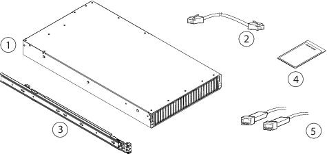
The following table lists the features of the Cisco AMP PC3000. See Product ID Numbers for a list of the spare product IDs (PIDs) associated with the AMP PC3000. You can remove and replace drives and power supplies. For all other internal component failures, you must send your chassis for RMA.

Table 1. AMP PC3000

Feature

Description

Form factor

2 RU

Rack mount

Yes

Standard 19-in. (48.3 cm) 4-post EIA rack

Airflow

Front to rear

Cold aisle to hot aisle
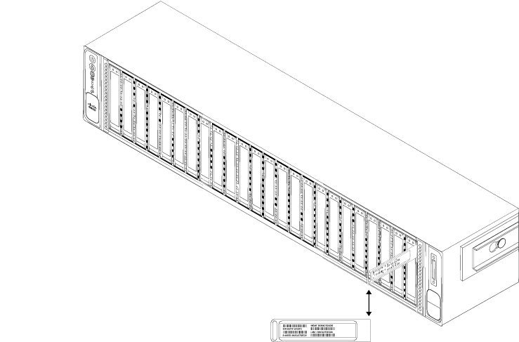
Pullout asset card

Displays the serial number.

Grounding hole

Yes

Two threaded holes for dual-hole grounding lug.

Use is optional. The supported AC power supplies have internal grounding, so no additional chassis grounding is required.
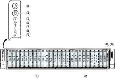
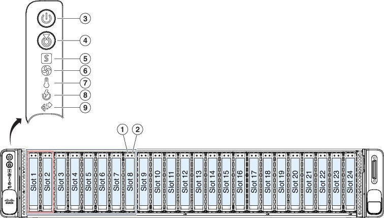
Locator beacon

Yes

Power switch

Yes

Processor

Before January 2021: Two Intel Xeon Gold 6126 processors

After January 2021: Two Intel Xeon Gold 6226 processors

Memory

1.5 TB RAM

RDIMMs

Before January 2021: Twenty-four 64-GB DDR4-2666-MHz RDIMMs

After January 2021: Twenty-four 64-GB DDR4-2933-MHz RDIMMs
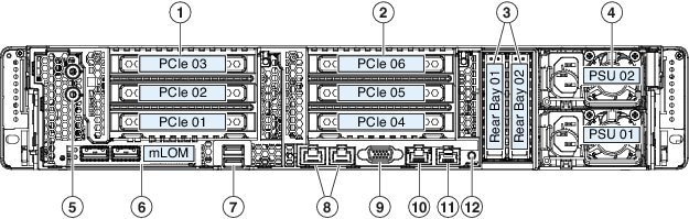
Management ports

Two built-in dual 1/10-GB ports

USB ports

2

Version 3.0 Type A

VGA port

One 3-row 15-pin DE-15 connector

Enabled by default.

SFP ports

4 fixed SFP+ ports

Supported SFP cables SFP-10G-SR

Serial console port

One 1-GB RJ45 serial port running RS-232 (RS-232D TIA-561)

System power

Two 1050-W AC power supplies (hot-swappable and redundant as 1+1)

Power consumption

3196 BTU/hr

Fans

6 fans for front-to-rear cooling

Storage

Fourteen 800-GB SSDs RAID 6

Ten 1.8-TB SAS HDDs RAID 6

Two 1.2-TB SAS HDDs RAID 1

Hot-swappable

RAID controller

1

Package Contents

The following figure shows the package contents for the AMP PC3000. Note that the contents are subject to change and your exact contents might contain additional or fewer items.

Figure 1. Package Contents

1

Chassis

2

RJ-45 to RJ-45 Cat 5 Ethernet cable, yellow six feet long (Cisco part number 72-1482-XX)

3

Cisco rail kit (Cisco part number 800-43376-02)

4

Useful Links printed document

The steps in the Useful Links document send you to the documentation you need to install, set up, and configure your AMP PC3000.

5

SFP+ cables (Optional; in package if ordered.)

Serial Number Location

The serial number (SN) for the AMP PC3000 is printed on the pullout asset card located on the front panel as shown in the following figure.

Figure 2. Serial Number on Pullout Asset Card

The serial number is also on the label on the cover of the chassis as shown in the following figure.


Caution

The cover latch on the top of the chassis cover is not supported. There are no internal field-replaceable parts in the AMP PC3000.


Figure 3. Serial Number Location on Cover

1

Serial number label

Front Panel

The following figure shows the front panel features and disk-drive configuration for the AMP PC3000. See Front Panel LEDs for a description of the LEDs.

Figure 4. AMP PC3000 Front Panel

1

Drive bays 1-14 are populated with SSDs for the /data volume.

2

Drive bays 15-24 populated with SAS HDDs for the /other volume.

3

Power button/power status LED

4

Unit identification button/LED

5

System status LED

6

Fan status LED

7

Temperature status LED

8

Power supply status LED

9

Network link activity LED

10

Pullout asset card

11

KVM connector

Used with KVM cable that provides one DB-15 VGA, one DB-9 serial, and two USB connectors.

-

Front Panel LEDs

The following figure shows the front panel LEDs and describes their states.

Figure 5. Front Panel LEDs and Their States

1

SAS/SATA drive fault

  • Off—The drive is operating properly.

  • Amber—Drive fault detected.

  • Amber, flashing—The drive is rebuilding.

  • Amber, flashing with one-second interval—Drive locate function activated in the software.

2

SAS/SATA drive activity LED

  • Off—There is no drive in the drive tray (no access, no fault).

  • Green—The drive is ready.

  • Green, flashing—The drive is reading or writing data.

3

Power button/LED

  • Off—There is no AC power to the appliance.

  • Amber—The appliance is in standby mode.

  • Green—The appliance is in main power mode. Power is supplied to all appliance components.

4

Unit identification

  • Off—The unit identification function is not in use.

  • Blue, flashing—The unit identification function is activated.

5

System health

  • Green—The appliance is running in normal operating condition.

  • Green, flashing—The appliance is performing system initialization and memory check.

  • Amber—The appliance is in a degraded operational state (minor fault). For example:

    • Power supply redundancy is lost.

    • CPUs are mismatched.

    • At least one CPU is faulty.

    • At least one DIMM is faulty.

    • At least one drive in a RAID configuration failed.

  • Amber, 2 flashes—There is a major fault with the system board.

  • Amber, 3 flashes—There is a major fault with the memory DIMMs.

  • Amber, 4 flashes—There is a major fault with the CPUs.

6

Power supply status

  • Green—All power supplies are operating normally.

  • Amber—One or more power supplies are in a degraded operational state.

  • Amber, flashing—One or more power supplies are in a critical fault state.

7

Fan status

  • Green—All fan modules are operating properly.

  • Amber, flashing—One or more fan modules breached the unrecoverable threshold.

8

Network link activity

  • Off—The Ethernet Lights Out Management (LOM) port link is idle.

  • Green—One or more Ethernet LOM ports are link-active, but there is no activity.

  • Green, flashing—One or more Ethernet LOM ports are link-active, with activity.

9

Temperature status

  • Green—The appliance is operating at normal temperature.

  • Amber—One or more temperature sensors breached the critical threshold.

  • Amber, flashing—One or more temperature sensors breached the unrecoverable threshold.

Rear Panel

The following figure shows the rear panel of the AMP PC3000.

Figure 6. Rear Panel

1

PCIe riser 1 (PCIe slot 1, 2, 3)

PCIe slot 3 is used for the SFP+ ports. PCIe slots 1 and 2 are not supported.

2

PCIe riser 2 (PCIe slots 4, 5, 6)

PCIe riser 2 is not supported.

3

2.5-inch HDD bays containing 1.2-TB SAS HDDs for the recovery partition

4

Power supplies (two, redundant as 1+1)

5

Threaded holes for dual-hole grounding lug

6

Modular LAN-on-motherboard (mLOM) card slot (x16)

7

2 USB 3.0 Type A ports

8

Dual 1-Gb/10-Gb Ethernet ports (LAN1 and LAN2)

The dual LAN ports can support 1 Gbps and 10 Gbps depending on the link partner capability.

9

VGA video port (DB-15 connector)

10

1-Gb Ethernet dedicated Cisco Integrated Management Controller (CIMC) port

11

Serial port (RJ-45 connector)

12

Rear unit identification button/LED

Rear Panel LEDs

The following figure shows the rear panel LEDs and describes their states.

Figure 7. Rear Panel LEDs and Their States

1

1-Gb/10-Gb Ethernet link speed (on both LAN1 and LAN2)

  • Amber—Link speed is 100 Mbps

  • Amber—Link speed is 1 Gbps

  • Green—Link speed is 10 Gbps

2

1-Gb/10-Gb Ethernet link status (on both LAN1 and LAN2)

  • Off—No link is present

  • Green—Link is active

  • Green, flashing—Traffic is present on the active link

3

1-Gb Ethernet dedicated management link speed

  • Off—Link speed is 10 Mbps

  • Amber—Link speed is 100 Mbps

  • Green—Link speed is 1 Gbps

4

1-Gb Ethernet dedicated management link status

  • Off—No link is present

  • Green—Link is active

  • Green, flashing—Traffic is present on the active link

5

Rear unit identification

  • Off—The unit identification function is not in use

  • Blue, flashing—The unit identification function is activated

6

Power supply status (one LED for each power supply unit)

  • Off—No AC input (12 V main power off, 12 V standby power off)

  • Green, flashing—12 V main power off; 12 V standby power on

  • Green—12 V main power on; 12 V standby power on

  • Amber, flashing—Warning threshold detected but 12 V main power on

  • Amber—Critical error detected; 12 V main power off (for example, over-current, over-voltage, or over-temperature failure)

7

SAS/SATA drive fault

  • Off—The drive is operating properly

  • Amber—Drive fault detected

  • Amber, flashing—The drive is rebuilding

  • Amber, flashing with one-second interval—Drive locate function activated in the software

8

SAS/SATA drive activity LED

  • Off—There is no drive in the drive tray (no access, no fault)

  • Green—The drive is ready

  • Green, flashing—The drive is reading or writing data

Power Supply

The following table lists the specifications for each 1050-W AC power supply (Cisco part number UCSC-PSU1-1050W) used in the AMP PC3000.

Table 2. Power Supply Specifications

Description

Specification

Power consumption

1313 BTU/hr

AC input voltage range

Nominal range: 100 to 120 V AC, 200 to 240 V AC

Range: 90–132 V AC, 180–264 V AC

AC input frequency

Nominal range: 50–60 Hz

Range: 47–63 Hz

Maximum AC input current

12.5 A peak at 100 V AC

6.0 A peak at 208 V AC

Maximum input volt amperes

1250 VA at 100 V AC

Maximum output power for each power supply

1050 W

Maximum inrush current

15 A (subcycle duration)

Maximum hold-up time

12 ms at 1050 W

Power supply output voltage

12 V DC

Power supply standby voltage

12 V DC

Efficiency rating

Climate Savers Platinum Efficiency (80 Plus Platinum certified)

Form factor

RSP2

Input connector

IEC320 C14

Hardware Specifications

The following table lists the hardware specifications for the AMP PC3000.

Table 3. AMP PC3000 Hardware Specifications

Specification

Dimensions (H x W x D)

3.4 x 16.9 x 29.5 in. (8.64 x 42.9 x 74.0 cm)

Maximum weight (fully loaded chassis)

57.5 lb (26.1 kg)

Temperature

Operating: 50 to 95°F (10 to 35°C)

Maximum temperature is derated by 1°F/547 ft (1°C/300 m) of altitude above 3117 ft (950 m).

Nonoperating: –40 to 149°F (–40 to 65°C) when the appliance is stored or transported.

Relative humidity

Operating: 8 to 90% noncondensing

Nonoperating: 5 to 95% noncondensing

Altitude

Operating: 0 to 10,000 ft

Nonoperating: 0 to 40,000 ft when the appliance is stored or transported

Sound power level

5.8 Bels (measure A-weighted per ISO7779 LWAd)

Operation at 73°F (23°C)

Sound pressure level

43 dBa (measure A-weighted per ISO7779 LpAM)

Operation at 73°F (23°C)

Product ID Numbers

The following table lists the spare Product IDs (PIDs) associated with the AMP PC3000. The spare components are ones that you can order and replace yourself. If any internal components fail, you must RMA the entire chassis including the SFPs and SFP cables. Remove the drives and power supplies before you send the chassis for RMA. You can view an inventory of PIDs using the Cisco Integrated Management Interface (CIMC). See Viewing Product ID (PID) Catalog Details for more information.

Table 4. AMP PC3000 PIDs

PID

Description

AMPPC-AC-1050

Power supply

AMPPC-AC-1050=

Power supply (spare)

AMPPC-HDD-1.2TB

1.2-TB hard disk drive

AMPPC-HDD-1.2TB=

1.2-TB hard disk drive (spare)

AMPPC-HDD-1.8TB

1.8-TB hard disk drive

AMPPC-HDD-1.8TB=

1.8-TB hard disk drive (spare)

AMP-S800GK3X-EP

800-GB solid state drive

AMP-S800GK3X-EP=

800-GB solid state drive (spare)

UCSC-RAILB-M4

Rail kit

UCSC-RAILB-M4=

Rail kit (spare)

Power Cord Specifications

If you do not order the optional power cord with the system, you are responsible for selecting the appropriate power cord for the product. Using a incompatible power cord with this product may result in electrical safety hazard. Orders delivered to Argentina, Brazil, and Japan must have the appropriate power cord ordered with the system.

The following power cords and jumper cords are supported.

Figure 8. Argentina CAB-250V-10A-AR

1

Plug: IRAM 2073

2

Cord set rating: 10 A, 250 V

3

Connector: IEC 60320/C13

Figure 9. Australia CAB-9K10A-AU

1

Plug: A.S. 3112-2000

2

Cord set rating: 10 A, 250 V

3

Connector: IEC 60320/C15

Figure 10. Brazil PWR-250V-10A-BZ

1

Plug: NBR 14136

2

Cord set rating: 10 A, 250 V

3

Connector: IEC 60320/C13

Figure 11. Cabinet Jumper CAB-C13-C14-2M

1

Plug: SS10A

2

Cord set rating: 10A, 250V

3

Connector: HS10S, C-13 to C-14

Figure 12. Cabinet Jumper CAB-C13-C14-AC

1

Plug: SS10A

2

Cord set rating: 10 A, 250 V

3

Connector: HS10S, C-13 to C-14 (recessed receptacle)

Figure 13. Cabinet Jumper CAB-C13-CBN

1

Plug: SS10A

2

Cord set rating: 10 A, 250 V

3

Connector: HS10S, C-13 to C-14

Figure 14. China CAB-250V-10A-CH

1

Plug: GB2099.1/2008

2

Cord set rating: 10 A, 250 V

3

Connector: IEC 60320/C13

Figure 15. Europe CAB-9K10A-EU

1

Plug: CEE 7/7 (M2511)

2

Cord set rating: 10 A/16 A, 250 V

3

Connector: IEC 60320/C15 (VSCC 15)

Figure 16. India CAB-250V-10A-ID

1

Plug: IS 6538-1971

2

Cord set rating: 16 A, 250 V

3

Connector: IEC 60320-C13

Figure 17. Israel CAB-250V-10A-IS

1

Plug: SI-32

2

Cord set rating: 10 A, 250 V

3

Connector: IEC 60320-C13

Figure 18. Italy CAB-9K10A-IT

1

Plug: CEI 23-16/VII (I/3G)

2

Cord set rating: 10 A, 250 V

3

Connector: IEC 60320/C15

(EN 60320/C15M)

Figure 19. Japan CAB-JPN-3PIN

1

Plug: JIS 8303

2

Cord set rating: 12 A, 125 V

3

Connector: IEC 60320/C13

Figure 20. Japan CAB-C13-C14-2M-JP

1

Plug: EN 60320-2-2/E

2

Cord set rating: 10 A, 250 V

3

Connector: EN 60320/C13 to C14

Figure 21. Korea CAB-9K10S-KOR

1

Plug: EL211 (KSC 8305)

2

Cord set rating: 10 A, 250 V

3

Connector: IEC 60320/C15

Figure 22. North America CAB-9K12A-NA

1

Plug: NEMA5-15P

2

Cord set rating: 13 A, 125 V

3

Connector: IEC 60320/C15

Figure 23. North America CAB-N5K6A-NA

1

Plug: NEMA6-15P

2

Cord set rating: 10 A, 125 V

3

Connector: IEC 60320/C13

Figure 24. North America CAB-AC-L620-C13

1

Plug: NEMA L6-20 (molded twist lock)

2

Cord set rating: 13 A, 250 V

3

Connector: IEC 60320/C13

Figure 25. Switzerland CAB-9K10A-SW

1

Plug: SEV 1011 (MP232-R)

2

Cord set rating: 10 A, 250 V

3

Connector: IEC 60320/C15

Figure 26. Taiwan CAB-ACTW

1

Plug: EL 302 (CNS10917)

2

Cord set rating: 10 A, 125 V

3

Connector: IEC 60320/C13

Figure 27. United Kingdom CAB-9K10A-UK

1

Plug: BS1363A/SS145

2

Cord set rating: 10 A, 250 V

3

Connector: IEC 60320/C15