Product Overview

This chapter provides an overview of the features available for the Cisco ISA 3000

General Description

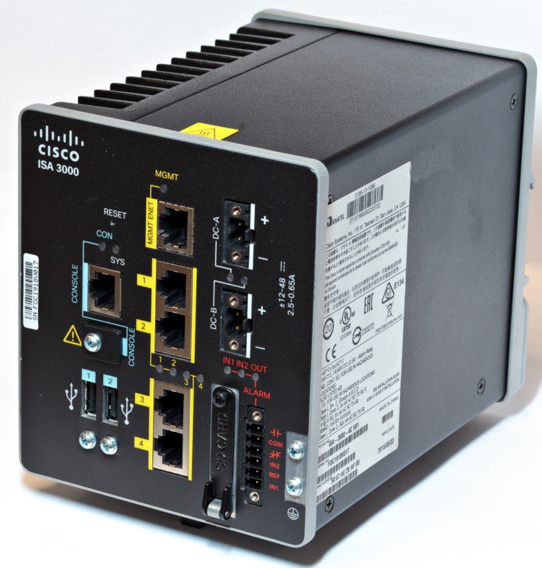
The Cisco ISA 3000 is a DIN Rail mounted ruggedized industrial security appliance that provides firewall, threat defense, and VPN services. The term DIN Rail describes a metal rail of a standard type widely used for mounting circuit breakers and industrial control equipment inside equipment racks. The term derives from the original specifications published by Deutsches Institut für Normung (DIN) in Germany. The device can run either the ASA or Firepower Threat Defense operating system.

The Cisco ISA 3000 is low-power, fan-less, with Gigabit Ethernet and a dedicated management port. There are two SKUs:

  • ISA3000-4C-K9 — Copper SKU with 4x10/100/1000Base-T with a management port.

  • ISA3000-2C2F-K9 — Fiber SKU with 2x1GbE SFP and 2x10/100/1000Base-T with a management port.

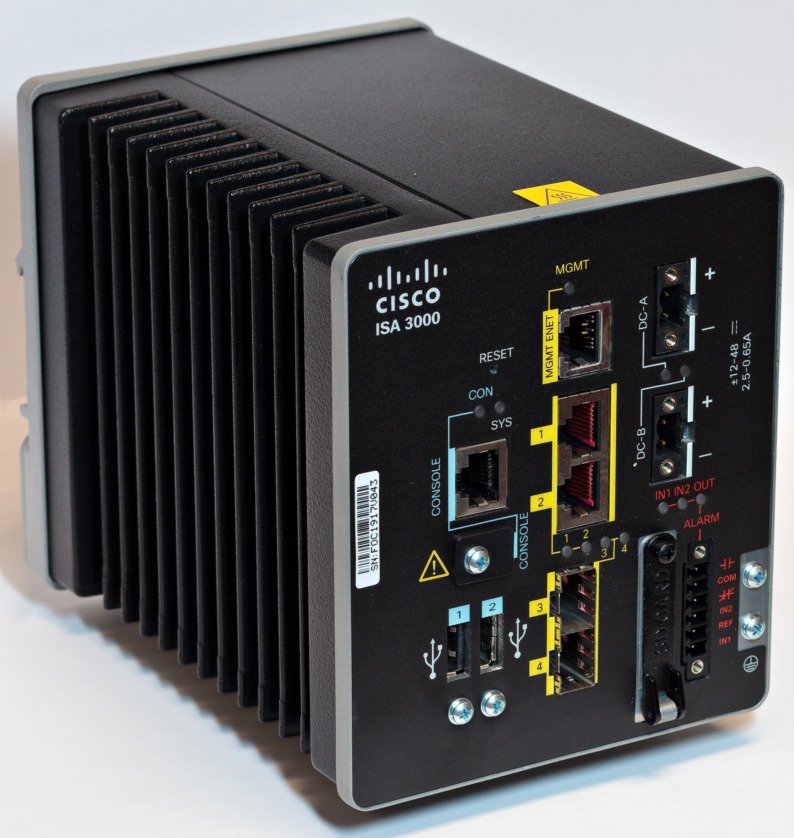
The following figures show the front panel details of the two SKUs

Figure 1. Cisco ISA 3000 Copper SKU

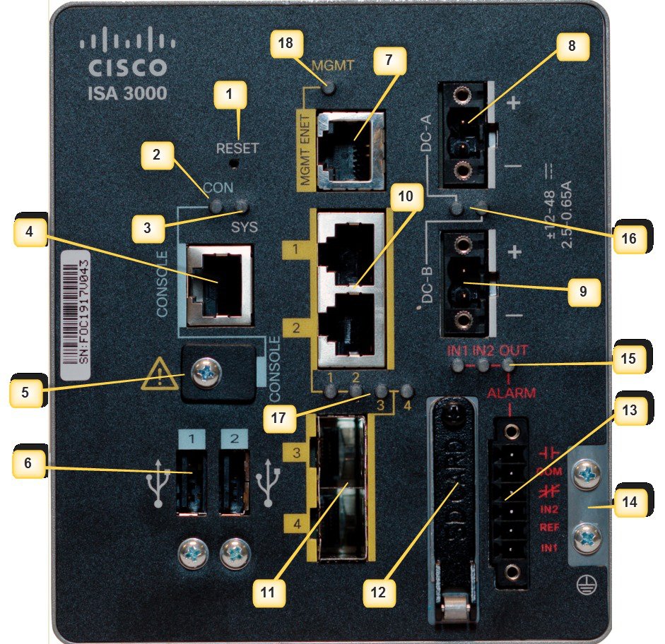
The following figure describes the front panel features:

Figure 2. Cisco ISA 3000 Fiber SKU
Figure 3. Cisco ISA 3000 Front Panel

PIN

Description

PIN

Description

1

Reset Pinhole Access

10

RJ45 10/100/100 BaseT Connectors 1&2

2

Console LED

11

On the ISA-3000-2C2F SKU, these are the SFP sockets.

On the ISA-3000-4C SKU, these are RJ45 10/100/100 BaseT Connectors 3&4

3

System LED

12

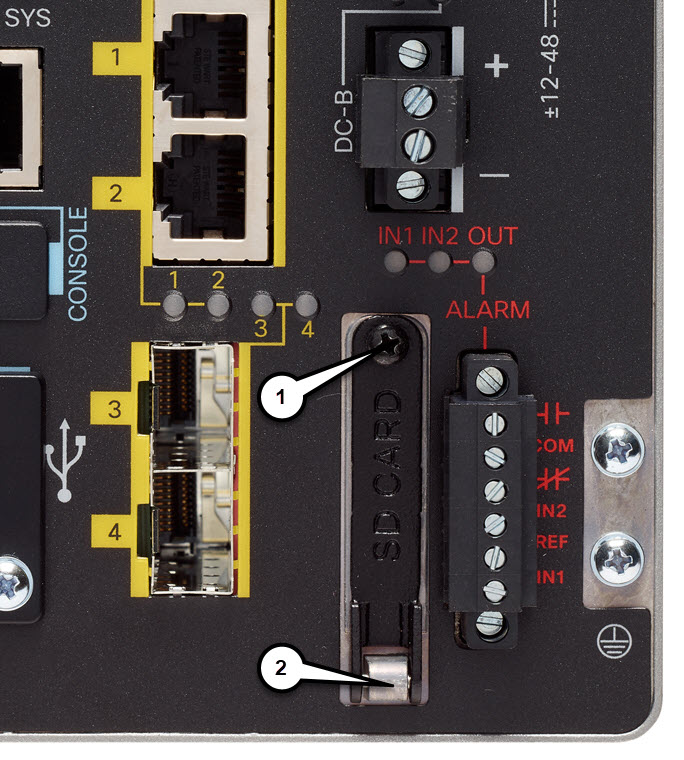
1GB removable SD flash memory card slot

4

Console connector (RJ-45)

13

Alarm Connectors

5

Console connector (mini-USB)

14

Grounding Point

6

USB connectors

15

Alarm LEDs

7

Management Interface

16

DC Power LEDs

8

DC power connection A

17

Gigabit Ethernet LEDs

9

DC power connection B

18

Management LED

ISA 3000 Shutdown

There is a new graceful shutdown option supported for Firepower Threat Defense as of 7.0.2/7.2. There is also an LED change new for 7.0.5/7.3. Use shutdown when you intend to remove the device from the network, for example to replace it, or for any scheduled maintenance.

There is no change to procedures with ASA.


Note


It is recommended to wait for10 seconds after the System LED is switched OFF to unplug the power from the device.

After shutting down the device, you can turn it back on only by Power cycling the device. There is no hardware On/Off switch for the device on the chassis. Power up the device to restart the device again.

LEDs

The following table describes the LEDs for the Cisco ISA 3000.

Table 1. LED Descriptions

LED

Activity

Description

System

Power Status

Off — No power

Green Steady on — Normal operation

Green Flashing — Boot up phase

Red Flashing — BIOS and POST

Red — System is not functioning properly.

MGMT

Management Port Status

Off — No link (default)

Green Steady on — Port link with no activity

Green Flashing — Transmitting and Receiving data

DC_A

DC_B

DC Power Status

Off — Power is not present

Green Steady on — Power is present on the associated circuit. (Hardware controlled)

Red Steady on — Power is not present on the associated circuit, and the system is configured for dual-input power

Alarm Out

Alarm monitoring

Off — Alarm Out not configured or the system is off (Default)

Green Steady on — Alarm Out is configured, no alarm detected.

Red Steady on — Minor alarm detected

Red Flashing — Major alarm detected

Alarm In 1&2

Alarm monitoring

Off — Alarm In not configured or the system is off (Default)

Green Steady on — Alarm In is configured, no alarm detected.

Red Steady on — Minor alarm detected

Red Flashing — Major alarm detected

Ethernet Ports

Link Status

Off — No link

Green Steady on — Link is up

Green Flashing — Transmitting and Receiving data

Amber — Fault, check log

Port 1&2 and in the copper SKU, 3&4 LEDs fast blink amber together — Those two ports are in bypass mode.

Console

Console connection Status

Off — RJ-45 is being used for console

Green — Mini USB is being used for console

Memory and Storage

The Cisco ISA 3000 has the following:

  • 8-GB DRAM (soldered down).

  • 16-GB onboard flash memory

  • 64-GB mSATA solid state drive (SSD)

  • 1-GB removable SD flash memory card - industrial temp

USB Ports

The Cisco ISA 3000 has two externally accessible Type-A USB (4-pin) connectors. Each USB port will support output powering of 5 volts and up to a maximum of 500 mA.

Management Ethernet Port

A management-only 10/100/1000 BaseT Ethernet port is provided. This port will be the only port able to be used for booting over the network, or for initial setup and management of the system. This port is Management 1/1 in the configuration.

Console Port

The Cisco ISA 3000 can be configured through a web interface, or through the console port. The console port is either a RJ45 or a Mini USB connector. A standard management cable (Part number 72-3383-01) can be used to convert the RJ45 to DB9 connector.

The default configuration settings for the RJ45 console port are:

  • 9600 baud, 8 data bits, no parity, 1 stop bit, no flow control.

  • If the USB Console Port is active (cable inserted and remote PC drivers are enabled) by default the console will switch from RJ45 to USB when the USB cable is detected. If both ports are connected, the Mini USB console port is used.

If your laptop or PC warns you that you do not have the proper drivers to communicate with the device, you can obtain them from your computers manufacturer, or go here:

https://software.cisco.com/download/home/282774227/type/282855122/release/3.1

The following table shows the pin-outs for the CON/AUX RJ-45 connector:

Table 2. RJ-45 Pinouts

Pin

Signal

Direction

1

DTR

Output

2

3.3

Output

3

TXD

Output

4

GND

-

5

GND

-

6

RXD

Input

7

-

NC

8

-

NC


Note


The console port will not support a remote dial-in modem.

Hardware Features

This section provides an overview of the following hardware features for the Cisco ISA 3000.

Platform Features for the Cisco ISA 3000

The following lists the hardware platform features.

  • CPU Intel 4 Core 1.25Ghz

  • 8 GB of 1333MHz DDR3 Memory

  • Dedicated management-only Gigabit Ethernet port

  • Mini-USB and RJ45 Console port

  • +/- 12 to 48VDC Rated (9.6 to 60VDC Maximum) redundant power connectors with 24-12 AWG screw cage terminals

  • Two external USB-A ports for addition of memory cards, security tokens, modems, or other USB 2.0 compliant devices

  • DIN Rail mount incorporated into the chassis

  • Fan-less design

  • Fault relay outputs and 2 alarm inputs

  • Industrial temperature SDHC card support

  • Redundant power inputs

  • Secure boot support

  • Bypass Relay (only available on copper ports)

Reset Button

The Reset button resets the security appliance configuration to the default configuration set by the factory. To restore the security appliance configuration to the default configuration set by the factory, use a standard size #1 paper clip with wire gauge 0.033 inch or smaller and simultaneously press the reset button while applying power to the security appliance.

When depressed the push-button follows these actions:

  • Depressed 0 to < 3 seconds or > 15 seconds — No action is taken.

  • Depressed > 3 seconds < 15 seconds — ASA: After reboot, the unit will be running the original factory default configuration, including ROMMON variables.

  • Depressed > 3 seconds < 15 seconds — FTD (7.0+) using Firepower Management Center: If you have a backup configuration on an SD card, a zero-touch restore is initiated.

Power Supply

The Cisco ISA 3000 comes with redundant external power connector. the connector supports 12 - 48 VDC. The connectors are Molex 5.00mm Pitch Eurostyle™ Horizontal Plug, with Retention Screws.

The power supply does not support reverse polarity, but does have reverse polarity protection. This means if you reverse + & - connections, the system will not power on but there will be no damage.

The + terminal always has to be greater than the - terminal for the system to operate. The difference is in the system grounding scheme used.

The ISA 3000 supports 3 basic schemes:

  • Isolated DC in, neither + nor - terminal is tied to chassis GND

  • Positive DC in, negative (-) terminal is tied to chassis GND

  • Negative DC in, positive (+) terminal is tied to chassis GND


Note


To ensure uninterrupted operation the redundant power connections must be connected to independently separated power sources.

1GB Removable SD Flash Memory Card

The Cisco ISA 3000 has a removable SD flash memory slot (referred to as SD). This is primarily to allow easy updates, copying of logs and crash-dumps. The device does not come with a removable SD flash memory card installed, this is an optional spare item, Cisco part number SD-IE-1GB=. Contact your Cisco Marketing Representative for ordering information.


Note


Check the software guide for the operating system you are running for information on SD memory support.

Installing or Removing the SD Card (Optional)


Warning


Do not insert or remove the SD card while power is on; an electrical arc can occur. This could cause an explosion in hazardous location installations. Be sure that power is removed or the area is nonhazardous before proceeding. Statement 379

The SD card is hidden under a protective cover:

Figure 4. SD Card Cover

1

Phillips screw

2

Door pivot point

For hazardous locations environments, if you are installing or removing the flash card or alarm wiring, follow these warnings:


Warning


When you connect or disconnect the power and/or alarm connector with power applied, an electrical arc can occur. This could cause an explosion in hazardous area installations. Be sure that all power is removed from the device and any other circuits. Be sure that power cannot be accidentally turned on or verify that the area is nonhazardous before proceeding. Statement 1058

Warning


Do not insert or remove the flash card while power is on; an electrical arc can occur. This could cause an explosion in hazardous location installations. Be sure that power is removed or the area is nonhazardous before proceeding. Statement 379

Caution


Use a ratcheting torque flathead screwdriver to torque the power connector captive screws to 5 in-lb (0.6 N-m), the maximum recommended torque.

To install or replace the SD card, follow these steps:

  1. On the front of the device, locate the door that protects the SD card slot. Loosen the captive screw at the top of the door using a Phillips screwdriver to open the door.

    • To install a card, slide it into the slot, and press it in until it clicks in place. The card is keyed so that you cannot insert it the wrong way.

    • To remove the card, push it in until it releases for it to pop out. Place it in an antistatic bag to protect it from static discharge.

  2. After the card is installed, close the guard door and fasten the captive screw using a Phillips screwdriver to keep the door in place.

Alarm Ports

The Cisco ISA 3000 has alarm ports. There are two conditions that generate an alarm:

  • When dual power supply is configured, and there is a failed or missing power supply.

  • When the CPU temperature is in critical condition (below -40°C or above 105°C)

When either condition is met, the alarm LED turns red, and a syslog message and SNMP trap is triggered.


Note


Check the software guide for the operating system you are running for information on alarm port support.

Power Supply

The device can be configured to run dual power supplies. When set, the system expects to see both power supplies functioning properly.


Note


Check the software guide for the operating system you are running for information on dual power supply configuration and support.

When configured for dual power supply, and a failure occurs, the Alarm Out LED turns red. The alarm relay is also energized. A syslog message is generated:

Syslog: %ASA-1-735006: Power Supply Unit Redundancy Lost

When configured for dual power supply, and a failure recovers, the Alarm Out LED turns off. A syslog message is generated:

Syslog: %ASA-1-735005: Power Supply Unit Redundancy OK

Temperature Sensor

The operating system monitors the CPU temperature when it is running.

If the CPU temperature is in a critical condition (below -40°C or above 105°C), the Alarm Out LED turns red.

When the CPU temperature returns to a normal condition, the Alarm Out LED turns off.


Note


The critical range of temperature is not configurable. It is hard coded as below -40°C or above 105°C.