Cisco XR 12000 Series Packet-Over-SONET Line Card Installation
Available Languages
Table Of Contents
Packet-Over-SONET Line Card Installation
OC-3c/STM-1c ISE POS Line Card
4-Port OC-12c/STM-4c ISE POS Line Card
OC-48c/STM-16c ISE POS Line Card
Preventing Electrostatic Discharge
Removing and Installing a Line Card
Guidelines for Line Card Removal and Installation
Line Card Cable-Management Bracket
Removing a Line Card Cable-Management Bracket
Installing a Line Card Cable-Management Bracket
Power Budget and Signal Specifications
OC-3c/STM-1c ISE POS Line Card Power Specifications
4-Port OC-12c/STM-4c ISE POS Line Card Power Specifications
OC-48c/STM-16c ISE POS Line Card Power Specifications
Removing and Installing Interface Cables
Verifying and Troubleshooting the Line Card Installation
Troubleshooting the Installation
ISE Line Card Memory Locations
POS Line Card Route Memory Options
POS Line Card Packet Memory Options
Removing and Installing Line Card Memory
Checking the Installation of Line Card Memory
Regulatory, Compliance, and Safety Information
Translated Safety Warnings and Agency Approvals
Electromagnetic Compatibility Regulatory Statements
Class A Notice for Taiwan and Other Traditional Chinese Markets
VCCI Compliance for Class B Equipment
Class 1M Laser Product Warnings (VSR Only)
Obtaining Documentation and Submitting a Service Request
Packet-Over-SONET Line Card Installation
Published: March 7, 2006Revised: November 30, 2009, Release 3.2, Part Number 78-16412-01, Rev. B0
This hardware installation note contains instructions for installing and troubleshooting Packet-over-SONET (POS) line cards on supported Cisco XR 12000 Series Routers.
Contents
This installation and configuration guide includes the following sections:
•
Removing and Installing a Line Card
•
•
•
•
•
Important Information
This section contains important information about the following:
•
POS Line Card Product Numbers
Table 1 lists the Cisco product numbers to which this publication applies. This guide replaces the individual POS line card installation and configuration documents for the Cisco XR 12000 Series Router.
Router Hardware Installation
For hardware installation and configuration information for Cisco XR 12000 Series Routers, refer to the installation and configuration guide for your router. The guide includes information on the router switch fabric and how it affects operation of the line card, as well as line card slot locations, slot width, and other requirements.
Also refer to the field-replaceable unit (FRU) publications that describe how to install, maintain, and replace router subsystems, such as cooling fans, power supplies, chassis backplanes, and so on.
Supported Platforms
Table 2 lists the supported router platforms for POS line cards.

Note
See Table 13 for information on the engine of each line card. See the appropriate Cisco XR 12000 Series Router installation and configuration guide for information about the switch fabric and other related requirements.
Memory Options
POS line card memory options vary by line card. See "Line Card Memory" section for more information.
Related Documentation
This publication describes the basic installation and initial configuration of a POS line card. For complete configuration information, refer to the following publications:
•
•
•
•
See the "Obtaining Documentation and Submitting a Service Request" section for information on how to obtain these publications.
Product Overviews
The following sections provide information about the POS line card products:
•
•
•
POS Line Card Comparison
Table 3 provides comparative information about POS line cards.
OC-3c/STM-1c ISE POS Line Card
Note
These line cards provide Cisco XR 12000 Series Routers with 155 Mbps of bandwidth for each interface and are concatenated, which provides for increased efficiency by eliminating the need to partition the bandwidth. Table 4 lists the different versions of the OC-3c/STM-1c ISE POS line card that are available.
Table 4 OC-3c/STM-1c ISE POS Line Card Versions
4-Port OC-3c/STM-1c ISE
4OC3X/POS-IR-LC-B=
4
IR
Single-mode
LC
4OC3X/POS-MM-MJ-B=
4
SR
Multimode
MTRJ
4OC3X/POS-LR-LC-B=
4
LR
Single-mode
LC
8-Port OC-3c/STM-1c ISE
8OC3X/POS-IR-LC-B=
8
IR
Single-mode
LC
8OC3X/POS-MM-MJ-B=
8
SR
Multimode
MTRJ
16-Port OC-3c/STM-1c ISE
16OC3X/POS-I-LC-B=
16
IR
Single-mode
LC
16OC3X/POS-M-MJ-B=
16
SR
Multi-mode
MTRJ
1 Intermediate-reach (IR), short-reach (SR), long-reach (LR)
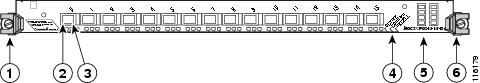
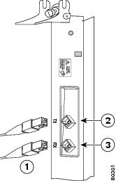
Figure 1 and Figure 2 show the 4-port versions of the line card.
Figure 1 4-Port OC-3c/STM-1c ISE POS Line Card, LC Version
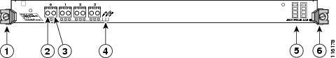
Figure 2 4-Port OC-3c/STM-1c ISE POS Line Card, MTRJ Version
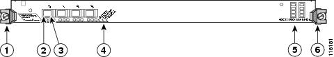
Figure 3 and Figure 4 show the 8-port versions of the line card.
Figure 3 8-Port OC-3c/STM-1c ISE POS Line Card, LC Version
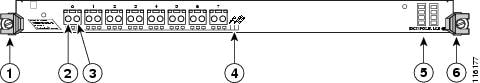
Figure 4 8-Port OC-3c/STM-1c ISE POS Line Card, MTRJ Version
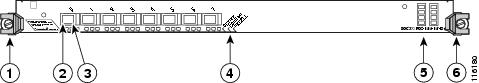
Figure 5 and Figure 6 show the 16-port versions of the line card.
Figure 5 16-Port OC-3c/STM-1c ISE POS Line Card, LC Version
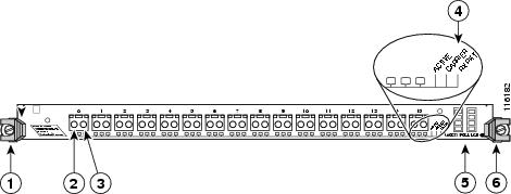
Figure 6 16-Port OC-3c/STM-1c ISE POS Line Card, MTRJ Version
The OC-3c/STM-1c ISE POS line card ships with 512 MB of packet memory, which is not field serviceable. Additionally, the line card route processor memory has a default configuration of 256 MB and can be upgraded to 512 MB. See the "Line Card Memory" section for more information.
4-Port OC-12c/STM-4c ISE POS Line Card
The 4-port OC-12c/STM-4c ISE POS line card provides the Cisco XR 12000 Series Routers with four 622-Mbps concatenated POS interfaces on a single card and provides four OC-12c/STM-4c full-duplex single-mode intermediate-reach interfaces or multimode short-reach interfaces.
Figure 7 shows a front view of the 4-port OC-12c/STM-4c ISE POS line card.
Figure 7 4-Port OC-12c/STM-4c ISE POS Line Card Front Panel

For SONET fiber-optic connections, use one duplex SC-type connector or two simplex SC-type connectors.
The 4-port OC-12c/STM-4c ISE POS line card route memory default is 256 MB and is upgradeable to 512 MB. It has 512 MB of packet memory. See the "Line Card Memory" section for more information.
OC-48c/STM-16c ISE POS Line Card
The OC-48c/STM-16c ISE POS line card provides the Cisco XR 12000 Series Router with a single 2.5-Gbps POS interface on a single card and an OC-48/STM-16 full duplex single-mode interface. There is a short- reach and a long-reach version of the line card.
Figure 8 shows a front view of the OC-48c/STM-16c ISE POS line card.
Figure 8 OC-48c/STM-16c ISE POS Line Card Front Panel and Backplane Connector
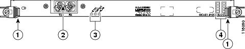
The line card route memory default is 256 MB and is upgradeable to 512 MB. It has 512 MB of packet memory. See the "Line Card Memory" section for more information.
Preparing for Installation
The following sections provide information about preparing to install line cards:
•
Safety Guidelines
Before you perform any procedure in this publication, review the safety guidelines in this section to avoid injuring yourself or damaging the equipment.
The following guidelines are for your safety and to protect equipment. The guidelines do not include all hazards. Be alert.
Note
•
•
•
Before working with laser optics, see the "Laser Safety" section.
Preventing Electrostatic Discharge
Electrostatic discharge (ESD) damage, which can occur when electronic cards or components are improperly handled, results in complete or intermittent failures. Electromagnetic interference (EMI) shielding is an integral component of the line card. We recommend using an ESD-preventive strap whenever you are handling network equipment or one of its components.
The following are guidelines for preventing ESD damage:
•
•
•
•

Warning
Required Tools and Equipment
You need the following tools and parts to remove and install POS line cards:
•
•
•
•
Note
Refer to the individual line card descriptions in the "Product Overviews" section for more information. Table 3 summarizes the hardware requirements for each POS line card.
See the "Line Card Interface Cables" section for information on required interface cables.
Removing and Installing a Line Card
The following sections provide procedures for removing or installing a line card:
•
Note
Note
Guidelines for Line Card Removal and Installation
Guidelines for line card removal and installation include the following:
•
Note
•

Caution
After removing and inserting a line card into the same slot, allow at least 60 seconds before removing or inserting another line card.
•
Caution
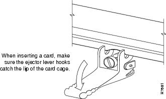
When you install a line card, always use the ejector levers to ensure that the card is correctly aligned with the backplane connector; the connector pins should make contact with the backplane in the correct order, indicating that the card is fully seated in the backplane. If a card is only partially seated in the backplane, the router hangs and subsequently crashes.
For line card configuration information, see the IOS XR Software Configuration Guide.
Removing a Line Card
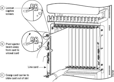
If you are replacing a failed line card, remove the existing line card first, then install the new line card in the same slot. To remove a line card, use Figure 9 as a reference and follow these steps:
Step 1
Step 2
Step 3
Step 4
Figure 9 Line Card Removal and Installation
Caution
Step 5
Step 6
Step 7
Step 8
Step 9
Note
Warning
Caution
Note
For information on disconnecting interface cables, see the "Removing and Installing Interface Cables" section.
For information on removing the cable-management bracket, see the "Line Card Cable-Management Bracket" section.
Installing a Line Card
A line card slides into almost any available line card slot and connects directly to the backplane. If you install a new line card, you must first remove the line card blank from the available slot.
Note
Caution
To install a line card, follow these steps:
Step 1
Step 2
Caution
Step 3
Step 4
Figure 10 Ejector Levers
Caution
Step 5
Step 6
Caution
Step 7
Step 8
Step 9
For information on installing cable-management brackets, see the "Installing a Line Card Cable-Management Bracket" section.
For information on installing SFP modules, see the "Line Card Cable-Management Bracket" section.
For information on installing interface cables, see the "Removing and Installing Interface Cables" section.
For information on verifying and troubleshooting the hardware installation, see the "Verifying and Troubleshooting the Line Card Installation" section.
Line Card Cable-Management Bracket
Note
Cisco XR 12000 Series Routers include a cable-management system that organizes the interface cables entering and exiting the router, keeping them out of the way and free of sharp bends.
Caution
The cable-management system consists of two separate components:
1.
2.
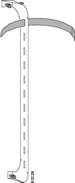
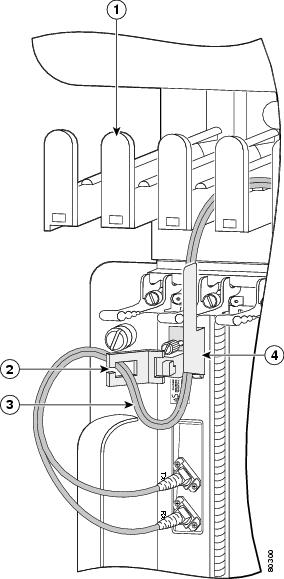
This section describes the line card cable-management bracket. Figure 11 shows the single-port line card cable-management bracket; Figure 12 shows the multiport line card cable-management bracket.
Figure 11 Single-Port Line Card Cable-Management Bracket
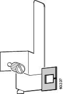
Figure 12 Multiport Line Card Cable-Management Bracket
Note
Caution
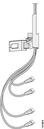
When more than two fibers are used, they should not loop through the rubber hook, but should pass through the bracket as shown in Figure 13.
Figure 13 Single-Port Line Card Cable-Management Bracket with Multiple Fibers
Removing and installing the line card cable-management bracket is described in the following procedures:
•
•
Removing a Line Card Cable-Management Bracket
To remove a line card cable-management bracket, follow these steps:
Step 1
Step 2
Step 3
Note
Step 4
For single-port line card cable-management brackets, carefully remove the interface cable from the cable clip. (See Figure 15.) Avoid any kinks or sharp bends in the cable.
Step 5
Step 6
For single-port line card cable-management brackets, loosen the captive installation screw on the cable-management bracket and remove the bracket from the line card.
Figure 14 Multiport Line Card Cable-Management Installation and Removal
(4-Port OC-48c/STM-16c DPT Line Card Shown)
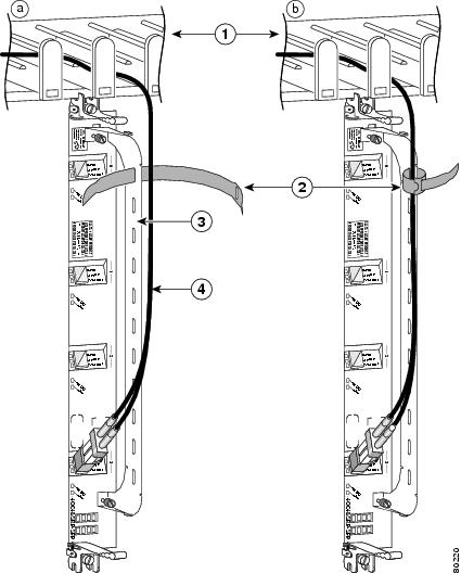
Figure 15 Single-Port Line Card Cable-Management Bracket Installation and Removal (1-Port OC-192c/STM-64c DPT Line Card Shown)
Installing a Line Card Cable-Management Bracket
To install a line card cable-management bracket, follow these steps:
Step 1
Step 2
a.
b.
c.
Step 3
For single-port line card cable-management brackets, carefully press the interface cable onto the cable clip. (See Figure 15.) Avoid any kinks or sharp bends in the cable.
For information on disconnecting and connecting interface cables, see the "Removing and Installing Interface Cables" section.
Cabling and Specifications
The following sections provide informaton about specifications and cabling for POS line cards:
•
Packet-Over-SONET Interface
POS is a high-speed method of transporting Internet Protocol (IP) traffic between two points. This technology combines the Point-to-Point Protocol (PPP) with Synchronous Optical Network (SONET) and Synchronous Digital Hierarchy (SDH) interfaces.
PPP was designed as a standard method of communicating over point-to-point links. Initial deployment was over short local lines, leased lines, and plain-old-telephone-service (POTS) (also called basic telephone service) for users of modems. As new packet services and higher speed lines are introduced, PPP can be deployed easily in these environments as well.
SONET is an octet-synchronous multiplex scheme defined by the American National Standards Institute (ANSI) standard (T1.1051988) for optical digital transmission at hierarchical rates from 51.840 Mbps to 2.5 Gbps (Synchronous Transport Signal, STS-1 to STS-48) and greater. SDH is an equivalent international standard for optical digital transmission at hierarchical rates from 155.520 Mbps (STM-1) to 2.5 gigabits per second (Gbps) (STM-16) and greater. SONET electrical specifications have been defined for single-mode fiber, multimode fiber, and CATV 75-ohm coaxial cable. (For example, the 4-port OC-3c/STM-1c POS line card allows transmission over single-mode and multimode optical fiber at Optical Carrier 3 [OC-3] rates. OC-3 is the Optical Carrier 3 specification for SONET STS-3c and SDH STM-1 transmission rates.)
SONET/SDH transmission rates are integral multiples of 51.840 Mbps. The following transmission multiples are currently specified and commonly used:
•
•
•
•
The POS specification (RFC 1619) describes the use of PPP encapsulation over SONET/SDH links. Because SONET/SDH is, by definition, a point-to-point circuit, PPP is well-suited for use over these links. PPP treats SONET/SDH transport as octet-oriented full-duplex synchronous links. PPP presents an octet interface to the physical layer. The octet stream is mapped into the SONET/SDH Synchronous Payload Envelope (SPE), with the octet boundaries aligned with the SPE octet boundaries. The PPP frames are located by row within the SPE payload. Because frames are variable in length, the frames are allowed to cross SPE boundaries.
The basic rate for POS is OC-3/STM-1, which is 155.520 Mbps. The available information bandwidth is 149.760 Mbps, which is the OC-3c/STM-1 SPE with section, line, and path overhead removed.
Power Budget and Signal Specifications
The SONET specification for fiber-optic transmission defines two types of fiber: single-mode and multimode. Signals can travel farther through single-mode fiber than through multimode fiber.
The maximum distance for installations is determined by the amount of light loss in the fiber path. If your environment requires the signal to travel close to the typical maximum distance, you should use an optical time domain reflectometer (OTDR) to measure the power loss.
This section contains the following:
•
•
•
OC-3c/STM-1c ISE POS Line Card Power Specifications
All OC-3c/STM-1c ISE POS line cards provide155 Mbps laser-based SONET/SDH-compliant interfaces. Table 5 lists the power ratings and distances of each line card. The actual distance in any given case depends on the quality of the fiber attached to the transceiver.
All versions of the line card meet both the EN60825\IEC60825 and FDA - Code of Federal Regulations (USA) laser safety standards.
Table 5 OC-3c/STM-1c ISE POS Line Card Power Specifications
Multimode, short-reach
9 dBm
-20 dBm to -14 dBm
-30 dBm to -14 dBm
1.2 miles (2 km)
Single-mode, intermediate-reach
12 dBm
-20 dBm to -14 dBm
-28 to -8 dBm
9.3 miles (15 km)
Single-mode, long-reach
28 dBm
-20 dBm to -14 dBm
-34 dBm to -10 dBm
24.8 miles (40 km)
1 IR optic is standard compliant with G.957 S-1.1 and GR-235 IR-1. LR optic is standard compliant with G.957 L-1.1 and GR-235 LR-1.
2 All power budgets include a 1 dB optical path penalty.
3 Measurement Conditions:Transmit power is measured at the end of 1 meter of 62.5/125um, numerical aperture =0.275 unattenuated optical fiber with cladding modes removed. When using 50/125um unattenuated optical fiber with cladding modes removed, the numerical aperture = 0.20 Fiber for the test, and the minimum optical power is -23.5dBm.
4-Port OC-12c/STM-4c ISE POS Line Card Power Specifications
Table 6 lists the specifications for these line cards.
OC-48c/STM-16c ISE POS Line Card Power Specifications
Good quality single-mode fiber with very few splices can carry the short-reach and long-reach compliant OC-48/STM-16 signals. If your environment requires the light to travel close to the typical maximum distance (as listed in Table 7), use an OTDR to measure the power loss.
Line Card Interface Cables
The following types of cables are used with POS line cards to connect your router to another router or switch:
•
•
Note
The following types of cable connectors are used with POS line cards:
•
•
•
•
•
Figure 16 Simplex SC Cable Connector (Single-mode)
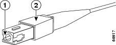
Figure 17 Duplex SC Cable Connector
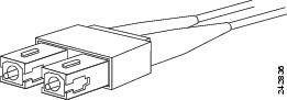
Figure 18 Simplex MTP Cable Connector (Multimode - VSR Only)
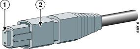
Figure 19 Simplex LC Cable Connector
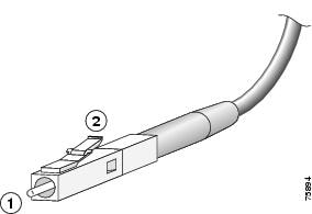
Figure 20 Simplex FC Cable Connector
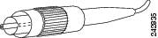
Figure 21 MTRJ Cable Connector (Orange)
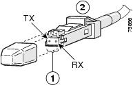
Attach one simplex or duplex fiber cable between the line card and the device to which the line card is connected. Observe the receive (RX) and transmit (TX) cable relationship shown in Figure 22.
Table 8 lists the required specifications for very-short-reach (VSR) cables.
Note
Removing and Installing Interface Cables
To remove an interface cable, follow these steps:
Step 1
Step 2
Step 3
Warning
Warning
Warning
Step 4
To install an interface cable, follow these steps:
Step 1
Step 2
Step 3
Figure 22 Attaching Fiber Cables (Simplex, SC Connectors Shown)
Step 4
Note
Verifying and Troubleshooting the Line Card Installation
The following sections describe how to verify and troubleshoot line card installation:
•
Initial Boot Process
Note
During a typical line card boot process, the following events occur:
1.
2.
3.
To verify that the line card is working properly, perform the following operational checks:
•
•
If one of these conditions is not met, refer to the IOS XR Software Configuration Guide to identify any possible problems.
Alphanumeric LEDs
POS line cards have two four-digit alphanumeric LED displays at one end of the faceplate, near the ejector lever, that display a sequence of messages indicating the state of the card. In general, the LEDs do not turn on until the RP recognizes and powers up the card. As it boots, the line card displays a sequence of messages similar to those in Table 9.
Note
Table 9 Alphanumeric LED Messages During a Typical Initialization Sequence
MROM
nnnnMBus microcode execute; nnnn is the microcode version number.
MBus controller
LMEM
TESTLow memory on the line card is being tested.
Line card ROM monitor
LROM
RUNLow memory test has been completed.
Line card ROM monitor
BSS
INITMain memory is being initialized.
Line card ROM monitor
RST
SAVEContents of the reset reason register are being saved.
Line card ROM monitor
IO
RSTReset I/O register is being accessed.
Line card ROM monitor
EXPT
INITInterrupt handlers are being initialized.
Line card ROM monitor
TLB
INITTLB is being initialized.
Line card ROM monitor
CACH
INITCPU data and instruction cache is being initialized.
Line card ROM monitor
MEM
INITSize of the main memory on the line card is being discovered.
Line card ROM monitor
LROM
RDYROM is ready for the download attempt.
Line card ROM monitor
ROMI
GETROM image is being loaded into line card memory.
RP IOS software
ROM
VGET2ROM image is receiving a response.
RP IOS software
FABI
WAITLine card is waiting for the fabric downloader to load.3
RP IOS software
FABM
WAIT2Line card is waiting for the fabric manager to report that the fabric is usable.
RP IOS software
FABL
DNLDFabric downloader is being loaded into line card memory.
RP IOS software
FABL
STRTFabric downloader is being launched.
RP IOS software
FABL
RUNFabric downloader has been launched and is running.
RP IOS software
IOS
DNLDCisco IOS software is being downloaded into line card memory.
RP IOS software
IOS
FABW2Cisco IOS software is waiting for the fabric to be ready.
RP IOS software
IOS
VGET2Line card is obtaining the Cisco IOS version.
RP IOS software
IOS
RUNLine card is enabled and ready for use.
RP IOS software
IOS
STRTCisco IOS software is being launched.
RP IOS software
IOS
TRANCisco IOS software is transitioning to active.
RP IOS software
IOS
UPCisco IOS software is running.
RP IOS software
1 The entire LED sequence shown in Table 9 might occur too quickly for you to read; therefore, this sequence is provided in this tabular form as a baseline for how a line card should function at startup.
2 This LED sequence only appears in Cisco IOS release 12.0(24)S or later.
3 The fabric downloader loads the Cisco IOS software image onto the line card.
Table 10 lists other messages displayed on the line card alphanumeric LED displays.
Table 10 Other Alphanumeric LED Messages
MAL
FUNCLine card malfunction reported by field diagnostics.
RP
MISM
ATCH1Line card type mismatch in paired slots.
RP
PWR
STRT1Line card has been newly powered on.
RP
PWR
ONLine card is powered on.
RP
IN
RSETIn reset.
RP
RSET
DONEReset complete.
RP
MBUS
DNLDMBus agent downloading.
RP
MBUS
DONEMBus agent download complete.
RP
ROMI
DONEAcquisition of ROM image complete.
RP
MSTR
WAITWaiting for mastership determination.
RP
CLOK
WAITWaiting for slot clock configuration.
RP
CLOK
DONESlot clock configuration done.
RP
FABL
LOADLoading fabric downloader2 complete.
RP
IOS
LOADDownloading of Cisco IOS software is complete.
RP
BMA
ERRCisco IOS software BMA error.
RP
FIA
ERRCisco IOS fabric interface ASIC configuration error.
RP
CARV
ERRBuffer carving failure.
RP
DUMP
REQLine card requesting a core dump.
RP
DUMP
RUNLine card dumping core.
RP
DUMP
DONELine card core dump complete.
RP
DIAG
MODEDiagnostic mode.
RP
DIAG
LOADDownloading field diagnostics over the MBus.
RP
DIAG
F_LDDownloading field diagnostics over the fabric.
RP
DIAG
STRTLaunching field diagnostics.
RP
DIAG
HALTCancel field diagnostics.
RP
DIAG
TESTRunning field diagnostics tests.
RP
DIAG
PASS1Field diagnostics were completed successfully.
RP
POST
STRTLaunching power-on self-test (POST).
RP
UNKN
STATUnknown state.
RP
ADMN
DOWNLine card is administratively down.
RP
SCFG
PRES1Incorrect hw-module slot srp command entered.
RP
SCFG1
REDQRequired hw-module slot srp command not entered.
RP
1 This LED sequence only appears in Cisco IOS release 12.0(24)S or later.
2 The fabric downloader loads the Cisco IOS software image onto the line card.
Status LEDs
Interface status LEDs show the status of each fiber-optic connector. POS line cards contain the following status LEDs:
•
•
•
The status LEDs might not go on until after you have configured the line card interfaces (or turned them on, if they were shut down). To verify correct operation of each interface, complete the configuration procedures for the line card. (See the IOS XR Software Configuration Guide.)
The different operating states of the status LEDs are shown in Table 11 and Table 12.
Table 11 POS Line Card Status LED Descriptions
Green
Port is active.
Yellow (blinking)
Fiber misconnection detected (for example, side A is connected to neighbor side A).
Off
Port is not active.
Green
SONET frames are being received on this port.
Off
SONET frames are not being received on this port.
RX PKT
Green
Packets are being received on this port.2
Off
Packets are not being received on this port.
1 This LED remains on even if the interface is administratively down or if the link to the network is lost.
2 Packets forwarded back onto the ring do not trigger this LED.
Table 12 Explanation of Status LEDs
Off
Off
Off
Port is off.
On
Off
Off
Port is on.
On
On
Off
Line protocol is up.
On
On
Flash
Line card is receiving data.
Troubleshooting the Installation
Note
If the Active LED (Link LED or status LED for line cards with no Active LED) or the alphanumeric display LEDs on a line card do not go on, there is either a problem with the line card installation or a hardware failure. To verify that the line card is installed correctly, follow these steps:
Step 1
Step 2
a.
b.
c.
After the line card reinitializes, the Active LED on the line card should go on. If the Active LED goes on, the installation is complete; if the Active LED does not go on, proceed to the next step.
Step 3
•
•
Step 4
For more information on troubleshooting and diagnostics, refer to the installation and configuration guide that came with your Cisco XR 12000 Series Router.
Note
SONET/SDH Clocking Issues
This section provides an overview of SONET/SDH clocking issues. A POS line card supports both line and internal clocking functions. Line clocking is derived from the incoming signal from a given port. Internal clocking is derived from the clock that is internal to the line card.
Each port can be configured independently of any other in a line-timed setup, going back as far as the first payload processor. However, on a POS line card, the second level of payload processing ties the ports to a common clock source which is timed from only one port. This can result in pointer justifications if the remaining ports are not synchronous. However, with a properly configured router, these pointer justifications can be limited to provide the same performance as a SONET cross-connect device.
Note
The line card uses Stratum3 (S3) as the internal clock reference. However, if one of the ports is Stratum1 (S1) accurate, it can be used as the local reference for the system clock. In this case, pointer justifications are very limited. If the system clock is timed from an S1 clock source, from a valid SONET network, then there will be no pointer justifications on any synchronous interface. There are minimal pointer justifications (limited to S1 pointer justifications) on any asynchronous interface if it is on another SONET network. Pointer justification in this case is proportional to the accuracy of the other port clock.
A POS line card has the ability to select an input port as the source of synchronization for the system clock. This eliminates pointer justifications on any port that is synchronous with the selected port. Any other port on that line card that is not synchronous to the selected reference port will encounter pointer justifications at a rate proportional to clock accuracy of the port.
If the port is locally timed, it is Stratum3. If the port is line-timed, it depends on the attached network. It could be another Stratum3 clock, a Stratum1, or something much worse. This issue only applies to multiport cards and can be avoided if all ports on the line card are connected to the same SONET/SDH network.
Line Card Memory
This section contains information about the following:
•
You can replace the route memory on POS line cards. Route memory modules are installed into 144-pin small-outline DIMM (SODIMM) sockets. Route memory runs the Cisco IOS software image and stores the updated network routing tables downloaded from the route processor.
Table 13 provides information about the various hardware engines available with the POS line cards. The engine determines where the memory is placed.
Table 13 POS Line Card Engines
OC-3c/STM-1c ISE
Engine 3, Internet Services Engine (ISE)
4-Port OC-12c/STM-4c ISE
OC-48c/STM-16c ISE
Caution
Line Card Memory Locations
The following sections contain general line card memory information for each POS line card:
•
•
•
Memory removal and installation instructions are found in the "Removing and Installing Line Card Memory" section.
ISE Line Card Memory Locations
Figure 23 shows the small outline DIMM (SODIMM) socket locations on an ISE line card. This line card is equipped with 10 SODIMM sockets:
•
•
•
Figure 23 ISE Line Card Memory Locations
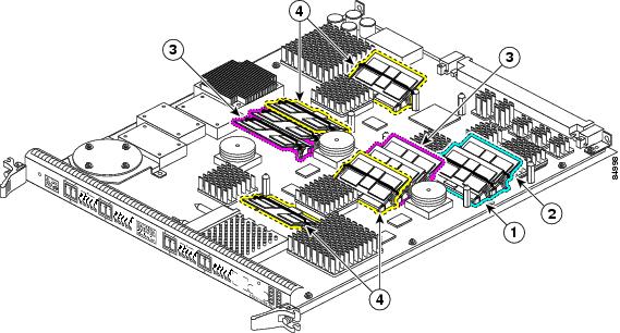
Route memory SODIMM0
Four packet memory SODIMM sockets (not field serviceable)
Route memory SODIMM1
Four TLU/PLU memory SODIMM sockets (not field serviceable)
POS Line Card Route Memory Options
Route memory runs the Cisco IOS software image and stores updated network routing tables downloaded from the route processor (RP). Line card route memory ranges from 128 MB to 512 MB. Table 14 lists the available route memory configurations and associated product numbers of the memory modules used for upgrading route memory on POS line cards. For the most up-to-date memory options, refer to Cisco 12000 Series Router Memory Replacement Instructions publication.
Table 14 Route Memory Configurations for POS Line Cards
512 MB
MEM-LC-ISE-512=1
2 256-MB DIMMs
DIMM0 and DIMM1
ISE
1 This option is the upgrade. The standard default DIMM configuration is 2 x 128 MB
POS Line Card Packet Memory Options
Line card packet memory temporarily stores data packets awaiting switching decisions by the line card processor. Once the line card processor makes the switching decisions, the packets are propagated into the router switch fabric for transmission to the appropriate line card.
Table 15 lists the packet memory options for POS line cards that have replaceable packet memory.
Caution
Table 15 POS Line Card Packet Memory Options
512 MB (upgrade)
MEM-PKT-512-UPG=2
2 RX 128-MB DIMMs
2 TX 128-MB DIMMsRX DIMM0 and DIMM1
TX DIMM0 and DIMM1
1 The DIMMs installed in a given buffer (either receive or transmit) must be the same type and size, but the individual receive and transmit buffers can operate with different memory capacities.
2 Only applicable to Engine 2 line cards.
Removing and Installing Line Card Memory
Before beginning the memory replacement procedures in this section, ensure that you have the proper tools and equipment at hand, and that you are using appropriate ESD-prevention equipment and techniques. When removing or installing memory, observe the guidelines in the following sections:
•
Removing a DIMM
To remove a DIMM from a line card, follow these steps:
Step 1
Step 2
Step 3
Note
Figure 24 DIMM Socket with Dual Release Levers
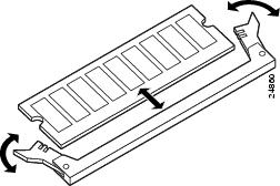
Figure 25 DIMM Socket with Single Release Lever
Step 4
•
or
•
Caution
Step 5
Step 6
Step 7
Installing a DIMM
This section contains instructions for installing DIMM memory into a line card.
Note
To install DIMMs in a line card, follow these steps:
Step 1
Step 2
Caution
Step 3
Step 4
Step 5
If necessary, rock the DIMM back and forth gently to align it in the socket.
Figure 26 Handling a DIMM
Caution
Step 6
Step 7
If the module appears misaligned, carefully remove it and reseat it, ensuring that the release lever is flush against the side of the DIMM socket.
Step 8
Removing a SODIMM
To remove a SODIMM, follow these steps:
Step 1
Step 2
Step 3
Step 4
Note
Caution
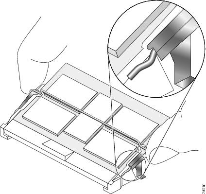
Figure 27 Remove Retaining Clip from Memory Module Socket
Step 5
Caution
Caution
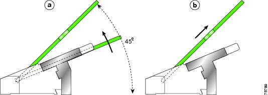
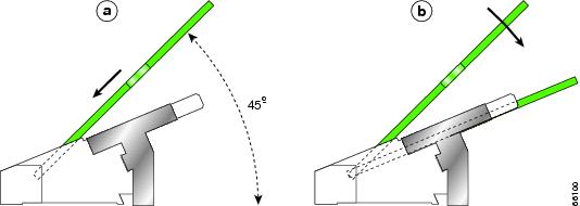
Figure 28 Moving the Plastic Latch Away from the SODIMM
Step 6
Figure 29 Removing a 144-pin SODIMM Module
Step 7
Installing a SODIMM
To install a SODIMM module, follow these steps:
Step 1
Step 2
Step 3
Note
Figure 30 SODIMM Socket Retaining Clip

Caution
Step 4
Step 5
Caution
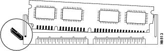
Step 6
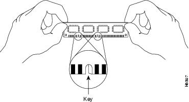
Figure 31 SODIMM with Key in Face-up Position
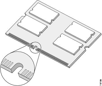
Step 7
Note
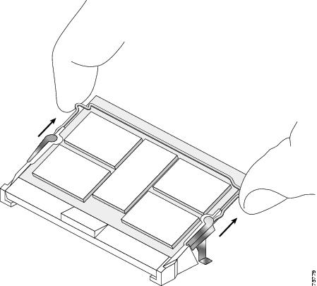
Step 8
Be sure that your index fingers are located on the outer corners of the SODIMM to maintain even pressure when the module is being seated in the socket.
Figure 32 Inserting a 144-pin SODIMM Module
Step 9
Caution
Step 10
Step 11
Step 12
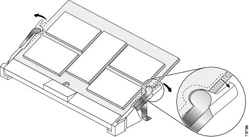
(See Figure 33.)Figure 33 Inserting the Retaining Clip
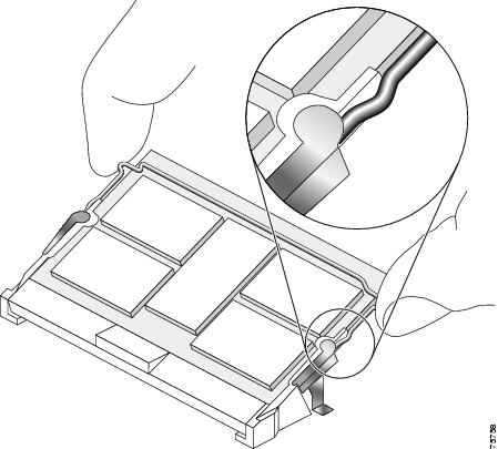
The clip is properly installed when the clip detente protrudes below the strain relief and plastic latch. (See Figure 34.)
Figure 34 Retaining Clip Completely Installed into Module Latch
Checking the Installation of Line Card Memory
After you install line card memory and reinstall the line card in the router, the router reinitializes the line card and detects the memory change as part of the reinitialization cycle. The time required for the router to initialize can vary with different router configurations and memory configurations.
If the line card does not reinitialize properly after you upgrade memory, or if the console terminal displays a checksum or memory error, verify that you installed the correct SODIMMs and that they are installed correctly on the line card.
To check the installation of line card memory, follow these steps:
Step 1
Step 2
If the router fails to restart properly after several attempts and you are unable to resolve the problem, access Cisco.com or contact your Cisco service representative for assistance. Before calling, however, make note of any console error messages, unusual LED states, or other router indications or behaviors that might help to resolve the problem.
Regulatory, Compliance, and Safety Information
This section includes regulatory, compliance, and safety information in the following sections:
•
•
Translated Safety Warnings and Agency Approvals
The complete list of translated safety warnings and agency approvals is available in the Regulatory Compliance and Safety Information for Cisco XR 12000 Series Routers publication.
(Document Number 78-4347-xx.)Electromagnetic Compatibility Regulatory Statements
This section contains the following information:
•
•
•
FCC Class A Compliance
This equipment has been tested and found to comply with the limits for a Class A digital device, pursuant to part 15 of the FCC rules. These limits are designed to provide reasonable protection against harmful interference when the equipment is operated in a commercial environment. This equipment generates, uses, and can radiate radio-frequency energy and, if not installed and used in accordance with the instruction manual, may cause harmful interference to radio communications. Operation of this equipment in a residential area is likely to cause harmful interference, in which case users will be required to correct the interference at their own expense.
Modifying the equipment without Cisco's authorization may result in the equipment no longer complying with FCC requirements for Class A digital devices. In that event, your right to use the equipment may be limited by FCC regulation and you may be required to correct any interference to radio or television communication at your own expense.
You can determine whether your equipment is causing interference by turning it off. If the interference stops, it was probably caused by the Cisco equipment or one of its peripheral devices. If the equipment causes interference to radio or television reception, try to correct the interference by using one or more of the following measures:
•
•
•
•
CISPR 22
This apparatus complies with CISPR 22/EN55022 Class B radiated and conducted emissions requirements.
Canada
English Statement of Compliance
This class A digital apparatus complies with Canadian ICES-003.
French Statement of Compliance
Cet appareil numérique de la classe A est conforme à la norme NMB-003 du Canada.
Europe (EU)
This apparatus complies with EN55022 Class B and EN55024 standards when used as ITE/TTE equipment, and EN300386 for Telecommunications Network Equipment (TNE) in both installation environments, telecommunication centers and other indoor locations.
Class A Notice for Hungary
VCCI Class A Notice for Japan
Class A Notice for Taiwan and Other Traditional Chinese Markets
VCCI Compliance for Class B Equipment
Class A Notice for Korea
Laser Safety
POS line cards are equipped with a Class 1 laser (VSR is Class 1M), which emits invisible radiation. Do not stare into operational line card ports. The following laser warnings apply to POS line cards:
•
•
Class 1 Laser Product Warning
The following warning applies to single-mode SR, IR, and LR optics:
Warning
Class 1M Laser Product Warnings (VSR Only)
The following warnings apply to line cards with VSR optics:
Warning
Warning
Warning
General Laser Warning
The following warning applies to all POS line cards:
Warning
For translated safety warnings, refer to the Regulatory Compliance and Safety Information for
Cisco 12000 Series Internet Routers publication (Document Number 78-4347-xx).Obtaining Documentation and Submitting a Service Request
For information on obtaining documentation, submitting a service request, and gathering additional information, see the monthly What's New in Cisco Product Documentation, which also lists all new and revised Cisco technical documentation, at:
http://www.cisco.com/en/US/docs/general/whatsnew/whatsnew.html
Subscribe to the What's New in Cisco Product Documentation as a Really Simple Syndication (RSS) feed and set content to be delivered directly to your desktop using a reader application. The RSS feeds are a free service and Cisco currently supports RSS Version 2.0.
This document is to be used in conjunction with the installation and configuration guide for your Cisco XR 12000 Series Router.
CCDE, CCENT, CCSI, Cisco Eos, Cisco HealthPresence, Cisco IronPort, the Cisco logo, Cisco Nurse Connect, Cisco Pulse, Cisco SensorBase, Cisco StackPower, Cisco StadiumVision, Cisco TelePresence, Cisco Unified Computing System, Cisco WebEx, DCE, Flip Channels, Flip for Good, Flip Mino, Flipshare (Design), Flip Ultra, Flip Video, Flip Video (Design), Instant Broadband, and Welcome to the Human Network are trademarks; Changing the Way We Work, Live, Play, and Learn, Cisco Capital, Cisco Capital (Design), Cisco:Financed (Stylized), Cisco Store, Flip Gift Card, and One Million Acts of Green are service marks; and Access Registrar, Aironet, AllTouch, AsyncOS, Bringing the Meeting To You, Catalyst, CCDA, CCDP, CCIE, CCIP, CCNA, CCNP, CCSP, CCVP, Cisco, the Cisco Certified Internetwork Expert logo, Cisco IOS, Cisco Lumin, Cisco Nexus, Cisco Press, Cisco Systems, Cisco Systems Capital, the Cisco Systems logo, Cisco Unity, Collaboration Without Limitation, Continuum, EtherFast, EtherSwitch, Event Center, Explorer, Follow Me Browsing, GainMaker, iLYNX, IOS, iPhone, IronPort, the IronPort logo, Laser Link, LightStream, Linksys, MeetingPlace, MeetingPlace Chime Sound, MGX, Networkers, Networking Academy, PCNow, PIX, PowerKEY, PowerPanels, PowerTV, PowerTV (Design), PowerVu, Prisma, ProConnect, ROSA, SenderBase, SMARTnet, Spectrum Expert, StackWise, WebEx, and the WebEx logo are registered trademarks of Cisco Systems, Inc. and/or its affiliates in the United States and certain other countries.
All other trademarks mentioned in this document or website are the property of their respective owners. The use of the word partner does not imply a partnership relationship between Cisco and any other company. (0910R)
Copyright © 2009 Cisco Systems, Inc. All rights reserved.


 Feedback
Contact Cisco
- Open a Support Case

- (Requires a Cisco Service Contract)