Multi-Service Blade (MSB) Installation
Available Languages
Table Of Contents
Multi-Service Blade (MSB) Installation
Preventing Electrostatic Discharge
Removing and Installing an MSB
Guidelines for MSB Removal and Installation
Verifying and Troubleshooting the MSB Installation
Troubleshooting the Installation
Displaying Diagnostic Information
Regulatory, Compliance, and Safety Information
Translated Safety Warnings and Agency Approvals
Regulatory Standards Compliance
Multi-Service Blade (MSB) Installation
December 15, 2006
Document Part Number: OL-11735-01, Rev. A0
This hardware installation note contains instructions for installing and troubleshooting the Multi-Service Blade (MSB) on supported Cisco XR 12000 Series Routers.
Contents
This installation and configuration guide includes the following sections:
•
Removing and Installing an MSB
•
•
•
Important Information
This section contains important information about the following:
MSB Product Numbers
This publication applies to the following products:
Router Hardware Installation
For hardware installation and configuration information for Cisco XR 12000 Series Routers, refer to the installation and configuration guide for your router. The guide includes information on the router switch fabric and how it affects operation of the line cards, as well as line card slot locations, slot width, and other requirements.
Also refer to the field-replaceable unit (FRU) publications that describe how to install, maintain, and replace router subsystems, such as cooling fans, power supplies, chassis backplanes, and so on.
Supported Platforms
The MSB is supported on all Cisco XR 12000 Series Routers.
Related Documentation
This publication describes the basic installation and initial configuration of the MSB. The following documents provide complementary information:
•
•
•
•
See the "Obtaining Documentation and Submitting a Service Request" section for information on how to obtain these publications.
See Cisco 12000 Series Routers Install and Upgrade Guides for information on router installation procedures.
MSB Overview
The MSB is a services card that provides the Cisco XR 12000 Series Router with a variety of edge services. The first service to be supported on the MSB as of Cisco IOS XR Release 3.4.0 is Session Border Controller (SBC). The alphanumeric LEDs provided an indication of the status of the card.
Figure 1 shows the front view of the card.
Figure 1 MSB Front Panel
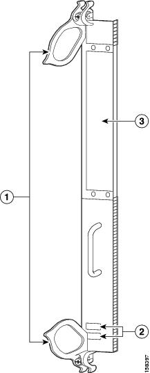
The MSB is shipped with a blank cover (XR-12K-MSB-BLANK) over the SPA subslot opening. Verify that the blank cover is in place before installing the MSB in the router.
Preparing for Installation
The following sections provide information about preparing to install the MSB:
•
Safety Guidelines
Before you perform any procedure in this publication, review the safety guidelines in this section to avoid injuring yourself or damaging the equipment.
The following guidelines are for your safety and to protect equipment. The guidelines do not include all hazards. Be alert.

Note
•
•
•
Preventing Electrostatic Discharge
Electrostatic discharge (ESD) damage, which can occur when electronic cards or components are improperly handled, results in complete or intermittent failures. Electromagnetic interference (EMI) shielding is an integral component of the line card. Cisco recommends using an ESD-preventive strap whenever you are handling network equipment or one of its components.
The following are guidelines for preventing ESD damage:
•
•
•
•

Caution
Required Tools and Equipment
You need the following tools and parts to remove and install MSBs:
•
•
Note
Removing and Installing an MSB
The following sections provide procedures for removing or installing an MSB:
•
Note
Guidelines for MSB Removal and Installation
Guidelines for MSB removal and installation include the following:
•
•
Caution
After removing and inserting a line card into the same slot, allow at least 60 seconds before removing or inserting another line card.
•
Caution
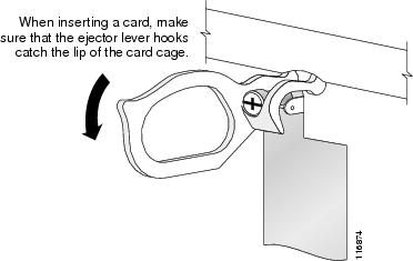
When you install an MSB, always use the ejector levers to ensure that the card is correctly aligned with the backplane connector; the connector pins should make contact with the backplane in the correct order, indicating that the card is fully seated in the backplane. If a card is only partially seated in the backplane, the router hangs and subsequently crashes.
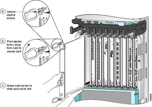
Removing an MSB
If you are replacing a failed MSB, remove the existing MSB first, then install the new MSB in the same slot. To remove an MSB, use Figure 2 as a reference and follow these steps:
Step 1
Step 2
Figure 2 Line Card Removal and Installation
Caution
Step 3
Step 4
Step 5
Step 6
Step 7
Installing an MSB
The MSB slides into almost any available line card slot and connects directly to the backplane. If you install a new MSB, you must first remove the line card blank from the available slot.
Note
Caution
To install the MSB, follow these steps:
Step 1
Step 2
Caution
Step 3
Step 4
Figure 3 Ejector Levers
Caution
Step 5
Step 6
Caution
For information on verifying and troubleshooting the hardware installation, see the "Verifying and Troubleshooting the MSB Installation" section.
Verifying and Troubleshooting the MSB Installation
The following sections describe how to verify and troubleshoot the MSB installation:
•
•
Initial Boot Process
During a typical MSB boot process, the following events occur:
1.
2.
3.
To verify that the MSB is working properly, perform the following operational check:
•
If this condition is not met, refer to Troubleshooting the Installation to identify any possible problems.
Alphanumeric LED Descriptions
The MSB includes an alphanumeric LED display consisting of four characters arranged in two rows (upper and lower). In general, the LEDs do not come on until the RP recognizes and powers up the card. As it boots, the line card displays a sequence of messages. Table 1 lists the alphanumeric LED messages that may appear on the MSB.
Troubleshooting the Installation
The following sections provide MSB troubleshooting information:
•
Displaying Diagnostic Information
The show diags command can be used to indicate the status of a newly installed MSB. It indicates the ROMMON version, the fabric loader version, and the DRAM size, among other things. In the following example, this information is indicated in bold:
RP/0/0/CPU0:router# show diags 0/3/CPU0SLOT 3 (RP/LC 3): Cisco 12000 Series - Service Engine CardMAIN: type 150, 800-25972-01 rev @6 dev 0HW config: 0x00 SW key: 00-00-00PCA: 73-9289-03 rev 81 ver 2HW version 1.0 S/N SAD10330584MBUS: Embedded AgentTest hist: 0x00 RMA#: 00-00-00 RMA hist: 0x00DIAG: Test count: 0x00000000 Test results: 0x00000000FRU: Linecard/Module: 12000-ServEngCardL3 Engine: Service Engine - ISE OC192 (10 Gbps)MBUS Agent Software version 2.49 (RAM) (ROM version is 3.3)Using CAN Bus AROM Monitor version 1.2Fabric Downloader version used 1.4 (ROM version is 1.3)Primary clock is CSC1Board State is IOS-XR RUNInsertion time: Mon Sep 11 22:44:35 2006 (01:36:23 ago)DRAM size: 2147483648 bytesFrFab SDRAM size: 1610612736 bytesToFab SDRAM size: 268435456 bytes0 crashes since restart/fault forgiveUpgrading the FPD Version
You must upgrade the field-programmable device (FPD) images on your MSB in the following instances:
•
•
•
If there is an FPD incompatibility with your MSB, you may receive an error message. To resolve this issue, you must upgrade the FPD image on your card. Use the upgrade hw-module fpd command. For more information, see "Upgrading FPD Images on Cisco IOS XR Software" in Cisco IOS XR Interface and Hardware Component Configuration Guide.
Regulatory, Compliance, and Safety Information
This section includes regulatory, compliance, and safety information in the following sections:
•
•
Translated Safety Warnings and Agency Approvals
The complete list of translated safety warnings and agency approvals is available in the Regulatory Compliance and Safety Information for Cisco XR 12000 Series Routers publication.
(Document Number 78-4347-xx.)Regulatory Standards Compliance
MSB complies with the national and international standards listed in Table 2.
Obtaining Documentation and Submitting a Service RequestFor information on obtaining documentation, submitting a service request, and gathering additional information, see the monthly What's New in Cisco Product Documentation, which also lists all new and revised Cisco technical documentation, at:
http://www.cisco.com/en/US/docs/general/whatsnew/whatsnew.html
Subscribe to the What's New in Cisco Product Documentation as a Really Simple Syndication (RSS) feed and set content to be delivered directly to your desktop using a reader application. The RSS feeds are a free service and Cisco currently supports RSS version 2.0.
This document is to be used in conjunction with the installation and configuration guide for your Cisco XR 12000 Series Router.
CCDE, CCENT, Cisco Eos, Cisco Lumin, Cisco Nexus, Cisco StadiumVision, the Cisco logo, DCE, and Welcome to the Human Network are trademarks; Changing the Way We Work, Live, Play, and Learn is a service mark; and Access Registrar, Aironet, AsyncOS, Bringing the Meeting To You, Catalyst, CCDA, CCDP, CCIE, CCIP, CCNA, CCNP, CCSP, CCVP, Cisco, the Cisco Certified Internetwork Expert logo, Cisco IOS, Cisco Press, Cisco Systems, Cisco Systems Capital, the Cisco Systems logo, Cisco Unity, Collaboration Without Limitation, EtherFast, EtherSwitch, Event Center, Fast Step, Follow Me Browsing, FormShare, GigaDrive, HomeLink, Internet Quotient, IOS, iPhone, iQ Expertise, the iQ logo, iQ Net Readiness Scorecard, iQuick Study, IronPort, the IronPort logo, LightStream, Linksys, MediaTone, MeetingPlace, MGX, Networkers, Networking Academy, Network Registrar, PCNow, PIX, PowerPanels, ProConnect, ScriptShare, SenderBase, SMARTnet, Spectrum Expert, StackWise, The Fastest Way to Increase Your Internet Quotient, TransPath, WebEx, and the WebEx logo are registered trademarks of Cisco Systems, Inc. and/or its affiliates in the United States and certain other countries.
All other trademarks mentioned in this document or Website are the property of their respective owners. The use of the word partner does not imply a partnership relationship between Cisco and any other company. (0805R)
Copyright © 2008 Cisco Systems, Inc. All rights reserved.
 Feedback
Contact Cisco
- Open a Support Case

- (Requires a Cisco Service Contract)