- Preface
- New and Changed Information in Release 5.1.x
- Implementing MPLS Layer 2 VPNs
- Implementing IPv6 VPN Provider Edge Transport over MPLS
- Implementing Virtual Private LAN Services
- Implementing Layer 2 Tunnel Protocol Version 3
- Implementing MPLS VPNs over IP Tunnels
- Implementing MPLS Layer 3 VPNs
- Index
- Contents
- Prerequisites for Implementing MPLS L2VPN
- Information About Implementing L2VPN
- L2VPN Overview
- ATMoMPLS with L2VPN Capability
- Virtual Circuit Connection Verification on L2VPN
- Ethernet over MPLS
- Quality of Service
- High Availability
- Preferred Tunnel Path
- Any Transport over MPLS
- ATM AAL5 to Ethernet Bridged Interworking
- Ethernet or Bridged Interworking
- Circuit Emulation Over Packet Switched Network
- L2VPN Nonstop Routing
- Pseudowire Grouping
- How to Implement L2VPN
- Configuring an Interface or Connection for L2VPN
- Configuring Static Point-to-Point Cross-Connects
- Configuring Dynamic Point-to-Point Cross-Connects
- Configuring Inter-AS
- Configuring L2VPN Quality of Service
- Configuring Preferred Tunnel Path
- Configuring AToM IP Interworking
- Configuring Ethernet ACs for AToM IP Interworking
- Configuring Frame Relay ACs for AToM IP Interworking
- Configuring ATM AAL5 ACs for AToM IP Interworking
- Configuring PPP ACs for AToM IP Interworking
- Configuring Local Switching on PPP ACs
- Configuring IP Interworking on PPP ACs
- Configuring cHDLC ACs for AToM IP Interworking
- Configuring Local Switching on cHDLC ACs
- Configuring IP Interworking on cHDLC ACs
- Configuring Frame Relay AC for Bridged Interworking
- Configuring Pseudowire Class
- Configuring Circuit Emulation Over Packet Switched Network
- Configuring L2VPN Nonstop Routing
- Enabling Pseudowire Grouping
- Configuration Examples for L2VPN
- L2VPN Interface Configuration: Example
- Point-to-Point Cross-connect Configuration: Examples
- Inter-AS: Example
- L2VPN Quality of Service: Example
- Preferred Path: Example
- AToM IP Interworking: Examples
- Bridged Interworking: Example
- ATM AAL5 to Ethernet Bridged Interworking: Example
- AToM Cross Connect Configuration: Example
- Configuring L2VPN over GRE Tunnels: Example
- Configuring Circuit Emulation Over Packet Switched Network: Example
- Configuring L2VPN Nonstop Routing: Example
- Enabling Pseudowire Grouping: Example
- Additional References
Implementing MPLS Layer 2 VPNs
This module provides the conceptual and configuration information for MPLS Layer 2 virtual private networks (VPNs) on Cisco IOS XR software.
For the functionality of MPLS VPNs over IP Tunnels, see Implementing MPLS VPNs over IP Tunnels in Cisco IOS XR Virtual Private Network Configuration Guide.

Note ![]() For more information about MPLS Layer 2 VPN on the Cisco IOS XR software and for descriptions of the commands listed in this module, see the "Related Documents" section. To locate documentation for other commands that might appear while executing a configuration task, search online in the Cisco IOS XR software master command index.
For more information about MPLS Layer 2 VPN on the Cisco IOS XR software and for descriptions of the commands listed in this module, see the "Related Documents" section. To locate documentation for other commands that might appear while executing a configuration task, search online in the Cisco IOS XR software master command index.
Feature History for Implementing MPLS Layer 2 VPN Configuration Module
Contents
•![]() Prerequisites for Implementing MPLS L2VPN
Prerequisites for Implementing MPLS L2VPN
•![]() Information About Implementing L2VPN
Information About Implementing L2VPN
•![]() Configuration Examples for L2VPN
Configuration Examples for L2VPN
Prerequisites for Implementing MPLS L2VPN
To perform these configuration tasks, your Cisco IOS XR software system administrator must assign you to a user group associated with a task group that includes the corresponding command task IDs. All command task IDs are listed in individual command references and in the Cisco IOS XR Task ID Reference Guide.
If you need assistance with your task group assignment, contact your system administrator.
Information About Implementing L2VPN
To implement MPLS L2VPN, you should understand the following concepts:
•![]() ATMoMPLS with L2VPN Capability
ATMoMPLS with L2VPN Capability
•![]() Virtual Circuit Connection Verification on L2VPN
Virtual Circuit Connection Verification on L2VPN
•![]() Circuit Emulation Over Packet Switched Network
Circuit Emulation Over Packet Switched Network
L2VPN Overview
Layer 2 VPN (L2VPN) emulates the behavior of a LAN across an IP or MPLS-enabled IP network allowing Ethernet devices to communicate with each other as they would when connected to a common LAN segment.
As Internet service providers (ISPs) look to replace Frame Relay or their Asynchronous Transfer Mode (ATM) infrastructures with an IP infrastructure, there is a need for to provide standard methods of using an IP infrastructure to provide a serviceable L2 interface to customers; specifically, to provide standard ways of using an IP infrastructure to provide virtual circuits between pairs of customer sites.
Building a L2VPN system requires coordination between the ISP and the customer. The ISP provides L2 connectivity; the customer builds a network using data link resources obtained from the ISP. In an L2VPN service, the ISP does not require information about a the customer's network topology, policies, routing information, point-to-point links, or network point-to-point links from other ISPs.
The ISP requires provider edge (PE) routers with the following capabilities:
•![]() Encapsulation of L2 protocol data units (PDU) into Layer 3 (L3) packets.
Encapsulation of L2 protocol data units (PDU) into Layer 3 (L3) packets.
•![]() Interconnection of any-to-any L2 transports.
Interconnection of any-to-any L2 transports.
•![]() Emulation of L2 quality-of-service (QoS) over a packet switch network.
Emulation of L2 quality-of-service (QoS) over a packet switch network.
•![]() Ease of configuration of the L2 service.
Ease of configuration of the L2 service.
•![]() Support for different types of tunneling mechanisms (MPLS, L2TPv3, IPSec, GRE, and others).
Support for different types of tunneling mechanisms (MPLS, L2TPv3, IPSec, GRE, and others).
•![]() L2VPN process databases include all information related to circuits and their connections.
L2VPN process databases include all information related to circuits and their connections.
ATMoMPLS with L2VPN Capability
These topics describe the ATM over MPLS (ATMoMPLS) with L2VPN feature:
•![]() Layer 2 Local Switching Overview
Layer 2 Local Switching Overview
ATMoMPLS with L2VPN Overview
The ATMoMPLS feature supports ATM Adaptation Layer 5 (AAL5) transport. ATMoMPLS is a type of Layer 2 point-to-point connection over an MPLS core. ATMoMPLS and ATM local switching are supported only for ATM-to-ATM interface-to-interface switching combinations.
To implement the ATMoMPLS feature, the Cisco CRS-1 router plays the role of provider edge (PE) router at the edge of a provider network in which customer edge (CE) devices are connected to the Cisco CRS-1 routers.
Layer 2 Local Switching Overview
Local switching lets you to switch Layer 2 data between two interfaces of the same type (for example, ATM-to-ATM, or Frame Relay-to-Frame Relay) or between interfaces of different types (for example, Frame Relay to ATM) on the same router, over an IP core network. The interfaces are on the same line card or on two different cards. During these types of switching, Layer 2 address is used instead of the Layer 3 address.
In addition, same-port local switching lets you to switch Layer 2 data between two circuits on the same interface.
ATM Adaptation Layer 5
AAL5 lets you transport AAL5 PDUs from various customers over an MPLS backbone. ATM AAL5 extends the usability of the MPLS backbone by enabling it to offer Layer 2 services in addition to already existing Layer 3 services. You can enable the MPLS backbone network to accept AAL5 PDUs by configuring the provider edge (PE) routers at both ends of the MPLS backbone.
To transport AAL5 PDUs over MPLS, a virtual circuit is set up from the ingress PE router to the egress PE router. This virtual circuit transports the AAL5 PDUs from one PE router to the other. Each AAL5 PDU is transported as a single packet.
Virtual Circuit Connection Verification on L2VPN
Virtual Circuit Connection Verification (VCCV) is an L2VPN Operations, Administration, and Maintenance (OAM) feature that allows network operators to run IP-based provider edge-to-provider edge (PE-to-PE) keepalive protocol across a specified pseudowire to ensure that the pseudowire data path forwarding does not contain any faults. The disposition PE receives VCCV packets on a control channel, which is associated with the specified pseudowire. The control channel type and connectivity verification type, which are used for VCCV, are negotiated when the pseudowire is established between the PEs for each direction.
Two types of packets can arrive at the disposition egress:
•![]() Type 1—Specifies normal Ethernet-over-MPLS (EoMPLS) data packets.
Type 1—Specifies normal Ethernet-over-MPLS (EoMPLS) data packets.
•![]() Type 2—Specifies VCCV packets.
Type 2—Specifies VCCV packets.
Cisco IOS XR software supports Label Switched Path (LSP) VCCV Type 1, which uses an inband control word if enabled during signaling. The VCCV echo reply is sent as IPv4 that is the reply mode in IPv4. The reply is forwarded as IP, MPLS, or a combination of both.
VCCV pings counters that are counted in MPLS forwarding on the egress side. However, on the ingress side, they are sourced by the route processor and do not count as MPLS forwarding counters.
Ethernet over MPLS
Ethernet-over-MPLS (EoMPLS) provides a tunneling mechanism for Ethernet traffic through an MPLS-enabled L3 core and encapsulates Ethernet protocol data units (PDUs) inside MPLS packets (using label stacking) to forward them across the MPLS network.
EoMPLS features are described in the following subsections:
•![]() Mac-in-Mac Protocol (Provide Backbone Bridging)
Mac-in-Mac Protocol (Provide Backbone Bridging)
Ethernet Port Mode
In Ethernet port mode, both ends of a pseudowire are connected to Ethernet ports. In this mode, the port is tunneled over the pseudowire or, using local switching (also known as an attachment circuit-to-attachment circuit cross-connect) switches packets or frames from one attachment circuit (AC) to another AC attached to the same PE node.
Note ![]() L2VPN forwarding using GRE tunnels is supported in the Ethernet port mode.
L2VPN forwarding using GRE tunnels is supported in the Ethernet port mode.
Figure 1 provides an example of Ethernet port mode.
Figure 1 Ethernet Port Mode Packet Flow
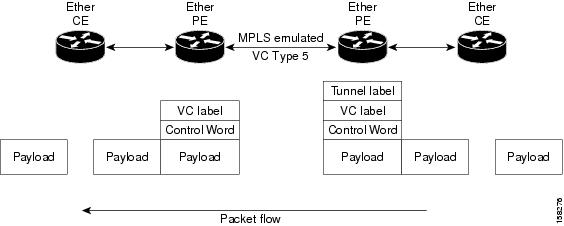
VLAN Mode
In VLAN mode, each VLAN on a customer-end to provider-end link can be configured as a separate L2VPN connection using virtual connection (VC) type 4 or VC type 5. VC type 4 is the default mode.
As illustrated in Figure 2, the Ethernet PE associates an internal VLAN-tag to the Ethernet port for switching the traffic internally from the ingress port to the pseudowire; however, before moving traffic into the pseudowire, it removes the internal VLAN tag.
Figure 2 VLAN Mode Packet Flow
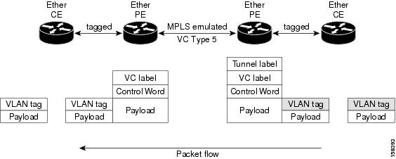
At the egress VLAN PE, the PE associates a VLAN tag to the frames coming off of the pseudowire and after switching the traffic internally, it sends out the traffic on an Ethernet trunk port.
Note ![]() Because the port is in trunk mode, the VLAN PE doesn't remove the VLAN tag and forwards the frames through the port with the added tag.
Because the port is in trunk mode, the VLAN PE doesn't remove the VLAN tag and forwards the frames through the port with the added tag.
Note ![]() L2VPN forwarding using GRE tunnels is supported in the VLAN mode.
L2VPN forwarding using GRE tunnels is supported in the VLAN mode.
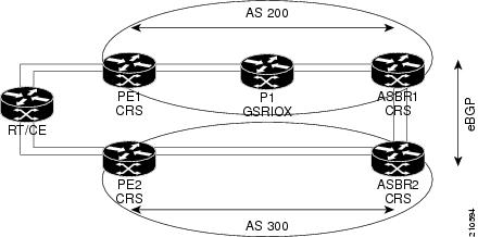
Inter-AS Mode
Inter-AS is a peer-to-peer type model that allows extension of VPNs through multiple provider or multi-domain networks. This lets service providers peer up with one another to offer end-to-end VPN connectivity over extended geographical locations.
EoMPLS support can assume a single AS topology where the pseudowire connecting the PE routers at the two ends of the point-to-point EoMPLS cross-connects resides in the same autonomous system; or multiple AS topologies in which PE routers can reside on two different ASs using iBGP and eBGP peering.
Figure 3 illustrates MPLS over Inter-AS with a basic double AS topology with iBGP/LDP in each AS.
Figure 3 EoMPLS over Inter-AS: Basic Double AS Topology
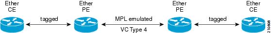
QinQ Mode
QinQ is an extension of 802.1Q for specifying multiple 802.1Q tags (IEEE 802.1QinQ VLAN Tag stacking). Layer 3 VPN service termination and L2VPN service transport are enabled over QinQ sub-interfaces.
The Cisco CRS-1 router implements the Layer 2 tunneling or Layer 3 forwarding depending on the subinterface configuration at provider edge routers. This function only supports up to two QinQ tags on the SPA and fixed PLIM:
•![]() Layer 2 QinQ VLANs in L2VPN attachment circuit: QinQ L2VPN attachment circuits are configured under the Layer 2 transport subinterfaces for point-to-point EoMPLS based cross-connects using both virtual circuit type 4 and type 5 pseudowires and point-to-point local-switching-based cross-connects including full interworking support of QinQ with 802.1q VLANs and port mode.
Layer 2 QinQ VLANs in L2VPN attachment circuit: QinQ L2VPN attachment circuits are configured under the Layer 2 transport subinterfaces for point-to-point EoMPLS based cross-connects using both virtual circuit type 4 and type 5 pseudowires and point-to-point local-switching-based cross-connects including full interworking support of QinQ with 802.1q VLANs and port mode.
•![]() Layer 3 QinQ VLANs: Used as a Layer 3 termination point, both VLANs are removed at the ingress provider edge and added back at the remote provider edge as the frame is forwarded.
Layer 3 QinQ VLANs: Used as a Layer 3 termination point, both VLANs are removed at the ingress provider edge and added back at the remote provider edge as the frame is forwarded.
Layer 3 services over QinQ include:
•![]() IPv4 unicast and multicast
IPv4 unicast and multicast
•![]() IPv6 unicast and multicast
IPv6 unicast and multicast
•![]() MPLS
MPLS
•![]() Connectionless Network Service (CLNS) for use by Intermediate System-to-Intermediate System (IS-IS) Protocol
Connectionless Network Service (CLNS) for use by Intermediate System-to-Intermediate System (IS-IS) Protocol
Note ![]() The Cisco CRS-1 router does not support: bundle attachment circuits and Hot Standby Router Protocol (HSRP) or Virtual Router Redundancy Protocol (VRRP) on QinQ subinterfaces.
The Cisco CRS-1 router does not support: bundle attachment circuits and Hot Standby Router Protocol (HSRP) or Virtual Router Redundancy Protocol (VRRP) on QinQ subinterfaces.
In QinQ mode, each CE VLAN is carried into an SP VLAN. QinQ mode should use VC type 5, but VC type 4 is also supported. On each Ethernet PE, you must configure both the inner (CE VLAN) and outer (SP VLAN).
Figure 4 illustrates QinQ using VC type 4.
Figure 4 EoMPLS over QinQ Mode
QinAny Mode
In the QinAny mode, the service provider VLAN tag is configured on both the ingress and the egress nodes of the provider edge VLAN. QinAny mode is similar to QinQ mode using a Type 5 VC, except that the customer edge VLAN tag is carried in the packet over the pseudowire, as the customer edge VLAN tag is unknown.
Mac-in-Mac Protocol (Provide Backbone Bridging)
The Mac-in-Mac (or, Provider Backbone Bridging) protocol lets service providers scale networks using Ethernet technology to maintain management and operational simplicity, and reduce operating costs.
Mac-In-Mac encapsulates the customer MAC header with a service provider MAC header. Instead of using additional Q-tags to separate end customers, a 24-bit service tag in the service provider encapsulating MAC header is used, which provides support for up to 16-million service instances.
Note ![]() Mac-In-Mac is standardized as IEEE 802.1ah.
Mac-In-Mac is standardized as IEEE 802.1ah.
Quality of Service
Using L2VPN technology, you can assign a quality of service (QoS) level to both Port and VLAN modes of operation.
L2VPN technology requires that QoS functionality on PE routers be strictly L2-payload-based on the edge-facing interfaces (also know as attachment circuits). Figure 5 illustrates L2 and L3 QoS service policies in a typical L2VPN network.
Figure 5 L2VPN QoS Feature Application
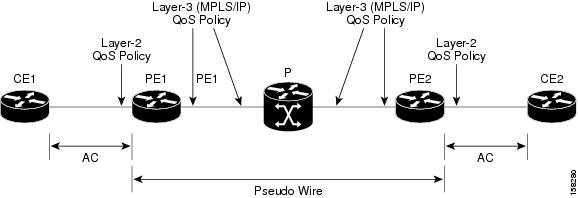
Figure 6 shows four packet processing paths within a provider edge device where a QoS service policy can be attached. In an L2VPN network, packets are received and transmitted on the edge-facing interfaces as L2 packets and transported on the core-facing interfaces as MPLS (EoMPLS) or IP (L2TP) packets.
Figure 6 L2VPN QoS Reference Model

High Availability
L2VPN uses control planes in both route processors and line cards, as well as forwarding plane elements in the line cards.
Note ![]() The l2tp_mgr process does not support high availability.
The l2tp_mgr process does not support high availability.
The availability of L2VPN meets the following requirements:
•![]() A control plane failure in either the route processor or the line card will not affect the circuit forwarding path.
A control plane failure in either the route processor or the line card will not affect the circuit forwarding path.
•![]() The router processor control plane supports failover without affecting the line card control and forwarding planes.
The router processor control plane supports failover without affecting the line card control and forwarding planes.
•![]() L2VPN integrates with existing Label Distribution Protocol (LDP) graceful restart mechanism.
L2VPN integrates with existing Label Distribution Protocol (LDP) graceful restart mechanism.
Preferred Tunnel Path
Preferred tunnel path functionality lets you map pseudowires to specific traffic-engineering tunnels. Attachment circuits are cross-connected to specific MPLS traffic engineering tunnel interfaces instead of remote PE router IP addresses (reachable using IGP or LDP). Using preferred tunnel path, it is always assumed that the traffic engineering tunnel that transports the L2 traffic runs between the two PE routers (that is, its head starts at the imposition PE router and its tail terminates on the disposition PE router).
Note![]() •
•![]() Currently, preferred tunnel path configuration applies only to MPLS encapsulation.
Currently, preferred tunnel path configuration applies only to MPLS encapsulation.
•![]() The fallback enable option is supported.
The fallback enable option is supported.
Any Transport over MPLS
Any Transport over MPLS (AToM) transports Layer 2 packets over a Multiprotocol Label Switching (MPLS) backbone, which enables service providers to connect customer sites with existing Layer 2 networks by using a single, integrated, packet-based network infrastructure. Using this feature, service providers can deliver Layer 2 connections over an MPLS backbone, instead of using separate networks.
AToM encapsulates Layer 2 frames at the ingress PE router and sends them to a corresponding PE router at the other end of a pseudowire, which is a connection between the two PE routers. The egress PE removes the encapsulation and sends out the Layer 2 frame.
The successful transmission of the Layer 2 frames between PE routers is due to the configuration of the PE routers. You set up the connection, called a pseudowire, between the routers. You specify the following information on each PE router:
•![]() The type of Layer 2 data that will be transported across the pseudowire, such as Ethernet, Frame Relay, or ATM
The type of Layer 2 data that will be transported across the pseudowire, such as Ethernet, Frame Relay, or ATM
•![]() The IP address of the loopback interface of the peer PE router, which enables the PE routers to communicate
The IP address of the loopback interface of the peer PE router, which enables the PE routers to communicate
•![]() A unique combination of peer PE IP address and VC ID that identifies the pseudowire
A unique combination of peer PE IP address and VC ID that identifies the pseudowire
These topics describe the AToM feature:
IP or Routed Interworking
In AToM IP Interworking, also called routed interworking, the carrier edge (CE) routers encapsulate IP on the link between the CE and PE routers. A new VC type is used to signal the IP pseudowire in MPLS and L2TPv3. Translation between the Layer 2 and IP encapsulations across the pseudowire is required.
IP Interworking is used to provide IP connectivity between sites, regardless of the Layer 2 connectivity to these sites. It is different from a Layer 3 VPN, because it is point-to-point in nature and the service provider does not maintain any customer routing information.
These modes support IP Interworking on AToM:
•![]() ATM to Ethernet: In this interworking, both ATM and Ethernet PE routers are configured for IP interworking. IP packets from an ATM CE are encapsulated using IP over MPLS and transmitted over the pseudowire. On the Ethernet side, the Ethernet PE removes the Layer 2 framing on the Ethernet packets from the Ethernet CE and forwards the IP packet on the pseudowire using IP over MPLS encapsulation. Non-IP packets are dropped in this process. At the ATM PE, after label disposition, the IP packets are encapsulated over AAL5 using IP encapsulation. In either direction, packets for which translations are not supported, are dropped.
ATM to Ethernet: In this interworking, both ATM and Ethernet PE routers are configured for IP interworking. IP packets from an ATM CE are encapsulated using IP over MPLS and transmitted over the pseudowire. On the Ethernet side, the Ethernet PE removes the Layer 2 framing on the Ethernet packets from the Ethernet CE and forwards the IP packet on the pseudowire using IP over MPLS encapsulation. Non-IP packets are dropped in this process. At the ATM PE, after label disposition, the IP packets are encapsulated over AAL5 using IP encapsulation. In either direction, packets for which translations are not supported, are dropped.
•![]() Ethernet port to VLAN mode: Using the Ethernet port mode, you can create an Ethernet virtual local area network (VLAN) among geographically separated sites. Different sites can operate together over an MPLS network as though they were on a common Ethernet network.
Ethernet port to VLAN mode: Using the Ethernet port mode, you can create an Ethernet virtual local area network (VLAN) among geographically separated sites. Different sites can operate together over an MPLS network as though they were on a common Ethernet network.
•![]() Frame Relay to Ethernet: Multi-protocol Frame Relay packets from the Frame Relay CE are encapsulated using IP over MPLS and transmitted over the pseudowire. On the Ethernet side, the Ethernet PE removes the Layer 2 framing on the Ethernet packets from the Ethernet CE and forwards the Layer 3 packet over the pseudowire using IP over MPLS encapsulation. At the Frame Relay PE, after label disposition, the Layer 3 packets are encapsulated over Frame Relay using IP encapsulation. In either direction, packets for which translations are not supported are dropped.
Frame Relay to Ethernet: Multi-protocol Frame Relay packets from the Frame Relay CE are encapsulated using IP over MPLS and transmitted over the pseudowire. On the Ethernet side, the Ethernet PE removes the Layer 2 framing on the Ethernet packets from the Ethernet CE and forwards the Layer 3 packet over the pseudowire using IP over MPLS encapsulation. At the Frame Relay PE, after label disposition, the Layer 3 packets are encapsulated over Frame Relay using IP encapsulation. In either direction, packets for which translations are not supported are dropped.
•![]() Frame Relay to ATM AAL5: ATM and Frame Relay links are locally terminated and IP interworking is used to transport the Layer 3 packets over the IP over MPLS pseudowire.
Frame Relay to ATM AAL5: ATM and Frame Relay links are locally terminated and IP interworking is used to transport the Layer 3 packets over the IP over MPLS pseudowire.
•![]() ATM AAL5—ATM Adaptation Layer Type-5 (AAL5) allows efficient transportation of PVCs across the MPLS backbone. Multiple PVCs can be multiplexed onto a single label switched path between the provider edge routers.
ATM AAL5—ATM Adaptation Layer Type-5 (AAL5) allows efficient transportation of PVCs across the MPLS backbone. Multiple PVCs can be multiplexed onto a single label switched path between the provider edge routers.
•![]() Point-to-Point—In this interworking, the point-to-point protocol (PPP) session is terminated at the PE while interworking with PPP attachment circuits. The PE router is responsible for negotiating LCP and IPCP with the CE router. PPP on the PE router can be configured with the ppp ipcp address proxy ip-address command where the remote CE router's IP address is used. This IP address is used by the PE router during IPCP negotiations with the CE router.
Point-to-Point—In this interworking, the point-to-point protocol (PPP) session is terminated at the PE while interworking with PPP attachment circuits. The PE router is responsible for negotiating LCP and IPCP with the CE router. PPP on the PE router can be configured with the ppp ipcp address proxy ip-address command where the remote CE router's IP address is used. This IP address is used by the PE router during IPCP negotiations with the CE router.
•![]() Cisco High-Level Data Link Control (cHDLC)—Interworking with cHDLC attachment circuits works in the same way as interworking with PPP attachment circuits. However, keepalive messages are sent and received between the PE and CE routers to keep the L2VPN attachment circuit active.
Cisco High-Level Data Link Control (cHDLC)—Interworking with cHDLC attachment circuits works in the same way as interworking with PPP attachment circuits. However, keepalive messages are sent and received between the PE and CE routers to keep the L2VPN attachment circuit active.
These types of cross connections are supported for AToM IP Interworking:
•![]() Ethernet
Ethernet
–![]() VLAN
VLAN
–![]() Q-in-Q
Q-in-Q
–![]() Frame Relay
Frame Relay
–![]() ATM AAL5 SNAP/MUX/NLPID
ATM AAL5 SNAP/MUX/NLPID
•![]() VLAN
VLAN
–![]() Ethernet
Ethernet
–![]() Q-in-Q
Q-in-Q
–![]() Frame Relay
Frame Relay
–![]() ATM AAL5 SNALP/MUX/NLPID
ATM AAL5 SNALP/MUX/NLPID
•![]() Q-in-Q
Q-in-Q
–![]() Ethernet
Ethernet
–![]() VLAN
VLAN
–![]() Frame Relay
Frame Relay
–![]() ATM AAL5 SNAP/MUX/NLPID
ATM AAL5 SNAP/MUX/NLPID
•![]() Frame Relay
Frame Relay
–![]() Ethernet
Ethernet
–![]() VLAN
VLAN
–![]() Q-in-Q
Q-in-Q
–![]() ATM AAL5 SNAP/MUX/NLPID
ATM AAL5 SNAP/MUX/NLPID
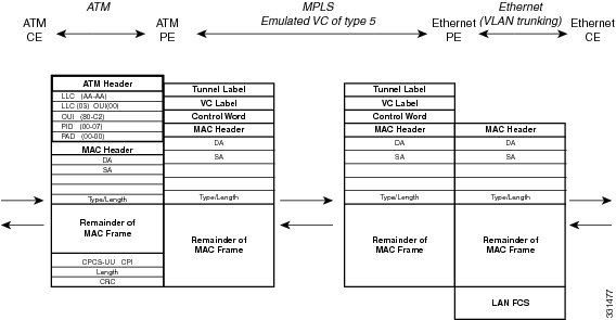
ATM AAL5 to Ethernet Bridged Interworking
This interworking provides interoperability between ATM attachment virtual circuit (AC) and Ethernet attachment AC connected to different provider edge (PE) routers. The bridged encapsulation is used corresponding to the bridged (Ethernet) interworking mechanism.
The interworking function is performed at the PE connected to the ATM AC.
Processing at PE connected to ATM AC
In the direction from the ATM segment to MPLS cloud, the bridged encapsulation (ATM or SNAP header) is discarded and the ethernet frame is encapsulated with the labels required to pass through the pseudowire using the VC type 5 (Ethernet). ATM side is configured with encapsulation type as aal5snap. In the opposite direction, after the label disposition from the MPLS cloud, ethernet frames are encapsulated over AAL5 using bridged encapsulation.
These translations are supported:
•![]() Ethernet without LAN FCS
Ethernet without LAN FCS
•![]() Spanning tree
Spanning tree
The existing QoS functionality for ATM is supported, including setting the ATM CLP bit. Non-AAL5 traffic, (e.g. OAM cells) are processed at RP level. A VC that has been configured with OAM cell emulation on the ATM PE router (with oam-ac emulation-enable command) can send end-to-end F5 loopback cells at configured intervals toward the customer edge (CE) router. When the pseudowire is down, an F5 end-to-end segment alarm indication signal or remote defect indication (AIS/RD) is sent from the PE router to the CE router.
Restrictions
These restrictions must be considered:
•![]() Only ATM AAL5 VC mode is supported. ATM VP and port mode are not supported.
Only ATM AAL5 VC mode is supported. ATM VP and port mode are not supported.
•![]() SVCs are not supported.
SVCs are not supported.
Processing at PE connected to Ethernet AC
This section provides information on:
Ethernet Port Mode
The Ethernet PE (connected to the Ethernet segment) operates similarly to Ethernet like-to-like services. For the packets coming from MPLS cloud, after the label disposition, the Ethernet frames are sent as is towards CE.
Figure 7 Protocol Stack for ATM to Ethernet AToM Bridged Interworking (without VLAN tag)
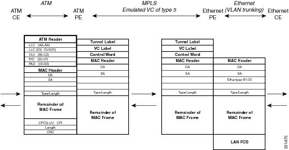
Note ![]() If the Ethernet frame arriving from Ethernet CE includes a 802.1Q header (VLAN header), due to the type of endpoint attachment (Ethernet port mode), the VLAN header stays in the frame across the pseudowire as shown in Figure 8.
If the Ethernet frame arriving from Ethernet CE includes a 802.1Q header (VLAN header), due to the type of endpoint attachment (Ethernet port mode), the VLAN header stays in the frame across the pseudowire as shown in Figure 8.
Figure 8 Protocol Stack for ATM to Ethernet AToM Bridged Interworking (with Vlan tag)

Ethernet dot1q/qinq
The PE connected to the Ethernet side discards the VLAN tags present in the incoming packets from the VLAN CE and pushed towards the MPLS cloud. For packets coming from MPLS cloud, it inserts VLAN tags into the Ethernet frames. Therefore, the frames sent on the pseudo wire (with VC type 5) are Ethernet frames without the VLAN header.
Note ![]() Ethernet frames received from the VLAN CE can contain more than two tags. Therefore, the number of tags processed or removed on the PE depends on the encapsulation type (dot1q/qinq) and the remaining tags are sent towards MPLS cloud as the payload.
Ethernet frames received from the VLAN CE can contain more than two tags. Therefore, the number of tags processed or removed on the PE depends on the encapsulation type (dot1q/qinq) and the remaining tags are sent towards MPLS cloud as the payload.
Figure 9 Protocol Stack for ATM to VLAN AToM Bridged Interworking
Local Switching
The functionality mentioned in the earlier sections applies to Local switching as well. The only difference is that, no PWE3 signaling is involved in bringing up the L2VPN circuit.
Ethernet or Bridged Interworking
Ethernet interworking is also called bridged interworking. Ethernet frames are bridged across the pseudowire. The CE routers could be natively bridging Ethernet or could be routing using a bridged encapsulation model. The PE routers operate in Ethernet like-to-like mode.
Figure 10 shows the reference network for Frame Relay (FR) to Ethernet bridged interworking.
Figure 10 Reference Network for Bridged Interworking
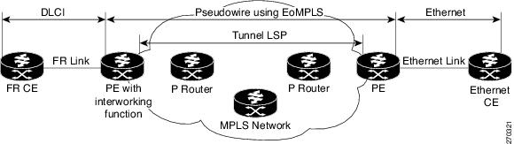
On the PE connected to FR attachment circuit (AC), in the direction from the FR segment to MPLS cloud, the Ethernet frames are received with the Frame Relay bridged encapsulation (FR/SNAP header). The SNAP header is discarded and the Ethernet frame is encapsulated with the labels required to pass through the pseudowire using the VC type 5 (Ethernet).
In the opposite direction, after the label disposition from the MPLS cloud, Ethernet frames are encapsulated over FR using bridged encapsulation.
Restrictions
These restrictions apply to the FR AC for the BRIW with Ethernet:
•![]() At the FR AC, only these translations are supported and other translations are dropped:
At the FR AC, only these translations are supported and other translations are dropped:
–![]() Ethernet without LAN FCS (0300800080C20007)
Ethernet without LAN FCS (0300800080C20007)
–![]() Spanning tree (0300800080C2000E)
Spanning tree (0300800080C2000E)
•![]() The PVC status signaling works the same way as in the like-to-like case. The PE router reports the PVC status to the CE router based upon the availability of the pseudowire.
The PVC status signaling works the same way as in the like-to-like case. The PE router reports the PVC status to the CE router based upon the availability of the pseudowire.
•![]() The attachment circuit maximum transmission unit (MTU) must match when connected over MPLS.
The attachment circuit maximum transmission unit (MTU) must match when connected over MPLS.
•![]() Only FR DLCI mode is supported. FR port mode is not supported.
Only FR DLCI mode is supported. FR port mode is not supported.
•![]() If the Ethernet frame includes a 802.1Q header (VLAN header), due to the type of endpoint attachment (Ethernet port mode), the VLAN header stays in the frame across the pseudowire.
If the Ethernet frame includes a 802.1Q header (VLAN header), due to the type of endpoint attachment (Ethernet port mode), the VLAN header stays in the frame across the pseudowire.
The Ethernet PE (connected to the Ethernet segment) operates similarly to Ethernet like-to-like services. For the packets coming from MPLS cloud, after the label disposition, the Ethernet frames are sent as is towards the CE side.
The PE connected to the Ethernet side, discards the VLAN tag(s) (Service Provider's) present in the incoming packets from the VLAN CE and pushes towards the MPLS cloud after adding the PWE3 Labels. For the packets coming from MPLS cloddish VLAN tag(s) are inserted into the Ethernet frames. Therefore, the frames sent on the pseudo wire (with VC type 5) are Ethernet frames without the Service Provider VLAN header.
Note ![]() Ethernet frames received from the VLAN CE or MPLS cloud can contain more than 2 tags. Therefore, the number of tags processed or removed on the PE depends on the type of encapsulation (dot1q/qinq) and the remaining tags are sent towards VLAN CE or MPLS cloud as the payload.
Ethernet frames received from the VLAN CE or MPLS cloud can contain more than 2 tags. Therefore, the number of tags processed or removed on the PE depends on the type of encapsulation (dot1q/qinq) and the remaining tags are sent towards VLAN CE or MPLS cloud as the payload.
FR to Ethernet Local Switching
Figure 11 shows the local switching with bridged interworking.
Figure 11 Protocol Stack for FR to Ethernet(dot1Q/QinQ) Bridged Interworking

Local Switching with bridged interworking provides interoperability between Frame Relay attachment circuit and Ethernet attachment circuit connected to the same PE router. For this interworking type, bridged encapsulation is used corresponding to the bridged (Ethernet) interworking mechanism.
In the Ethernet to FR direction, the PE router forwards the Layer 2 packet without any change to the egress interface, encapsulating the L2 packet over FR using bridged encapsulation.
In the FR to Ethernet direction, the FR header and bridged encapsulation are discarded and the L2 packet is sent out with Ethernet encapsulation.
In local switching the only difference is that there is no PWE3 signaling involved in bringing up the L2VPN circuit.
Control Word Processing
The control word contains forward explicit congestion notification (FECN), backward explicit congestion notification (BECN) and DE bits in case of frame relay connection.
Control word is mandatory for:
•![]() Frame Relay
Frame Relay
•![]() ATM AAL5
ATM AAL5
•![]() Frame Relay to Ethernet bridged interworking
Frame Relay to Ethernet bridged interworking
•![]() cHDLC/PPP IP interworking
cHDLC/PPP IP interworking
•![]() CEM (Circuit Emulation)
CEM (Circuit Emulation)
The system does not map bits from one transport end point to another across an AToM IP Interworking connection.
Whenever supported, control word is also recommended for pseudowires, as it enables proper load balancing without packet desequencing independent of L2VPN packet content. Without control word the heuristics used to perform load balancing cannot achieve optimal results in all cases.
Like-to-Like Pseudowires
A pseudowire (PW) is a bidirectional VC connecting two Attached Circuits. In an MPLS network, PWs are carried inside an LSP tunnel.
A point-to-point (PPP) connection allows service providers to provide a transparent PPP pass-through where the customer-edge routers can exchange the traffic through an end-to-end PPP session. Service providers can offer a virtual leased-line solution, and use the PPP subinterface capability to peer with multiple providers through a single POS connection.
A High-Level Data Link control (HDLC) connection is emulated from a customer router to another customer router across an MPLS backbone. This technology allows transportation of HDLC frames across the packet networks. HDLC over MPLS also works in transparent mode.
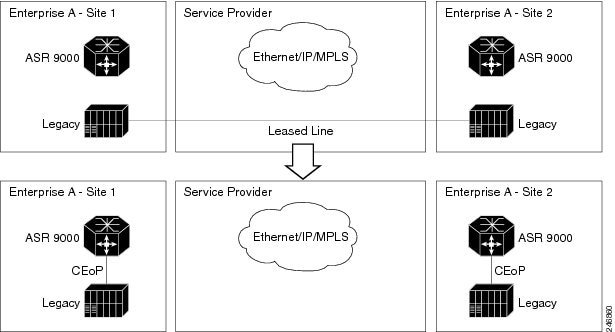
Circuit Emulation Over Packet Switched Network
Circuit Emulation over Packet (CEoP) is a method of carrying Time Division Multiplexed (TDM) circuits over packet switched network. CEoP is similar to a physical connection. The goal of CEoP is to replace leased lines and legacy TDM networks (Figure 12).
CEoP operates in two major modes:
•![]() Unstructured mode is called SAToP (Structure Agnostic TDM over Packet)
Unstructured mode is called SAToP (Structure Agnostic TDM over Packet)
SAToP addresses only structure-agnostic transport, i.e., unframed E1, T1, E3 and T3. It segments all TDM services as bit streams and then encapsulates them for transmission over a PW tunnel. This protocol can transparently transmit TDM traffic data and synchronous timing information. SAToP completely disregards any structure and provider edge routers (PEs) do not need to interpret the TDM data or to participate in the TDM signaling. The protocol is a simple way for transparent transmission of PDH bit-streams.
•![]() Structured mode is named CESoPSN (Circuit Emulation Service over Packet Switched Network)
Structured mode is named CESoPSN (Circuit Emulation Service over Packet Switched Network)
Compared with SAToP, CESoPSN transmits emulated structured TDM signals. That is, it can identify and process the frame structure and transmit signaling in TDM frames. It may not transmit idle timeslot channels, but only extracts useful timeslots of CE devices from the E1 traffic stream and then encapsulates them into PW packets for transmission.
CEoP SPAs are half-height (HH) Shared Port Adapters (SPA) and the CEoP SPA family consists of 24xT1/E1, 2xT3/E3, and 1xOC3/STM1 unstructured and structured (NxDS0) quarter rate, half height SPAs.
The CEM functionality is supported only on Cisco XR 12000 Series Router Engine 5 line cards having CEoP SPAs. CEM is supported on these variants of the CEoP SPAs:
•![]() 24-Port Channelized T1/E1 ATM CEoP SPA (SPA-24CHT1-CE-ATM)
24-Port Channelized T1/E1 ATM CEoP SPA (SPA-24CHT1-CE-ATM)
•![]() 2-Port Channelized T3/E3 ATM CEoP SPA (SPA-2CHT3-CE-ATM)
2-Port Channelized T3/E3 ATM CEoP SPA (SPA-2CHT3-CE-ATM)
•![]() 1-port Channelized OC3 STM1 ATM CEoP SPA (SPA-1CHOC3-CE-ATM)
1-port Channelized OC3 STM1 ATM CEoP SPA (SPA-1CHOC3-CE-ATM)
Figure 12 Enterprise Data Convergence using Circuit Emulation over Packet
CESoPSN and SAToP can use MPLS, UDP/IP, and L2TPv3 for the underlying transport mechanism. This release supports only MPLS transport mechanism.
Benefits of Circuit Emulation over Packet Switched Network
CEM offers these benefits to the service provider and end users:
•![]() Saving cost in installing equipment.
Saving cost in installing equipment.
•![]() Saving cost in network operations; as leased lines are expensive, limiting their usage to access only mode saves significant costs.
Saving cost in network operations; as leased lines are expensive, limiting their usage to access only mode saves significant costs.
•![]() Ensuring low maintenance cost because only the core network needs to be maintained.
Ensuring low maintenance cost because only the core network needs to be maintained.
•![]() Utilizing the core network resources more efficiently with packet switched network, while keeping investment in access network intact.
Utilizing the core network resources more efficiently with packet switched network, while keeping investment in access network intact.
•![]() Providing cheaper services to the end-user.
Providing cheaper services to the end-user.
L2VPN Nonstop Routing
The L2VPN Nonstop Routing (NSR) feature avoids label distribution path (LDP) sessions from flapping on events such as process failures (cras h) and route processor failover (RP FO). NSR on process failure (crash) is supported by performing RP FO, if you have enabled NSR using NSR process failure switchover.
NSR enables the router (where failure has occurred) to maintain the control plane states without a graceful restart (GR). NSR, by definition, does not require any protocol extension and typically uses Stateful Switch Over (SSO) to maintain it's control plane states.
Pseudowire Grouping
When pseudowires (PW) are established, each PW is assigned a group ID that is common for all PWs created from the same physical port. Hence, when the physical port becomes non-functional or is deleted, L2VPN sends a single message to advertise the status change of all PWs belonging to the group. A single L2VPN signal thus avoids a lot of processing and loss in reactivity.
Note ![]() Pseudowire grouping is disabled by default.
Pseudowire grouping is disabled by default.
How to Implement L2VPN
This section describes the tasks required to implement L2VPN:
•![]() Configuring an Interface or Connection for L2VPN
Configuring an Interface or Connection for L2VPN
•![]() Configuring Static Point-to-Point Cross-Connects
Configuring Static Point-to-Point Cross-Connects
•![]() Configuring Dynamic Point-to-Point Cross-Connects
Configuring Dynamic Point-to-Point Cross-Connects
•![]() Configuring L2VPN Quality of Service
Configuring L2VPN Quality of Service
•![]() Configuring Preferred Tunnel Path
Configuring Preferred Tunnel Path
•![]() Configuring AToM IP Interworking
Configuring AToM IP Interworking
•![]() Configuring Circuit Emulation Over Packet Switched Network
Configuring Circuit Emulation Over Packet Switched Network
•![]() Configuring L2VPN Nonstop Routing
Configuring L2VPN Nonstop Routing
Configuring an Interface or Connection for L2VPN
Perform this task to configure an interface or a connection for L2VPN.
SUMMARY STEPS
1. ![]() configure
configure
2. ![]() interface type interface-path-id
interface type interface-path-id
3. ![]() l2transport
l2transport
4. ![]() exit
exit
5. ![]() interface type interface-path-id
interface type interface-path-id
6. ![]() dot1q native vlan vlan-id
dot1q native vlan vlan-id
7. ![]() end
end
or
commit
DETAILED STEPS
Configuring Static Point-to-Point Cross-Connects
Perform this task to configure static point-to-point cross-connects.
Please consider this information about cross-connects when you configure static point-to-point cross-connects:
•![]() An cross-connect is uniquely identified with the pair; the cross-connect name must be unique within a group.
An cross-connect is uniquely identified with the pair; the cross-connect name must be unique within a group.
•![]() A segment (an attachment circuit or pseudowire) is unique and can belong only to a single cross-connect.
A segment (an attachment circuit or pseudowire) is unique and can belong only to a single cross-connect.
•![]() A static VC local label is globally unique and can be used in one pseudowire only.
A static VC local label is globally unique and can be used in one pseudowire only.
•![]() No more than 16,000 cross-connects can be configured per router.
No more than 16,000 cross-connects can be configured per router.
Note ![]() Static pseudowire connections do not use LDP for signaling.
Static pseudowire connections do not use LDP for signaling.
SUMMARY STEPS
1. ![]() configure
configure
2. ![]() l2vpn
l2vpn
3. ![]() xconnect group group-name
xconnect group group-name
4. ![]() p2p xconnect-name
p2p xconnect-name
5. ![]() interworking ethernet
interworking ethernet
6. ![]() interface type interface-path-id
interface type interface-path-id
7. ![]() neighbor ip-address pw-id pseudowire-id
neighbor ip-address pw-id pseudowire-id
8. ![]() mpls static label local {value} remote {value}
mpls static label local {value} remote {value}
9. ![]() end
end
or
commit
10. ![]() show l2vpn xconnect group group name
show l2vpn xconnect group group name
DETAILED STEPS
Configuring Dynamic Point-to-Point Cross-Connects
Perform this task to configure dynamic point-to-point cross-connects.
Note ![]() For dynamic cross-connects, LDP must be up and running. To support MPLS Transport based PWs, configure the IGP Routing Protocol.
For dynamic cross-connects, LDP must be up and running. To support MPLS Transport based PWs, configure the IGP Routing Protocol.
SUMMARY STEPS
1. ![]() configure
configure
2. ![]() l2vpn
l2vpn
3. ![]() xconnect group group-name
xconnect group group-name
4. ![]() p2p xconnect-name
p2p xconnect-name
5. ![]() interworking ipv4 or interworking ethernet
interworking ipv4 or interworking ethernet
6. ![]() interface type interface-path-id
interface type interface-path-id
7. ![]() neighbor ip-address pw-id pseudowire-id
neighbor ip-address pw-id pseudowire-id
8. ![]() end
end
or
commit
DETAILED STEPS
Configuring Inter-AS
The Inter-AS configuration procedure is identical to the L2VPN cross-connect configuration tasks (see "Configuring Static Point-to-Point Cross-Connects" section and "Configuring Dynamic Point-to-Point Cross-Connects" section) except that the remote PE IP address used by the cross-connect configuration is now reachable through iBGP peering.
Note ![]() You must be knowledgeable about IBGP, EBGP, and ASBR terminology and configurations to complete this configuration.
You must be knowledgeable about IBGP, EBGP, and ASBR terminology and configurations to complete this configuration.
Configuring L2VPN Quality of Service
This section describes how to configure L2VPN quality of service (QoS) in port mode, VLAN mode, Frame Relay and ATM sub-interfaces.
Restrictions
The l2transport command cannot be used with any IP address, L3, or CDP configuration.
Configuring an L2VPN Quality of Service Policy in Port Mode
This procedure describes how to configure an L2VPN QoS policy in port mode.
Note ![]() In port mode, the interface name format does not include a subinterface number; for example, GigabitEthernet0/1/0/1.
In port mode, the interface name format does not include a subinterface number; for example, GigabitEthernet0/1/0/1.
SUMMARY STEPS
1. ![]() configure
configure
2. ![]() interface type interface-path-id.subinterface l2transport
interface type interface-path-id.subinterface l2transport
3. ![]() service-policy [input | output] [policy-map-name]
service-policy [input | output] [policy-map-name]
4. ![]() end
end
or
commit
DETAILED STEPS
Configuring an L2VPN Quality of Service Policy in VLAN Mode
This procedure describes how to configure a L2VPN QoS policy in VLAN mode.
Note ![]() In VLAN mode, the interface name must include a subinterface; for example, GigabitEthernet0/1/0/1.1; and the l2transport command must follow the interface type on the same CLI line (for example, "interface GigabitEthernet0/0/0/0.1 l2transport").
In VLAN mode, the interface name must include a subinterface; for example, GigabitEthernet0/1/0/1.1; and the l2transport command must follow the interface type on the same CLI line (for example, "interface GigabitEthernet0/0/0/0.1 l2transport").
SUMMARY STEPS
1. ![]() configure
configure
2. ![]() interface type interface-path-id.subinterface l2transport
interface type interface-path-id.subinterface l2transport
3. ![]() service-policy [input | output] [policy-map-name]
service-policy [input | output] [policy-map-name]
4. ![]() end
end
or
commit
DETAILED STEPS
Configuring an L2VPN Quality of Service Policy in Frame Relay Mode
This procedure describes how to configure a L2VPN QoS policy in Frame Relay mode.
SUMMARY STEPS
1. ![]() configure
configure
2. ![]() class-map match-any [new class map name]
class-map match-any [new class map name]
3. ![]() match frame-relay dlci [dlci number]
match frame-relay dlci [dlci number]
4. ![]() end
end
or
commit
DETAILED STEPS
Configuring Preferred Tunnel Path
This procedure describes how to configure a preferred tunnel path.
SUMMARY STEPS
1. ![]() configure
configure
2. ![]() l2vpn
l2vpn
3. ![]() pw-class {name}
pw-class {name}
4. ![]() encapsulation mpls
encapsulation mpls
5. ![]() preferred-path {interface} {tunnel-ip value | tunnel-te value | tunnel-tp value} [fallback disable]
preferred-path {interface} {tunnel-ip value | tunnel-te value | tunnel-tp value} [fallback disable]
6. ![]() end
end
or
commit
DETAILED STEPS
Configuring AToM IP Interworking
To configure AToM IP interworking, you need to configure attachment circuits (AC), pseudowire class, and cross connects.
•![]() Configuring Ethernet ACs for AToM IP Interworking
Configuring Ethernet ACs for AToM IP Interworking
•![]() Configuring Frame Relay ACs for AToM IP Interworking
Configuring Frame Relay ACs for AToM IP Interworking
•![]() Configuring ATM AAL5 ACs for AToM IP Interworking
Configuring ATM AAL5 ACs for AToM IP Interworking
•![]() Configuring PPP ACs for AToM IP Interworking
Configuring PPP ACs for AToM IP Interworking
•![]() Configuring Local Switching on PPP ACs
Configuring Local Switching on PPP ACs
•![]() Configuring IP Interworking on PPP ACs
Configuring IP Interworking on PPP ACs
•![]() Configuring cHDLC ACs for AToM IP Interworking
Configuring cHDLC ACs for AToM IP Interworking
•![]() Configuring Local Switching on cHDLC ACs
Configuring Local Switching on cHDLC ACs
•![]() Configuring IP Interworking on cHDLC ACs
Configuring IP Interworking on cHDLC ACs
•![]() Configuring Frame Relay AC for Bridged Interworking
Configuring Frame Relay AC for Bridged Interworking
Configuring Ethernet ACs for AToM IP Interworking
Perform this task to configure an Ethernet AC for AToM IP Interworking.
SUMMARY STEPS
1. ![]() configure
configure
2. ![]() interface type interface-path-id
interface type interface-path-id
3. ![]() l2transport
l2transport
4. ![]() end
end
or
commit
DETAILED STEPS
Configuring Frame Relay ACs for AToM IP Interworking
Perform this task to configure a Frame Relay AC for AToM IP Interworking.
SUMMARY STEPS
1. ![]() configure
configure
2. ![]() interface type interface-path-id
interface type interface-path-id
3. ![]() encapsulation frame-relay frame-relay networks
encapsulation frame-relay frame-relay networks
4. ![]() frame-relay [intf-type] dce
frame-relay [intf-type] dce
5. ![]() interface type interface-path-id l2transport
interface type interface-path-id l2transport
6. ![]() pvc number
pvc number
7. ![]() end
end
or
commit
DETAILED STEPS
Configuring ATM AAL5 ACs for AToM IP Interworking
Perform this task to configure an ATM AAL5 AC for AToM IP Interworking.
SUMMARY STEPS
1. ![]() configure
configure
2. ![]() interface type interface-path-id l2transport
interface type interface-path-id l2transport
3. ![]() pvc number
pvc number
4. ![]() encapsulation {aal5mux} {ipv4}
encapsulation {aal5mux} {ipv4}
5. ![]() Repeat steps 1 through 3
Repeat steps 1 through 3
6. ![]() encapsulation {aal5snap}
encapsulation {aal5snap}
7. ![]() end
end
or
commit
DETAILED STEPS
Configuring PPP ACs for AToM IP Interworking
Perform this task to configure a PPP AC for AToM IP Interworking.
SUMMARY STEPS
1. ![]() configure
configure
2. ![]() interface type interface-path-id
interface type interface-path-id
3. ![]() encapsulation ppp
encapsulation ppp
4. ![]() ppp ipcp proxy-address ip_address
ppp ipcp proxy-address ip_address
5. ![]() l2transport
l2transport
6. ![]() end
end
or
commit
DETAILED STEPS
Configuring Local Switching on PPP ACs
Perform this task to configure local switching on PPP ACs.
SUMMARY STEPS
1. ![]() configure
configure
2. ![]() l2vpn
l2vpn
3. ![]() xconnect group group-name
xconnect group group-name
4. ![]() p2p xconnect-name
p2p xconnect-name
5. ![]() interface type interface-path-id
interface type interface-path-id
6. ![]() interworking ipv4
interworking ipv4
7. ![]() end
end
or
commit
DETAILED STEPS
Configuring IP Interworking on PPP ACs
Perform this task to configure IP Interworking on PPP ACs.
SUMMARY STEPS
1. ![]() configure
configure
2. ![]() l2vpn
l2vpn
3. ![]() xconnect group group-name
xconnect group group-name
4. ![]() p2p xconnect-name
p2p xconnect-name
5. ![]() interface type interface-path-id
interface type interface-path-id
6. ![]() neighbor ip-address pw-id pseudowire-id
neighbor ip-address pw-id pseudowire-id
7. ![]() interworking ipv4
interworking ipv4
8. ![]() end
end
or
commit
DETAILED STEPS
Configuring cHDLC ACs for AToM IP Interworking
Perform this task to configure a cHDLC AC for AToM IP Interworking.
SUMMARY STEPS
1. ![]() configure
configure
2. ![]() interface type interface-path-id
interface type interface-path-id
3. ![]() l2transport
l2transport
4. ![]() end
end
or
commit
DETAILED STEPS
Configuring Local Switching on cHDLC ACs
Perform this task to configure local switching on cHDLC ACs.
SUMMARY STEPS
1. ![]() configure
configure
2. ![]() l2vpn
l2vpn
3. ![]() xconnect group group-name
xconnect group group-name
4. ![]() p2p xconnect-name
p2p xconnect-name
5. ![]() interface type interface-path-id
interface type interface-path-id
6. ![]() interworking ipv4
interworking ipv4
7. ![]() end
end
or
commit
DETAILED STEPS
Configuring IP Interworking on cHDLC ACs
Perform this task to configure IP Interworking on cHDLC ACs.
SUMMARY STEPS
1. ![]() configure
configure
2. ![]() l2vpn
l2vpn
3. ![]() xconnect group group-name
xconnect group group-name
4. ![]() p2p xconnect-name
p2p xconnect-name
5. ![]() interface type interface-path-id
interface type interface-path-id
6. ![]() neighbor ip-address pw-id pseudowire-id
neighbor ip-address pw-id pseudowire-id
7. ![]() interworking ipv4
interworking ipv4
8. ![]() end
end
or
commit
DETAILED STEPS
Configuring Frame Relay AC for Bridged Interworking
Perform this task to configure a Frame Relay AC for Bridged Interworking.
SUMMARY STEPS
1. ![]() configure
configure
2. ![]() interface type interface-path-id
interface type interface-path-id
3. ![]() encapsulation frame-relay frame-relay networks
encapsulation frame-relay frame-relay networks
4. ![]() load-interval interval
load-interval interval
5. ![]() frame-relay intf-type
frame-relay intf-type
6. ![]() frame-relay lmi disable
frame-relay lmi disable
7. ![]() interface type instance-path-id l2transport
interface type instance-path-id l2transport
8. ![]() pvc number
pvc number
9. ![]() end
end
or
commit
DETAILED STEPS
Configuring Pseudowire Class
Perform this task to configure a pseudowire class.
SUMMARY STEPS
1. ![]() configure
configure
2. ![]() l2vpn
l2vpn
3. ![]() pw-class class-name
pw-class class-name
4. ![]() encapsulation mpls
encapsulation mpls
5. ![]() protocol ldp
protocol ldp
6. ![]() vccv
vccv
7. ![]() end
end
or
commit
DETAILED STEPS
Configuring Circuit Emulation Over Packet Switched Network
Perform these tasks to configure CEoP:
•![]() Adding CEM attachment circuit to a Pseudowire
Adding CEM attachment circuit to a Pseudowire
•![]() Associating a Pseudowire Class
Associating a Pseudowire Class
•![]() Configuring a Backup Pseudowire
Configuring a Backup Pseudowire
Adding CEM attachment circuit to a Pseudowire
Perform this task to add a CEM attachment circuit to a pseudowire.
SUMMARY STEPS
1. ![]() configure
configure
2. ![]() l2vpn
l2vpn
3. ![]() xconnect group group-name
xconnect group group-name
4. ![]() p2p xconnect-name
p2p xconnect-name
5. ![]() interface type interface-path-id
interface type interface-path-id
6. ![]() neighbor A.B.C.D ip-address pw-id pseudowire-id
neighbor A.B.C.D ip-address pw-id pseudowire-id
7. ![]() end
end
or
commit
DETAILED STEPS
Associating a Pseudowire Class
Perform this task to associate the attachment circuit with a pseudowire class.
SUMMARY STEPS
1. ![]() configure
configure
2. ![]() l2vpn
l2vpn
3. ![]() pw-class class-name
pw-class class-name
4. ![]() encapsulation mpls
encapsulation mpls
5. ![]() protocol ldp
protocol ldp
6. ![]() end
end
7. ![]() xconnect group group-name
xconnect group group-name
8. ![]() p2p xconnect-name
p2p xconnect-name
9. ![]() interface type interface-path-id
interface type interface-path-id
10. ![]() neighbor A.B.C.D ip-address pw-id pseudowire-id
neighbor A.B.C.D ip-address pw-id pseudowire-id
11. ![]() pw-class class-name
pw-class class-name
12. ![]() end
end
or
commit
DETAILED STEPS
Configuring a Backup Pseudowire
Perform this task to configure a backup pseudowire for a point-to-point neighbor.
SUMMARY STEPS
1. ![]() configure
configure
2. ![]() l2vpn
l2vpn
3. ![]() xconnect group group-name
xconnect group group-name
4. ![]() p2p {xconnect-name}
p2p {xconnect-name}
5. ![]() neighbor {A.B.C.D} {pw-id value}
neighbor {A.B.C.D} {pw-id value}
6. ![]() backup {neighbor A.B.C.D} {pw-id value}
backup {neighbor A.B.C.D} {pw-id value}
7. ![]() end
end
or
commit
DETAILED STEPS
Configuring L2VPN Nonstop Routing
Perform this task to configure L2VPN Nonstop Routing.
SUMMARY STEPS
1. ![]() configure
configure
2. ![]() l2vpn
l2vpn
3. ![]() nsr
nsr
4. ![]() logging nsr
logging nsr
5. ![]() end
end
or
commit
DETAILED STEPS
Enabling Pseudowire Grouping
Perform this task to enable pseudowire grouping.
SUMMARY STEPS
1. ![]() configure
configure
2. ![]() l2vpn
l2vpn
3. ![]() pw-grouping
pw-grouping
4. ![]() end
end
or
commit
DETAILED STEPS
Configuration Examples for L2VPN
In this example, two traffic classes are created and their match criteria are defined. For the first traffic class called class1, ACL 101 is used as the match criterion. For the second traffic class called class2, ACL 102 is used as the match criterion. Packets are checked against the contents of these ACLs to determine if they belong to the class.
This section includes these configuration examples:
•![]() L2VPN Interface Configuration: Example
L2VPN Interface Configuration: Example
•![]() Point-to-Point Cross-connect Configuration: Examples
Point-to-Point Cross-connect Configuration: Examples
•![]() L2VPN Quality of Service: Example
L2VPN Quality of Service: Example
•![]() AToM IP Interworking: Examples
AToM IP Interworking: Examples
•![]() AToM Cross Connect Configuration: Example
AToM Cross Connect Configuration: Example
•![]() Configuring L2VPN over GRE Tunnels: Example
Configuring L2VPN over GRE Tunnels: Example
•![]() Configuring Circuit Emulation Over Packet Switched Network: Example
Configuring Circuit Emulation Over Packet Switched Network: Example
•![]() Configuring L2VPN Nonstop Routing: Example
Configuring L2VPN Nonstop Routing: Example
•![]() Enabling Pseudowire Grouping: Example
Enabling Pseudowire Grouping: Example
L2VPN Interface Configuration: Example
The following example shows how to configure an L2VPN interface:
configure
interface GigabitEthernet0/0/0/0.1 l2transport
dot1q vlan 1
end
Point-to-Point Cross-connect Configuration: Examples
This section includes configuration examples for both static and dynamic point-to-point cross-connects.
Static Configuration
The following example shows how to configure a static point-to-point cross-connect:
configure
l2vpn
xconnect group vlan_grp_1
p2p vlan1
interworking ipv4
interface GigabitEthernet0/0/0/0.1
neighbor 2.2.2.2 pw-id 2000
mpls static label local 699 remote 890
commit
Dynamic Configuration
The following example shows how to configure a dynamic point-to-point cross-connect:
configure
l2vpn
xconnect group vlan_grp_1
p2p vlan1
interworking ipv4
interface GigabitEthernet0/0/0/0.1
neighbor 2.2.1.1 pw-id 1commit
The following example shows how to configure a dynamic point-to-point cross-connect using OSPF and MPLS LDP:
configure
l2vpn
pw-class ceop
encapsulation mpls
!
xconnect group SATOP
p2p STP1
interface CEM0/2/1/0/1/1/1/1
neighbor 24.24.24.2 pw-id 1001
pw-class ceop
!
xconnect group CESOPSN
p2p CSPN1
interface CEM0/2/1/0/1/1/1/2:0
neighbor 24.24.24.2 pw-id 1002
pw-class ceop
!
show runn router ospf
router ospf 10
router-id 21.21.21.1
area 0
interface Loopback0
!
interface GigabitEthernet0/2/2/0 <<< Core Facing Interface
!
!
!
RP/0/RSP0/CPU0:CEOP-03#
RP/0/RSP0/CPU0:CEOP-03#
RP/0/RSP0/CPU0:CEOP-03#show runn mpls ldp mpls ldp
 graceful-restart                 <<<< required to avoid drops during L2VPN_MGR process
restarts
interface GigabitEthernet0/2/2/0 <<< Core Facing Interface !
!
Inter-AS: Example
The following example shows how to set up an AC to AC cross-connect from AC1 to AC2:
router-id Loopback0
interface Loopback0
ipv4 address 127.0.0.1 255.255.255.0
!
interface GigabitEthernet0/1/0/0.1 l2transport dot1q vlan 1!
!
interface GigabitEthernet0/0/0/3
ipv4 address 127.0.0.1 255.255.255.0
keepalive disable
!
interface GigabitEthernet0/0/0/4
ipv4 address 127.0.0.1 255.255.255.0
keepalive disable
!
router ospf 100
log adjacency changes detail
area 0
interface Loopback0
!
interface GigabitEthernet0/0/0/3
!
interface GigabitEthernet0/0/0/4
!
!
!
router bgp 100
address-family ipv4 unicast
allocate-label all
!
neighbor 40.0.0.5
remote-as 100
update-source Loopback0
address-family ipv4 unicast
!
address-family ipv4 labeled-unicast
!
!
!
l2vpn
xconnect group xc1
p2p ac2ac1
interface GigabitEthernet0/1/0/0.1
neighbor 20.0.0.5 pw-id 101
!
p2p ac2ac2
interface GigabitEthernet0/1/0/0.2
neighbor 20.0.0.5 pw-id 102
!
p2p ac2ac3
interface GigabitEthernet0/1/0/0.3
neighbor 20.0.0.5 pw-id 103
!
p2p ac2ac4
interface GigabitEthernet0/1/0/0.4
neighbor 20.0.0.5 pw-id 104
!
p2p ac2ac5
interface GigabitEthernet0/1/0/0.5
neighbor 20.0.0.5 pw-id 105
!
p2p ac2ac6
interface GigabitEthernet0/1/0/0.6
neighbor 20.0.0.5 pw-id 106
!
p2p ac2ac7
interface GigabitEthernet0/1/0/0.7
neighbor 20.0.0.5 pw-id 107
!
p2p ac2ac8
interface GigabitEthernet0/1/0/0.8
neighbor 20.0.0.5 pw-id 108
!
p2p ac2ac9
interface GigabitEthernet0/1/0/0.9
neighbor 20.0.0.5 pw-id 109
!
p2p ac2ac10
interface GigabitEthernet0/1/0/0.10
neighbor 20.0.0.5 pw-id 110
!
!
!
mpls ldp
router-id Loopback0
log
neighbor
!
interface GigabitEthernet0/0/0/3
!
interface GigabitEthernet0/0/0/4
!
!
end
L2VPN Quality of Service: Example
The following example shows how to attach a service-policy to an L2 interface in port mode:
configure
interface GigabitEthernet 0/0/0/0
l2transport
service-policy [input | output] [policy-map-name]
commit
Preferred Path: Example
The following example shows how to configure preferred tunnel path:
configure
l2vpn
pw-class path1
encapsulation mpls
preferred-path interface tunnel-ip value fallback disable
AToM IP Interworking: Examples
This section includes configuration examples for all supported AC modes in AToM IP Interworking.
Ethernet
interface GigabitEthernet0/0/0/2
l2transport
!
interface GigabitEthernet0/0/0/3.1 l2transport
dot1q vlan 1
!
interface GigabitEthernet0/0/0/3.2 l2transport
dot1q vlan 2 2
Frame Relay
interface POS0/2/0/1
mtu 1500
encapsulation frame-relay
frame-relay intf-type dce
!
interface POS0/2/0/1.20 l2transport
pvc 20
!
ATM AAL5
interface ATM0/3/0/1.200 l2transport
pvc 20/200
encapsulation aal5mux ipv4
!
interface ATM0/3/0/1.300 l2transport
pvc 30/300
encapsulation aal5snap
!
interface ATM0/3/0/1.300 l2transport
pvc 30/400
encapsulation aal5nlpid
PPP
interface POS0/0/0/0
encapsulation ppp
ppp ipcp proxy-address 1.2.3.4
l2transport
!
!
interface POS0/0/0/1
ppp ipcp proxy-address 1.2.3.14
encapsulation ppp
l2transport
!
!
l2vpn
xconnect group foo
p2p bar
interface POS0/0/0/0
interface POS0/0/0/1
interworking ipv4
!
!
!
l2vpn
xconnect group foo
p2p bar
interface POS0/0/0/0
neighbor 10.1.1.1 pw-id 666
interworking ipv4
cHDLC
interface pos 0/1/0/1
l2transport
interface pos 0/1/0/2
l2transport
l2vpn
xconnect group foo
p2p bar
interface POS 0/1/0/1
interface POS 0/1/0/2
interworking ipv4
!
!
!
l2vpn
xconnect group foo
p2p bar
interface POS 0/1/0/1
neighbor 10.1.1.1 pw-id 666
interworking ipv4
!
!
Bridged Interworking: Example
interface POS0/2/0/1
mtu 1504
encapsulation frame-relay
load-interval 30
frame-relay intf-type dce
frame-relay lmi disable
!
interface POS0/2/0/1.20 l2transport
pvc 20
ATM AAL5 to Ethernet Bridged Interworking: Example
ATM side:
controller T3 0/4/3/1
mode atm
!
interface ATM0/4/3/1.1 l2transport
pvc 50/50
encapsulation aal5snap
!
mtu 1500
!
l2vpn
pw-class mpls_class
encapsulation mpls
protocol ldp
!
!
xconnect group pe1_to_pe2
p2p xc2
interface ATM0/4/3/1.1
neighbor 5.5.5.5 pw-id 2
pw-class mpls_class
!
interworking ethernet
!
!
Ethernet side:
l2vpn
pw-class mpls_class
encapsulation mpls
protocol ldp
!
!
interface GigabitEthernet0/0/0/0.1 l2transport dot1q vlan 1 end !
xconnect group pe1_to_pe2
p2p xc2
interface GigabitEthernet0/3/0/0.1
neighbor 2.2.2.2 pw-id 2
pw-class mpls_class
!
interworking ethernet
!
!
AToM Cross Connect Configuration: Example
This section includes configuration examples for all supported AToM Cross Connects.
l2vpn
pseudowire-class ipiw
encapsulation mpls
!
xconnect group port
p2p port1
interface GigabitEthernet0/0/0/2
neighbor 11.11.11.11 pw-id 300 pw-class ipiw
!
!
xconnect group vlan
p2p vlan1
interface GigabitEthernet0/0/0/3.1
neighbor 11.11.11.11 pw-id 400 pw-class ipiw
!
!
xconnect group frame-relay
p2p frame1
interface POS0/2/0/1.20
neighbor 11.11.11.11 pw-id 600 pw-class ipiw
!
!
xconnect group atm
p2p atm1
interface ATM0/3/0/1.200
neighbor 11.11.11.11 pw-id 700 pw-class ipiw
!
p2p atm2
interface ATM0/3/0/1.300
neighbor 11.11.11.11 pw-id 800 pw-class ipiw
Configuring L2VPN over GRE Tunnels: Example
The following example shows how to configure L2VPN over GRE tunnels:
interface tunnel-ip101
ipv4 address 150.10.1.204 255.255.255.0
ipv6 address 150:10:1::204/64
tunnel mode gre ipv4
tunnel source Loopback1
tunnel destination 100.1.1.202
router ospf 1
router-id 100.0.1.204
cost 1
router-id Loopback0
area 1
interface Loopback0
!
interface tunnel-ip101
mpls ldp
router-id 100.0.1.204
interface tunnel-ip101
l2vpn
xconnect group pe2
p2p 2001
interface GigabitEthernet0/2/0/0.2001
neighbor 100.0.1.202 pw-id 2001
Configuring Circuit Emulation Over Packet Switched Network: Example
This example shows you how to configure Circuit Emulation Over Packet Switched Network:
Adding CEM Attachment Circuit to PW
l2vpn
xconnect group gr1
p2p p1
interface CEM 0/0/0/0:10
neighbor 3.3.3.3 pw-id 11
!
!
Associating Pseudowire Class
l2vpn
pw-class class-cem
encapsulation mpls
protocol ldp
!
!
xconnect group gr1
p2p p1
interface CEM0/0/0/0:20
neighbor 1.2.3.4 pw-id 11
pw-class class-cem
!
Enabling Pseudowire Status
l2vpn
pw-status
commit
Disabling Pseudowire Status
l2vpn
pw-status disable
commit
Configuring Backup Pseudowire
l2vpn
pw-status
pw-class class-cem
encapsulation mpls
protocol ldp
!
!
xconnect group gr1
p2p p1
interface CEM0/0/0/0:20
neighbor 1.2.3.4 pw-id 11
pw-class class-cem
backup neighbor 9.9.9.9 pw-id 1221
pw-class class-cem
!
!
Configuring L2VPN Nonstop Routing: Example
This example shows how to configure L2VPN Nonstop Routing.
config
l2vpn
nsr
logging nsr
Enabling Pseudowire Grouping: Example
This example shows how to enable pseudowire grouping.
config
l2vpn
pw-grouping
Additional References
For additional information related to implementing MPLS Layer 2 VPN, refer to the following references:
Related Documents
Standards
|
|
|
|---|---|
Technical Assistance Center (TAC) home page, containing 30,000 pages of searchable technical content, including links to products, technologies, solutions, technical tips, and tools. Registered Cisco.com users can log in from this page to access even more content. |
— |
1 Not all supported standards are listed. |
MIBs
|
|
|
|---|---|
— |
To locate and download MIBs using Cisco IOS XR software, use the Cisco MIB Locator found at the following URL and choose a platform under the Cisco Access Products menu: http://cisco.com/public/sw-center/netmgmt/cmtk/mibs.shtml |
RFCs
Technical Assistance
 Feedback