- Prerequisites for Implementing IS-IS
- Restrictions for Implementing IS-IS
- Information About Implementing IS-IS
- IS-IS Functional Overview
- Key Features Supported in the Cisco IOS XR IS-IS Implementation
- IS-IS Configuration Grouping
- IS-IS Configuration Modes
- IS-IS Interfaces
- Multitopology Configuration
- IPv6 Routing and Configuring IPv6 Addressing
- Limit LSP Flooding
- Maximum LSP Lifetime and Refresh Interval
- Single-Topology IPv6 Support
- Multitopology IPv6 for IS-IS
- IS-IS Authentication
- Nonstop Forwarding
- Multi-Instance IS-IS
- Multiprotocol Label Switching Traffic Engineering
- Overload Bit on Router
- Overload Bit Configuration During Multitopology Operation
- IS-IS Overload Bit Avoidance
- Default Routes
- Attached Bit on an IS-IS Instance
- IS-IS Support for Route Tags
- Multicast-Intact Feature
- Multicast Topology Support Using IS-IS
- MPLS Label Distribution Protocol IGP Synchronization
- Label Distribution Protocol IGP Auto-configuration
- MPLS TE Forwarding Adjacency
- MPLS TE Interarea Tunnels
- IP Fast Reroute
- IS-IS Over GRE Interfaces
- Unequal Cost Multipath Load-balancing for IS-IS
- Enabling IS-IS and Configuring Level 1 or Level 2 Routing
- Configuring Single Topology for IS-IS
- Configuring Multitopology Routing
- Configuring Multitopology for IS-IS
- Controlling LSP Flooding for IS-IS
- Configuring Nonstop Forwarding for IS-IS
- Configuring Authentication for IS-IS
- Configuring Keychains for IS-IS
- Configuring MPLS Traffic Engineering for IS-IS
- Tuning Adjacencies for IS-IS
- Setting SPF Interval for a Single-Topology IPv4 and IPv6 Configuration
- Customizing Routes for IS-IS
- Configuring MPLS LDP IS-IS Synchronization
- Enabling Multicast-Intact
- Tagging IS-IS Interface Routes
- Setting the Priority for Adding Prefixes to the RIB
- Configuring IP/LDP Fast Reroute
- Configuring IS-IS Overload Bit Avoidance
- ISIS Link Group
Implementing
IS-IS
Integrated Intermediate System-to-Intermediate System (IS-IS), Internet Protocol Version 4 (IPv4), is a standards-based Interior Gateway Protocol (IGP). The Cisco software implements the IP routing capabilities described in International Organization for Standardization (ISO)/International Engineering Consortium (IEC) 10589 and RFC 1995, and adds the standard extensions for single topology and multitopology IS-IS for IP Version 6 (IPv6).
This module describes how to implement IS-IS (IPv4 and IPv6) on your Cisco IOS XR network.
 Note | Currently, only default VRF is supported. VPNv4, VPNv6 and VPN routing and forwarding (VRF) address families, L3VPN and Multicast will be supported in a future release. |
- Prerequisites for Implementing IS-IS
- Restrictions for Implementing IS-IS
- Information About Implementing IS-IS
- Configuration Examples for Implementing IS-IS
- Where to Go Next
- Additional References
Prerequisites for Implementing IS-IS
You must be in a user group associated with a task group that includes the proper task IDs. The command reference guides include the task IDs required for each command. If you suspect user group assignment is preventing you from using a command, contact your AAA administrator for assistance.
Restrictions for Implementing IS-IS
When multiple instances of IS-IS are being run, an interface can be associated with only one instance (process). Instances may not share an interface.
Information About Implementing IS-IS
To implement IS-IS you need to understand the following concepts:
- IS-IS Functional Overview
- Key Features Supported in the Cisco IOS XR IS-IS Implementation
- IS-IS Configuration Grouping
- IS-IS Configuration Modes
- IS-IS Interfaces
- Multitopology Configuration
- IPv6 Routing and Configuring IPv6 Addressing
- Limit LSP Flooding
- Maximum LSP Lifetime and Refresh Interval
- Single-Topology IPv6 Support
- Multitopology IPv6 for IS-IS
- IS-IS Authentication
- Nonstop Forwarding
- Multi-Instance IS-IS
- Multiprotocol Label Switching Traffic Engineering
- Overload Bit on Router
- Overload Bit Configuration During Multitopology Operation
- IS-IS Overload Bit Avoidance
- Default Routes
- Attached Bit on an IS-IS Instance
- IS-IS Support for Route Tags
- Multicast-Intact Feature
- Multicast Topology Support Using IS-IS
- MPLS Label Distribution Protocol IGP Synchronization
- Label Distribution Protocol IGP Auto-configuration
- MPLS TE Forwarding Adjacency
- MPLS TE Interarea Tunnels
- IP Fast Reroute
- IS-IS Over GRE Interfaces
- Unequal Cost Multipath Load-balancing for IS-IS
- Enabling IS-IS and Configuring Level 1 or Level 2 Routing
- Configuring Single Topology for IS-IS
- Configuring Multitopology Routing
- Configuring Multitopology for IS-IS
- Controlling LSP Flooding for IS-IS
- Configuring Nonstop Forwarding for IS-IS
- Configuring Authentication for IS-IS
- Configuring Keychains for IS-IS
- Configuring MPLS Traffic Engineering for IS-IS
- Tuning Adjacencies for IS-IS
- Setting SPF Interval for a Single-Topology IPv4 and IPv6 Configuration
- Customizing Routes for IS-IS
- Configuring MPLS LDP IS-IS Synchronization
- Enabling Multicast-Intact
- Tagging IS-IS Interface Routes
- Setting the Priority for Adding Prefixes to the RIB
- Configuring IP/LDP Fast Reroute
- Configuring IS-IS Overload Bit Avoidance
- ISIS Link Group
IS-IS Functional Overview
Small IS-IS networks are typically built as a single area that includes all routers in the network. As the network grows larger, it may be reorganized into a backbone area made up of the connected set of all Level 2 routers from all areas, which is in turn connected to local areas. Within a local area, routers know how to reach all system IDs. Between areas, routers know how to reach the backbone, and the backbone routers know how to reach other areas.
The IS-IS routing protocol supports the configuration of backbone Level 2 and Level 1 areas and the necessary support for moving routing information between the areas. Routers establish Level 1 adjacencies to perform routing within a local area (intra-area routing). Routers establish Level 2 adjacencies to perform routing between Level 1 areas (interarea routing).
Each IS-IS instance can support either a single Level 1 or Level 2 area, or one of each. By default, all IS-IS instances automatically support Level 1 and Level 2 routing. You can change the level of routing to be performed by a particular routing instance using the is-type command.
Restrictions
When multiple instances of IS-IS are being run, an interface can be associated with only one instance (process). Instances may not share an interface.
Key Features Supported in the Cisco IOS XR IS-IS Implementation
The Cisco IOS XR implementation of IS-IS conforms to the IS-IS Version 2 specifications detailed in RFC 1195 and the IPv6 IS-IS functionality based on the Internet Engineering Task Force (IETF) IS-IS Working Group draft-ietf-isis-ipv6.txt document.
The following list outlines key features supported in the Cisco IOS XR implementation:
-
Single topology IPv6
-
Multitopology
-
Nonstop forwarding (NSF), both Cisco proprietary and IETF
-
Three-way handshake
-
Mesh groups
-
Multiple IS-IS instances
-
Configuration of a broadcast medium connecting two networking devices as a point-to-point link
-
Fast-flooding with different threads handling flooding and shortest path first (SPF).
Note | For information on IS-IS support for Bidirectional Forwarding Detection (BFD), see Cisco IOS XR Interface and Hardware Component Configuration Guide for the Cisco XR 12000 Series Router and Cisco IOS XR Interface and Hardware Component Command Reference for the Cisco XR 12000 Series Router. |
IS-IS Configuration Grouping
Cisco IOS XR groups all of the IS-IS configuration in router IS-IS configuration mode, including the portion of the interface configurations associated with IS-IS. To display the IS-IS configuration in its entirety, use the show running router isis command. The command output displays the running configuration for all configured IS-IS instances, including the interface assignments and interface attributes.
IS-IS Configuration Modes
The following sections show how to enter each of the configuration modes. From a mode, you can enter the ? command to display the commands available in that mode.
- Router Configuration Mode
- Router Address Family Configuration Mode
- Interface Configuration Mode
- Interface Address Family Configuration Mode
Router Configuration Mode
The following example shows how to enter router configuration mode:
  RP/0/0/CPU0:router# configuration
  RP/0/0/CPU0:router(config)# router isis isp
  RP/0/0/CPU0:router(config-isis)#
Router Address Family Configuration Mode
The following example shows how to enter router address family configuration mode:
  RP/0/0/CPU0:router(config)# router isis isp
  RP/0/0/CPU0:router(config-isis)# address-family
ipv4 u
nicast
  RP/0/0/CPU0:router(config-isis-af)#
Interface Configuration Mode
The following example shows how to enter interface configuration mode:
  RP/0/0/CPU0:router(config)# router isis isp
  RP/0/0/CPU0:router(config-isis)# interface  GigabitEthernet 0
/3/0/0
  RP/0/0/CPU0:router(config-isis-if)#
Interface Address Family Configuration Mode
The following example shows how to enter interface address family configuration mode:
  RP/0/0/CPU0:router(config)# router isis isp
  RP/0/0/CPU0:router(config-isis)# interface
GigabitEthernet 0 /3/0/0
  RP/0/0/CPU0:router(config-isis-if)# address-family ipv4 unicast
  RP/0/0/CPU0:router(config-isis-if-af)#
IS-IS Interfaces
IS-IS interfaces can be configured as one of the following types:
-
Active—advertises connected prefixes and forms adjacencies. This is the default for interfaces.
-
Passive—advertises connected prefixes but does not form adjacencies. The passive command is used to configure interfaces as passive. Passive interfaces should be used sparingly for important prefixes such as loopback addresses that need to be injected into the IS-IS domain. If many connected prefixes need to be advertised then the redistribution of connected routes with the appropriate policy should be used instead.
-
Suppressed—does not advertise connected prefixes but forms adjacencies. The suppress command is used to configure interfaces as suppressed.
-
Shutdown—does not advertise connected prefixes and does not form adjacencies. The shutdown command is used to disable interfaces without removing the IS-IS configuration.
Multitopology Configuration
The software supports multitopology for IPv6 IS-IS unless single topology is explicitly configured in IPv6 address-family configuration mode.
Note | IS-IS supports IP routing and not Open Systems Interconnection (OSI) Connectionless Network Service (CLNS) routing. |
IPv6 Routing and Configuring IPv6 Addressing
By default, IPv6 routing is disabled in the software. To enable IPv6 routing, you must assign IPv6 addresses to individual interfaces in the router using the ipv6 enable or ipv6 address command. See the Network Stack IPv4 and IPv6 Commands on Cisco IOS XR Software module of Cisco IOS XR IP Addresses and Services Command Reference for the Cisco XR 12000 Series Router.
Limit LSP Flooding
Limiting link-state packets (LSP) may be desirable in certain “meshy” network topologies. An example of such a network might be a highly redundant one such as a fully meshed set of point-to-point links over a nonbroadcast multiaccess (NBMA) transport. In such networks, full LSP flooding can limit network scalability. One way to restrict the size of the flooding domain is to introduce hierarchy by using multiple Level 1 areas and a Level 2 area. However, two other techniques can be used instead of or with hierarchy: Block flooding on specific interfaces and configure mesh groups.
Both techniques operate by restricting the flooding of LSPs in some fashion. A direct consequence is that although scalability of the network is improved, the reliability of the network (in the face of failures) is reduced because a series of failures may prevent LSPs from being flooded throughout the network, even though links exist that would allow flooding if blocking or mesh groups had not restricted their use. In such a case, the link-state databases of different routers in the network may no longer be synchronized. Consequences such as persistent forwarding loops can ensue. For this reason, we recommend that blocking or mesh groups be used only if specifically required, and then only after careful network design.
Flood Blocking on Specific Interfaces
With this technique, certain interfaces are blocked from being used for flooding LSPs, but the remaining interfaces operate normally for flooding. This technique is simple to understand and configure, but may be more difficult to maintain and more error prone than mesh groups in the long run. The flooding topology that IS-IS uses is fine-tuned rather than restricted. Restricting the topology too much (blocking too many interfaces) makes the network unreliable in the face of failures. Restricting the topology too little (blocking too few interfaces) may fail to achieve the desired scalability.
To improve the robustness of the network in the event that all nonblocked interfaces drop, use the csnp-interval command in interface configuration mode to force periodic complete sequence number PDUs (CSNPs) packets to be used on blocked point-to-point links. The use of periodic CSNPs enables the network to become synchronized.
Mesh Group Configuration
Configuring mesh groups (a set of interfaces on a router) can help to limit flooding. All routers reachable over the interfaces in a particular mesh group are assumed to be densely connected with each router having at least one link to every other router. Many links can fail without isolating one or more routers from the network.
In normal flooding, a new LSP is received on an interface and is flooded out over all other interfaces on the router. With mesh groups, when a new LSP is received over an interface that is part of a mesh group, the new LSP is not flooded over the other interfaces that are part of that mesh group.
Maximum LSP Lifetime and Refresh Interval
By default, the router sends a periodic LSP refresh every 15 minutes. LSPs remain in a database for 20 minutes by default. If they are not refreshed by that time, they are deleted. You can change the LSP refresh interval or maximum LSP lifetime. The LSP interval should be less than the LSP lifetime or else LSPs time out before they are refreshed. In the absence of a configured refresh interval, the software adjusts the LSP refresh interval, if necessary, to prevent the LSPs from timing out.
Single-Topology IPv6 Support
Single-topology IPv6 support on Cisco IOS XR software software allows IS-IS for IPv6 to be configured on interfaces along with an IPv4 network protocol. All interfaces must be configured with the identical set of network protocols, and all routers in the IS-IS area (for Level 1 routing) or the domain (for Level 2 routing) must support the identical set of network layer protocols on all interfaces.
In single-topology mode, IPv6 topologies work with both narrow and wide metric styles in IPv4 unicast topology. During single-topology operation, one shortest path first (SPF) computation for each level is used to compute both IPv4 and IPv6 routes. Using a single SPF is possible because both IPv4 IS-IS and IPv6 IS-IS routing protocols share a common link topology.
Multitopology IPv6 for IS-IS
Multitopology IPv6 for IS-IS assumes that multitopology support is required as soon as it detects interfaces configured for both IPv6 and IPv4 within the IS-IS stanza.
Because multitopology is the default behavior in the software, you must explicitly configure IPv6 to use the same topology as IPv4 to enable single-topology IPv6. Configure the single-topology command in IPv6 router address family configuration submode of the IS-IS router stanza.
The following example shows multitopology IS-IS being configured in IPv6.
  router isis isp
   net 49.0000.0000.0001.00
   interface POS0/3/0/0
    address-family ipv6 unicast
    metric-style wide level 1
    exit
  !
  interface POS0/3/0/0
   ipv6 address 2001::1/64
IS-IS Authentication
Authentication is available to limit the establishment of adjacencies by using the hello-password command, and to limit the exchange of LSPs by using the lsp-password command.
IS-IS supports plain-text authentication, which does not provide security against unauthorized users. Plain-text authentication allows you to configure a password to prevent unauthorized networking devices from forming adjacencies with the router. The password is exchanged as plain text and is potentially visible to an agent able to view the IS-IS packets.
When an HMAC-MD5 password is configured, the password is never sent over the network and is instead used to calculate a cryptographic checksum to ensure the integrity of the exchanged data.
IS-IS stores a configured password using simple encryption. However, the plain-text form of the password is used in LSPs, sequence number protocols (SNPs), and hello packets, which would be visible to a process that can view IS-IS packets. The passwords can be entered in plain text (clear) or encrypted form.
To set the domain password, configure the lsp-password command for Level 2; to set the area password, configure the lsp-password command for Level 1.
The keychain feature allows IS-IS to reference configured keychains. IS-IS key chains enable hello and LSP keychain authentication. Keychains can be configured at the router level (in the case of the lsp-password command) and at the interface level (in the case of the hello-password command) within IS-IS. These commands reference the global keychain configuration and instruct the IS-IS protocol to obtain security parameters from the global set of configured keychains.
IS-IS is able to use the keychain to implement hitless key rollover for authentication. ey rollover specification is time based, and in the event of clock skew between the peers, the rollover process is impacted. The configurable tolerance specification allows for the accept window to be extended (before and after) by that margin. This accept window facilitates a hitless key rollover for applications (for example, routing and management protocols).
See Cisco IOS XR System Security Guide for the Cisco XR 12000 Series Router for information on keychain management.
Nonstop Forwarding
On Cisco IOS XR software, NSF minimizes the amount of time a network is unavailable to its users following a route processor (RP) failover. The main objective of NSF is to continue forwarding IP packets and perform a graceful restart following an RP failover.
When a router restarts, all routing peers of that device usually detect that the device went down and then came back up. This transition results in what is called a routing flap, which could spread across multiple routing domains. Routing flaps caused by routing restarts create routing instabilities, which are detrimental to the overall network performance. NSF helps to suppress routing flaps in NSF-aware devices, thus reducing network instability.
NSF allows for the forwarding of data packets to continue along known routes while the routing protocol information is being restored following an RP failover. When the NSF feature is configured, peer networking devices do not experience routing flaps. Data traffic is forwarded through intelligent line cards while the standby RP assumes control from the failed active RP during a failover. The ability of line cards to remain up through a failover and to be kept current with the Forwarding Information Base (FIB) on the active RP is key to NSF operation.
When the Cisco IOS XR router running IS-IS routing performs an RP failover, the router must perform two tasks to resynchronize its link-state database with its IS-IS neighbors. First, it must relearn the available IS-IS neighbors on the network without causing a reset of the neighbor relationship. Second, it must reacquire the contents of the link-state database for the network.
The IS-IS NSF feature offers two options when configuring NSF:
If neighbor routers on a network segment are NSF aware, meaning that neighbor routers are running a software version that supports the IETF Internet draft for router restartability, they assist an IETF NSF router that is restarting. With IETF NSF, neighbor routers provide adjacency and link-state information to help rebuild the routing information following a failover.
In Cisco IOS XR software, Cisco NSF checkpoints (stores persistently) all the state necessary to recover from a restart without requiring any special cooperation from neighboring routers. The state is recovered from the neighboring routers, but only using the standard features of the IS-IS routing protocol. This capability makes Cisco NSF suitable for use in networks in which other routers have not used the IETF standard implementation of NSF.
Note | If you configure IETF NSF on the Cisco IOS XR router and a neighbor router does not support IETF NSF, the affected adjacencies flap, but nonstop forwarding is maintained to all neighbors that do support IETF NSF. A restart reverts to a cold start if no neighbors support IETF NSF. |
Multi-Instance IS-IS
You can configure up to eight IS-IS instances. MPLS can run on multiple IS-IS processes as long as the processes run on different sets of interfaces. Each interface may be associated with only a single IS-IS instance. Cisco IOS XR software prevents the double-booking of an interface by two instances at configuration time—two instances of MPLS configuration causes an error.
Because the Routing Information Base (RIB) treats each of the IS-IS instances as equal routing clients, you must be careful when redistributing routes between IS-IS instances. The RIB does not know to prefer Level 1 routes over Level 2 routes. For this reason, if you are running Level 1 and Level 2 instances, you must enforce the preference by configuring different administrative distances for the two instances.
Multiprotocol Label Switching Traffic Engineering
The MPLS TE feature enables an MPLS backbone to replicate and expand the traffic engineering capabilities of Layer 2 ATM and Frame Relay networks. MPLS is an integration of Layer 2 and Layer 3 technologies.
For IS-IS, MPLS TE automatically establishes and maintains MPLS TE label-switched paths across the backbone by using Resource Reservation Protocol (RSVP). The route that a label-switched path uses is determined by the label-switched paths resource requirements and network resources, such as bandwidth. Available resources are flooded by using special IS-IS TLV extensions in the IS-IS. The label-switched paths are explicit routes and are referred to as traffic engineering (TE) tunnels.
Overload Bit on Router
The overload bit is a special bit of state information that is included in an LSP of the router. If the bit is set on the router, it notifies routers in the area that the router is not available for transit traffic. This capability is useful in four situations:
-
During a serious but nonfatal error, such as limited memory.
-
During the startup and restart of the process. The overload bit can be set until the routing protocol has converged. However, it is not employed during a normal NSF restart or failover because doing so causes a routing flap.
-
During a trial deployment of a new router. The overload bit can be set until deployment is verified, then cleared.
-
During the shutdown of a router. The overload bit can be set to remove the router from the topology before the router is removed from service.
Overload Bit Configuration During Multitopology Operation
Because the overload bit applies to forwarding for a single topology, it may be configured and cleared independently for IPv4 and IPv6 during multitopology operation. For this reason, the overload is set from the router address family configuration mode. If the IPv4 overload bit is set, all routers in the area do not use the router for IPv4 transit traffic. However, they can still use the router for IPv6 transit traffic.
IS-IS Overload Bit Avoidance
The IS-IS overload bit avoidance feature allows network administrators to prevent label switched paths (LSPs) from being disabled when a router in that path has its Intermediate System-to-Intermediate System (IS-IS) overload bit set.
When the IS-IS overload bit avoidance feature is activated, all nodes with the overload bit set, including head nodes, mid nodes, and tail nodes, are ignored, which means that they are still available for use with label switched paths (LSPs).
Note | The IS-IS overload bit avoidance feature does not change the default behavior on nodes that have their overload bit set if those nodes are not included in the path calculation (PCALC). |
The IS-IS overload bit avoidance feature is activated using the following command:
mpls traffic-eng path-selection ignore overload
The IS-IS overload bit avoidance feature is deactivated using the no form of this command:
no mpls traffic-eng path-selection ignore overload
When the IS-IS overload bit avoidance feature is deactivated, nodes with the overload bit set cannot be used as nodes of last resort.
Default Routes
You can force a default route into an IS-IS routing domain. Whenever you specifically configure redistribution of routes into an IS-IS routing domain, the Cisco IOS XR software does not, by default, redistribute the default route into the IS-IS routing domain. The default-information originate command generates a default route into IS-IS, which can be controlled by a route policy. You can use the route policy to identify the level into which the default route is to be announced, and you can specify other filtering options configurable under a route policy. You can use a route policy to conditionally advertise the default route, depending on the existence of another route in the routing table of the router.
Attached Bit on an IS-IS Instance
The attached bit is set in a router that is configured with the is-type command and level-1-2 keyword. The attached bit indicates that the router is connected to other areas (typically through the backbone). This functionality means that the router can be used by Level 1 routers in the area as the default route to the backbone. The attached bit is usually set automatically as the router discovers other areas while computing its Level 2 SPF route. The bit is automatically cleared when the router becomes detached from the backbone.
Note | If the connectivity for the Level 2 instance is lost, the attached bit in the Level 1 instance LSP would continue sending traffic to the Level 2 instance and cause the traffic to be dropped. |
To simulate this behavior when using multiple processes to represent the level-1-2 keyword functionality, you would manually configure the attached bit on the Level 1 process.
IS-IS Support for Route Tags
The IS-IS Support for route tags feature provides the capability to associate and advertise a tag with an IS-IS route prefix. Additionally, the feature allows you to prioritize the order of installation of route prefixes in the RIB based on a tag of a route. Route tags may also be used in route policy to match route prefixes (for example, to select certain route prefixes for redistribution).
Multicast-Intact Feature
The multicast-intact feature provides the ability to run multicast routing (PIM) when IGP shortcuts are configured and active on the router. Both OSPFv2 and IS-IS support the multicast-intact feature. MPLS TE and IP multicast coexistence is supported in Cisco IOS XR software by using the mpls traffic-eng multicast-intact IS-IS or OSPF router command.
You can enable multicast-intact in the IGP when multicast routing protocols (PIM) are configured and IGP shortcuts are configured on the router. IGP shortcuts are MPLS tunnels that are exposed to IGP. The IGPs route the IP traffic over these tunnels to destinations that are downstream from the egress router of the tunnel (from an SPF perspective). PIM cannot use IGP shortcuts for propagating PIM joins because reverse path forwarding (RPF) cannot work across a unidirectional tunnel.
When you enable multicast-intact on an IGP, the IGP publishes a parallel or alternate set of equal-cost next-hops for use by PIM. These next-hops are called mcast-intact next-hops. The mcast-intact next-hops have the following attributes:
-
They are guaranteed not to contain any IGP shortcuts.
-
They are not used for unicast routing but are used only by PIM to look up an IPv4 next-hop to a PIM source.
-
They are not published to the FIB.
-
When multicast-intact is enabled on an IGP, all IPv4 destinations that were learned through link-state advertisements are published with a set equal-cost mcast-intact next-hops to the RIB. This attribute applies even when the native next-hops have no IGP shortcuts.
-
In IS-IS, the max-paths limit is applied by counting both the native and mcast-intact next-hops together. (In OSPFv2, the behavior is slightly different.)
Multicast Topology Support Using IS-IS
Multicast topology support allows for the configuration of IS-IS multicast topologies for IPv4 or IPv6 routing. IS-IS maintains a separate topology for multicast and runs a separate Shortest Path First (SPF) over the multicast topology. IS-IS multicast inserts routes from the IS-IS multicast topology into the multicast-unicast Routing Information Base (muRIB) table in the RIB for the corresponding address family. Since PIM uses the muRIB, PIM uses routes from the multicast topology instead of routes from the unicast topology.
MPLS Label Distribution Protocol IGP Synchronization
Multiprotocol Label Switching (MPLS) Label Distribution Protocol (LDP) Interior Gateway Protocol (IGP) Synchronization ensures that LDP has completed label exchange before the IGP path is used for switching. MPLS traffic loss can occur in the following two situations:
-
When an IGP adjacency is established, the router begins forwarding packets using the new adjacency before LDP has exchanged labels with peers on that link.
-
When an LDP session closes, the router continues to forward traffic using the link associated with the LDP peer rather than using an alternate path with an established LDP session.
This feature provides a mechanism to synchronize LDP and IS-IS to minimize MPLS packet loss. The synchronization is accomplished by changing the link metric for a neighbor IS-IS link-state packet (LSP), based on the state of the LDP session.
When an IS-IS adjacency is established on a link but the LDP session is lost or LDP has not yet completed exchanging labels, IS-IS advertises the maximum metric on that link. In this instance, LDP IS-IS synchronization is not yet achieved.
Note | In IS-IS, a link with a maximum wide metric (0xFFFFFF) is not considered for shortest path first (SPF). Therefore, the maximum wide metric of -1 (0XFFFFFE) is used with MPLS LDP IGP synchronization. |
When LDP IS-IS synchronization is achieved, IS-IS advertises a regular (configured or default) metric on that link.
- MPLS LDP-IGP Synchronization Compatibility with LDP Graceful Restart
- MPLS LDP-IGP Synchronization Compatibility with IGP Nonstop Forwarding
MPLS LDP-IGP Synchronization Compatibility with LDP Graceful Restart
LDP graceful restart protects traffic when an LDP session is lost. If a graceful restart-enabled LDP session fails, MPLS LDP IS-IS synchronization is still achieved on the interface while it is protected by graceful restart. MPLS LDP IGP synchronization is eventually lost under the following circumstances:
MPLS LDP-IGP Synchronization Compatibility with IGP Nonstop Forwarding
IS-IS nonstop forwarding (NSF) protects traffic during IS-IS process restarts and route processor (RP) failovers. LDP IS-IS synchronization is supported with IS-IS NSF only if LDP graceful restart is also enabled over the interface. If IS-IS NSF is not enabled, the LDP synchronization state is not retained across restarts and failovers.
Label Distribution Protocol IGP Auto-configuration
Label Distribution Protocol (LDP) Interior Gateway Protocol (IGP) auto-configuration simplifies the procedure to enable LDP on a set of interfaces used by an IGP instance. LDP IGP auto-configuration can be used on a large number interfaces (for example, when LDP is used for transport in the core) and on multiple IGP instances simultaneously.
This feature supports the IPv4 address family for the default VPN routing and forwarding (VRF) instance.
LDP IGP auto-configuration can also be explicitly disabled on individual interfaces under LDP using the igp auto-config disable command. This allows LDP to receive all IGP interfaces except the ones explicitly disabled.
See the MPLS configuration guide for information on configuring LDP IGP auto-configuration.
MPLS TE Forwarding Adjacency
MPLS TE forwarding adjacency allows a network administrator to handle a traffic engineering, label switch path (LSP) tunnel as a link in an Interior Gateway Protocol (IGP) network, based on the Shortest Path First (SPF) algorithm. A forwarding adjacency can be created between routers in the same IS-IS level. The routers can be located multiple hops from each other. As a result, a TE tunnel is advertised as a link in an IGP network, with the cost of the link associated with it. Routers outside of the TE domain see the TE tunnel and use it to compute the shortest path for routing traffic throughout the network.
MPLS TE forwarding adjacency is considered in IS-IS SPF only if a two-way connectivity check is achieved. This is possible if the forwarding adjacency is bidirectional or the head end and tail end routers of the MPLS TE tunnel are adjacent.
The MPLS TE forwarding adjacency feature is supported by IS-IS. For details on configuring MPLS TE forwarding adjacency, see the MPLS Configuration Guide.
MPLS TE Interarea Tunnels
MPLS TE interarea tunnels allow you to establish MPLS TE tunnels that span multiple IGP areas (Open Shorted Path First [OSPF]) and levels (IS-IS), removing the restriction that required that both the tunnel headend and tailend routers be in the same area. The IGP can be either IS-IS or OSPF. See the Configuring MPLS Traffic Engineering for IS-IS for information on configuring MPLS TE for IS-IS.
For details on configuring MPLS TE interarea tunnels, see the MPLS Configuration Guide.
IP Fast Reroute
The IP Fast Reroute (IPFRR) loop-free alternate (LFA) computation provides protection against link failure. Locally computed repair paths are used to prevent packet loss caused by loops that occur during network reconvergence after a failure. See IETF draft-ietf-rtgwg-ipfrr-framework-06.txt and draft-ietf-rtgwg-lf-conv-frmwk-00.txt for detailed information on IPFRR LFA.
IPFRR LFA is different from Multiprotocol Label Switching (MPLS) as it is applicable to networks using conventional IP routing and forwarding. See Cisco IOS XR MPLS Configuration Guide for the Cisco XR 12000 Series Router for information on configuring MPLS IPFRR.
IS-IS Over GRE Interfaces
Cisco IOS XR software provides the capability to run IS-IS protocols over Generic Routing Encapsulation (GRE) tunnel interfaces.
For more information on GRE tunnel interfaces, see Implementing BGP on Cisco IOS XR software module.
Unequal Cost Multipath Load-balancing for IS-IS
The unequal cost multipath (UCMP) load-balancing adds the capability with intermediate system-to-intermediate system (IS-IS) to load-balance traffic proportionally across multiple paths, with different cost.
Generally, higher bandwidth paths have lower IGP metrics configured, so that they form the shortest IGP paths. With the UCMP load-balancing enabled, IGP can use even lower bandwidth paths or higher cost paths for traffic, and can install these paths to the forwarding information base (FIB). IS-IS IGP still installs multiple paths to the same destination in FIB, but each path will have a 'load metric/weight' associated with it. FIB uses this load metric/weight to decide the amount of traffic that needs to be sent on a higher bandwidth path and the amount of traffic that needs to be sent on a lower bandwidth path.
The UCMP computation is provided under IS-IS per address family, enabling UCMP computation for a particular address family. The UCMP configuration is also provided with a prefix-list option, which would limit the UCMP computation only for the prefixes present in the prefix-list. If prefix-list option is not provided, UCMP computation is done for the reachable prefixes in IS-IS. The number of UCMP nexthops to be considered and installed is controlled using the variance configuration. Variance value identifies the range for the UCMP path metric to be considered for installation into routing information base (RIB) and is defined in terms of a percentage of the primary path metric. Total number of paths, including ECMP and UCMP paths together is limited by the max-path configuration or by the max-path capability of the platform.
Enabling the UCMP configuration indicates that IS-IS should perform UCMP computation for the all the reachable ISIS prefixes or all the prefixes in the prefix-list, if the prefix-list option is used. The UCMP computation happens only after the primary SPF and route calculation is completed. There would be a delay of ISIS_UCMP_INITIAL_DELAY (default delay is 100 ms) milliseconds from the time route calculation is completed and UCMP computation is started. UCMP computation will be done before fast re-route computation. Fast re-route backup paths will be calculated for both the primary equal cost multipath ( ECMP) paths and the UCMP paths. Use the ucmp delay-interval command to configure the delay between primary SPF completion and start of UCMP computation.
To manually change each path's bandwidth to adjust UCMP ratio, use the bandwidthcommand in interface configuration mode.
There is an option to exclude an interface from being used for UCMP computation. If it is desired that a particular interface should not be considered as a UCMP nexthop, for any prefix, then use the ucmp exclude interface command to configure the interface to be excluded from UCMP computation.
Enabling IS-IS and Configuring Level 1 or Level 2 Routing
This task explains how to enable IS-IS and configure the routing level for an area.
Note | Configuring the routing level in Step 4 is optional, but is highly recommended to establish the proper level of adjacencies. |
Although you can configure IS-IS before you configure an IP address, no IS-IS routing occurs until at least one IP address is configured.
1.
configure
2.
router isis
instance-id
3.
net
network-entity-title
4.
is-type
{
level-1
|
level-1-2
|
level-2-only
}
5.
commit
6.
show isis
[
instance
instance-id
]
protocol
DETAILED STEPS
Configuring Single Topology for IS-IS
After an IS-IS instance is enabled, it must be configured to compute routes for a specific network topology.
This task explains how to configure the operation of the IS-IS protocol on an interface for an IPv4 or IPv6 topology.
1.
configure
2.
interface
type
interface-path-id
3.
Do one of the
following:
4.
exit
5.
router
isis
instance-id
6.
net
network-entity-title
7.
address-family
ipv6
[
unicast
]
8.
single-topology
9.
exit
10.
interface
type
interface-path-id
11.
circuit-type
{
level-1
|
level-1-2
|
level-2-only
}
12.
address-family
{
ipv4
|
ipv6
} [
unicast
|
multicast
]
13.
commit
14.
show
isis
[
instance
instance-id
]
interface
[
type
interface-path-id
] [
detail
] [
level
{
1
|
2
}]
15.
show isis
[
instance
instance-id
]
topology
[
systemid
system-id
] [
level
{
1
|
2
}]
[
summary
]
DETAILED STEPS
| Command or Action | Purpose | |
|---|---|---|
| Step 1 |
configure
| |
| Step 2 |
interface
type
interface-path-id
Example:
RP/0/0/CPU0:router(config)# interface GigabitEthernet 0/1/0/3
|
Enters interface configuration mode. |
| Step 3 | Do one of the
following:
Example:
RP/0/0/CPU0:router(config-if)# ipv4 address 10.0.1.3 255.255.255.0
or RP/0/0/CPU0:router(config-if)# ipv6 address 3ffe:1234:c18:1::/64 eui-64 RP/0/0/CPU0:router(config-if)# ipv6 address FE80::260:3EFF:FE11:6770 link-local RP/0/0/CPU0:router(config-if)# ipv6 enableor |
Defines the IPv4 address for the interface. An IP address is required on all interfaces in an area enabled for IS-IS if any one interface is configured for IS-IS routing. or Specifies an IPv6 network assigned to the interface and enables IPv6 processing on the interface with the eui-64 keyword. or Specifies an IPv6 address assigned to the interface and enables IPv6 processing on the interface with the link-local keyword. or Automatically configures an IPv6 link-local address on the interface while also enabling the interface for IPv6 processing.
|
| Step 4 |
exit
Example:
RP/0/0/CPU0:router(config-if)# exit
|
Exits interface configuration mode, and returns the router to global configuration mode. |
| Step 5 |
router
isis
instance-id
Example:
RP/0/0/CPU0:router(config)# router isis isp
|
Enables IS-IS routing for the specified routing instance, and places the router in router configuration mode. |
| Step 6 |
net
network-entity-title
Example:
RP/0/0/CPU0:router(config-isis)# net 47.0004.004d.0001.0001.0c11.1110.00
|
Configures NETs for the routing instance.
|
| Step 7 |
address-family
ipv6
[
unicast
]
Example:
RP/0/0/CPU0:router(config-isis)# address-family ipv6 unicast
|
Specifies the IPv6 address family and enters router address family configuration mode. |
| Step 8 |
single-topology
Example:
RP/0/0/CPU0:router(config-isis-af)# single-topology
|
(Optional) Configures the link topology for IPv4 when IPv6 is configured.
|
| Step 9 |
exit
Example:
RP/0/0/CPU0:router(config-isis-af)# exit
|
Exits router address family configuration mode, and returns the router to router configuration mode. |
| Step 10 |
interface
type
interface-path-id
Example:
RP/0/0/CPU0:router(config-isis)# interface GigabitEthernet 0/1/0/3
|
Enters interface configuration mode. |
| Step 11 |
circuit-type
{
level-1
|
level-1-2
|
level-2-only
}
Example:
RP/0/0/CPU0:router(config-isis-if)# circuit-type level-1-2
|
(Optional) Configures the type of adjacency. |
| Step 12 |
address-family
{
ipv4
|
ipv6
} [
unicast
|
multicast
]
Example:
RP/0/0/CPU0:router(config-isis-if)# address-family ipv4 unicast
|
Specifies the IPv4 or IPv6 address family, and enters interface address family configuration mode. |
| Step 13 |
commit
| |
| Step 14 |
show
isis
[
instance
instance-id
]
interface
[
type
interface-path-id
] [
detail
] [
level
{
1
|
2
}]
Example:
RP/0/0/CPU0:router# show isis interface GigabitEthernet 0/1/0/1
|
(Optional) Displays information about the IS-IS interface. |
| Step 15 |
show isis
[
instance
instance-id
]
topology
[
systemid
system-id
] [
level
{
1
|
2
}]
[
summary
]
Example:
RP/0/0/CPU0:router# show isis topology
|
(Optional) Displays a list of connected routers in all areas. |
Configuring Multitopology Routing
This set of procedures configures multitopology routing, which is used by PIM for reverse-path forwarding (RPF) path selection.
- Restrictions for Configuring Multitopology Routing
- Information About Multitopology Routing
- Configuring a Global Topology and Associating It with an Interface
- Enabling an IS-IS Topology
- Placing an Interface in a Topology in IS-IS
- Configuring a Routing Policy
Restrictions for Configuring Multitopology Routing
-
Only the default VRF is currently supported in a multitopology solution.
-
Only protocol-independent multicast (PIM) and intermediate system-intermediate system (IS-IS) routing protocols are currently supported.
-
Topology selection is restricted solely to (S, G) route sources for both SM and SSM. Static and IS-IS are the only interior gateway protocols (IGPs) that support multitopology deployment.
For non-(S, G) route sources like a rendezvous point or bootstrap router (BSR), or when a route policy is not configured, the current policy default remains in effect. In other words, either a unicast-default or multicast-default table is selected for all sources, based on OSFP/IS-IS/Multiprotocol Border Gateway Protocol (MBGP) configuration.
Note | Although both multicast and unicast keywords are available when using the address-family {ipv4 | ipv6} command in routing policy language (RPL), only topologies under multicast SAFI can be configured globally. |
Information About Multitopology Routing
Configuring multitopology networks requires the following tasks:
Configuring a Global Topology and Associating It with an Interface
Follow these steps to enable a global topology in the default VRF and to enable its use with a specific interface.
1.
configure
2.
address-family
{
ipv4
|
ipv6
}
multicast
topology
topo-name
3.
maximum
prefix
limit
4.
interface
type
interface-path-id
5.
address-family
{
ipv4
|
ipv6
}
multicast
topology
topo-name
6. Repeat Step 4 and Step 5 until you have specified all the interface instances you want to associate with your topologies.
7.
commit
DETAILED STEPS
| Command or Action | Purpose | |
|---|---|---|
| Step 1 |
configure
| |
| Step 2 |
address-family
{
ipv4
|
ipv6
}
multicast
topology
topo-name
Example:
RP/0/0/CPU0:router(config)# address-family ipv4 multicast topology green
|
Configures a topology in the default VRF table that will be associated with a an interface. |
| Step 3 |
maximum
prefix
limit
Example:
RP/0/0/CPU0:router(config-af)# maximum prefix 100
|
(Optional) Limits the number of prefixes allowed in a topology routing table. Range is 32 to 2000000. |
| Step 4 |
interface
type
interface-path-id
Example:
RP/0/0/CPU0:router(config-af)# interface GigabitEthernet 0/3/0/0
|
Specifies the interface to be associated with the previously specified VRF table that will add the connected and local routes to the appropriate routing table. |
| Step 5 |
address-family
{
ipv4
|
ipv6
}
multicast
topology
topo-name
Example:
RP/0/0/CPU0:router(config-if)# address-family ipv4 multicast topology green
|
Enables the topology for the interface specified in Step 4, adding the connected and local routes to the appropriate routing table. |
| Step 6 | Repeat Step 4
and Step 5 until you have specified all the interface instances you want to
associate with your topologies.
Example: RP/0/0/CPU0:router(config-if-af)# interface gigabitethernet 0/3/2/0 RP/0/0/CPU0:routerrouter(config-if)# address-family ipv4 multicast topology purple RP/0/0/CPU0:router(config-if-af)# | — |
| Step 7 |
commit
|
Enabling an IS-IS Topology
To enable a topology in IS-IS, you must associate an IS-IS topology ID with the named topology. IS-IS uses the topology ID to differentiate topologies in the domain.
Note | This command must be configured prior to other topology commands. |
1.
configure
2.
router isis
instance-id
3.
address-family
{
ipv4
|
ipv6
}
multicast
topology
topo-name
4.
topology-id
multitoplogy-id
5.
commit
DETAILED STEPS
Placing an Interface in a Topology in IS-IS
To associate an interface with a topology in IS-IS, follow these steps.
1.
configure
2.
router isis
instance-id
3.
net
network-entity-title
4.
interface
type
interface-path-id
5.
address-family
{
ipv4
|
ipv6
}
multicast
topology
topo-name
6. Repeat Step 4 and Step 5 until you have specified all the interface instances and associated topologies you want to configure in your network.
7.
commit
DETAILED STEPS
| Command or Action | Purpose | |
|---|---|---|
| Step 1 |
configure
| |
| Step 2 |
router isis
instance-id
Example:
RP/0/0/CPU0:router(config)# router isis purple
|
Enters IS-IS configuration submode. |
| Step 3 |
net
network-entity-title
Example:
RP/0/0/CPU0:router(config-isis)# net netname
|
Creates a network entity title for the configured isis interface. |
| Step 4 |
interface
type
interface-path-id
Example:
RP/0/0/CPU0:router(config-isis)# interface gigabitethernet 0/3/0/0
|
Enters isis interface configuration submode and creates an interface instance. |
| Step 5 |
address-family
{
ipv4
|
ipv6
}
multicast
topology
topo-name
Example:
RP/0/0/CPU0:router(config-isis-if)# address-family ipv4 multicast topology green
| |
| Step 6 | Repeat Step 4 and Step 5 until you have specified all the interface instances and associated topologies you want to configure in your network. | — |
| Step 7 |
commit
|
Configuring a Routing Policy
For more information about creating a routing policy and about the set rpf-topology command, see Cisco IOS XR Routing Command Reference for the Cisco XR 12000 Series Router.
1.
configure
2.
route-policy
policy-name
3.
end-policy
4.
commit
DETAILED STEPS
Configuring Multitopology for IS-IS
Multitopology is configured in the same way as the single topology. However, the single - topology command is omitted, invoking the default multitopology behavior. This task is optional.
Controlling LSP Flooding for IS-IS
Flooding of LSPs can limit network scalability. You can control LSP flooding by tuning your LSP database parameters on the router globally or on the interface. This task is optional.
Many of the commands to control LSP flooding contain an option to specify the level to which they apply. Without the option, the command applies to both levels. If an option is configured for one level, the other level continues to use the default value. To configure options for both levels, use the command twice. For example:
  RP/0/0/CPU0:router(config-isis)# lsp-refresh-interval 1200 level 2
  RP/0/0/CPU0:router(config-isis)# lsp-refresh-interval 1100 level 1
1.
configure
2.
router isis
instance-id
3.
lsp-refresh-interval
seconds
[
level
{
1
|
2
}]
4.
lsp-check-interval
seconds
[
level
{
1
|
2
}]
5.
lsp-gen-interval
{
[
initial-wait
initial
|
secondary-wait
secondary
|
maximum-wait
maximum
]
...
}
[
level
{
1
|
2
}]
6.
lsp-mtu
bytes
[
level
{
1
|
2
}]
7.
max-lsp-lifetime
seconds
[
level
{
1
|
2
}]
8.
ignore-lsp-errors
disable
9.
interface
type
interface-path-id
10.
lsp-interval
milliseconds
[
level
{
1
|
2
}]
11.
csnp-interval
seconds
[
level
{
1
|
2
}]
12.
retransmit-interval
seconds
[
level
{
1
|
2
}]
13.
retransmit-throttle-interval
milliseconds
[
level
{
1
|
2
}]
14.
mesh-group
{
number
|
blocked
}
15.
commit
16.
show
isis
interface
[
type
interface-path-id
|
level
{
1
|
2
}] [
brief
]
17.
show
isis
[
instance
instance-id
]
database
[
level
{
1
|
2
}] [
detail
|
summary
|
verbose
] [
*
|
lsp-id
]
18.
show
isis
[
instance
instance-id
]
lsp-log
[
level
{
1
|
2
}]
19.
show isis
database-log
[
level
{
1
|
2
}]
DETAILED STEPS
Configuring Nonstop Forwarding for IS-IS
This task explains how to configure your router with NSF that allows the Cisco IOS XR software to resynchronize the IS-IS link-state database with its IS-IS neighbors after a process restart. The process restart could be due to an:
-
RP failover (for a warm restart)
-
Simple process restart (due to an IS-IS reload or other administrative request to restart the process)
-
IS-IS software upgrade
In all cases, NSF mitigates link flaps and loss of user sessions. This task is optional.
1.
configure
2.
router
isis
instance-id
3.
nsf
{
cisco
|
ietf
}
4.
nsf
interface-expires
number
5.
nsf
interface-timer
seconds
6.
nsf
lifetime
seconds
7.
commit
8.
show
running-config
[
command
]
DETAILED STEPS
Configuring Authentication for IS-IS
This task explains how to configure authentication for IS-IS. This task is optional.
1.
configure
2.
router
isis
instance-id
3.
lsp-password
{
hmac-md5
|
text
} {
clear
|
encrypted
}
password
[
level
{
1
|
2
}] [
send-only
] [
snp
send-only
]
4.
interface
type
interface-path-id
5.
hello-password
{
hmac-md5
|
text
} {
clear
|
encrypted
}
password
[
level
{
1
|
2
}] [
send-only
]
6.
commit
DETAILED STEPS
Configuring Keychains for IS-IS
This task explains how to configure keychains for IS-IS. This task is optional.
Keychains can be configured at the router level ( lsp-password command) and at the interface level ( hello-password command) within IS-IS. These commands reference the global keychain configuration and instruct the IS-IS protocol to obtain security parameters from the global set of configured keychains. The router-level configuration (lsp-password command) sets the keychain to be used for all IS-IS LSPs generated by this router, as well as for all Sequence Number Protocol Data Units (SN PDUs). The keychain used for HELLO PDUs is set at the interface level, and may be set differently for each interface configured for IS-IS.
1.
configure
2.
router
isis
instance-id
3.
l
sp-password
keychain
keychain-name
[
level
{
1
|
2
}] [
send-only
] [
snp
send-only
]
4.
interface
type
interface-path-id
5.
h
ello-password
keychain
keychain-name
[
level
{
1
|
2
}] [
send-only
]
6.
commit
DETAILED STEPS
| Command or Action | Purpose | |
|---|---|---|
| Step 1 |
configure
| |
| Step 2 |
router
isis
instance-id
Example:
RP/0/0/CPU0:router(config)# router isis isp
|
Enables IS-IS routing for the specified routing instance, and places the router in router configuration mode. |
| Step 3 |
l
sp-password
keychain
keychain-name
[
level
{
1
|
2
}] [
send-only
] [
snp
send-only
]
Example:
RP/0/0/CPU0:router(config-isis)# lsp-password keychain isis_a level 1
|
Configures the keychain. |
| Step 4 |
interface
type
interface-path-id
Example:
RP/0/0/CPU0:router(config-isis)# interface GigabitEthernet 0/1/0/3
|
Enters interface configuration mode. |
| Step 5 |
h
ello-password
keychain
keychain-name
[
level
{
1
|
2
}] [
send-only
]
Example:
RP/0/0/CPU0:router(config-isis-if)#hello-password keychain isis_b
|
Configures the authentication password for an IS-IS interface. |
| Step 6 |
commit
|
Configuring MPLS Traffic Engineering for IS-IS
This task explains how to configure IS-IS for MPLS TE. This task is optional.
For a description of the MPLS TE tasks and commands that allow you to configure the router to support tunnels, configure an MPLS tunnel that IS-IS can use, and troubleshoot MPLS TE, see Implementing MPLS Traffic Engineering on Cisco IOS XR MPLS Configuration Guide for the Cisco XR 12000 Series Router
Your network must support the MPLS Cisco IOS XR software feature before you enable MPLS TE for IS-IS on your router.
Note | You must enter the commands in the following task list on every IS-IS router in the traffic-engineered portion of your network. |
Note | MPLS traffic engineering currently does not support routing and signaling of LSPs over unnumbered IP links. Therefore, do not configure the feature over those links. |
1.
configure
2.
router
isis
instance-id
3.
address-family
{
ipv4
|
ipv6
} [
unicast
]
4.
mpls
traffic-eng
level
{
1
|
2
}
5.
mpls
traffic-eng router-id
{
ip-address
|
interface-name interface-instance
}
6.
metric-style
wide
[
level
{
1
|
2
}]
7.
commit
8.
show
isis
[
instance
instance-id
]
mpls
traffic-eng tunnel
9.
show
isis
[
instance
instance-id
]
mpls
traffic-eng adjacency-log
10.
show
isis
[
instance
instance-id
]
mpls
traffic-eng advertisements
DETAILED STEPS
| Command or Action | Purpose | |
|---|---|---|
| Step 1 |
configure
| |
| Step 2 |
router
isis
instance-id
Example:
RP/0/0/CPU0:router(config)# router isis isp
|
Enables IS-IS routing for the specified routing instance, and places the router in router configuration mode. |
| Step 3 |
address-family
{
ipv4
|
ipv6
} [
unicast
]
Example:
RP/0/0/CPU0:router(config-isis)#address-family ipv4 unicast
|
Specifies the IPv4 or IPv6 address family, and enters router address family configuration mode. |
| Step 4 |
mpls
traffic-eng
level
{
1
|
2
}
Example:
RP/0/0/CPU0:router(config-isis-af)# mpls traffic-eng level 1
|
Configures a router running IS-IS to flood MPLS TE link information into the indicated IS-IS level. |
| Step 5 |
mpls
traffic-eng router-id
{
ip-address
|
interface-name interface-instance
}
Example:
RP/0/0/CPU0:router(config-isis-af)# mpls traffic-eng router-id loopback0
|
Specifies that the MPLS TE router identifier for the node is the given IP address or an IP address associated with the given interface. |
| Step 6 |
metric-style
wide
[
level
{
1
|
2
}]
Example:
RP/0/0/CPU0:router(config-isis-af)# metric-style wide level 1
|
Configures a router to generate and accept only wide link metrics in the Level 1 area. |
| Step 7 |
commit
| |
| Step 8 |
show
isis
[
instance
instance-id
]
mpls
traffic-eng tunnel
Example:
RP/0/0/CPU0:router# show isis instance isp mpls traffic-eng tunnel
|
(Optional) Displays MPLS TE tunnel information. |
| Step 9 |
show
isis
[
instance
instance-id
]
mpls
traffic-eng adjacency-log
Example:
RP/0/0/CPU0:router# show isis instance isp mpls traffic-eng adjacency-log
|
(Optional) Displays a log of MPLS TE IS-IS adjacency changes. |
| Step 10 |
show
isis
[
instance
instance-id
]
mpls
traffic-eng advertisements
Example:
RP/0/0/CPU0:router# show isis instance isp mpls traffic-eng advertisements
|
(Optional) Displays the latest flooded record from MPLS TE. |
Tuning Adjacencies for IS-IS
This task explains how to enable logging of adjacency state changes, alter the timers for IS-IS adjacency packets, and display various aspects of adjacency state. Tuning your IS-IS adjacencies increases network stability when links are congested. This task is optional.
For point-to-point links, IS-IS sends only a single hello for Level 1 and Level 2, which means that the level modifiers are meaningless on point-to-point links. To modify hello parameters for a point-to-point interface, omit the specification of the level options.
The options configurable in the interface submode apply only to that interface. By default, the values are applied to both Level 1 and Level 2.
The hello-password command can be used to prevent adjacency formation with unauthorized or undesired routers. This ability is particularly useful on a LAN, where connections to routers with which you have no desire to establish adjacencies are commonly found.
1.
configure
2.
router
isis
instance-id
3.
log
adjacency changes
4.
interface
type
interface-path-id
5.
hello-padding
{
disable
|
sometimes
} [
level
{
1
|
2
}]
6.
hello-interval
seconds
[
level
{
1
|
2
}]
7.
hello-multiplier
multiplier
[
level
{
1
|
2
}]
8.
h
ello-password
{
hmac-md5
|
text
} {
clear
|
encrypted
}
password
[
level
{
1
|
2
}] [
send-only
]
9.
commit
10.
show
isis
[
instance
instance-id
]
adjacency
t
ype
interface-
path-id
] [
detail
] [
systemid
system-id
]
11.
show isis
adjacency-log
12.
show
isis
[
instance
instance-id
]
interface
[
type
interface-path-id
] [
brief
|
detail
] [
level
{
1
|
2
}]
13.
show
isis
[
instance
instance-id
]
neighbors
[
interface-type
interface-instance
] [
summary
] [
detail
] [
systemid
system-id
]
DETAILED STEPS
| Command or Action | Purpose | |
|---|---|---|
| Step 1 |
configure
| |
| Step 2 |
router
isis
instance-id
Example:
RP/0/0/CPU0:router(config)# router isis isp
|
Enables IS-IS routing for the specified routing instance, and places the router in router configuration mode. |
| Step 3 |
log
adjacency changes
Example:
RP/0/0/CPU0:router(config-isis)# log adjacency changes
|
Generates a log message when an IS-IS adjacency changes state (up or down). |
| Step 4 |
interface
type
interface-path-id
Example:
RP/0/0/CPU0:router(config-isis)# interface GigabitEthernet 0/1/0/3
|
Enters interface configuration mode. |
| Step 5 |
hello-padding
{
disable
|
sometimes
} [
level
{
1
|
2
}]
Example:
RP/0/0/CPU0:router(config-isis-if)# hello-padding sometimes
|
Configures padding on IS-IS hello PDUs for an IS-IS interface on the router. |
| Step 6 |
hello-interval
seconds
[
level
{
1
|
2
}]
Example:
RP/0/0/CPU0:router(config-isis-if)#hello-interval 6
|
Specifies the length of time between hello packets that the software sends. |
| Step 7 |
hello-multiplier
multiplier
[
level
{
1
|
2
}]
Example:
RP/0/0/CPU0:router(config-isis-if)# hello-multiplier 10
|
Specifies the number of IS-IS hello packets a neighbor must miss before the router should declare the adjacency as down. |
| Step 8 |
h
ello-password
{
hmac-md5
|
text
} {
clear
|
encrypted
}
password
[
level
{
1
|
2
}] [
send-only
]
Example:
RP/0/0/CPU0:router(config-isis-if)# hello-password text clear mypassword
|
Specifies that this system include authentication in the hello packets and requires successful authentication of the hello packet from the neighbor to establish an adjacency. |
| Step 9 |
commit
| |
| Step 10 |
show
isis
[
instance
instance-id
]
adjacency
t
ype
interface-
path-id
] [
detail
] [
systemid
system-id
]
Example:
RP/0/0/CPU0:router# show isis instance isp adjacency
|
(Optional) Displays IS-IS adjacencies. |
| Step 11 |
show isis
adjacency-log
Example:
RP/0/0/CPU0:router# show isis adjacency-log
|
(Optional) Displays a log of the most recent adjacency state transitions. |
| Step 12 |
show
isis
[
instance
instance-id
]
interface
[
type
interface-path-id
] [
brief
|
detail
] [
level
{
1
|
2
}]
Example:
RP/0/0/CPU0:router# show isis interface GigabitEthernet 0/1/0/1 brief
|
(Optional) Displays information about the IS-IS interface. |
| Step 13 |
show
isis
[
instance
instance-id
]
neighbors
[
interface-type
interface-instance
] [
summary
] [
detail
] [
systemid
system-id
]
Example:
RP/0/0/CPU0:router# show isis neighbors summary
|
(Optional) Displays information about IS-IS neighbors. |
Setting SPF Interval for a Single-Topology IPv4 and IPv6 Configuration
This task explains how to make adjustments to the SPF calculation to tune router performance. This task is optional.
Because the SPF calculation computes routes for a particular topology, the tuning attributes are located in the router address family configuration submode. SPF calculation computes routes for Level 1 and Level 2 separately.
When IPv4 and IPv6 address families are used in a single-topology mode, only a single SPF for the IPv4 topology exists. The IPv6 topology “borrows” the IPv4 topology; therefore, no SPF calculation is required for IPv6. To tune the SPF calculation parameters for single-topology mode, configure the address-family ipv4 unicast command.
The incremental SPF algorithm can be enabled separately. When enabled, the incremental shortest path first (ISPF) is not employed immediately. Instead, the full SPF algorithm is used to “seed” the state information required for the ISPF to run. The startup delay prevents the ISPF from running for a specified interval after an IS-IS restart (to permit the database to stabilize). After the startup delay elapses, the ISPF is principally responsible for performing all of the SPF calculations. The reseed interval enables a periodic running of the full SPF to ensure that the iSFP state remains synchronized.
1.
configure
2.
router
isis
instance-id
3.
address-family
{
ipv4
|
ipv6
} [
unicast
]
4.
spf-interval
{[
initial-wait
initial
|
secondary-wait
secondary
|
maximum-wait
maximum
] ...} [
level
{
1
|
2
}]
5.
ispf
[
level
{
1
|
2
}]
6.
commit
7.
show
isis
[
instance
instance-id
] [[
ipv4
|
ipv6
|
afi-all
] [
unicast
|
safi-all
]]
spf-log
[
level
{
1
|
2
}] [
ispf
|
fspf
|
prc
|
nhc
] [
detail
|
verbose
] [
last
number
|
first
number
]
DETAILED STEPS
| Command or Action | Purpose | |
|---|---|---|
| Step 1 |
configure
| |
| Step 2 |
router
isis
instance-id
Example:
RP/0/0/CPU0:router(config)# router isis isp
|
Enables IS-IS routing for the specified routing instance, and places the router in router configuration mode. |
| Step 3 |
address-family
{
ipv4
|
ipv6
} [
unicast
]
Example:
RP/0/0/CPU0:router(config-isis)#address-family ipv4 unicast
|
Specifies the IPv4or IPv6 address family, and enters router address family configuration mode. |
| Step 4 |
spf-interval
{[
initial-wait
initial
|
secondary-wait
secondary
|
maximum-wait
maximum
] ...} [
level
{
1
|
2
}]
Example:
RP/0/0/CPU0:router(config-isis-af)# spf-interval initial-wait 10 maximum-wait 30
|
(Optional) Controls the minimum time between successive SPF calculations.
|
| Step 5 |
ispf
[
level
{
1
|
2
}]
Example:
RP/0/0/CPU0:router(config-isis-af)# ispf
|
(Optional) Configures incremental IS-IS ISPF to calculate network topology. |
| Step 6 |
commit
| |
| Step 7 |
show
isis
[
instance
instance-id
] [[
ipv4
|
ipv6
|
afi-all
] [
unicast
|
safi-all
]]
spf-log
[
level
{
1
|
2
}] [
ispf
|
fspf
|
prc
|
nhc
] [
detail
|
verbose
] [
last
number
|
first
number
]
Example:
RP/0/0/CPU0:router# show isis instance 1 spf-log ipv4
|
(Optional) Displays how often and why the router has run a full SPF calculation. |
Customizing Routes for IS-IS
This task explains how to perform route functions that include injecting default routes into your IS-IS routing domain and redistributing routes learned in another IS-IS instance. This task is optional.
1.
configure
2.
router
isis
instance-id
3.
set-overload-bit
[
on-startup
{
delay
|
wait-for-bgp
}]
[
level
{
1
|
2
}]
4.
address-family
{
ipv4
|
ipv6
} [
unicast
]
5.
default-information originate
[
route-policy
route-policy-name
]
6.
redistribute isis
instance
[
level-1
|
level-2
|
level-1-2
] [
metric
metric
] [
metric-type
{
internal
|
external
}] [
policy
policy-name
]
7.
Do one of the
following:
8.
maximum-paths
route-number
9.
distance
weight
[
address
/
prefix-length
[
route-list-name
]]
10.
attached-bit send
{
always-set
| never-set
}
11.
commit
DETAILED STEPS
| Command or Action | Purpose | |||
|---|---|---|---|---|
| Step 1 |
configure
| |||
| Step 2 |
router
isis
instance-id
Example:
RP/0/0/CPU0:router(config)# router isis isp
|
Enables IS-IS routing for the specified routing process, and places the router in router configuration mode. | ||
| Step 3 |
set-overload-bit
[
on-startup
{
delay
|
wait-for-bgp
}]
[
level
{
1
|
2
}]
Example:
RP/0/0/CPU0:router(config-isis)# set-overload-bit
|
(Optional) Sets the overload bit.
| ||
| Step 4 |
address-family
{
ipv4
|
ipv6
} [
unicast
]
Example:
RP/0/0/CPU0:router(config-isis)# address-family ipv4 unicast
|
Specifies the IPv4 or IPv6 address family, and enters router address family configuration mode. | ||
| Step 5 |
default-information originate
[
route-policy
route-policy-name
]
Example:
RP/0/0/CPU0:router(config-isis-af)# default-information originate
|
(Optional) Injects a default IPv4 or IPv6 route into an IS-IS routing domain. | ||
| Step 6 |
redistribute isis
instance
[
level-1
|
level-2
|
level-1-2
] [
metric
metric
] [
metric-type
{
internal
|
external
}] [
policy
policy-name
]
Example:
RP/0/0/CPU0:router(config-isis-af)# redistribute isis 2 level-1
|
(Optional) Redistributes routes from one IS-IS instance into another instance. | ||
| Step 7 | Do one of the
following:
Example:
RP/0/0/CPU0:router(config-isis-af)# summary-prefix 10.1.0.0/16 level 1
or
RP/0/0/CPU0:router(config-isis-af)# summary-prefix 3003:xxxx::/24 level 1
|
(Optional) Allows a Level 1-2 router to summarize Level 1 IPv4 and IPv6 prefixes at Level 2, instead of advertising the Level 1 prefixes directly when the router advertises the summary. or
| ||
| Step 8 |
maximum-paths
route-number
Example:
RP/0/0/CPU0:router(config-isis-af)# maximum-paths 16
|
(Optional) Configures the maximum number of parallel paths allowed in a routing table. | ||
| Step 9 |
distance
weight
[
address
/
prefix-length
[
route-list-name
]]
Example:
RP/0/0/CPU0:router(config-isis-af)# distance 90
|
(Optional) Defines the administrative distance assigned to routes discovered by the IS-IS protocol. | ||
| Step 10 |
attached-bit send
{
always-set
| never-set
}
Example:
RP/0/0/CPU0:router(config-isis-af)# attached-bit send always-set
|
(Optional) Configures an IS-IS instance with an attached bit in the Level 1 LSP. | ||
| Step 11 |
commit
|
Configuring MPLS LDP IS-IS Synchronization
This task explains how to enable Multiprotocol Label Switching (MPLS) Label Distribution Protocol (LDP) IS-IS synchronization. MPLS LDP synchronization can be enabled for an address family under interface configuration mode. Only IPv4 unicast address family is supported. This task is optional.
1.
configure
2.
router
isis
instance-id
3.
interface
type
interface-path-id
4.
address-family
ipv4
unicast
5.
mpls ldp sync
[
level
{
1
|
2
}]
6.
commit
DETAILED STEPS
| Command or Action | Purpose | |
|---|---|---|
| Step 1 |
configure
| |
| Step 2 |
router
isis
instance-id
Example:
RP/0/0/CPU0:router(config)# router isis isp
|
Enables IS-IS routing for the specified routing process, and places the router in router configuration mode. |
| Step 3 |
interface
type
interface-path-id
Example:
RP/0/0/CPU0:router(config-isis)# interface GigabitEthernet 0/1/0/3
|
Enters interface configuration mode. |
| Step 4 |
address-family
ipv4
unicast
Example:
RP/0/0/CPU0:router(config-isis-if)# address-family ipv4 unicast
|
Specifies the IPv4 address family and enters router address family configuration mode. |
| Step 5 |
mpls ldp sync
[
level
{
1
|
2
}]
Example:
RP/0/0/CPU0:router(config-isis-if-af)# mpls ldp sync level 1
|
Enables MPLS LDP synchronization for the IPv4 address family under interface GigabitEthernet 0/1/0/3. |
| Step 6 |
commit
|
Enabling Multicast-Intact
This optional task describes how to enable multicast-intact for IS-IS routes that use IPv4 and IPv6 addresses.
1.
configure
2.
router isis
instance-id
3.
address-family
{
ipv4
|
ipv6
} [
unicast
|
multicast
]
4.
mpls
traffic-eng multicast-intact
5.
commit
DETAILED STEPS
| Command or Action | Purpose | |
|---|---|---|
| Step 1 |
configure
| |
| Step 2 |
router isis
instance-id
Example:
RP/0/0/CPU0:router(config)# router isis isp
|
Enables IS-IS routing for the specified routing process, and places the router in router configuration mode. In this example, the IS-IS instance is called isp. |
| Step 3 |
address-family
{
ipv4
|
ipv6
} [
unicast
|
multicast
]
Example:
RP/0/0/CPU0:router(config-isis)# address-family ipv4 unicast
|
Specifies the IPv4 or IPv6 address family, and enters router address family configuration mode. |
| Step 4 |
mpls
traffic-eng multicast-intact
Example: RP/0/0/CPU0:router(config-isis-af)# mpls traffic-eng multicast-intact |
Enables multicast-intact. |
| Step 5 |
commit
|
Tagging IS-IS Interface Routes
This optional task describes how to associate a tag with a connected route of an IS-IS interface.
1.
configure
2.
router
isis
instance-id
3.
address-family
{
ipv4
|
ipv6
} [
unicast
]
4.
metric-style
wide
[
transition
] [
level
{
1
|
2
}]
5.
exit
6.
interface
type
number
7.
address-family
{
ipv4
|
ipv6
} [
unicast
]
8.
tag
tag
9.
commit
10.
show
isis
[
ipv4
|
ipv6
|
afi-all
]
[
unicast
|
safi-all
]
route
[
detail
]
DETAILED STEPS
| Command or Action | Purpose | |
|---|---|---|
| Step 1 |
configure
| |
| Step 2 |
router
isis
instance-id
Example:
RP/0/0/CPU0:router(config)# router isis isp
|
Enables IS-IS routing for the specified routing process, and places the router in router configuration mode. In this example, the IS-IS instance is called isp. |
| Step 3 |
address-family
{
ipv4
|
ipv6
} [
unicast
]
Example:
RP/0/0/CPU0:router(config-isis)# address-family ipv4 unicast
|
Specifies the IPv4 or IPv6 address family, and enters router address family configuration mode. |
| Step 4 |
metric-style
wide
[
transition
] [
level
{
1
|
2
}]
Example:
RP/0/0/CPU0:router(config-isis-af)# metric-style wide level 1
|
Configures a router to generate and accept only wide link metrics in the Level 1 area. |
| Step 5 |
exit
Example:
RP/0/0/CPU0:router(config-isis-af)# exit
|
Exits router address family configuration mode, and returns the router to router configuration mode. |
| Step 6 |
interface
type
number
Example:
RP/0/0/CPU0:router(config-isis)# interface GigabitEthernet 0/1/0/3
|
Enters interface configuration mode. |
| Step 7 |
address-family
{
ipv4
|
ipv6
} [
unicast
]
Example:
RP/0/0/CPU0:router(config-isis-if)# address-family ipv4 unicast
|
Specifies the IPv4 or IPv6 address family, and enters address family configuration mode. |
| Step 8 |
tag
tag
Example:
RP/0/0/CPU0:router(config-isis-if-af)# tag 3
|
Sets the value of the tag to associate with the advertised connected route. |
| Step 9 |
commit
| |
| Step 10 |
show
isis
[
ipv4
|
ipv6
|
afi-all
]
[
unicast
|
safi-all
]
route
[
detail
]
Example:
RP/0/0/CPU0:router(config-isis-if-af)# show isis ipv4 route detail
|
Displays tag information. Verify that all tags are present in the RIB. |
Setting the Priority for Adding Prefixes to the RIB
This optional task describes how to set the priority (order) for which specified prefixes are added to the RIB. The prefixes can be chosen using an access list (ACL), prefix list, or by matching a tag value.
1.
configure
2.
router
isis
instance-id
3.
address-family
{
ipv4
|
ipv6
} [
unicast
]
4.
metric-style
wide
[
transition
] [
level
{
1
|
2
}]
5.
spf
prefix-priority
[
level
{
1
|
2
}] {
critical
|
high
|
medium
} {
access-list-name
|
tag
tag
}
6.
commit
DETAILED STEPS
| Command or Action | Purpose | |
|---|---|---|
| Step 1 |
configure
| |
| Step 2 |
router
isis
instance-id
Example:
RP/0/0/CPU0:router(config)# router isis isp
|
Enables IS-IS routing for the specified routing process, and places the router in router configuration mode. In this example, the IS-IS instance is called isp. |
| Step 3 |
address-family
{
ipv4
|
ipv6
} [
unicast
]
Example:
RP/0/0/CPU0:router(config-isis)# address-family ipv4 unicast
|
Specifies the IPv4 or IPv6 address family, and enters router address family configuration mode. |
| Step 4 |
metric-style
wide
[
transition
] [
level
{
1
|
2
}]
Example:
RP/0/0/CPU0:router(config-isis-af)# metric-style wide level 1
|
Configures a router to generate and accept only wide-link metrics in the Level 1 area. |
| Step 5 |
spf
prefix-priority
[
level
{
1
|
2
}] {
critical
|
high
|
medium
} {
access-list-name
|
tag
tag
}
Example:
RP/0/0/CPU0:router(config-isis-af)# spf prefix-priority high tag 3
|
Installs all routes tagged with the value 3 first. |
| Step 6 |
commit
|
Configuring IP/LDP Fast Reroute
This optional task describes how to enable the IP/LDP fast reroute computation to converge traffic flows around link failures.
Note | To enable node protection on broadcast links, fast reroute and bidirectional forwarding detection (BFD) must be enabled on the interface under IS-IS. |
1.
configure
2.
router
isis
instance-id
3.
interface
type
interface-path-id
4.
circuit-type
{
level-1
|
level-1-2 |
level-2-only
}
5.
address-family
{
ipv4
|
ipv6
} [
unicast
]
6. fast-reroute {per-link | per-prefix}
7.
Do one of the
following:
8.
Do one of the
following:
9.
Do one of the
following:
10.
commit
DETAILED STEPS
| Command or Action | Purpose | |
|---|---|---|
| Step 1 |
configure
| |
| Step 2 |
router
isis
instance-id
Example:
RP/0/0/CPU0:router(config)# router isis isp
|
Enables IS-IS routing for the specified routing process, and places the router in router configuration mode. In this example, the IS-IS instance is called isp. |
| Step 3 |
interface
type
interface-path-id
Example:
RP/0/0/CPU0:router(config-isis)# interface GigabitEthernet 0/1/0/3
|
Enters interface configuration mode. |
| Step 4 |
circuit-type
{
level-1
|
level-1-2 |
level-2-only
}
Example:
RP/0/0/CPU0:router(config-isis-if)# circuit-type level-1
|
(Optional) Configures the type of adjacency. |
| Step 5 |
address-family
{
ipv4
|
ipv6
} [
unicast
]
Example:
RP/0/0/CPU0:router(config-isis-if)# address-family ipv4 unicast
|
Specifies the address family, and enters router address family configuration mode. |
| Step 6 | fast-reroute
{per-link |
per-prefix}
Example: RP/0/0/CPU0:router8(config-isis-if-af)# fast-reroute per-link
|
|
| Step 7 | Do one of the
following:
Example: RP/0/0/CPU0:router(config-isis-if-af)#fast-reroute per-link level 1
Or RP/0/0/CPU0:router(config-isis-if-af)#fast-reroute per-prefix level 2
|
Configures fast-reroute per-link or per-prefix computation for one level; use either level 1 or level 2. |
| Step 8 | Do one of the
following:
Example: RP/0/0/CPU0:router(config-isis-if-af)#fast-reroute per-link exclude interface Loopback0 level 1
Or RP/0/0/CPU0:router(config-isis-if-af)#fast-reroute per-prefix exclude interface POS0/6/0/0 level 2
|
Excludes an interface from fast-reroute computation. |
| Step 9 | Do one of the
following:
Example: RP/0/0/CPU0:router(config-isis-if-af)#fast-reroute per-link lfa-candidate interface MgmtEth0/RP0/CPU0/0 level 1
Or RP/0/0/CPU0:router(config-isis-if-af)#fast-reroute per-prefix lfa-candidate interface MgmtEth0/RP1/CPU0/0 level 2
|
Configures to include an interface to LFA candidate in fast-reroute computation. |
| Step 10 |
commit
|
Configuring IS-IS Overload Bit Avoidance
This task describes how to activate IS-IS overload bit avoidance.
The IS-IS overload bit avoidance feature is valid only on networks that support the following Cisco IOS XR features:
1.
configure
2.
mpls
traffic-eng path-selection ignore overload
DETAILED STEPS
| Command or Action | Purpose |
|---|
ISIS Link Group
The ISIS Link-Group feature allows you to define a group or set of links, and raise or lower their ISIS metric according to a predefined number of active links.
When the total number of active links (in terms of ISIS adjacency) in a group falls below the configured number or members, a predefined offset is applied on the remaining active links. When the total number of active links in a group is reverted, ISIS restores the configured metric by removing the offset.
In the example below, Router A has to exit through router B and C. In between A and B there are two layer 3 links with the same ISIS metric (20). There is a similar setup between A and C (30). In normal operations, the traffic from A goes through B. If the ISIS Link-Group is not configured, even when the link between A and B fails, traffic is still routed through B. However, with ISIS Link-Group, you can set an offset of 20 with minimum-members of 2. Thus, if a link between A and B fails, the metric is raised to 40 (configured (20) + offset (20)), and so the traffic is routed to C. Further, you can define another ISIS Link-Group, this time between A and C. If a link between B and C fails, you can raise the offset to 20, and thus traffic is routed back to B.
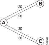
Configure Link Group Profile
Perform this task to configure Intermediate System-to-Intermediate System (IS-IS) link group profiles:
1.
configure
2.
router isis
instance-id
3.
link-group
link-group-name
{
[
metric-offset
count |
maximum
]
|
[
minimum-members
count
|
revert-members
count
]
}
4.
commit
5.
show isis
interface
6.
show isis
lsp
DETAILED STEPS
| Command or Action | Purpose | |||
|---|---|---|---|---|
| Step 1 |
configure
| |||
| Step 2 |
router isis
instance-id
Example:
RP/0/0/CPU0:router(config)# router isis purple
|
Enters IS-IS configuration submode. | ||
| Step 3 |
link-group
link-group-name
{
[
metric-offset
count |
maximum
]
|
[
minimum-members
count
|
revert-members
count
]
}
|
| ||
| Step 4 |
commit
| |||
| Step 5 |
show isis
interface
Example:
RP/0/0/CPU0:router# show isis interface
|
(Optional) If link-group is configured on the interface, when showing the IS-IS interface-related topology, this command displays the link-group and current offset-metric value. | ||
| Step 6 |
show isis
lsp
Example:
RP/0/0/CPU0:router# show isis lsp
|
(Optional) Displays the updated metric value. |
Configure Link Group Profile: Example
The following is an example configuration, along with the show isis interface output:
router isis 1
 is-type level-2-only
 net 49.1111.0000.0000.0006.00
 link-group foo
  metric-offset 100
  revert-members 4
  minimum-members 2
 !
 address-family ipv4 unicast
  metric-style wide
 !
 interface GigabitEthernet0/0/0/1
  point-to-point
  address-family ipv4 unicast
   link-group foo

RP/0/RSP0/CPU0:Iguazu#sh isis interface gig 0/0/0/1
Thu Jun 11 14:55:32.565 CEST

GigabitEthernet0/0/0/1      Enabled
  Adjacency Formation:      Enabled
  Prefix Advertisement:     Enabled
  IPv4 BFD:                 Disabled
  IPv6 BFD:                 Disabled
  BFD Min Interval:         150
  BFD Multiplier:           3

  Circuit Type:             level-2-only (Interface circuit type is level-1-2)
  Media Type:               P2P
  Circuit Number:           0
  Extended Circuit Number:  36
  Next P2P IIH in:          8 s
  LSP Rexmit Queue Size:    0

  Level-2
    Adjacency Count:        1
    LSP Pacing Interval:    33 ms
    PSNP Entry Queue Size:  0

  CLNS I/O
    Protocol State:         Up
    MTU:                    1497
    SNPA:                   0026.9829.af19
    Layer-2 MCast Groups Membership:
      All ISs:              Yes

  IPv4 Unicast Topology:    Enabled
    Adjacency Formation:    Running
    Prefix Advertisement:   Running
    Metric (L1/L2):         110/110
    Weight (L1/L2):         0/0
    MPLS Max Label Stack:   1
    MPLS LDP Sync (L1/L2):  Disabled/Disabled
    Link-Group (L1/L2):     Configured/Configured
      Metric-Offset (L1/L2):100/100

  IPv4 Address Family:      Enabled
    Protocol State:         Up
    Forwarding Address(es): 100.5.6.6
    Global Prefix(es):      100.5.6.0/24

  LSP transmit timer expires in 0 ms
  LSP transmission is idle
  Can send up to 9 back-to-back LSPs in the next 0 ms
Configure Link Group Interface
Note | One IS-IS interface and address-family can specify only one link-group association. The default is for both levels regardless of the current circuit-type. The link-group association can be specified for one level only if configured. |
1.
configure
2.
router isis
instance-id
3.
interface
type
interface-path-id
4.
address-family
ipv4 |
ipv6 [
unicast
]
5.
link-group
link-group-name
[
level
{1 |
2
} ]
6.
commit
7.
show isis
interface
DETAILED STEPS
| Command or Action | Purpose | |
|---|---|---|
| Step 1 |
configure
| |
| Step 2 |
router isis
instance-id
Example:
RP/0/0/CPU0:router(config)# router isis purple
|
Enters IS-IS configuration submode. |
| Step 3 |
interface
type
interface-path-id
Example:
RP/0/0/CPU0:router(config-isis)# interface GigabitEthernet 0/1/0/3
|
Enters interface configuration mode. |
| Step 4 |
address-family
ipv4 |
ipv6 [
unicast
]
Example:
RP/0/0/CPU0:router(config-isis)# address-family ipv4 unicast
|
Specifies the IPv6 address family and enters router address family configuration mode. |
| Step 5 |
link-group
link-group-name
[
level
{1 |
2
} ]
Example:
RP/0/0/CPU0:router(config-isis-if)# )#address-family ipv4 unicast link-group access level 1
|
Specifies the link-group name and sets the tag at the level specified. |
| Step 6 |
commit
| |
| Step 7 |
show isis
interface
Example:
RP/0/0/CPU0:router# show isis interface
|
(Optional) If link-group is configured on the interface, when showing the IS-IS interface-related topology, this command displays the link-group value. |
Configuration Examples for Implementing IS-IS
This section provides the following configuration examples:
- Configuring Single-Topology IS-IS for IPv6: Example
- Configuring Multitopology IS-IS for IPv6: Example
- Redistributing IS-IS Routes Between Multiple Instances: Example
- Tagging Routes: Example
- Configuring IS-IS Overload Bit Avoidance: Example
Configuring Single-Topology IS-IS for IPv6: Example
The following example shows single-topology mode being enabled. An IS-IS instance is created, the NET is defined, IPv6 is configured along with IPv4 on an interface, and IPv4 link topology is used for IPv6.
This configuration allows POS interface 0/3/0/0 to form adjacencies for both IPv4 and IPv6 addresses.
  router isis isp
   net 49.0000.0000.0001.00
   address-family ipv6 unicast
    single-topology
   interface POS0/3/0/0
    address-family ipv4 unicast
    !
    address-family ipv6 unicast
    !
    exit
  !
  interface POS0/3/0/0
   ipv4 address 10.0.1.3 255.255.255.0
   ipv6 address 2001::1/64
Configuring Multitopology IS-IS for IPv6: Example
The following example shows multitopology IS-IS being configured in IPv6.
  router isis isp
   net 49.0000.0000.0001.00
   interface POS0/3/0/0
    address-family ipv6 unicast
    metric-style wide level 1
    exit
  !
  interface POS0/3/0/0
   ipv6 address 2001::1/64
Redistributing IS-IS Routes Between Multiple Instances: Example
The following example shows usage of the attached-bit send always-set and redistribute commands. Two instances, instance “1” restricted to Level 1 and instance “2” restricted to Level 2, are configured.
The Level 1 instance is propagating routes to the Level 2 instance using redistribution. Note that the administrative distance is explicitly configured higher on the Level 2 instance to ensure that Level 1 routes are preferred.
Attached bit is being set for the Level 1 instance since it is redistributing routes into the Level 2 instance. Therefore, instance “1” is a suitable candidate to get from the area to the backbone.
  router isis 1
    is-type level-2-only
   net 49.0001.0001.0001.0001.00
   address-family ipv4 unicast
    distance 116
    redistribute isis 2 level 2
  !
  interface GigabitEthernet 0/3/0/0
   address-family ipv4 unicast
  !
  !
  router isis 2
   is-type level-1
   net 49.0002.0001.0001.0002.00
   address-family ipv4 unicast

attached-
bit send always-
set
  !
  interface GigabitEthernet 0/1/0/0
   address-family ipv4 unicast
Tagging Routes: Example
The following example shows how to tag routes.
  route-policy isis-tag-55
  end-policy
  !
  route-policy isis-tag-555
    if destination in (5.5.5.0/24 eq 24) then
      set tag 555
      pass
    else
      drop
    endif
  end-policy
  !
  router static
   address-family ipv4 unicast
    0.0.0.0/0 2.6.0.1
    5.5.5.0/24 Null0
   !
  !
  router isis uut
   net 00.0000.0000.12a5.00
   address-family ipv4 unicast
    metric-style wide
    redistribute static level-1 route-policy isis-tag-555
    spf prefix-priority critical tag 13
    spf prefix-priority high tag 444
    spf prefix-priority medium tag 777
Configuring IS-IS Overload Bit Avoidance: Example
The following example shows how to activate IS-IS overload bit avoidance:
  config
   mpls traffic-eng path-selection ignore overload
The following example shows how to deactivate IS-IS overload bit avoidance:
  config
   no mpls traffic-eng path-selection ignore overload
Where to Go Next
To implement more IP routing protocols, see the following document modules in Cisco IOS XR Routing Configuration Guide for the Cisco XR 12000 Series Router:
Additional References
The following sections provide references related to implementing IS-IS.
Related Documents
|
Related Topic |
Document Title |
|---|---|
|
IS-IS commands: complete command syntax, command modes, command history, defaults, usage guidelines, and examples |
Cisco IOS XR Routing Command Reference for the Cisco XR 12000 Series Router |
|
MPLS TE feature information |
Implementing MPLS Traffic Engineering on Cisco IOS XR Software module in Cisco IOS XR MPLS Configuration Guide for the Cisco XR 12000 Series Router |
|
IS-IS TLVs |
Intermediate System-to-Intermediate System (IS-IS) TLVs at: http://www.cisco.com/en/US/tech/tk365/technologies_tech_note09186a0080094bbd.shtml |
|
Bidirectional Forwarding Detection (BFD) |
Cisco IOS XR Interface and Hardware Component Configuration Guide for the Cisco XR 12000 Series Router and Cisco IOS XR Interface and Hardware Component Command Reference for the Cisco XR 12000 Series Router |
Standards
|
Standards |
Title |
|---|---|
|
Draft-ietf-isis-ipv6-05.txt |
Routing IPv6 with IS-IS, by Christian E. Hopps |
|
Draft-ietf-isis-wg-multi-topology-06.txt |
M-ISIS: Multi Topology (MT) Routing in IS-IS, by Tony Przygienda, Naiming Shen, and Nischal Sheth |
|
Draft-ietf-isis-traffic-05.txt |
IS-IS Extensions for Traffic Engineering, by Henk Smit and Toni Li |
|
Draft-ietf-isis-restart-04.txt |
Restart Signaling for IS-IS, by M. Shand and Les Ginsberg |
|
Draft-ietf-isis-igp-p2p-over-lan-05.txt |
Point-to-point operation over LAN in link-state routing protocols, by Naiming Shen |
|
Draft-ietf-rtgwg-ipfrr-framework-06.txt |
IP Fast Reroute Framework, by M. Shand and S. Bryant |
|
Draft-ietf-rtgwg-lf-conv-frmwk-00.txt |
A Framework for Loop-free Convergence, by M. Shand and S. Bryant |
MIBs
|
MIBs |
MIBs Link |
|---|---|
| — |
To locate and download MIBs using Cisco IOS XR software, use the Cisco MIB Locator found at the following URL and choose a platform under the Cisco Access Products menu: http://cisco.com/public/sw-center/netmgmt/cmtk/mibs.shtml |
RFCs
|
RFCs |
Title |
|---|---|
|
RFC 1142 |
OSI IS-IS Intra-domain Routing Protocol |
|
RFC 1195 |
Use of OSI IS-IS for Routing in TCP/IP and Dual Environments |
|
RFC 2763 |
Dynamic Hostname Exchange Mechanism for IS-IS |
|
RFC 2966 |
Domain-wide Prefix Distribution with Two-Level IS-IS |
|
RFC 2973 |
IS-IS Mesh Groups |
|
RFC 3277 |
IS-IS Transient Blackhole Avoidance |
|
RFC 3373 |
Three-Way Handshake for IS-IS Point-to-Point Adjacencies |
|
RFC 3567 |
IS-IS Cryptographic Authentication |
|
RFC 4444 |
IS-IS Management Information Base |
Technical Assistance
|
Description |
Link |
|---|---|
|
The Cisco Technical Support website contains thousands of pages of searchable technical content, including links to products, technologies, solutions, technical tips, and tools. Registered Cisco.com users can log in from this page to access even more content. |
 Feedback